U.S. Pat. No. 12,005,345
VIDEO GAME CONTROLLER
Issue DateOctober 18, 2021
Joysticks have been synonymous with video games since video games achieved commercial success in the 1970s. In the years since then, there have been some fascinating takes on what a joystick can be, and a handful of these attempts are traceable in the patent record. In this post, let’s have a look at some of the most memorable joystick patents over the years.
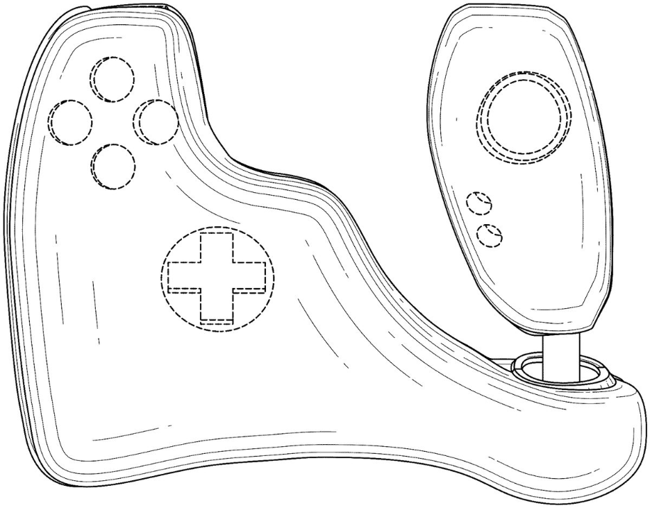
U.S. Design Pat. No. D1,065,338 concerns this “ornamental design for a joystick game controller.” It would appear that the buttons and directional pad on the left of the diagram are contoured to fit one’s hand. The patent was issued in 2023, so it’s still possible that we might see this design on the commercial market someday.
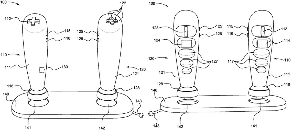
Issued in 2021, U.S. Pat. No. 12,005,345 relates to a controller that features a pair of joysticks. The buttons and directional pad sit on top of their respective joysticks. There are also “a plurality of action buttons” included on the front of each joystick. The design looks like a deconstructed version of the typical controller one might see bundled with a console these days.
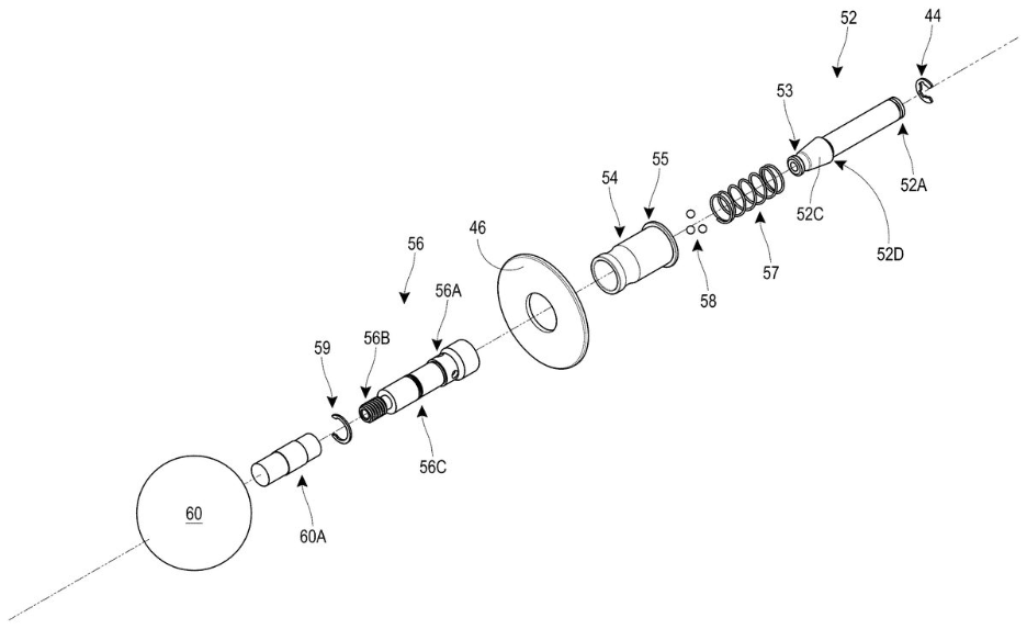
U.S. Pat. No. 10,272,327 from 2017 demonstrates how some companies are interested in patenting specific parts of their controller designs. This proprietary joystick is meant “for use with a video game controller,” but the language in the patent pays particular attention to the ability of the component to be taken apart efficiently: “This assembly facilitates travel with the video game controller by allowing decoupling of the joystick while preventing misplacement or loss of the dust cover.”
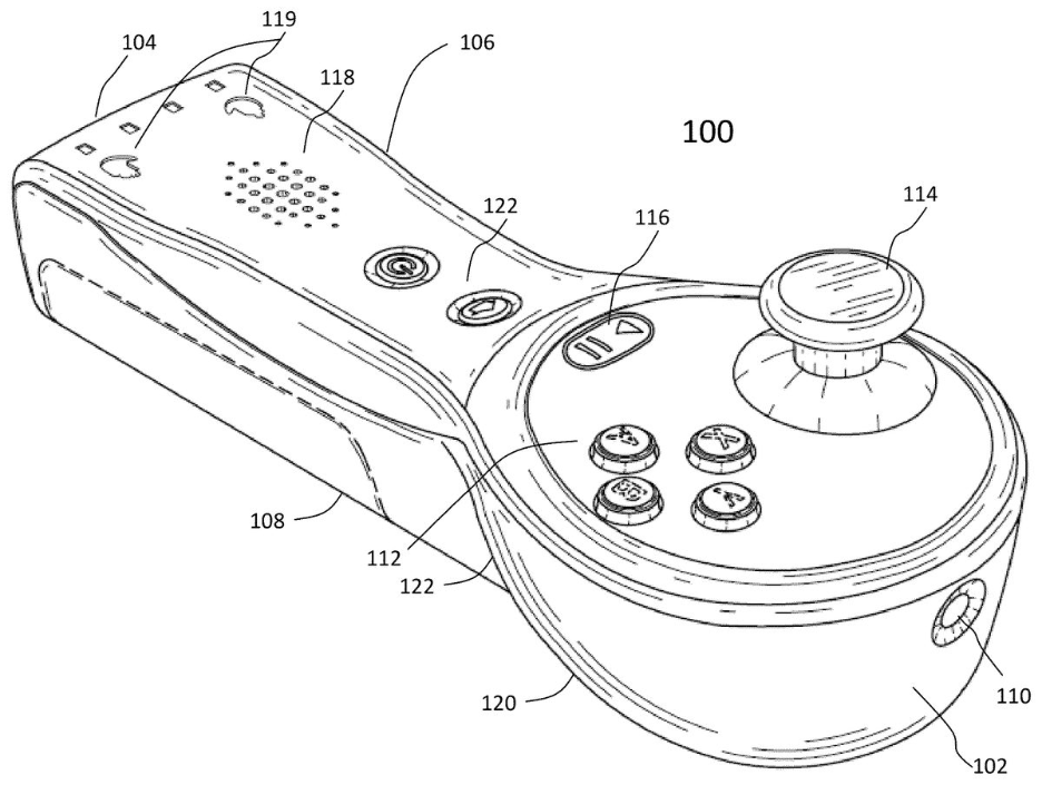
Last but not least, U.S. Pat. No. 8,795,077 was issued in the midst of Nintendo Wii mania. You can clearly see the influence of the Wii controller on this design. However, this one–which the U.S. Patent Office issued to AiLive Inc. on October 24, 2010–features a joystick on its face, making it a more all-in-one design than the Wii Remote, which featured a socket for a proprietary Nintendo Nunchuk attachment.
Illustrative Figure

Abstract
A video game controller, including a first joystick, including a first body having an elongate shape, and a directional pad disposed on at least a portion of a first end of the first body to input at least one input corresponding to each point of the directional pad, a second joystick, including a second body having an elongate shape, and a plurality of action buttons disposed on at least a portion of the second body to input at least one action input in response to depressing at least one of the plurality of action buttons, and a base to removably connect to at least one of a second end of the first body and a second end of the second body.
Description
DETAILED DESCRIPTION Various example embodiments (a.k.a., exemplary embodiments) will now be described more fully with reference to the accompanying drawings in which some example embodiments are illustrated. In the figures, the thicknesses of lines, layers and/or regions may be exaggerated for clarity. Accordingly, while example embodiments are capable of various modifications and alternative forms, embodiments thereof are shown by way of example in the figures and will herein be described in detail. It should be understood, however, that there is no intent to limit example embodiments to the particular forms disclosed, but on the contrary, example embodiments are to cover all modifications, equivalents, and alternatives falling within the scope of the disclosure. Like numbers refer to like/similar elements throughout the detailed description. It is understood that when an element is referred to as being “connected” or “coupled” to another element, it can be directly connected or coupled to the other element or intervening elements may be present. In contrast, when an element is referred to as being “directly connected” or “directly coupled” to another element, there are no intervening elements present. Other words used to describe the relationship between elements should be interpreted in a like fashion (e.g., “between” versus “directly between,” “adjacent” versus “directly adjacent,” etc.). The terminology used herein is for the purpose of describing particular embodiments only and is not intended to be limiting of example embodiments. As used herein, the singular forms “a,” “an” and “the” are intended to include the plural forms as well, unless the context clearly indicates otherwise. It will be further understood that the terms “comprises,” “comprising,” “includes” and/or “including,” when used herein, specify the presence of stated features, integers, steps, operations, elements and/or components, but do not preclude the presence or addition of one or more other features, integers, steps, operations, ...
DETAILED DESCRIPTION
Various example embodiments (a.k.a., exemplary embodiments) will now be described more fully with reference to the accompanying drawings in which some example embodiments are illustrated. In the figures, the thicknesses of lines, layers and/or regions may be exaggerated for clarity.
Accordingly, while example embodiments are capable of various modifications and alternative forms, embodiments thereof are shown by way of example in the figures and will herein be described in detail. It should be understood, however, that there is no intent to limit example embodiments to the particular forms disclosed, but on the contrary, example embodiments are to cover all modifications, equivalents, and alternatives falling within the scope of the disclosure. Like numbers refer to like/similar elements throughout the detailed description.
It is understood that when an element is referred to as being “connected” or “coupled” to another element, it can be directly connected or coupled to the other element or intervening elements may be present. In contrast, when an element is referred to as being “directly connected” or “directly coupled” to another element, there are no intervening elements present. Other words used to describe the relationship between elements should be interpreted in a like fashion (e.g., “between” versus “directly between,” “adjacent” versus “directly adjacent,” etc.).
The terminology used herein is for the purpose of describing particular embodiments only and is not intended to be limiting of example embodiments. As used herein, the singular forms “a,” “an” and “the” are intended to include the plural forms as well, unless the context clearly indicates otherwise. It will be further understood that the terms “comprises,” “comprising,” “includes” and/or “including,” when used herein, specify the presence of stated features, integers, steps, operations, elements and/or components, but do not preclude the presence or addition of one or more other features, integers, steps, operations, elements, components and/or groups thereof.
Unless otherwise defined, all terms (including technical and scientific terms) used herein have the same meaning as commonly understood by one of ordinary skill in the art to which example embodiments belong. It will be further understood that terms, e.g., those defined in commonly used dictionaries, should be interpreted as having a meaning that is consistent with their meaning in the context of the relevant art. However, should the present disclosure give a specific meaning to a term deviating from a meaning commonly understood by one of ordinary skill, this meaning is to be taken into account in the specific context this definition is given herein.
LIST OF COMPONENTS
Video Game Controller100First Joystick110First Body111Directional Pad112First Trigger Button113First Bumper Button114First Menu Button115First Home Button116Finger Receiving Grooves117First Pivoting Portion118First Connector119Second Joystick120Second Body121Action Buttons122Second Trigger Button123Second Bumper Button124Second Menu Button125Second Home Button126Finger Receiving Grooves127Second Pivoting Portion128Second Connector129Heart Rate Sensor130Base140First Joystick Receiving Groove141Second Joystick Receiving Groove142Power Source143
FIG.1Aillustrates a rear perspective view of a video game controller100, according to an exemplary embodiment of the present general inventive concept.
FIG.1Billustrates a front perspective view of the video game controller100, according to an exemplary embodiment of the present general inventive concept.
FIG.2illustrates a zoomed in view of a bottom portion of the video game controller100, according to an exemplary embodiment of the present general inventive concept.
The video game controller100may be constructed from at least one of metal, plastic, wood, glass, and rubber, etc., but is not limited thereto.
The video game controller100may include a first joystick110, a second joystick120, a heart rate sensor130, and a base140, but is not limited thereto.
The first joystick110may include a first body111, a directional pad112, a first trigger button113, a first bumper button114, a first menu button115, a first home button116, a plurality of finger receiving grooves117, a first pivoting portion118, and a first connector119, but is not limited thereto.
Referring toFIG.1, the first body111may have an elongate shape. Moreover, the first body111may have a variety of sizes based on a size of a hand of a user. In other words, a size of the first body111for an adult may be greater than a size of the first body111for a child. The first body111may receive a first hand thereon.
The directional pad112may be disposed on at least a portion of a first end (i.e. top end) of the first body111. The directional pad112may have a cross shape, such that the directional pad112may provide at least one input (e.g., four different inputs) corresponding to each point of the cross. For example, the directional pad112may input north, south, east, and/or west based on a section of the directional pad112being depressed.
The first trigger button113may be disposed on at least a portion of a first side of the first body111. The first trigger button113may input a first trigger command in response to being depressed. For example, the first trigger button113may fire a weapon in a video game in response to being depressed.
The first bumper button114may be disposed on at least a portion of the first side of the first body111below the first trigger button113(i.e. towards a second end of the first body111). The first bumper button114may input a first bumper command in response to being depressed. For example, the first bumper button114may reload the weapon in the video game in response to being depressed.
The first menu button115may be disposed on at least a portion of a second side of the first body111different from the first side. The first menu button115may input a menu command in response to being depressed. For example, the first menu button115may open a game menu in the video game in response to being depressed.
The first home button116may be disposed on at least a portion of the second side of the first body111below the first menu button115(i.e. towards the second end of the first body111). The first home button116may input a home menu command in response to being depressed. For example, the first home button116may navigate to a home screen of a game system in response to being depressed.
The plurality of finger receiving grooves117may be concavely disposed on at least a portion of the first side of the first body111below the first bumper button114. Moreover, the plurality of finger receiving grooves117may facilitate gripping thereof. Specifically, the plurality of finger receiving grooves117may curve toward an interior portion of the first body111to receive at least one finger therein, such that the plurality of finger receiving grooves117may prevent movement of the at least one finger in a perpendicular direction with respect to each of the plurality of finger receiving grooves117.
The first pivoting portion118may be disposed on at least a portion of the second end of the first body111. The first pivoting portion118may facilitate movement of the first body111. Moreover, the first body111may move (i.e. pivot) in response to an application of force thereto against the first pivoting portion118in any direction (i.e. three hundred sixty degrees) with respect to a first plane that is perpendicular with respect to a length of the first body111from the first end to the second end thereof. Also, the first body111may pivot a predetermined angle with respect to a second plane parallel to the length of the first body111from the first end to the second end. For example, the first body111may pivot thirty degrees forward, backward, left, and/or right.
The first connector119may be springingly (i.e., using a spring) disposed on at least a portion of the second end of the first body111. The first connector119may be contact pins and include a battery therein.
The second joystick120may include a second body121, a plurality of action buttons122, a second trigger button123, a second bumper button124, a second menu button125, a second home button126, a plurality of finger receiving grooves127, a second pivoting portion128, and a second connector129, but is not limited thereto.
Referring toFIG.1, the second body121may have an elongate shape. Moreover, the second body121may have a variety of sizes based on the size of the hand of the user. In other words, a size of the second body121for an adult may be greater than a size of the second body121for a child. The second body121may receive a second hand thereon.
The plurality of action buttons122may be disposed on at least a portion of a first end (i.e. top end) of the second body121. The plurality of action buttons122may have a cross shape, such that the plurality of action buttons122may provide four different inputs corresponding to each of the plurality of action buttons122. For example, a first of the plurality of action buttons122may input “A”, a second of the plurality of action buttons122may input “B”, a third of the plurality of action buttons122may input “X”, “and a fourth of the plurality of action buttons122may input “Y” in response to being depressed. In other words, the plurality of action buttons122may input at least one action input in response to depressing at least one of the plurality of action buttons122. Accordingly, the plurality of action buttons122may perform different actions based on the video game.
The second trigger button123may be disposed on at least a portion of a first side of the second body121. The second trigger button123may input a second trigger command in response to being depressed. For example, the second trigger button123may fire a weapon in the video game in response to being depressed.
The second bumper button124may be disposed on at least a portion of the first side of the second body121below the second trigger button123(i.e. towards a second end of the second body121). The second bumper button124may input a second bumper command in response to being depressed. For example, the second bumper button124may reload the weapon in the video game in response to being depressed.
The second menu button125may be disposed on at least a portion of a second side of the second body121different from the first side. The second menu button125may input a menu command in response to being depressed. For example, the second menu button125may open a game menu in the video game in response to being depressed.
The second home button126may be disposed on at least a portion of the second side of the second body121below the second menu button125(i.e. towards the second end of the second body121). The second home button126may input a home menu command in response to being depressed. For example, the second home button126may navigate to a home screen of a game system in response to being depressed.
The plurality of finger receiving grooves127may be concavely disposed on at least a portion of the first side of the second body121below the second bumper button124. Moreover, the plurality of finger receiving grooves127may facilitate gripping thereof. Specifically, the plurality of finger receiving grooves127may curve toward an interior portion of the first body121to receive at least one finger therein, such that the plurality of finger receiving grooves127may prevent movement of the at least one finger in a perpendicular direction with respect to each of the plurality of finger receiving grooves127.
The second pivoting portion128may be disposed on at least a portion of the second end of the second body121. The second pivoting portion128may facilitate movement of the second body121. Moreover, the second body121may move (i.e. pivot) in response to an application of force thereto against the second pivoting portion128in any direction (i.e. three hundred sixty degrees) with respect to a first plane that is perpendicular with respect to a length of the second body121from the first end to the second end thereof. Also, the second body121may pivot a predetermined angle with respect to a second plane parallel to the length of the second body121from the first end to the second end. For example, the second body121may pivot thirty degrees forward, backward, left, and/or right.
The second connector129may be springingly (i.e., using a spring) disposed on at least a portion of the second end of the second body121. The second connector129may be contact pins and include a battery therein.
The heart rate sensor130may be disposed within at least a portion of the first body111and/or the second body121. The heart rate sensor130may detect a heart rate level in response to contact from the hand of the user. Additionally, for example, the heart rate sensor130may affect the video game in response to the heart rate level exceeding a predetermined heart rate level.
The base140may include a first joystick receiving groove141, a second joystick receiving groove142, and a power source143, but is not limited thereto.
The first joystick receiving groove141may receive the first joystick110therein. Specifically, the first connector119may removably connect to the first joystick receiving groove141.
The second joystick receiving groove142may receive the second joystick120therein. Specifically, the second connector129may removably connect to the second joystick receiving groove142. As such, the base140may stabilize the first joystick110and/or the second joystick120while connected to the base140.
The power source143may include a power inlet, a battery, and a solar cell, but is not limited thereto.
The power source143may be disposed on and/or within at least a portion of the base140. The power source143may send power to the first joystick110through the first joystick receiving groove141in response to connecting the first connector119to the first joystick receiving groove141. Similarly, the power source143may send power to the second joystick120through the second joystick receiving groove142in response to connecting the second connector129to the second joystick receiving groove142. In other words, the base140may charge the first joystick110and/or the second joystick120.
Optionally, the first body111and/or the second body121may be moved toward the base140in response to an application of force thereto, such that the first body111and/or the second body121may generate another at least one input, such as enter and/or accept based on the video game. Also, the first body111and/or the second body121may automatically return to an original position after removing the application of force due to a spring bias.
Therefore, the video game controller100may provide joystick and/or analog movement capabilities through movement of the first body111and/or the second body121while also providing buttons for depressing without having to move the thumbs.
The present general inventive concept may include a video game controller100, including a first joystick110, including a first body111having an elongate shape, and a directional pad112disposed on at least a portion of a first end of the first body111to input at least one input corresponding to each point of the directional pad112, a second joystick120, including a second body121having an elongate shape, and a plurality of action buttons122disposed on at least a portion of the second body121to input at least one action input in response to depressing at least one of the plurality of action buttons122, and a base140to removably connect to at least one of a second end of the first body111and a second end of the second body121.
The first joystick110may further include a first trigger button113disposed on at least a portion of a first side of the first body111to input a first trigger command in response to being depressed, a first bumper button114disposed on at least a portion of the first side of the first body111to input a first bumper command in response to being depressed, a first menu button115disposed on at least a portion of a second side of the first body111different from the first side to input a menu command in response to being depressed, and a first home button116disposed on at least a portion of the second side of the first body111to input a home menu command in response to being depressed.
The first joystick110may further include a plurality of finger receiving grooves117concavely disposed on at least a portion of the first side of the first body111to facilitate gripping thereof.
The second joystick120may further include a second trigger button123disposed on at least a portion of a first side of the second body121to input a second trigger command in response to being depressed, a second bumper button124disposed on at least a portion of the first side of the second body121to input a second bumper command in response to being depressed, a second menu button125disposed on at least a portion of a second side of the second body121different from the first side to input a menu command in response to being depressed, and a second home button126disposed on at least a portion of the second side of the second body121to input a home menu command in response to being depressed.
The second joystick120may further include a plurality of finger receiving grooves127concavely disposed on at least a portion of a first side of the second body121to facilitate gripping thereof.
The first joystick110and the second joystick120, each may further include a pivoting portion disposed on the second end to facilitate movement in any direction with respect to a first plane.
The first joystick110and the second joystick120, each may further include a connector disposed on at least a portion of the second end to receive power from the base.
The video game controller100may further include a heart rate sensor130disposed within at least a portion of at least one of the first body111and the second body121to detect a heart rate level in response to contact from a hand of the user.
Although a few embodiments of the present general inventive concept have been shown and described, it will be appreciated by those skilled in the art that changes may be made in these embodiments without departing from the principles and spirit of the general inventive concept, the scope of which is defined in the appended claims and their equivalents.
Claims
- A video game controller, comprising: a first joystick, comprising: a first body having an elongate shape, and a directional pad disposed on at least a portion of a first end of the first body to input at least one input corresponding to each point of the directional pad;a second joystick, comprising: a second body having an elongate shape, and a plurality of action buttons disposed on at least a portion of the second body to input at least one action input in response to depressing at least one of the plurality of action buttons;and a base to removably connect to at least one of a second end of the first body and a second end of the second body, such that a bottom-most surface of the second end of the first body is flat to attach to a flat portion of the base, and a bottom-most surface of the second end of the second body is flat to attach to another flat portion of the base, wherein the first joystick further comprises a first pivoting portion disposed at the second end above a bottom-most surface of the second end of the first body, to facilitate movement of the first joystick in any direction with respect to a first plane, and wherein the second joystick further comprises a second pivoting portion disposed at the second end above a bottom-most surface of the second end of the second body, to facilitate movement of the second joystick in any direction with respect to a first plane.
- The video game controller of claim 1, wherein the first joystick further comprises: a first trigger button disposed on at least a portion of a first side of the first body to input a first trigger command in response to being depressed;a first bumper button disposed on at least a portion of the first side of the first body to input a first bumper command in response to being depressed;a first menu button disposed on at least a portion of a second side of the first body different from the first side to input a menu command in response to being depressed;and a first home button disposed on at least a portion of the second side of the first body to input a home menu command in response to being depressed.
- The video game controller of claim 1, wherein the first joystick further comprises: a plurality of finger receiving grooves concavely disposed on at least a portion of the first side of the first body to facilitate gripping thereof.
- The video game controller of claim 1, wherein the second joystick further comprises: a second trigger button disposed on at least a portion of a first side of the second body to input a second trigger command in response to being depressed;a second bumper button disposed on at least a portion of the first side of the second body to input a second bumper command in response to being depressed;a second menu button disposed on at least a portion of a second side of the second body different from the first side to input a menu command in response to being depressed;and a second home button disposed on at least a portion of the second side of the second body to input a home menu command in response to being depressed.
- The video game controller of claim 1, wherein the second joystick further comprises: a plurality of finger receiving grooves concavely disposed on at least a portion of a first side of the second body to facilitate gripping thereof.
- The video game controller of claim 1, wherein the first joystick and the second joystick, each further comprise: a connector disposed on at least a portion of the second end to receive power from the base.
- The video game controller of claim 1, further comprising: a heart rate sensor disposed within at least a portion of at least one of the first body and the second body to detect a heart rate level in response to contact from a hand of the user.
Disclaimer: Data collected from the USPTO and may be malformed, incomplete, and/or otherwise inaccurate.