U.S. Pat. No. 10,272,327
DETACHABLE JOYSTICK FOR VIDEO GAME CONTROLLER
AssigneePerformance Designed Products LLC
Issue DateAugust 31, 2017
Joysticks have been synonymous with video games since video games achieved commercial success in the 1970s. In the years since then, there have been some fascinating takes on what a joystick can be, and a handful of these attempts are traceable in the patent record. In this post, let’s have a look at some of the most memorable joystick patents over the years.
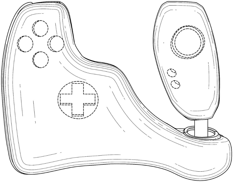
U.S. Design Pat. No. D1,065,338 concerns this “ornamental design for a joystick game controller.” It would appear that the buttons and directional pad on the left of the diagram are contoured to fit one’s hand. The patent was issued in 2023, so it’s still possible that we might see this design on the commercial market someday.
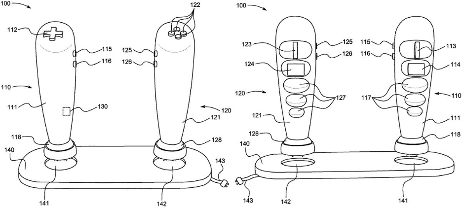
Issued in 2021, U.S. Pat. No. 12,005,345 relates to a controller that features a pair of joysticks. The buttons and directional pad sit on top of their respective joysticks. There are also “a plurality of action buttons” included on the front of each joystick. The design looks like a deconstructed version of the typical controller one might see bundled with a console these days.

U.S. Pat. No. 10,272,327 from 2017 demonstrates how some companies are interested in patenting specific parts of their controller designs. This proprietary joystick is meant “for use with a video game controller,” but the language in the patent pays particular attention to the ability of the component to be taken apart efficiently: “This assembly facilitates travel with the video game controller by allowing decoupling of the joystick while preventing misplacement or loss of the dust cover.”
Last but not least, U.S. Pat. No. 8,795,077 was issued in the midst of Nintendo Wii mania. You can clearly see the influence of the Wii controller on this design. However, this one–which the U.S. Patent Office issued to AiLive Inc. on October 24, 2010–features a joystick on its face, making it a more all-in-one design than the Wii Remote, which featured a socket for a proprietary Nintendo Nunchuk attachment.
Illustrative Figure
Abstract
A removable joystick for use with a video game controller includes a base shaft that is coupled to a joystick unit in the housing of the video game controller so that the proximal end of the base shaft extends to a location at or below an outer surface of the housing. A top shaft assembly is removably coupleable to the base shaft. The top shaft assembly includes a top shaft with a proximal end that removably couples to a joystick ball. The top shaft assembly also includes a collar that is spring loaded and movably coupled to the top shaft and has a flange that extends outward from the outer surface of the collar. The top shaft assembly removably couples to the base shaft via a quick disconnect assembly. When the top shaft assembly is disconnected from the base shaft, the flange of the collar engages and retains a dust cover disposed over the collar to inhibit misplacement or loss of the dust cover. This assembly facilitates travel with the video game controller by allowing decoupling of the joystick while preventing misplacement or loss of the dust cover.
Description
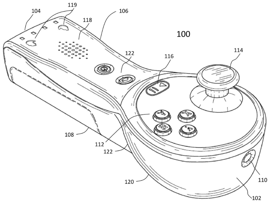
DETAILED DESCRIPTION FIGS. 1-3show a video game controller100(the “controller100”) that can be removably coupled to a video game unit (e.g., video game console), via a connector35(e.g., which can optionally couple to a cable that couples to a video game console). The video game controller100can be used with fight video games or arcade style video games. The controller100has a housing10with a top surface12that has a portion12aon which the user can optionally rests their wrists while operating the controller100. The controller100can also have a rear surface20and optionally have one or more handles22defined (e.g., by openings) in the rear surface20with which the user can grab the housing10. The rear surface20can also optionally have a removable bottom cover24to access the electronics in the housing10. Optionally, the bottom cover24is pivotally coupled to the housing10of the controller100with one or more hinges25(seeFIG. 11A) that allow the bottom cover24to be moved between an open position and a closed position relative to the housing10. A latch26(seeFIG. 11A) can be actuated to lock and unlock the cover24relative to the housing10. The controller100can optionally have one or more buttons30on the top surface12for actuating one or more functions of the video game during operation. The controller100can also have a joystick unit40that includes a joystick assembly50. The user can pivot the joystick assembly50to actuate a function of the video game during operation. A dust cover46is disposed about the joystick assembly50and adjacent the top surface12of the housing10. The dust cover12covers an opening14in the housing10within which the joystick assembly50pivots to inhibit ingress of dust and foreign material into the housing10via the opening14. FIGS. 3-5show the joystick unit40in greater detail. The joystick unit40includes an actuator42that is disposed in the housing10. The actuator42has a mounting plate42athat can be coupled to the housing so that the mounting plate42afaces an underside of the top surface12(e.g., the mounting plate42ais fastened ...
DETAILED DESCRIPTION
FIGS. 1-3show a video game controller100(the “controller100”) that can be removably coupled to a video game unit (e.g., video game console), via a connector35(e.g., which can optionally couple to a cable that couples to a video game console). The video game controller100can be used with fight video games or arcade style video games. The controller100has a housing10with a top surface12that has a portion12aon which the user can optionally rests their wrists while operating the controller100. The controller100can also have a rear surface20and optionally have one or more handles22defined (e.g., by openings) in the rear surface20with which the user can grab the housing10. The rear surface20can also optionally have a removable bottom cover24to access the electronics in the housing10. Optionally, the bottom cover24is pivotally coupled to the housing10of the controller100with one or more hinges25(seeFIG. 11A) that allow the bottom cover24to be moved between an open position and a closed position relative to the housing10. A latch26(seeFIG. 11A) can be actuated to lock and unlock the cover24relative to the housing10.
The controller100can optionally have one or more buttons30on the top surface12for actuating one or more functions of the video game during operation. The controller100can also have a joystick unit40that includes a joystick assembly50. The user can pivot the joystick assembly50to actuate a function of the video game during operation. A dust cover46is disposed about the joystick assembly50and adjacent the top surface12of the housing10. The dust cover12covers an opening14in the housing10within which the joystick assembly50pivots to inhibit ingress of dust and foreign material into the housing10via the opening14.
FIGS. 3-5show the joystick unit40in greater detail. The joystick unit40includes an actuator42that is disposed in the housing10. The actuator42has a mounting plate42athat can be coupled to the housing so that the mounting plate42afaces an underside of the top surface12(e.g., the mounting plate42ais fastened to an underside of the top surface12). The joystick unit40also includes a joystick assembly50that couples to the actuator42. The joystick assembly50is also illustrated inFIGS. 6-8
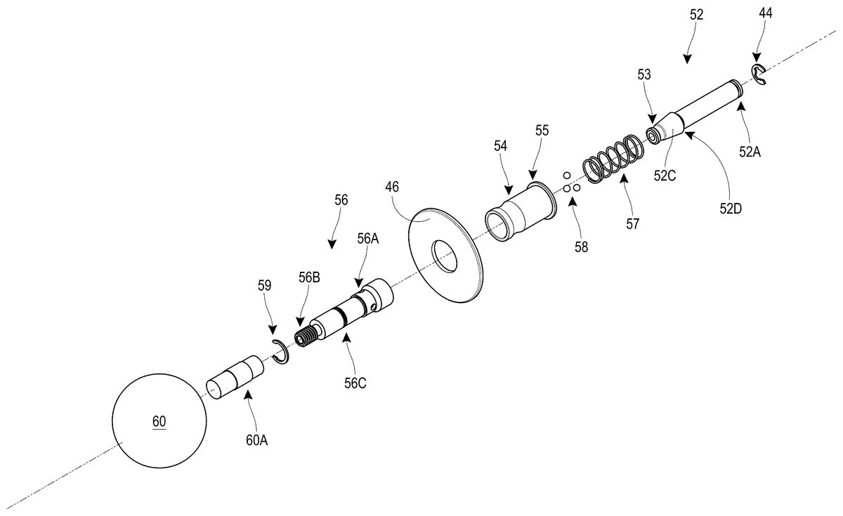
The joystick assembly50includes a base shaft52that can be coupled to the actuator42with a clip44(e.g., e-clip) that extends in a slot52A at a distal end of the base shaft52. The base shaft52can have a bore52B that extends along its length, and can also have a circumferential recess53near a proximal end of the base shaft52. The base shaft52can have a conical surface52C adjacent the circumferential recess53that extends to a shoulder52D.
The joystick assembly50also includes a collar54with a flange55, where the collar54is movably mounted onto a top shaft56to define a quick release or quick disconnect fitting (e.g., a ball-lock quick disconnect). The flange55can optionally extend radially outward from the collar54by a distance of between about 0.5 mm and about 3 mm, such as about 1 mm or about 1.2 mm. The collar54can have a shoulder54A that extends radially inward from an inner surface of the collar54, a proximal cylindrical section54B with a first inner diameter D1, an intermediate cylindrical section54C with a second inner diameter D2, and a distal cylindrical section54C with a third inner diameter D3. Diameter D1and Diameter D3are greater than diameter D2, and diameter D3is optionally greater than diameter D1.
A spring57can be disposed over at least a portion of the top shaft56and between the top shaft56and the collar54and allows the collar54to be spring loaded relatively to the top shaft56. As best shown inFIG. 7, the spring57is disposed between a clip (e.g., e-clip)59disposed in a recess56C of the top shaft56and the shoulder54A of the collar54. The collar54can move from a distal biased position to a proximal position to allow the top shaft56to decouple from the base shaft52. The top shaft56can have a central bore56D with one or more openings56A that movably retain metal balls58therein, allowing them to move radially by a certain amount that allows the top shaft56to couple to and decouple from the base shaft52, as further described below. The top shaft56can also have a threaded portion56B that removably threads on to a ball60(e.g., threads into a threaded portion60A of the ball60).
In use, when the collar54is in the biased position and the top shaft56is disposed over at least a portion of the base shaft52, the balls58slide into the circumferential recess53of the base shaft52to intercouple the top shaft56to the base shaft52. When the collar54is slid toward the proximal position (acting against the spring force), the intermediate cylindrical section54C slides out of contact with the surface of the top shaft56, allowing the balls58to move at least partially into the openings56A in the top shaft56and out of the circumferential recess53of the base shaft52as the top shaft56is pulled away from the base shaft52. Therefore, the top shaft56, with the ball60attached thereto, and the collar54can be decoupled from the base shaft52to facilitate travel of the controller100. Optionally, when the collar54and top shaft56are decoupled from the base shaft52, the base shaft52does not protrude from the opening14of the housing10(e.g., the base shaft52extends to a proximal end that is at or below a plane of the top surface12), thereby making it easy for the controller100to fit into a back pack, travel bag or suitcase and inhibit damage to the controller100or joystick during travel.
Advantageously, as the collar54and top shaft56are decoupled from the base shaft52, the flange55of the collar54engages a surface of the dust cover46so that the dust cover46is retained on the collar54. This advantageously inhibits (e.g., prevents) the misplacement or loss of the dust cover46while the top shaft56and collar54are decoupled from the base shaft52, such as during storage or travel of the controller100.
FIG. 9A-9Cillustrate another joystick assembly50′ for use with the controller100and that can be decoupled from the controller100(e.g., during storage or travel of the controller100). The joystick assembly50′ is constructed similar to the joystick assembly50shown inFIGS. 6-8, except as noted below. Thus the reference numerals used to designate the various components of the joystick assembly50′ are identical to those used for identifying the corresponding components of the joystick assembly50inFIGS. 6-8, except that a “′” has been added to the reference numerals.
The joystick assembly50′ includes a top shaft56′ and a collar or sleeve54′ that is movably mounted (e.g., slidably mounted) over the top shaft56′. The collar or sleeve54′ is optionally spring loaded relative to the top shaft56′ in the same manner described above for the joystick assembly50. The collar or sleeve54′ is optionally cylindrical with a constant outer diameter D along the length of the sleeve54′.
The top shaft56′ has a proximal end56B′ that extends within and couples to the head60′ such that an annular gap G is defined between an inner circumferential surface60B′ of the head60′ and an outer surface56D′ of a proximal portion of the top shaft56′. The head60′ can be elongated (e.g., bat shaped) with a wider proximal portion that tapers toward a relatively narrower distal portion. The top shaft56′ also has a distal end56E′ that removably receives a proximal portion of the base shaft52. The sleeve54′ can have a flange55′ at its distal end. The flange55′ can have the same dimensions as the flange55, and can retain the dust cover46when the joystick assembly50′ is decoupled from the controller100′. The sleeve54′ defines a quick release or quick disconnect fitting (e.g., a ball-lock quick disconnect) that removably couples to the distal end of the top shaft56′ to the base shaft52. The quick release or quick disconnect structure can be identical to that described above for the joystick assembly50.
The proximal end of the sleeve54′ can extend further into the annular gap G when the sleeve54′ is moved in a proximal direction relative to the top shaft56′ (e.g., to decouple the top shaft56′ from the base shaft52). As best shown inFIGS. 9B-9C, a spring57′ is disposed over at least a portion of the top shaft56′ and between a collar51′ disposed over the top shaft56′ and an inner shoulder54A′ of the collar or sleeve54′. The spring57′ is disposed between the inner shoulder54A′ and a clip (e.g., e-clip)59′ disposed in a recess56C′ of the top shaft56′ at a location adjacent the collar51′. The clip59′ is optionally disposed on a portion of the top shaft56′ that is disposed in the head60′ when the top shaft56′ is coupled to the head60′. The sleeve54′ can move from a distal biased position (e.g., where the proximal end of the sleeve54′ is in the annular gap G in the head60′) to a proximal position (e.g., where the proximal end of the sleeve54′ is further inside the annular gap G in the head60′) to allow the top shaft56′ to decouple from the base shaft52. The top shaft56′ can have a threaded portion56B′ that removably threads on to a head60′ (e.g., threads into a threaded portion63′ in the ball60′).
In use, when the sleeve54′ is in the biased position and the top shaft56′ is disposed over and coupled to the base shaft52, the user can operate the joystick assembly50′ by moving the head50′ and the motion can be transferred to the base shaft52and the electronics in the controller100′. In some instances, gamers hold the head60′ with the palm of their hand and wrap their fingers on the underside of the head60′, placing them on either side of the sleeve54′. Advantageously, the sleeve54′ can have a constant diameter D′ that provides a continuous (e.g., smooth) surface for contact with the user's fingers. This inhibits discomfort to the user during operation, which may occur if there was a change in diameter that the user's fingers engaged, such as the transition between the proximal end of the collar54and the top shaft56in the joystick assembly50.
When the sleeve54′ is slid toward the proximal position (acting against the spring force), the top shaft56′ decouples from the base shaft52(in a similar manner described above for the joystick assembly50), allowing the top shaft56′ to be pulled away from the base shaft52to facilitate storage and/or travel of the controller100.
FIG. 10A-10Cillustrate another joystick assembly50″ for use with the controller100and that can be decoupled from the controller100(e.g., during storage or travel of the controller100). The joystick assembly50″ is constructed similar to the joystick assembly50′ shown inFIGS. 9A-9C, except as noted below. Thus the reference numerals used to designate the various components of the joystick assembly50″ are identical to those used for identifying the corresponding components of the joystick assembly50′ inFIGS. 9A-9C, except that a “′” has been added to the reference numerals.
The joystick assembly50″ includes a head60″ that is shaped differently than the head60′ of the joystick assembly50′. The head60″ can be a spherical ball. As with the head60′, the head60″ has a cavity that removably receives and couples to a proximal end of the top shaft56″, such that an annular gap G″ is defined between an inner circumferential surface60B″ of the head60″ and an outer surface56D″ of a proximal portion of the top shaft56″.
As with the joystick assembly50′, the joystick assembly50″ has a sleeve54′ with a constant diameter D″ that provides a continuous (e.g., smooth) surface for contact with the user's fingers. This inhibits discomfort to the user during operation, which may occur if there was a change in diameter that the user's fingers engaged, such as the transition between the proximal end of the collar54and the top shaft56in the joystick assembly50.
FIGS. 11A-11Bshow the bottom cover24of the controller100in an open position, relative to the rest of the controller100. An inner surface24A of the bottom cover24can have a mount assembly80to which the joystick assembly50,50′,50″ can be coupled to store it (e.g., when traveling with the controller100).
The mount assembly80optionally includes a support post82with an opening84at a proximal end thereof and a curved shoulder86adjacent the opening84. The opening84is sized to receive and retain the flange55,55′ of the sleeve54,54′,54″ therein, and the curved shoulder86is sized to contact and support the sleeve54,54′,54″ thereon. At least a portion of the curved shoulder86can be defined by a radius substantially equal to the outer radius that defines the outer surface of the sleeve54,54′,54″.
The mount assembly80optionally includes a wall88spaced apart from a surface of the support post82to define a gap89therebetween. The gap89has a width greater than a thickness of the dust cover46. The gap89receives the dust cover46therein when the sleeve54,54′,54″ is disposed on the curved shoulder86to advantageously retain the dust cover46.
The mount assembly80optionally includes a pair of resilient clips90spaced apart from each other and sized to securely receive the sleeve54,54′,54″ therebetween. Each of the clips90has a protrusion92at a proximal end that protrudes from an inner facing surface94. A distance W1between the clips90at the location of the protrusions92is smaller than a distance W2between the inner facing surfaces94.
The mount assembly80optionally includes a first support base96and optionally includes a second support base98. The first support base96can have a curved support surface96A. Optionally, the curved support surface96A is a spherical surface. Optionally, the spherical surface can be defined by a radius substantially equal to a radius that defines an outer surface of the spherical head60″. The second support base98can have a curved support surface98A. Optionally, the curved support surface98A has substantially the same curvature as at least a portion of the head60′ that has a bat shape.
In use, the mount assembly80can securely hold a joystick assembly50,50′,50″, such as a replacement joystick assembly or a joystick assembly having a different shape. For example, the joystick assembly50′ with the bat shape can be stored on the mount assembly80when the user has coupled the joystick assembly50″ with the spherical head to the controller100for use, and vice versa. Advantageously, the mount assembly80securely holds the joystick assembly50,50′,50″ thereon, thereby inhibiting its loss or misplacement. Additionally, the mount assembly80advantageously fixedly holes the joystick assembly50,50′,50″ and prevents it from rattling in the housing (e.g., while the user is operating the controller100). Another advantage is that the mount assembly80securely holds the joystick assembly50,50′,50″ irrespective of whether it has a spherical head60,60″ or an elongate bat-shaped head60′ via the first and second support bases96,98.
While certain embodiments of the inventions have been described, these embodiments have been presented by way of example only, and are not intended to limit the scope of the disclosure. Indeed, the novel methods and systems described herein may be embodied in a variety of other forms. Furthermore, various omissions, substitutions and changes in the systems and methods described herein may be made without departing from the spirit of the disclosure. The accompanying claims and their equivalents are intended to cover such forms or modifications as would fall within the scope and spirit of the disclosure. Accordingly, the scope of the present inventions is defined only by reference to the appended claims.
Features, materials, characteristics, or groups described in conjunction with a particular aspect, embodiment, or example are to be understood to be applicable to any other aspect, embodiment or example described in this section or elsewhere in this specification unless incompatible therewith. All of the features disclosed in this specification (including any accompanying claims, abstract and drawings), and/or all of the steps of any method or process so disclosed, may be combined in any combination, except combinations where at least some of such features and/or steps are mutually exclusive. The protection is not restricted to the details of any foregoing embodiments. The protection extends to any novel one, or any novel combination, of the features disclosed in this specification (including any accompanying claims, abstract and drawings), or to any novel one, or any novel combination, of the steps of any method or process so disclosed.
Furthermore, certain features that are described in this disclosure in the context of separate implementations can also be implemented in combination in a single implementation. Conversely, various features that are described in the context of a single implementation can also be implemented in multiple implementations separately or in any suitable subcombination. Moreover, although features may be described above as acting in certain combinations, one or more features from a claimed combination can, in some cases, be excised from the combination, and the combination may be claimed as a subcombination or variation of a subcombination.
Moreover, while operations may be depicted in the drawings or described in the specification in a particular order, such operations need not be performed in the particular order shown or in sequential order, or that all operations be performed, to achieve desirable results. Other operations that are not depicted or described can be incorporated in the example methods and processes. For example, one or more additional operations can be performed before, after, simultaneously, or between any of the described operations. Further, the operations may be rearranged or reordered in other implementations. Those skilled in the art will appreciate that in some embodiments, the actual steps taken in the processes illustrated and/or disclosed may differ from those shown in the figures. Depending on the embodiment, certain of the steps described above may be removed, others may be added. Furthermore, the features and attributes of the specific embodiments disclosed above may be combined in different ways to form additional embodiments, all of which fall within the scope of the present disclosure. Also, the separation of various system components in the implementations described above should not be understood as requiring such separation in all implementations, and it should be understood that the described components and systems can generally be integrated together in a single product or packaged into multiple products.
For purposes of this disclosure, certain aspects, advantages, and novel features are described herein. Not necessarily all such advantages may be achieved in accordance with any particular embodiment. Thus, for example, those skilled in the art will recognize that the disclosure may be embodied or carried out in a manner that achieves one advantage or a group of advantages as taught herein without necessarily achieving other advantages as may be taught or suggested herein.
Conditional language, such as “can,” “could,” “might,” or “may,” unless specifically stated otherwise, or otherwise understood within the context as used, is generally intended to convey that certain embodiments include, while other embodiments do not include, certain features, elements, and/or steps. Thus, such conditional language is not generally intended to imply that features, elements, and/or steps are in any way required for one or more embodiments or that one or more embodiments necessarily include logic for deciding, with or without user input or prompting, whether these features, elements, and/or steps are included or are to be performed in any particular embodiment.
Conjunctive language such as the phrase “at least one of X, Y, and Z,” unless specifically stated otherwise, is otherwise understood with the context as used in general to convey that an item, term, etc. may be either X, Y, or Z. Thus, such conjunctive language is not generally intended to imply that certain embodiments require the presence of at least one of X, at least one of Y, and at least one of Z.
Language of degree used herein, such as the terms “approximately,” “about,” “generally,” and “substantially” as used herein represent a value, amount, or characteristic close to the stated value, amount, or characteristic that still performs a desired function or achieves a desired result. For example, the terms “approximately”, “about”, “generally,” and “substantially” may refer to an amount that is within less than 10% of, within less than 5% of, within less than 1% of, within less than 0.1% of, and within less than 0.01% of the stated amount. As another example, in certain embodiments, the terms “generally parallel” and “substantially parallel” refer to a value, amount, or characteristic that departs from exactly parallel by less than or equal to 15 degrees, 10 degrees, 5 degrees, 3 degrees, 1 degree, or 0.1 degree.
The scope of the present disclosure is not intended to be limited by the specific disclosures of preferred embodiments in this section or elsewhere in this specification, and may be defined by claims as presented in this section or elsewhere in this specification or as presented in the future. The language of the claims is to be interpreted broadly based on the language employed in the claims and not limited to the examples described in the present specification or during the prosecution of the application, which examples are to be construed as non-exclusive.
Of course, the foregoing description is that of certain features, aspects and advantages of the present invention, to which various changes and modifications can be made without departing from the spirit and scope of the present invention. Moreover, the devices described herein need not feature all of the objects, advantages, features and aspects discussed above. Thus, for example, those of skill in the art will recognize that the invention can be embodied or carried out in a manner that achieves or optimizes one advantage or a group of advantages as taught herein without necessarily achieving other objects or advantages as may be taught or suggested herein. In addition, while a number of variations of the invention have been shown and described in detail, other modifications and methods of use, which are within the scope of this invention, will be readily apparent to those of skill in the art based upon this disclosure. It is contemplated that various combinations or subcombinations of these specific features and aspects of embodiments may be made and still fall within the scope of the invention. Accordingly, it should be understood that various features and aspects of the disclosed embodiments can be combined with or substituted for one another in order to form varying modes of the discussed devices.
Claims
- A removable joystick assembly for use with a video game controller, comprising: a top shaft assembly removably coupleable to a base shaft, comprising a top shaft having a central bore and comprising a threaded proximal end configured to removably couple to a joystick head, a circumferential slot defined in a proximal portion of the top shaft configured to removably receive a clip, and a plurality of openings defined in a distal wall portion of the top shaft that are configured to movably retain metal balls therein, and a sleeve movably coupled over the top shaft by a spring disposed between the clip on the top shaft and an inner shoulder in the sleeve, the sleeve extending between a proximal end configured to slidably extend into the joystick head and a distal end, the sleeve comprising a proximal inner surface with a first diameter that defines an annular gap between the top shaft and the sleeve that receives the spring, the first diameter being greater than a diameter of an outer surface of the top shaft, an intermediate inner surface with a second diameter different than the first diameter and configured to contact an outer surface of the top shaft at the location of the plurality of openings to bias the balls in the openings radially inward relative to the distal wall portion of the top shaft, a distal inner surface with a third diameter greater than the second diameter and configured to be spaced from the an outer surface of the top shaft at the location of the plurality of openings to allow the balls in the openings to more radially outward relative to the distal wall portion of the top shaft, and a flange extending radially outward from a distal portion of the sleeve, wherein the spring biases the sleeve toward a distal position where the intermediate inner surface biases the balls in the openings radially inward to couple the top shaft assembly and the base shaft, and wherein when the sleeve is pulled proximally the distal inner surface is spaced from the plurality of openings so that the balls move radially outward thereby decoupling the top shaft assembly from the base shaft, the flange on the collar configured to engage a dust cover disposed over collar to retain the dust cover when the top shaft assembly is decoupled from the base shaft.
- The assembly of claim 1 , further comprising the joystick head, the joystick head defining an annular gap about a circumference of the proximal portion of the top shaft when the top shaft is coupled to the joystick head.
- The assembly of claim 2 , wherein the joystick head has a spherical shape.
- The assembly of claim 2 , wherein the annular gap is configured to receive the proximal end of the sleeve therein when the sleeve is moved proximally relative to the top shaft.
- The assembly of claim 1 , wherein the sleeve is cylindrical and has a constant outer diameter along substantially its entire length.
- The assembly of claim 1 , wherein the flange extends radially outward from a distal portion of the collar by a distance of about 1 mm.
- A kit for a removable joystick assembly for use with a video game controller, comprising: a base shaft with a circumferential recess at a proximal end of the base shaft;and a top shaft assembly removably coupleable to the base shaft, the top shaft assembly comprising a top shaft having a threaded proximal end, a circumferential slot at a proximal portion of the top shaft having a clip disposed therein, a plurality of openings defined in a distal wall portion of the top shaft, and a plurality of metal balls movably retained in the plurality of openings, and a sleeve movably coupled over the top shaft, a spring disposed between the clip on the top shaft and an inner shoulder in the sleeve to allow spring loaded movement of the sleeve relative to the top shaft between a distal position and a proximal position, the sleeve having a flange extending radially outward from a distal portion of the sleeve, wherein the spring is configured to bias the sleeve toward a distal position so that the sleeve biases the balls in the openings radially inward and into the circumferential recess of the base shaft to intercouple the top shaft and the base shaft, and wherein when the sleeve is pulled proximally a proximal end of the sleeve configured to slidably extend into a joystick head and an inner surface of the sleeve is spaced from the plurality of openings so that the balls move radially out of the circumferential recess to decouple the top shaft assembly from the base shaft, the flange configured to engage a dust cover disposed over sleeve to retain the dust cover when the top shaft assembly is decoupled from the base shaft.
- The kit of claim 7 , further comprising the joystick head removably coupleable to the threaded proximal end of the top shaft, the joystick head defining an annular gap about a circumference of the proximal portion of the top shaft when the top shaft is coupled to the joystick head.
- The kit of claim 7 , wherein the joystick head has a spherical shape.
- The kit of claim 7 , wherein the annular gap is configured to receive the proximal end of the sleeve therein when the sleeve is moved proximally relative to the top shaft.
- The kit of claim 7 , wherein the sleeve is cylindrical and has a constant outer diameter along substantially its entire length.
- The kit of claim 7 , wherein the flange extends radially outward from a distal portion of the collar by a distance of about 1 mm.
- In combination, a video game controller comprising a housing on which a user can rest their wrists while operating the controller and a removable joystick assembly, comprising: a base shaft with a circumferential recess at a proximal end of the base shaft and a distal end coupled to a joystick unit in the housing;and a top shaft assembly removably coupleable to the base shaft, comprising a top shaft having a threaded proximal end removably coupleable to a joystick head, the joystick head defining an annular gap about a circumference of the proximal end of the top shaft, a circumferential slot at a location in the proximal portion of the top shaft having a clip disposed therein, a plurality of openings defined in a distal wall portion of the top shaft, and a plurality of metal balls movably retained in the plurality of openings, and a sleeve movably coupled over the top shaft and extending between a proximal end configured to slidably extend into the annular gap and a distal end, a spring disposed between the clip on the top shaft and an inner shoulder in the sleeve to allow spring loaded movement of the sleeve relative to the top shaft between a distal position and a proximal position, the sleeve having a flange extending radially outward from a distal portion of the sleeve, wherein the spring is configured to bias the sleeve toward a distal position so that the sleeve biases the balls in the openings radially inward and into the circumferential recess of the base shaft to intercouple the top shaft and the base shaft, and wherein when the sleeve is pulled proximally the proximal end of the sleeve extends into the annular gap and an inner surface of the sleeve is spaced from the plurality of openings so that the balls move radially out of the circumferential recess to decouple the top shaft assembly from the base shaft, the flange configured to engage a dust cover disposed over sleeve to retain the dust cover when the top shaft assembly is decoupled from the base shaft, a proximal end of the base shaft disposed at or below a top surface of the housing.
- The combination of claim 13 , wherein the joystick head has a spherical shape.
- The combination of claim 13 , wherein the housing has a bottom cover movable between an open position and a closed position, an inner surface of the bottom cover including a mount assembly configured to securely hold the top shaft assembly when decoupled from the base shaft.
- The combination of claim 15 , wherein the mount assembly comprises a support post configured to support the flange and a portion of the sleeve, a pair of resilient clips configured to securely receive a portion of the sleeve therebetween, and one or more support bases configured to receive at least a portion of the joystick head thereon.
Disclaimer: Data collected from the USPTO and may be malformed, incomplete, and/or otherwise inaccurate.