U.S. Pat. No. 9,839,849
HAND-HELD VIDEO GAME PLATFORM EMULATION
AssigneeNintendo Co., Ltd.
Issue DateJune 23, 2014
On June 23, 2014, the U.S. Patent Office issued U.S. Pat. No. 9,839,849 to Nintendo Co., Ltd. This patent relates to the emulation of Nintendo’s handheld video game platforms in the GameBoy family on “low-capability target platform[s].” The authors of the patent list “seat-back display[s] for airline or train use, personal digital assistant[s], [and] cell phone[s]” as examples of such target platforms. The technology created using the innovations in this patent might accomplish GameBoy emulation through the use of “bit BLITing, graphics character reformatting, modeling of a native platform liquid crystal display controller using a sequential state machine, and selective skipping of frame display updates.”
This patent is noteworthy because Nintendo has historically taken a hardline stance against emulating its games on third-party devices. For this reason, it’s interesting to think of the possibility space presented by Nintendo-sanctioned emulation of GameBoy games on seat-back displays in transportation settings and the other low-capability target platforms the authors of the patent mention.
In the twelve years since this patent was issued, Nintendo has doubled down on first-party hardware, blunting the strategy suggested by emulating their games more widely with the company’s blessing. That said, analyzing patents like these has the capability to present us with insight into potential roads that video game giants like Nintendo might have been considering. They are, in this way, a window into the past as a way to better understand the present and future of video games.
For more patent analysis, head on over to our video game patent database, the only one of its kind.
Illustrative Claim:
1. A method of adapting operation of an emulator, the method comprising: executing, on a processor, an emulator capable of running a plurality of different binary applications, each of said plurality of different binary applications having an associated identity;
recognizing, by the processor, an associated identity of a binary application for running by the emulator;
the processor accessing a stored data structure that specifies a function(s) and/or feature(s) for selective activation depending upon the recognized identity of the binary application;
automatically adapting, by the processor, a behavior of the emulator to the binary application based on the specification of the function(s) and/or feature(s) depending on the recognized identity of the binary application; and
generating, by the processor, an audio visual presentation using the adapted behavior of the emulator running the binary application.
Illustrative Figure
Abstract
A software emulator for emulating a handheld video game platform such as GAME BOY®, GAME BOY COLOR® and/or GAME BOY ADVANCE® on a low-capability target platform (e.g., a seat-back display for airline or train use, a personal digital assistant, a cell phone) uses a number of features and optimizations to provide high quality graphics and sound that nearly duplicates the game playing experience on the native platform. Some exemplary features include use of bit BLITing, graphics character reformatting, modeling of a native platform liquid crystal display controller using a sequential state machine, and selective skipping of frame display updates if the game play falls behind what would occur on the native platform.
Description
DETAILED DESCRIPTION FIG. 2shows an example software emulator100provided by a preferred embodiment of the invention. Emulator100is designed to operate on a target platform of the type shown inFIG. 1Babove, but could run on any desired platform including, for example, the target platforms shown inFIGS. 1C and 1D. In the example embodiment, the target platform includes:a microprocessor (e.g., an Intel 386);a disk or other file system52;a keypad interface54coupled to a handheld controller56;a sound blaster or other audio interface card58coupled to a loud speaker or other sound transducer; anda VGA or other graphics adapter62that outputs video information to a display64such as a liquid crystal display screen or video monitor. Emulator100(which executes on the target platform microprocessor and uses the resources of the target platform) receives the binary image of a game (or other application) file66stored on disk or other file system52(FIG. 2Ablock70). Emulator100parses and interprets this binary image (FIG. 2Ablock72). Emulator100also receives user inputs from handheld controller56via target platform keypad interface54(FIG. 2Ablock74). In response to these inputs, emulator100generates sound commands for the audio adapter58(FIG. 2Ablock76) and generates graphics commands for application to the video graphics adapter62(FIG. 2Ablock78)—creating sounds on audio transducer60and images on display64. These sounds and images nearly duplicate what one would hear and see if running file66on a native GAME BOY® platform. In the example embodiment, the game file binary image66can be a video game or any other application that can run on a GAME BOY®, COLOR GAME BOY® or GAME BOY ADVANCE®. Binary image66includes binary audio commands and binary graphics commands, compatible with a GAME BOY® native platform but which are not compatible with the application programming interface features of audio interface58and VGA adapter62. Emulator100interprets those graphics commands and sound commands, and generates a corresponding sequence of graphics and sound commands that are understandable by and compatible with the ...
DETAILED DESCRIPTION
FIG. 2shows an example software emulator100provided by a preferred embodiment of the invention. Emulator100is designed to operate on a target platform of the type shown inFIG. 1Babove, but could run on any desired platform including, for example, the target platforms shown inFIGS. 1C and 1D.
In the example embodiment, the target platform includes:a microprocessor (e.g., an Intel 386);a disk or other file system52;a keypad interface54coupled to a handheld controller56;a sound blaster or other audio interface card58coupled to a loud speaker or other sound transducer; anda VGA or other graphics adapter62that outputs video information to a display64such as a liquid crystal display screen or video monitor.
Emulator100(which executes on the target platform microprocessor and uses the resources of the target platform) receives the binary image of a game (or other application) file66stored on disk or other file system52(FIG. 2Ablock70). Emulator100parses and interprets this binary image (FIG. 2Ablock72). Emulator100also receives user inputs from handheld controller56via target platform keypad interface54(FIG. 2Ablock74). In response to these inputs, emulator100generates sound commands for the audio adapter58(FIG. 2Ablock76) and generates graphics commands for application to the video graphics adapter62(FIG. 2Ablock78)—creating sounds on audio transducer60and images on display64. These sounds and images nearly duplicate what one would hear and see if running file66on a native GAME BOY® platform.
In the example embodiment, the game file binary image66can be a video game or any other application that can run on a GAME BOY®, COLOR GAME BOY® or GAME BOY ADVANCE®. Binary image66includes binary audio commands and binary graphics commands, compatible with a GAME BOY® native platform but which are not compatible with the application programming interface features of audio interface58and VGA adapter62. Emulator100interprets those graphics commands and sound commands, and generates a corresponding sequence of graphics and sound commands that are understandable by and compatible with the audio and sound capabilities of the target platform.
In the example embodiment, emulator100includes a virtual microprocessor core102. Virtual microprocessor core102interprets instructions within the binary game file66that would be executed by the actual GAME BOY® native platform (Z80) microprocessor (FIG. 2Ablock72), and provides a corresponding sequence of microprocessor instructions for execution by the target platform microprocessor (which in the general case, is different from the microprocessor found in GAME BOY® and does not understand and is incompatible with the native platform microprocessor instruction set).
Virtual microprocessor core102receives inputs from a keypad emulation block104(FIG. 2Ablock74). Block104in turn, receives interactive inputs from the user via target platform keypad interface54. Keypad emulator block104emulates the GAME BOY® control input circuitry and associated functionality and translates inputs received from the target platform keypad interface—which may have a different set of control inputs and configurations from that found in a GAME BOY® native platform.
Virtual microprocessor core102also communicates with sound emulation block106and graphics emulation block108. Sound emulation block106emulates or simulates the sound generation circuitry within a GAME BOY®, GAME BOY COLOR® and/or GAME BOY ADVANCE® to provide a set of sound commands for application to the target platform sound adapter58(FIG. 2Ablock76). Graphics emulation block108emulates or simulates the hardware acceleration and other graphics circuitry found within a GAME BOY®, GAME BOY COLOR® and/or GAME BOY ADVANCE® platform to provide a set of graphics commands for application to a target platform graphics adapter62(FIG. 2Ablock78).
In the example embodiment, virtual microprocessor core102also includes a virtual liquid crystal display controller103used for the purpose of maintaining timing. Events within the GAME BOY®, GAME BOY COLOR®, and GAME BOY ADVANCE® native platforms are generally driven by activities relating to updating the liquid crystal display every one-sixtieth of a second. The example embodiment of emulator100emulates the native platform liquid crystal display controller (FIG. 2Ablock80) in order to synchronize events occurring within the emulator with emulated events that would occur within a GAME BOY®, GAME BOY COLOR®, and/or GAME BOY ADVANCE® native platform. As will be described below in detail, the virtual liquid crystal display controller103of the example embodiment does not actually perform any display functions, but rather is used to tell emulator100what would be going on in terms of display timing on a real GAME BOY®, GAME BOY COLOR®, or GAME BOY ADVANCE®. A virtual liquid crystal display controller103allows emulator100to synchronize its pace with what the pace of a real GAME BOY®, GAME BOY COLOR®, and/or GAME BOY ADVANCE® native platform would be running the same application file66. Virtual liquid crystal display controller103may be viewed as a software-implemented model of the event timing sequence of a GAME BOY®, GAME BOY COLOR®, and/or GAME BOY ADVANCE® native platform.
Emulator100also includes an emulated random access memory110, an emulated read only memory112, and an emulated memory bank controller (MBC)114. Emulated random access memory110and emulated read only memory112provide memory storage locations within the (read/write) random access memory68of the target platform. The emulated random access memory110emulates or simulates the random access memory of a GAME BOY®, GAME BOY COLOR® and/or GAME BOY ADVANCE®, and the emulated read only memory112emulates or simulates the read only memory within the game cartridge of a GAME BOY®, GAME BOY COLOR® and/or GAME BOY ADVANCE® (FIG. 2Ablock82). The emulated memory bank controller114emulates or simulates the hardware memory bank controller (bank switching) circuitry found within certain a GAME BOY®, GAME BOY COLOR® and/or GAME BOY ADVANCE® game cartridges.
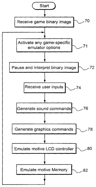
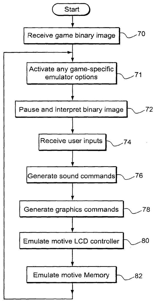
FIG. 2Ashows example steps performed by emulator100. The emulator receives a binary game image (block70) and activates any game-title-specific emulator options (block71). The example emulator100parses and interprets the game binary image (block72) and receives user inputs (block74). The example emulator100generates sound commands (block76) and graphics commands (block78). The example emulator100emulates a native liquid crystal display controller (block80) and native memory (block82).
Example Emulator Functional Modules
FIG. 3shows a breakdown of example illustrative functional modules used to implement theFIG. 2emulator in software. These functional modules include:run game module120,emulate module122,draw_CGB module124,draw_DMG module126,draw_AGB module128,ROM authentication check (“ROM REG”) module130,video module132,VGA module134,buttons module136,sound module138,no write module140,port mode module142,CGB RAM module144,DMA module146,MBC module148,SIO module150,ADDPTRS module152, andtimer module154.
The example functional modules shown inFIG. 3provide various functions that can be called by name from other parts of the emulator code. Each of these functional modules may be implemented with a C or C++ and/or assembler function or other routine in one example implementation. In this particular implementation, the entire executable file (the aggregate of all modules) is designed as a DOS protected mode application that runs with a minimum number of drivers to maximize efficiency.
The run game functional module120loads the game file66into emulated ROM112and then calls the emulate functional module122(FIG. 2Ablock70). The run game module120may also by itself (or in conjunction with an additional function if desired) initialize each of the hardware-handler modules within the emulator100. Emulate functional module122is the main emulation loop and is executed until the user quits the game or other application.
In the example embodiment, the draw functional modules124,126,128perform the task of drawing graphics objects generated by emulator100by sending graphics commands to the graphics adapter62(FIG. 2Ablock78). For example, the draw_CGB functional module124may draw each of 144 color background lines of the COLOR GAME BOY® on the screen and may also by itself (or in conjunction with another module) draw the moving objects after the background has been drawn. The draw_DMG functional module126performs a similar drawing task for original GAME BOY® games and other applications, and the draw_AGB functional module128performs similar drawing tasks for GAME BOY ADVANCE® games and other applications. Example emulator100is capable of emulating any/all of a number of different platforms across the Nintendo GAME BOY® product line.
In this example, the ROM check (“ROM REG”) functional module130is used to check (and/or display) registration data within the game file66. This functional module130is used to ensure, for example, proper authorization on the part of the user before game play is allowed. In another embodiment, the ROM registration module does not do anything regarding user authorization, but just reads the ROM registration data in the game file, sets emulator variables and optionally displays the registration data on the screen. A game file validation function may be included in the ROM registration module to validate the game file, not the user.
The video functional module132is used in the example to transfer character graphics data. The functions in the video module132perform character bitmap translation for any type of write to the character RAM area, whether it is a direct write from the CPU or a DMA transfer. Functions in the video module also handle the RAM bank switching register for character data areas, control and status registers for the LCD controller and palette registers for both CGB and DMG modes. When a game file66instruction calls for a direct memory access data transfer of character information into the GAME BOY® character RAM space, video functional module132performs a character bit map translation into a portion of emulated RAM110to prepare graphics characters for display. The video functional module132may, by itself or in conjunction with another functional module, place appropriate function pointers into appropriate input/output read/write tables for all of the register handling functions that should be performed.
In the example embodiment, the VGA functional module134is used to set the appropriate video mode of the target platform graphics adapter62. In addition, this VGA functional module134may be responsible for transferring full screens of graphics data to VGA graphics adapter62under certain circumstances (e.g., if a hardware-assisted bit BLIT operation is not available on the target platform).
The buttons functional module136is responsible for getting the keypad data from keypad interface54and writing this data into a set of input interface registers that emulate actual hardware interface registers within GAME BOY®, GAME BOY COLOR® and/or GAME BOY ADVANCE®.
The sound functional module138in the example embodiment generates and writes appropriate sound information to the target platform sound adapter58by translating writes to the virtual sound registers to appropriate sound information for the target platform sound adapter (FIG. 2Ablock76). The sound functional module138, by itself or in conjunction with another functional module, may also be used to put function pointers into appropriate input/output, read/write tables for all of the register handling functions performed by the sound functional module.
In this example module, the no write functional module140protects the emulated ROM112from being written to (thus making sure this memory segment is emulated as a read only memory as opposed to a read-write memory during game play). The no write functional module140, by itself or in conjunction with an additional functional module, may place appropriate function pointers into the appropriate input/output read/write tables for all of the register handling functions in the no write functional module.
The port mode functional module142emulates a CPU timer and provides a keypad handler. It has functions that handle the keypad, the timers, and the CPU speed control (e.g., to provide a CPU speed change operation since COLOR GAME BOY® operates twice as fast as GAME BOY® and GAME BOY ADVANCE operates still faster). The port mode functional module142may also set appropriate function pointers or call an additional function module(s) to perform this task. The main function of the CPU timer is to generate CPU interrupts at specified intervals. Registers to specify this interval are handled in the port/mode module. There are a couple of registers that provide real-time views of a free-running counter. These registers can be emulated by returning a random number. This is only a partial emulation (a random number is not a real time value). However, the most common use of these registers by games is to generate a random number by looking at a fast clock at an arbitrary point in time. It is therefore possible to completely satisfy such games by providing a random number as opposed to a real time clock indication. A more accurate emulation can be provided if a game requires the real-time view of the counter actually provided in the native hardware.
The CGB RAM functional module144emulates the COLOR GAME BOY® RAM to provide (additional) emulated RAM110. DMA functional module146performs direct memory access transfers between the various emulated storage resources within emulator100—thereby emulating the GAME BOY® native platform DMA controller. The MBC functional module148emulates the native platform memory bank controller to provide emulated MBC114.
The SIO functional module150emulates a serial input/output port available on a GAME BOY®, GAME BOY COLOR® and/or GAME BOY ADVANCE® platform (e.g., to provide a “game link” operation whereby plural platforms can exchange data over a cable or other communications interface). The ADDPTRS functional module152performs the task of registering various handlers for operation (in particular, it may contain a single function that all hardware support modules call to register their memory/function pointers in an I/O handler table, and accomplishes this by registering pointers for reading and writing to I/O addresses). The timer functional module154implements the virtual liquid crystal display controller103by maintaining an emulated state machine that keeps track of the state and associated timing information of a GAME BOY®, GAME BOY COLOR® and/or GAME BOY ADVANCE® platform. Timer module154thus allows the target platform (which may operate at a completely different speed from the original platform) to maintain a sense of the event timing as those events would occur on the native platform—ensuring that emulator100provides event timings that are consistent with the native platform. Without such timing information, the speed of the application's graphics and/or sound might be different on the emulator100as compared to on the original platform—resulting in an unsatisfying game play experience.
Example Memory Objects And Data Structures
FIG. 4is a block diagram of exemplary memory objects/data structures that emulator100maintains in the random access memory68of the target platform. In some cases, these data structures emulate hardware resources of the native platform. In other cases, these data structures do not correspond directly to any part of the native platform but instead provide support for optimized execution of emulator100.
FIG. 4shows the following exemplary data structures:emulated “read only memory”112,emulated random access memory110,register table160,raw character data buffer162,translator163“bit-map-ized” character data buffer164,background data buffer166,off screen display buffer168,on screen display buffer170,memory bank switched (cartridge) RAM buffer172,object attribute memory buffer173,object index data structure174,CGB RAM buffer175object enable data structure176,page table178,jump table182,various color palettes including a high priority background palette184a, a low priority background palette184b, and an object color palette184cfor emulating COLOR GAME BOY®, andvarious monochrome color (gray scale) palettes for GAME BOY® monochrome game emulation, including a background palette186a, an object0palette186band an object1palette186c.
TheFIG. 4data structures may be globally-defined memory arrays.
The main RAM array110is, in one example, a generic 64K memory array used for any non-paged address space. A CGB buffer175is used to emulate the internal RAM banks for COLOR GAME BOY®. MBC RAM172is used to emulate the random access memory that may be provided within certain game cartridges.
The object index array174may be used for sorting moving objects.
The object enable array176may include a flag for each display line indicating that drawing of moving objects was enabled for that line (flags may be sent/queried as the background is drawn).
Page table178may comprise a 64K table of pointers to the base pointers that handle each address, and may be used to reestablish the program counter on jumps, calls, returns, etc.
Page table178may be used for making pointer adjustments to both the program counter and the stack pointer. In another embodiment, a separate stack table comprising for example a 64K table can be used in a similar manner to page table178, but with a coverage of each base pointer extending one address higher and used to reestablish the base of the stack pointer when it is manually changed.
The ROM pages112may be used to emulate the cartridge read only memory arrays (in the example embodiment, this ROM array is twice as big as the actual ROM pages since the bottom half is always duplicated).
The raw character data array162is used to store raw character data, and the further character data array164is used to store corresponding “bit map-ized” character data. A translator163is used to provide precomputed translation data for translating the raw character data162into the bit mapped character data164. Different sets of pointers are used for each page and addressing mode in this example. The background data buffer166is used to store background data in pages 0 and 1.
The off screen buffer162(which may comprise an entry of 192×160×2) may be used to compose images off screen. This buffer may not be needed when a bit BLIT capability is available within the hardware of the target platform.
Color background palettes184a,184bcomprise two sets of eight palettes, one for high priority background pixels and the other for low priority background pixels. Color object palette184cprovides object palette data to emulate the COLOR GAME BOY® object color palette (one set of eight palettes may be provided). GAME BOY® color palettes186a,186b,186cemulate the monochrome GAME BOY® palettes, with background palette186aproviding four background palette data entries and object palettes186b,186ccomprising object palette data for object0and object1(four entries per palette). The native COLOR GAME BOY® platform has selectable palettes for “colorizing” monochrome GAME BOY® games—and this capability may also be emulated by, for example, changing the color entries within palettes186a,186b,186c. In another embodiment, these palettes186may be preassigned to provide certain default colors (e.g., red objects on a green background).
Jump table182is used to facilitate the parsing and execution of target instructions by emulator100, as is explained below.
Example Emulated Cartridge ROM112
FIG. 5shows an example emulated cartridge ROM112. In the native platform, the cartridge ROM may have a number of banks up to a maximum. Preferred embodiment emulator100emulates each of these banks with a different RAM page112(1),112(2),112(n). In one example embodiment, the number of pages that may be allocated can be fixed (e.g., to a maximum of n=256) to provide static allocation for a four-megabyte game. In another embodiment, the number of ROM pages to allocate can be determined dynamically based on the particular game or other application.
In the example embodiment, the lower 16K in each allocated ROM page112(1), . . .112(n) is duplicated to facilitate page selection and reduce page swapping. A ROM page selection pointer202is used to select the current ROM page, and a ROM page count register204specifies the number of ROM pages loaded for the current game or other application. As mentioned above, the “no write” functional module140is used to protect the ROM space so that inadvertent write instructions within the application and/or emulator100do not succeed in overwriting emulated read only memory112.
As mentioned above, the run game routine120is responsible for loading the game (application) file166into emulated ROM112. Part of this loading operation loads particular compatibility information (seeFIG. 6) and registration data (seeFIG. 7) into the emulated ROM112. TheFIG. 6compatibility information is used to specify whether an application is compatible or incompatible with certain native platforms (e.g., compatibility with the COLOR GAME BOY® mode of emulator100, or whether it can run exclusively on the COLOR GAME BOY® mode). This compatibility information is present in a normal binary game file166to provide instructions to the COLOR GAME BOY® platform; emulator100reads and takes advantage of this information in determining its own emulation mode. The registration data shown inFIG. 7is used in the example embodiment to ensure that game file66is authorized and authentic, and emulator100performs checks similar to those performed by the GAME BOY®, COLOR GAME BOY® and GAME BOY ADVANCE® native platforms (as well as possibly other security checks such as digital signatures, decryption, digital certificates, etc.) to ensure the user has proper authorization.
Example Virtual Liquid Crystal Controller103Implementation
In the example embodiment, emulator100uses an internal state machine to keep track of and emulate the states of an actual GAME BOY®, COLOR GAME BOY® or GAME BOY ADVANCE® platform during emulation operation. The emulator100could execute the instructions within game file66without keeping track of corresponding events within the native platform, but this would lead to loss of real time synchronization. In video game play, the pacing of the audio and video presentation is very important to the game play experience. Playing a game too fast or too slow will tend to destroy the fun of the game It is therefore desirable to emulate a game playing experience that is close to or nearly the same as the game playing experience one would have when running the application on the original native platform.
Emulator100accomplishes this result by maintaining liquid crystal display controller103providing a sequential state machine that is synchronized with event states that would occur on the original native platform. Emulator100synchronizes its operation to the state transitions within this internal state machine to maintain real time synchronization of game play.
FIG. 8shows an example four-state virtual state machine state transition diagram that can be maintained by virtual LCD controller103. These states include:an object attribute memory search state250,a memory transfer state252,a horizontal blanking state254, anda vertical blanking state256.
Additional states (e.g., enable and disable) can also be provided.
In the example embodiment, the sequential progression through all four states250-256comprises a frame that results in the display of a new image on display64. In the native platform, one frame comprises a vertical blanking state256and various repetitions of the hblank, OAM search and OAM transfer states254,250,252dependent on the number of lines (e.g., 144) within a frame. Because the native platform hardware is driven by line scanning operation of a liquid crystal display, so too is preferred embodiment emulator100driven by an emulated state machine that models the same line scanning and other time intervals to ensure proper game timing as the developers of the game intended it and as a user would see and experience a game on the native platform.
Within each line there is an hblank interval and associated state254, as well as an OAM search state250(during which a native platform would search its object attribute memory for objects to be displayed on the next line) and an OAM transfer state252(during which a native platform transfers object character information into a line buffer for display). The table ofFIG. 9Cshows example cycle parameters for theFIG. 8virtual state machine.
The preferred embodiment emulator100emulates a virtual state machine by maintaining the various registers shown inFIGS. 9A and 9B. The registers shown inFIG. 9Agenerally comprise various registers used to keep track of the virtual state and operation of a liquid crystal display controller that is being emulated. In this example, emulator100emulates a liquid crystal display controller using the following registers:LCD cycle counter260(maintains the number of CPU cycles remaining before a transition to the next liquid crystal display controller phase/state should occur),liquid crystal display mode register262(maintains the current phase/state of the liquid crystal display controller including the various states shown inFIG. 8as well as an additional disabled and re-enabled state),a liquid crystal display background enabled flag264(indicates whether the background should be drawn),a liquid crystal display window enabled flag266(indicates whether the current display window is enabled),a liquid crystal display object enabled flag268(indicates that the drawing of moving objects is enabled),a liquid crystal display big object flag270(indicates that objects are sixteen lines high instead of eight),a last object draw line register272(indicates the last line at which a direct memory access to object attribute memory occurred).
TheFIG. 9Btiming registers are used to maintain the various parameters pertaining to the timing parameters associated with theFIG. 8virtual state machine. These registers include:a cycleshblank register274(specifying the number of virtual CPU cycles needed in the horizontal blanking period),a cyclesvblank register276(indicating the number of virtual CPU cycles needed in the vertical blanking period),a cycles OAM (search) register278(indicating the number of virtual CPU cycles needed in the OAM search period),a cycles transfer register280(indicating the number of virtual CPU cycles need in the liquid crystal display data transfer period),a cycles frame register282(indicating the number of virtual CPU cycles needed for an entire frame),a timer ticks register284(this comprises a master game timer and is incremented by interrupt every 1/60thof a second),a cycle counter286(this may be implemented by a local variable within the main emulation functional module122and is used to keep track of the current number of cycles within the frame),a timer target liquid crystal display counter flag288(this is a flag indicating when the cycle counter286reaches 0 in order to control the virtual liquid crystal display controller to transition to the next phase shown inFIG. 8),a fast CPU flag290(a flag indicating that the emulated COLOR GAME BOY® CPU is running in double-speed mode),a do frame flag292(a flag indicating whether emulator100should draw the current and/or next video frame or skip drawing it),a timer cycle counter294(indicates the number of CPU cycles remaining before a timer interrupt should be asserted),a timer threshold register296(indicates the number of CPU cycles corresponding to the current timer interrupt period),a timer enable register298(a flag indicating that timer interrupts are enabled).
FIG. 10is a flow diagram of an example emulated liquid crystal display controller103. This flow diagram uses the various registers shown inFIGS. 9A and 9Bto implement theFIG. 8state machine. TheFIG. 10flow diagram has been simplified for purposes of illustration; additional operations may occur in an actual implementation. As shown inFIG. 10, the virtual state machine is initialized with an initial state by updating an express or implied state counter (state may be explicitly stored in register262or it may be implied through inline code for efficiency purposes if desired) (block302). Then, the cycle counter register286is loaded with an appropriate number of cycles from the one of registers274,276,278,280corresponding to the current state of the state machine (block304, seeFIGS. 8and9C). The cycle counter286is continually decremented at the emulated CPU rate (block306) (as determined, for example, by the fast CPU flag290) in response to timer ticks284. This cycle counter286is continually compared with zero (decision block308) to determine whether the current state is over. When the cycle counter has been decremented to zero (the “=” exit to decision block308), the emulated LCD controller103transitions to the next state of the virtual state machine (seeFIG. 8) (block310). In the example embodiment, the cycle counter register is decremented by a fixed amount for each CPU instruction emulated. The effect of double-speed CPU operation is accomplished by loading the cycle counter with twice the number for each LCD controller phase than would be loaded for single-speed operation. So the cycle counter gets decremented at the same rate (which is determined by the speed of the host CPU), but the CPU can run through twice as many cycles per LCD phase in double-speed mode. Since the game speed is governed by throwing in an appropriate wait time once per frame in the example embodiment, the game speed is correct for both fast and slow modes, but in fast mode the CPU can do twice as much work.
If the next state is vertical blanking (“yes” exit to decision block312), then emulator100determines whether it is running behind (e.g., by determining the amount of time until the next timer interrupt is going to occur). Preferred embodiment emulator100tries to maintain the sixty frames-per-second screen update rate of the native platform. However, in one particular embodiment, it is not always possible (e.g., depending upon the particular game of other application being executed) to maintain a sixty frame-per-second rate on a slow target platform. In that example embodiment, emulator100dynamically scales back to a slower, thirty frame-per-second rate by setting the do-frame flag292(“yes” exit to decision block314, block316) which will have the result of entirely skipping the drawing of the next frame. In that example embodiment, this frame-skipping operation does not skip execution of any instruction from game file66. All such instructions are executed by virtual microprocessor core102in order to continually maintain and update appropriate state information. Furthermore, this frame-skipping operation does not have the result, in the embodiment, of partially rendering the frame being skipped. For example, there is no selective execution of certain graphics commands in a command buffer depending on whether or not the emulator is falling behind. In that example embodiment of emulator100, the only operations that are skipped are internal emulator100operations of transferring graphic information to the VGA graphics adapter62and updating the display64—resulting in the frame either being rendered or not being rendered. Since the GAME BOY platforms operate to render an entire new frame each 1/60thof a second “from scratch”, there is no need to partially render a frame for use in generating a next frame, and such a partial rendering would tend only to degrade speed performance and generate uncertain image results. A maximum of every other frame may be skipped in the example embodiment since using a frame update rate of less than 1/30thof a second would noticeably degrade image quality.
In a further embodiment, the “dynamic-scaling” feature is omitted from the emulator100to allow better emulation of transparency-based images. It turns out there are some games that achieve transparency effects by enabling and disabling the visibility of entities on the screen at a 30 fps rate (on for one frame, off the next). Allowing the emulator to skip “as needed” between 30 fps and 60 fps causes undesirable flickering in such games. In this alternate configuration, the emulator100may draw frames at either a fixed 30 fps (skip drawing of every other frame) or a fixed 45 fps (skip drawing of every third frame). Running at 30 fps causes the object to either always be visible or never be visible, depending on which phase you hit on. This is less than perfect emulation, but actually is the best solution for at least some games. For example, the 45 fps rate is currently used in certain games to make characters blink when they are hit by an enemy. Running at 45 fps (which provides acceptable game speed in certain games but not many other CGB games) allows you to alternate between visible and invisible and provides a good flickering character. If the emulator could draw at 60 fps, none of these problems would exist, but slow target hardware does not permit this. Luckily, 30 fps provides good game play for most games. It is possible to modify a few bytes (the “game code”, which the emulator does not use) in the ROM registration area of the game file to tell the emulator what frame rate to use. There may be other game-specific emulation parameters put into the game file in the future.
Example Instruction Parsing/Execution By Virtual Microprocessor Core102
In the example embodiment, the virtual microprocessor core102interprets the binary instruction formats of game file66(FIG. 2Ablock72). As mentioned above, the game file66binary instruction formats in the example embodiment are compiled for execution by a Z80 microprocessor of the native platform—whereas the target platform on which emulator100runs may be any microprocessor (e.g., an Intel 8086 family microprocessor). In the example embodiment, the virtual microprocessor core102may include a binary instruction format parser implemented as a jump table (e.g., C or C++ “case” statement) that parses the binary op code portion of the incoming instruction and jumps to appropriate code that performs one or a series of steps that will cause emulator100to emulate the operation of that instruction.FIG. 11shows an example jump table flow based on the jump table182(which may be implemented as inline code if desired).
Those skilled in the art will understand that different native instructions can be emulated in different ways depending upon the particular instruction.FIG. 12shows an example flow diagram for emulation of an example “no operation” (NOP) instruction. In thisFIG. 12example, an op code of “00” parsed by theFIG. 11process results in transferring control to theFIG. 12process for emulating the “no operation” instruction. On the native platform, a “no operation” instruction results in nothing happening (wait) for a CPU cycle. Within emulator100, in contrast, certain tasks are performed in response to such a “no operation” instruction. For example, an emulated program counter (which is different from the target platform program counter and is used to emulate the program counter of the native platform) is incremented (block322), and the cycle counter is decremented (see block306,FIG. 10). As shown inFIG. 10, if the cycle counter is not greater than zero, a “timer” function is called to perform the steps of blocks310-316shown inFIG. 10. If the cycle counter is still greater than zero, then control returns to theFIG. 11operation to parse the next op code (block324).
Some games and other applications make extensive use of “no operation” loops to maintain game timing Somewhat surprisingly, such “no operation” loops can cause emulator100to run very slowly. To avoid this particular issue, it is possible for emulator100to include a dynamic code analyzer that “looks ahead” to the next few instructions surrounding a “no op” instruction to determine whether the game file66includes a “no op” loop. If emulator100determines that such a loop is present, then the emulator may intelligently use events other than a wait loop (e.g., setting a timer and waiting for it to expire, or relying on the virtual liquid crystal display controller103) as alternate means for providing the requisite “wait loop” timing. This optimization can result in increased efficiency by preventing the emulator100from becoming bogged down with “no operation” wait loops. In other embodiments, no NOP-reduction analysis is implemented, and the only such technique implemented is to detect whether a loop was waiting for a transition of the LCD machine and automatically force the transition. The problem is that such a technique may work for some games, but could cause some games to malfunction.
Example Memory Access Instruction Emulation
FIG. 13shows an example page table178within the context of a memory map that also includes emulated RAM110,172,175and emulated ROM112. This page table178is used in the example embodiment to process memory access commands within game file66. In this example embodiment, some memory access (read or write) commands can be executed by performing the requested read or write operation on a specified location within memory. In such cases, page table178includes a memory pointer specifying a corresponding memory location—remapping various read/write locations into other locations as defined within the emulator100(seeFIG. 14, blocks332,334,336). In some cases, a read or write to a particular memory location will trigger the performance of a sequence of steps by emulator100. As an example, a read by the game file66of a game controller input register of the native platform may cause emulator100to execute a “key” function in order to poll the keypad interface54and get a user controller input value. The preferred embodiment page table178handles this situation by providing a zero-valued memory pointer within page table178(FIG. 14, block334) that causes the emulator to reference an associated “key” function pointer—resulting in the calling of a “key” function (FIG. 14, block338). In this way, page table178efficiently maps native instruction memory accesses to the same or different memory locations within emulated memory and/or to calling a function that emulates a result which would occur on the native platform in response to such a memory access command.
Also as shown inFIG. 13and alluded to above, the emulated random access memory172,175,110and the emulated read only memory112may include multiple copies of the same information within the target platform random access memory68in order to provide more efficient paging and corresponding reduction in processing time.
FIG. 15shows implementation detail for one detailed implementation of page table178. In this example, the page table may comprise two different tables178a,178b—one for read memory accesses and one for write memory accesses. Each of these tables may be 64 kilobytes (or other convenient size). All memory accesses by virtual microprocessor core102are performed via these tables178a,178b. The code that is reading or writing first looks to see if there is a non-null value in the “PTR” element for the desired address. The “PTR” element is a pointer to the pointer that defines the base of the target platform memory array that applies for the desired address. If there is a non-null “PTR” value, de-referencing “PTR” and adding the desired address will get emulator100to the target platform address to read/write. If, on the other hand, the “PTR” value is null, that means that there is a handler function defined for reading/writing to the desired address. The handler function can be called via the “FUNCT” element of the appropriate table.
Different functions can be called for reading from and writing to the same address in this example arrangement, and different pointers may be used reading from and writing to the same address. Similarly, a read operation with respect to a particular native address may cause a read from an active “PTR” memory mapped value whereas a write operation to the same address can invoke a handler function—or vice versa. The flexibility provided by this arrangement simplifies the architecture of emulator100while providing an efficient way to execute instructions from game file66.
Emulated Microprocessor Registers
FIG. 16shows example emulated registers within the virtual microprocessor core102. In this example, the native (e.g., Z80) microprocessor registers are emulated with random access memory values within the target platform RAM68and/or actual registers internal to the target platform CPU. For example, it may be desirable to map certain emulated native microprocessor registers to target microprocessor registers for efficiency purposes (e.g., to map a program counter350to a general purpose register within the target platform CPU).
In the example embodiment, the program counter or program pointer350may include a current base pointer for the program counter as well as an offset portion. Similarly, a stack pointer352may include a base pointer for an emulated stack pointer to which may be added an offset (e.g., in a target platform register). Virtual microprocessor core102may further include a set of emulated native platform flags354including:a carry flag354a,a half-carry flag354b,an add sub flag354c,a zero flag354d.
In the example embodiment, emulated flags354are not in the same bit positions as the native platform flags, but rather they are in positions used by the target platform processor. This allows emulator100to pass “virtual” flags to the target platform processor before performing operations that effect the flags. The target platform flags are retrieved into the virtual flag data structure354after the operation is performed.
In the example embodiment, the various native platform general purpose registers are defined in three separate data structures as bytes (block356), words (block358) and long words (block360). The three structures356,358,360are bundled into a union so that emulator100can access a particular register as a byte, a word or a long word as needed. In the example embodiment, the program pointer350is not included because it is maintained as a C character pointer for maximum efficiency. The program counter or pointer can be declared as a local variable in the main emulation function122, and the compiler preferably implements the program pointer350as a register in the target platform CPU as described above.
Some additional optimizations are possible when accessing the emulated registers shown inFIG. 16. For example, the HL register within the native platform CPU is often used as an index register. AsFIG. 17shows, it is possible for virtual microprocessor core102to “look ahead” by determining whether the indexed address is for a special hardware location in response to a write to the HL register (decision block370)—and to access page table178immediately in response to such an indexed address so that the corresponding memory pointer and/or function are available when a further instruction comes along that uses the HL register contents for an indexed operation (block372). This optimization can save processing time. Indirect accesses via HL or any other 16-bit register (BC or DE) are all handled by referring to the I/O read/write handler tables in the example embodiment. One “look-ahead” technique the preferred embodiment emulator uses is the “prefetch queue” implemented by always fetching four bytes into a 32-bit target platform register each time. The low-order byte is the opcode the emulator is after, but many opcodes require one or two subsequent bytes as data or extended opcode. By having four bytes in a register, any opcode handlers that need subsequent bytes already have them in a CPU register.
Referring once again toFIG. 16, the virtual microprocessor core102further includes a set of interrupt vectors and an interrupt master enable flag that are used to emulate the interrupt structure within a GAME BOY®, GAME BOY COLOR® and/or GAME BOY ADVANCE® native platform. This interrupt vector (when enabled by the interrupt master enable flag) can be read to determine what portion of emulator100caused a particular interrupt (e.g., vblank, the liquid crystal display controller, a timer, button depression, or serial input/output). Emulator100provides an emulated interrupt controller that emulates the actual native platform interrupt structure in controller to maintain compatibility and event-driven functionality of game file66.
Example Keypad Emulation
As shown inFIG. 18, preferred embodiment emulator100provides keypad emulation104in the example embodiment through the use of certain data registers/flags including:a buttons direction register380that maintains the data for emulated direction keys,a buttons buttons register382that maintains the data for the emulated control buttons, anda buttons changed flag384that indicates that the button data has been changed.
In one example embodiment, the buttons direction register380and the buttons buttons register382encode various button parameters in certain bit positions as shown inFIG. 18. As mentioned above, the buttons functional module136shown inFIG. 3may be used to retrieve inputs from keypad interface54and load them into theFIG. 18data structures for reading by virtual microprocessor core102. These data structures and associated functionality emulate the hardware control input controller of the native platform by duplicating the register interface of the native platform in software. Target platform controller device56may be any of a variety of different configurations including, for example, an SNES handheld controller, a keypad, or any other input device capable of interacting with a user. A “parallel port” register or indicator388may be used to define the type of keypad interface54(e.g., SNES controller adapter or keyboard) that will be used for the controller input on the target platform.
Miscellaneous Additional Virtual Microprocessor Data Structures/Functions
FIGS. 19A and 19Bshow example additional virtual microprocessor data structures. These data structures are used to provide a variety of different additional functionality in the example embodiment of emulator100.
As shown inFIG. 19A, preferred embodiment emulator100may include one or more game-specific emulation options that go into effect for particular games or other applications (FIG. 2Ablock71). As one example, an “options” data structure402may specify particular functions and/or features that could be activated selectively depending upon the particular application or game being supplied by game file66. Such game-specific emulation options can improve efficiency by tailoring the operation of emulator100for particular applications or games on a dynamic, as-needed basis. While in some embodiments it would be best to avoid using game-specific options, in other examples it might be desirable to use such game-specific options to increase efficiency and/or functionality.
As shown inFIG. 19A, one game-specific option might be using a single CGB_RAM memory pointer. Another game-specific option is the 30/45 fps frame rate option described previously. Other game-specific options are possible.
FIG. 19Aalso shows a “DMG only” flag404that is used in the example embodiment to indicate that the loaded game file66is COLOR GAME BOY® incompatible. This DMG only flag404(which is set or unset depending on the compatibility modes shown inFIG. 6) is used to determine whether COLOR GAME BOY® functionality of emulator100is enabled or disabled. It is also possible to provide a flag indicating that the stack pointer is allocated to a particular region of memory (e.g., fixed emulated COLOR GAME BOY® RAM). The flag that indicates that the stack pointer is pointing to a particular region of memory (fixed CGB RAM) is not a game-specific option in one example embodiment, and is set dynamically by the emulator100.
A rumble pack flag406is used in the example embodiment to indicate whether the loaded game file66supports the rumble pack feature of certain native platform games.
The TSR interrupt register408in the example embodiment specifies the number of the DOS interrupt used for host-to-emulator communication.
A DMA source register410specifies a source address for emulated direct memory access operations, and a DMA destination register412specifies a destination address for emulated direct memory access operations. A memory base pointer414specifies a base pointer for non-paged memory110.
Referring toFIG. 19B, a register file including for example, various native platform registers emulated in software (RAM locations) is shown. Such registers include, for example, sound control registers (“NR10-NR52”), a liquid crystal display controller register having the bit assignments shown, and a status register STAT having the bit assignments shown.
In terms of sound emulation, certain information written to the sound control registers may be straight-forwardly translated and passed on to the target platform sound adapter58using the particular API used by that sound adapter. Other sound generation commands are peculiar to the GAME BOY®, GAME BOY COLOR® and GAME BOY ADVANCE® native platforms, and need to be emulated using sound-producing functions. These sound-producing functions take advantage, as much as possible, of the target platform sound generation capabilities, but typically need to provide additional state information (e.g., implementation of a sound-generation state machine) in order to ensure sound timing synchronization. Maintaining real time sound timing sound synchronization is especially important with voices—which will sound unnatural if played back too fast or too slow. Unfortunately, voice reproduction may be difficult to achieve since the strict CPU timing necessary to play back voice takes up too much time in itself, and may not be possible to perform on a low-resource target platform. Games that rely on voice playback for a satisfactory game play experience may have to be excluded. In the example embodiment, the sound module translates writes to the virtual sound registers to appropriate sound information for the target platform sound adapter. If the sound library used does not provide for automatic termination of sounds after specified durations, then the emulator100may also be provided with the capability to terminate sounds at appropriate times.
Graphics Emulation
As described above, a graphics emulation108portion of emulator100in the example embodiment receives commands from the virtual microprocessor core102and performs responsive graphics tasks. This graphics emulation functionality performed by block108supplies capabilities normally supplied by the graphics acceleration hardware of the native platform.
One way to provide such graphics emulation108would be to nearly exactly implement, in software, each of the hardware structures of the native platform's graphics circuitry. This is not necessarily the best approach, however, since it may be more efficient to perform certain graphics-related tasks differently in software.FIG. 20shows an example of how the efficiency of preferred embodiment emulator100is enhanced by handling character data differently than the way it is handled in the native platform.
In theFIG. 20example, a pre-computed translation table163is used to translate “raw” character data within an array162into a “bit mapped-ized” character data format for storage into buffer164.FIGS. 21 and 22further illustrate this feature. TheFIG. 21representation shows a portion of the “raw” character data buffer162storing the character data bit planes as they are typically maintained by the native platform. Pre-computed translator163translates this raw character data representation into a differently-ordered and organized, bit mapped character data representation more like the format found in a conventional bit map (.bmp) file. This character data reorganization is useful in minimizing processing time required to output character graphics data to the video adapter62. TheFIG. 22“bit mapped-ized” representation is more compatible with VGA and other commonly-used video adapter hardware, and the pre-computation of translator163allows this data reorganization to occur in a straight forward manner in advance of the time when the graphics data is sent to the graphics adapter62.
FIG. 23shows a number of example graphics object pointers used by graphics emulation block108, including:window x, window y registers450,452specifying the coordinates of the display window (these coordinates may be copied from the memory [wx], memory [ly] values at the top of each frame),a window source y register454specifying the y coordinate for the source data for a window (this may start at zero at the top of the window),a background base pointer456that stores the base pointer for the current background RAM area (moves between background1and background2, pages zero and one),a background pointer bank zero and background pointer bank one register458,460specifying the base pointer for the current background RAM page zero and page one (these registers move between background1and background2areas),a window pointer bank zero register and a window pointer bank one register462,464(these registers specify base pointers for the current window RAM page zero and one respectively (they move between pages zero and one)),a character base pointer register466specifying the base pointer for the current character RAM area (moves between pages zero and one),a character RAM base pointer467specifying the base pointer for the current internal COLOR GAME BOY® RAM area175(0xC000-0xE000),a character bit mapped base pointer468specifying the base pointer for the “bit map-ized” character data164(this pointer moves between pages zero and one),a memory bank controller RAM base pointer470specifying the base pointer for the current cartridge RAM page172,a character bit map index bank zero pointer and a character bit map index bank one pointer472,474used as pointers to pre-sort an (addressing mode appropriate) array of pointers to the bank zero (bank one) “bit map-ized” character data.
FIG. 24shows an example illustration of a preferred embodiment emulated object attribute memory173. In this example, the native platform includes an object attribute memory that maintains pointer and other information relating to characters to be displayed on the next frame. Preferred example embodiment emulator100includes an emulated object attribute memory173including an array of up to 40 objects each including y (vertical position), x (horizontal position), character (identifier) and attribute field. The bit-encoding of the attribute field information is also shown inFIG. 24. An OAM base pointer476is used to function as a pre-allocated pointer to the emulated object attribute memory object173.
FIG. 25shows an example video memory arrangement including an off screen memory buffer168and an on screen memory buffer170. In the example embodiment, the off screen memory buffer168is defined to be larger than the display size of the native platform. For example, the display size of a GAME BOY® or COLOR GAME BOY® is 160 pixels by 144 pixels high. In the example embodiment, off screen memory buffer168is defined to be 192 pixels wide by 160 pixels high—leaving additional memory locations on all sides of the screen size buffer. A buffer zone of sixteen bytes or eight bytes is useful in improving efficiency. The use of screen memory buffers larger than screen size is an attempt to increase graphic drawing efficiency by eliminating clipping calculations and using the hardware BitBlt to transfer a subset of the memory buffer to displayed video memory. It may be desirable to use two off-screen buffers and one on-screen buffer in a classic “double-buffering” technique. Emulator100may draw to one buffer until it is complete, then switch to the other buffer. On the target hardware's vertical retrace interrupt, the emulator100copies the last-completed buffer to the on-screen area via BitBlt. This works well when a way is provided to implement the vertical retrace interrupt. As mentioned above, the “buffer zone” in the memory buffer is used to eliminate clipping calculations.
The example embodiment emulator100uses a hardware-assisted bit BLIT operation to copy the contents of the screen size buffer into on screen buffer170. Such a bit-BLIT hardware-assisted operator can increase transfer times without corresponding increases in overhead. If a bit BLIT operation is not available, then a conventional direct memory access or other memory transfer can be used instead. In the example embodiment, a STPC TARGET register478is used to specify whether a bit BLIT engine of the target platform is available and can be used (if one is not available, then a conventional memory copy function can be used instead).
FIG. 26shows some example additional graphics mode selectors used by emulator100in the preferred embodiment, including:a selector graphics engine register480that selects protected-mode memory for the graphics engine registers,a selector off screen register482that selects protected mode memory for the off-screen video memory buffer168(two such selector registers can be used to indicate which one of two double buffered buffers is currently being drawn, with an index variable indicating this), anda selector on screen register484that selects protected mode memory for the on-screen video memory buffer170.
FIG. 27shows an example screen layout of display64showing that the emulated display provided by on-screen buffer170may be smaller than the actual display area of display64. In one example embodiment, the graphics adapter62and associated display64may provide a resolution of 320 pixels by 200 pixels, whereas emulator100produces an emulated image of 160 pixels by 144 pixels. Emulator100uses only a subset of display64to display emulated images in order to preserve aspect ratio.
FIG. 28shows an example set of graphics adapter62control constants that may be set to the VGA graphics adapter in order to set the graphics adapter's mode for use with emulator100. Emulator100may be hard-coded to a particular graphics mode (320×200×16), an 8-bit color mode, or other mode available on the target hardware. If the 320×200×16 color mode (VESA mode 0x10E) works on a particular target platform, emulator100may use this mode exclusively—and there will be no need for different control constants for the VGA.
FIG. 29shows example graphics engine register indices and associated example values. A screen pitch of 384 may also be defined as a constant in the example embodiment.
Example Color Palette Processing
In the example embodiment, the handling of color palettes can lead to efficiency problems. In the example native platforms, graphics characters are represented in a color lookup table (CLUT) format (i.e., the graphics characters themselves include a reduced number of bits that are used to look up a color value in a color palette for display). SeeFIG. 21. The example COLOR GAME BOY® native platform can display 56 colors on the screen nominally (eight palettes of four colors each for background, and eight palettes of four colors each for object characters minus transparency). It would seem therefore that with only 56 simultaneous colors on the screen at any one time, it would be possible to use a 320×200×8-bit VGA mode (13H) which would provide 256 different colors on the screen at once (much more than 56 colors). One possibility would be to simply add an offset into a VGA palette when using 8 bits of color. However, certain game developers for the COLOR GAME BOY® native platform change color palettes during horizontal blanking periods to achieve greater color variety on the screen. To emulate for these particular games, it is necessary to provide more than 256 colors on the screen at a time. A mode such as the VESA standard (320×216 bits) provides 65,000 different colors (RGB 565)—about twice as much as the 32,000 colors the GAME BOY COLOR® is capable of displaying. Thus, this video adapter mode is adequate for even applications that change their color palettes in the middle of a frame—but using this mode doubles the amount of information that must be sent to the video memory per frame and costs processing time. Moreover, it also requires emulator100in the preferred embodiment to map color information (4 bits) into 32,000 colors. The 16-bit color resolution makes it desirable for emulator100to write 16-bit color palette information into the video adapter62. This, in turn, necessitates a memory array of 16-bit numbers associated with the various color palettes. The color palettes (seeFIG. 4) can be accessed on a character-by-character basis, using pointers to apply color information to the “bit map-ized” character data164before the data is written to the display buffer168.
While the invention has been described in connection with what is presently considered to be the most practical and preferred embodiment, it is to be understood that the invention is not to be limited to the disclosed embodiment, but on the contrary, is intended to cover various modifications and equivalent arrangements included within the scope of the appended claims.
Claims
- A method of adapting operation of an emulator, the method comprising: executing, on a processor, an emulator capable of running a plurality of different binary applications, each of said plurality of different binary applications having an associated identity;recognizing, by the processor, an associated identity of a binary application for running by the emulator;the processor accessing a stored data structure that specifies a function(s) and/or feature(s) for selective activation depending upon the recognized identity of the binary application;automatically adapting, by the processor, a behavior of the emulator to the binary application based on the specification of the function(s) and/or feature(s) depending on the recognized identity of the binary application;and generating, by the processor, an audio visual presentation using the adapted behavior of the emulator running the binary application.
- The method of claim 1 wherein recognizing includes inspecting the binary application.
- The method of claim 1 wherein automatically adapting includes activating game-title-specific emulator options.
- The method of claim 1 further including dynamically tailoring the operation of the emulator for particular applications or games.
- An emulation system comprising: a processor executing an emulator capable of running a plurality different binary applications, each of said plurality of different binary applications having an associated identity;a data storage coupled to the processor, the data storage storing a data structure that specifies an emulator function(s) and/or feature(s) for selective activation depending upon a recognized identity of a binary application commanded to be run by the emulator;the processor being configured to recognize an identity of a binary application commanded to be run by the emulator and automatically adapt a behavior of the emulator to the binary application based on the stored data structure specification of a emulator function(s) and/or feature(s) for selective activation depending upon the recognized identity of the binary application commanded to be run by the emulator;the processor being further configured to generate an audio visual presentation using the adapted behavior of the emulator.
- The system of claim 5 wherein the processor is configured to inspect the binary application to recognize the application.
- The system of claim 5 wherein the processor is configured to activate game-title-specific emulator options.
- The system of claim 5 wherein the processor is further configured to tailor the operation of the emulator for particular applications or games.
- The system of claim 5 wherein the processor is further configured to selectively skip frames in order to maintain speed of the application when the application becomes graphically intensive.
Disclaimer: Data collected from the USPTO and may be malformed, incomplete, and/or otherwise inaccurate.