U.S. Pat. No. 9,537,357
WIRELESS SOUND CHARGING METHODS AND SYSTEMS FOR GAME CONTROLLERS, BASED ON POCKET-FORMING
AssigneeEnergous Corporation
Issue DateMay 8, 2014
Illustrative Figure
Abstract
The present invention provides wireless charging methods and systems for powering game controllers. The methods and systems may include one or more transmitters and one or more receivers. In some embodiments the transmitters and receivers may be embedded to game console and game controllers, respectively. In other embodiments, the transmitters and receivers may be connected as a separate device to the game console and game controllers, respectively. The method may include wireless power transmission through suitable techniques such as pocket-forming utilizing sound waves.
Description
DETAILED DESCRIPTION OF THE DRAWINGS Definitions “Pocket-forming” may refer to generating two or more sound waves which converge in 3-d space, forming controlled constructive and destructive interference patterns. “Pockets of energy” may refer to areas or regions of space where energy or power may accumulate in the form of constructive interference patterns of sound waves. “Null-space” may refer to areas or regions of space where pockets of energy do not form because of destructive interference patterns of sound waves. “Transmitter” may refer to a device, including a chip which may generate two or more SW signals, at least one SW signal being phase shifted and gain adjusted with respect to other SW signals, substantially all of which pass through one or more transducers such that focused SW signals are directed to a target. “Receiver” may refer to a device including at least one antenna element, at least one rectifying circuit and at least one power converter, which may utilize pockets of energy for powering, or charging an electronic device. “Adaptive pocket-forming” may refer to dynamically adjusting pocket-forming to regulate power on one or more targeted receivers. DESCRIPTION OF THE DRAWINGS In the following detailed description, reference is made to the accompanying drawings, which form a part hereof. In the drawings, which may not be to scale or to proportion, similar symbols typically identify similar components, unless context dictates otherwise. The illustrative embodiments described in the detailed description, drawings and claims, are not meant to be limiting. Other embodiments may be used and/or and other changes may he made without departing from the spirit or scope of the present invention. As background, a sound waveform has the same characteristics as that of an electrical waveform which are Wavelength (λ), Frequency (f) and Velocity (m/s). Both the sounds frequency and wave shape ...
DETAILED DESCRIPTION OF THE DRAWINGS
Definitions
“Pocket-forming” may refer to generating two or more sound waves which converge in 3-d space, forming controlled constructive and destructive interference patterns.
“Pockets of energy” may refer to areas or regions of space where energy or power may accumulate in the form of constructive interference patterns of sound waves.
“Null-space” may refer to areas or regions of space where pockets of energy do not form because of destructive interference patterns of sound waves.
“Transmitter” may refer to a device, including a chip which may generate two or more SW signals, at least one SW signal being phase shifted and gain adjusted with respect to other SW signals, substantially all of which pass through one or more transducers such that focused SW signals are directed to a target.
“Receiver” may refer to a device including at least one antenna element, at least one rectifying circuit and at least one power converter, which may utilize pockets of energy for powering, or charging an electronic device.
“Adaptive pocket-forming” may refer to dynamically adjusting pocket-forming to regulate power on one or more targeted receivers.
DESCRIPTION OF THE DRAWINGS
In the following detailed description, reference is made to the accompanying drawings, which form a part hereof. In the drawings, which may not be to scale or to proportion, similar symbols typically identify similar components, unless context dictates otherwise. The illustrative embodiments described in the detailed description, drawings and claims, are not meant to be limiting. Other embodiments may be used and/or and other changes may he made without departing from the spirit or scope of the present invention.
As background, a sound waveform has the same characteristics as that of an electrical waveform which are Wavelength (λ), Frequency (f) and Velocity (m/s). Both the sounds frequency and wave shape are determined by the origin or vibration that originally produced the sound but the velocity is dependent upon the medium of transmission (air, water etc.) that carries the sound wave. Audio Sound Transducers include both input sensors, that convert sound into and electrical signal such as a Microphone and output actuators that convert the electrical signals back into sound such as a loudspeaker.
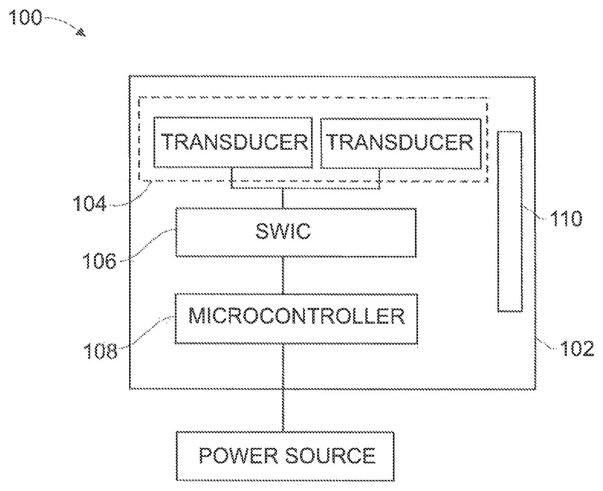
FIG. 1shows an example of a transmitter100that can be used for pocket-forming utilizing a sound transducer. In this embodiment, transmitter100may be used to provide wireless power transmission. Transmitter100may include a housing102having at least two or more antenna elements104, at least one SW integrated circuit (SWIC106), at least one digital signal processor (DSP) or micro-controller108, and one communications component110. Housing102can be made of any suitable material which may allow for signal or wave transmission and/or reception, for example plastic or hard rubber. Transducer elements104may include suitable transducer types for operating in frequency bands such as 10 KHz to 50 KHz as these frequency bands are ideally suited for sound transmission in wireless power transmission. Transducer elements104may include piezoelectric transducers and similar such transducers capable of producing controlled sound waves that are directed to electronic device ready to be powered. Micro-controller108may then process information sent by a receiver through communications component110for determining optimum times and locations for pocket-forming. Communications component110may be based on standard wireless communication protocols which may include Bluetooth, Wi-Fi or ZigBee. In addition, communications component110may be used to transfer other information such as an identifier for the device or user, battery level, location or other such information. Other communications component110may be possible which may include radar, infrared cameras or sound devices for sonic triangulation for determining the device's position.
FIG. 2shows an example of a receiver200that can be used for pocket-forming. In this embodiment, receiver200may be used for powering or charging an electronic device. Receiver200may also include a housing202having at least one sensor element204, one rectifier206, one power converter208and one or more communications component210. Housing202can be made of any suitable material which may allow for signal or wave transmission and/or reception, for example plastic or hard rubber. Housing202may be an external hardware that may be added to different electronic equipment, for example in the form of cases, or can be embedded within electronic equipment as well. Sensor element204may include suitable sensor types for operating in frequency bands such as those described for transmitter100fromFIG. 1. Sensor element204may include multiple sensors in an array to better receive the power sound waves from the transmitter. Multiple sensors are beneficial in receivers or on the electronic device itself where there may not be a preferred orientation during usage or whose orientation may vary continuously through time, for example a smartphone or portable gaming system. On the contrary, for electronic devices with well-defined orientations, for example a two-handed video game controller, there might be a preferred orientation for the sensor element which may dictate a ratio for the number of sensors used on a given electronic device to be charged.
Suitable sensor elements204are microphone types. A sound transducer that can be classed as a “sound sensor”. This is because it produces an electrical analogue output signal which is proportional to the “acoustic” sound wave acting upon its flexible diaphragm. This signal is an “electrical image” representing the characteristics of the acoustic waveform. Generally, the output signal from a microphone is an analogue signal either in the form of a voltage or current which is proportional to the actual sound wave. The most common types of microphones available as sound transducers are Dynamic, Electret Condenser, Ribbon and the newer Piezo-electric Crystal types. This may further prove advantageous as a receiver, such as receiver200, where the sensor element204is a dynamic moving-coil microphone sound transducer to optimize wireless power transmission. Rectifier206may include diodes or resistors, inductors or capacitors to rectify the alternating current (AC) voltage generated by sensor element204to direct current (DC) voltage. Rectifier206may be placed as close as is technically possible to sensor element204to minimize losses. After rectifying AC voltage, DC voltage may be regulated using power converter208. Power converter208can be a DC-DC converter which may help provide a constant voltage output, regardless of input, to an electronic device, or as in this embodiment to a battery212. Typical voltage outputs can be from about 5 volts to about 10 volts.
In some embodiments, power converter208may include electronic switched mode DC-DC converters which can provide high efficiency. In such a case, a capacitor (not shown) may be included before power converter208to ensure sufficient current is provided for the switching device to operate. When charging an electronic device, for example a phone or laptop computer, initial high currents which can break-down the operation of an electronic switched mode DC-DC converter may be required. In such a case, a capacitor (not shown) may be added at the output of receiver200to provide the extra energy required. Afterwards, lower power can be provided, for example 1/80 of the total initial power while having the phone or laptop still build-up charge. Lastly, a communications component210may be included in receiver200to communicate with a transmitter or to other electronic equipment. Such a communications component210may be based on standard wireless communication protocols which may include Bluetooth, WI-Fi or ZigBee similar to communications component110from transmitter100.
FIG. 3illustrates two embodiments including a receiver200that can be used for pocket-forming in game controllers300.FIG. 3Athen shows a first embodiment where game controller302may include a receiver200, as the one described inFIG. 2, embedded in its front side. Receiver200may include an array of sensor elements204strategically distributed on the grid area shown inFIG. 3A. The number and type of sensor elements204may be calculated according to the game controller's design.
FIG. 3Bshows a second embodiment where game controller304may include receiver200, as the one described inFIG. 2. However, in this embodiment, game controller304may need an additional case306to provide wireless power to game controller304. Case306may be made out of plastic rubber or any other suitable material for cases, and it may include an array of sensor elements204located on the back side of case306which number and type may be calculated according to the game controller design, as shown inFIG. 3B. Case306may also be connected to game controller304through a cable308, or in other embodiments game controller304may just be hooked up to case306(not shown), to provide wireless power.
FIG. 4illustrates a first embodiment for providing wireless power transmission400to game controllers300, using pocket-forming. Transmitter100may be located at the ceiling of a living room pointing downwards, and may transmit controlled sound waves402which may converge in 3-d space. The amplitude of the sound waves402may be controlled through phase and/or relative amplitude adjustments to form constructive and destructive interference patterns (pocket-forming). Pockets of energy404may be formed at constructive interference patterns and can be 3-dimensional in shape whereas null-spaces may be generated at destructive interference patterns. A receiver200, embedded or attached to game controllers300, may then utilize pockets of energy404produced by pocket-forming for charging or powering an electronic device, for example a game controller302or game controller304, and thus effectively providing wireless power transmission400.
In an embodiment, transmitter100may include a housing102where at least two or more transducer elements104, at least one SW integrated circuit (SWIC106), at least one digital signal processor (DSP) or micro-controller108, and one communications component110may be included. Transmitter100may also include a local oscillator chip for converting alternating current (AC) power to SW signals. Such SW signals may firstly be phase and gain adjusted through an SWIC106proprietary chip, and then converted to SW signals402via transducer elements104. On the other hand, receiver200may include a housing202where at least one sensor element204, at least one rectifier206and at least one power converter208may be included. The receiver200communicates with transmitter100through short RF waves402or pilot signals sent through an antenna connected to the communications component210. In some embodiments, receiver200may include an optional communications device for communicating on standard wireless communication protocols such as Bluetooth, Wi-Fi or Zigbee with transmitter100. In some embodiments, receiver200may be implemented externally to electronic devices in the form of cases, e.g. camera cases, phone cases and the like which may connect through suitable and well known in the art techniques such as universal serial bus (USB). In other embodiments, receiver200may be embedded within electronic devices.
FIG. 5illustrates a second embodiment for providing wireless power transmission500to game controllers300, based on pocket-forming. In this embodiment, transmitter100may be included as part of the game console502, and may be positioned as an attachment of the cover of game console502, as shown inFIG. 5. Transmitter100may he internally connected to game console502and produce controlled sound waves504. Controlled sound waves504may then create pockets of energy506on receiver200, which may be embedded in game controller302. Game controller302may then utilize pockets of energy506, produced by pocket-forming, for charging or powering itself.
FIG. 6illustrates a third embodiment for providing wireless power transmission600to game controllers300, based on pocket-forming. In this embodiment, transmitter100may be included as a separate device and may be connected to game console602through suitable and well known in the art techniques such as a USB cable604. Transmitter100may then obtain from game console602the power necessary to produce controlled sound waves606and send them to game controllers302so as to produce pockets of energy608on receiver200, which may be embedded in game controller302. Game controller302may then utilize pockets of energy608, produced by pocket-forming, for charging or powering itself.
While the foregoing disclosure, system configuration, methods and various aspects and embodiments have been disclosed herein, other aspects and embodiments are contemplated. The various aspects and embodiments disclosed herein are for purposes of illustration and are not intended to be limiting, with the true scope and spirit being indicated, the invention should be construed to include everything within the scope of the appended claims and equivalents.
Claims
- A method for wireless charging of a game controller, comprising: connecting a pocket-forming transmitter to a power source;generating sound waves from a sound circuit embedded within the transmitter;controlling the generated sound waves with a digital signal processor in the transmitter;transmitting the sound waves through antenna elements connected to the transmitter to a receiver configured to capture the sound waves forming a pocket of energy in 3-D space at the receiver with antenna elements connected to the game controller to convert the pocket of energy into a DC voltage for charging or powering a battery of the gamer controller, wherein the controlled sound waves are controlled through phase and relative amplitude adjustments to form constructive interference patterns that result in the pocket of energy at the receiver for the game controller.
- The method for wireless charging of a game controller of claim 1 , wherein the transmitter is mounted in a central location within a gaming room and the receiver is mounted on or connected to the game controller.
- The method for wireless charging of a game controller of claim 1 , further comprising: communicating a power level of the battery and a location of the game controller within a gaming room.
- The method for wireless charging of a game controller of claim 1 , wherein the transmitter and the receiver each include communication circuitry for communicating information between the transmitter and the receiver.
- The method for wireless charging of a game controller of claim 1 , wherein the pocket-forming transmitter is mounted on a ceiling of a game room or mounted on a game console within the game room.
- The method for wireless charging of a game controller of claim 1 , wherein the receiver and the antenna elements are mounted to the game controller or the receiver and the antenna elements are mounted on a case connected electrically to the game controller.
- The method for wireless charging of a game controller of claim 6 , wherein the case is made out of plastic, rubber or any other suitable material with the antenna elements are mounted on the backside of the case with the number and type of elements are predetermined according to the game controller design.
- The method for wireless charging of a game controller of claim 4 , wherein the communication circuitry is configured to use wireless communication protocols including at least one of Bluetooth, Wi-Fi, Zigbee, and FM radio-between the transmitter and receiver.
- The method for wireless charging of a game controller of claim 1 , wherein the antenna elements in the transmitter and the receiver operate in the frequency bands of about 10 KHz to about 50 KHz.
- The method for wireless charging of a game controller of claim 1 , further comprising: generating multiple pockets of energy from the pocket-forming transmitter to power or charge multiple game controllers within a predetermined distance from the transmitter.
- The method for wireless charging of a game controller of claim 1 , wherein the receiver is external to the game controller in the form of a case that is a camera case, phone case or other type of external case connected to the game controller through an universal serial bus.
- The method for wireless charging of a game controller of claim 1 , further comprising: communicating between the receiver and the transmitter through one or more communication signals or one or more pilot signals using wireless communication protocols including at least one of Bluetooth, Wi-Fi, Zigbee, and FM radio signals.
- The method for wireless charging of a game controller of claim 1 , wherein one or more communication signals sent by the receiver provide times and locations for transmitter pocket-forming and the convergence to form the pocket of energy in 3-D space to predetermined receivers of game controllers within a predetermined distance from the transmitter in a game room.
- A wireless device for transmission of power to a game controller, comprising: a pocket-forming transmitter for emitting power sound waves to form a pocket of energy to converge in 3-D space connected to a power source;a receiver embedded or attached to the game controller for receiving and converting the pocket of energy to a DC voltage for charging or powering a battery of the game controller;and a controller configured to control the sound waves through phase and relative amplitude adjustments to form constructive interference patterns that result in the pocket of energy at the receiver for the game controller.
- The wireless device for transmission of power to a game controller of claim 14 , wherein the pocket-forming transmitter is located on the ceiling of the game room pointing downward toward the receiver for charging or powering the battery of the game controller.
- The wireless device for transmission of power to a game controller of claim 14 , wherein the pocket-forming transmitter is internally connected to a game console and the transmitter is connected to the game console power source to produce the power sound waves.
- The wireless device for transmission of power to a game controller of claim 14 , wherein the receiver is embedded or attached to the game controller.
- The wireless device for transmission of power to a game controller of claim 14 , wherein the transmitter is a separate device connected to a game console through a cable or USB cable for the power source.
- An apparatus for wireless power transmission to a game controller, comprising: a battery connected to the game controller;a pocket-forming transmitter having at least two or more transducer elements, at least one sound integrated circuit, at least one digital signal processor or micro-controller and a communication circuit for generating controlled sound waves to form a pocket of energy consisting of constructive interference patterns of the generated sound waves to converge in 3-D space at predetermined locations;and a receiver embedded or attached to the game controller having at least one antenna element, at least one rectifier, at least one power converter and a communication circuit for communicating with the transmitter the exact location and power requirements of the game controller for receiving the pocket of energy converging in the 3-D space at the receiver to charge or power the game controller, wherein the transducer elements of the transmitter operate in independent frequencies that allow a multichannel operation of pocket-forming in an array arrangement selected from a group consisting of single array, pair array, and quad array for powering the game controller within a gaming room.
- The apparatus for wireless power transmission to a game controller of claim 19 , wherein the communication circuit of the transmitter and the communication circuit of the receiver communicate using wireless protocols including at least one of Bluetooth, infrared, Wi-Fi, FM radio, and Zigbee.
- The apparatus for wireless power transmission to a game controller of claim 19 , wherein the transmitter further includes a piezoelectric crystal capable of producing power sound waves for wireless transmission of power to charge the game controller.
- The apparatus for wireless power transmission to a game controller of claim 19 , wherein the transducer elements of the transmitter operate in frequency bands of about 10 KHz to about 50 KHz.
- The apparatus for wireless power transmission to a game controller of claim 19 , wherein the transducer elements of the transmitter include different arrangements of the transducers to maximize the transmission of the pocket of energy to predetermined game controllers at optimum times and locations within a gaming room.
Disclaimer: Data collected from the USPTO and may be malformed, incomplete, and/or otherwise inaccurate.