U.S. Pat. No. 9,108,106
VIRTUAL WORLD PROCESSING DEVICE AND METHOD
AssigneeSamsung Electronics Co Ltd; Myongji University
Issue DateMarch 9, 2012
Illustrative Figure
Abstract
Disclosed are a virtual world processing device and method. By way of example, data collected from the real world is converted to binary form data which is then transmitted, or is converted to XML data, or the converted XML data is further converted to binary form data which is then transmitted, thereby allowing the data transmission rate to be increased and a low bandwidth to be used, and, in the case of a data-receiving adaptation RV engine, the complexity of the adaptation RV engine can be reduced as there is no need to include an XML parser.
Description
BEST MODE FOR CARRYING OUT THE INVENTION Reference will now be made in detail to example embodiments, examples of which are illustrated in the accompanying drawings, wherein like reference numerals refer to the like elements throughout. Example embodiments are described below in order to explain example embodiments by referring to the figures. A term ‘object’ used herein may include an object, a thing, an avatar, and the like, implemented and expressed in a virtual world. Hereinafter, the example embodiments will be described with reference to the accompanying drawings. FIG. 1illustrates an operation of manipulating an object120of a virtual world, using a sensor100according to example embodiments. Referring toFIG. 1, a user110of a real world may manipulate the object120of the virtual world using the sensor100. The user110may input his or her motion, state, intention, shape, and the like through the sensor100. The sensor100may transmit control information (CI) related to the motion, state, intention, shape, and the like of the user110, the CI included in a sensor signal, to a virtual world processing apparatus. Depending on embodiments, the user110of the real world may include humans, animals, plants, inanimate objects such as articles, and even surrounding environment of the user110. FIG. 2illustrates a system for manipulating an object of a virtual world using a sensor according to example embodiments. Referring toFIG. 2, the signal that includes CI201related to the motion, state, intention, shape, and the like of a user of a real world210, the CI201input through a sensor as a real world device, may be transmitted to a virtual world processing apparatus. Depending on embodiments, the CI201related to the motion, state, intention, shape, and the like of the user may include a sensor capability, a sensor adaptation preference, and sensed information, which will be described in detail with reference toFIG. 12throughFIG. 21. The virtual ...
BEST MODE FOR CARRYING OUT THE INVENTION
Reference will now be made in detail to example embodiments, examples of which are illustrated in the accompanying drawings, wherein like reference numerals refer to the like elements throughout. Example embodiments are described below in order to explain example embodiments by referring to the figures.
A term ‘object’ used herein may include an object, a thing, an avatar, and the like, implemented and expressed in a virtual world.
Hereinafter, the example embodiments will be described with reference to the accompanying drawings.
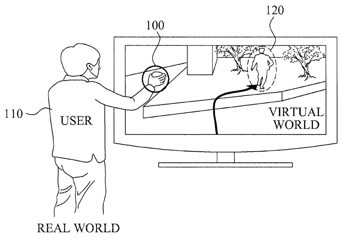
FIG. 1illustrates an operation of manipulating an object120of a virtual world, using a sensor100according to example embodiments.
Referring toFIG. 1, a user110of a real world may manipulate the object120of the virtual world using the sensor100. The user110may input his or her motion, state, intention, shape, and the like through the sensor100. The sensor100may transmit control information (CI) related to the motion, state, intention, shape, and the like of the user110, the CI included in a sensor signal, to a virtual world processing apparatus.
Depending on embodiments, the user110of the real world may include humans, animals, plants, inanimate objects such as articles, and even surrounding environment of the user110.
FIG. 2illustrates a system for manipulating an object of a virtual world using a sensor according to example embodiments.
Referring toFIG. 2, the signal that includes CI201related to the motion, state, intention, shape, and the like of a user of a real world210, the CI201input through a sensor as a real world device, may be transmitted to a virtual world processing apparatus. Depending on embodiments, the CI201related to the motion, state, intention, shape, and the like of the user may include a sensor capability, a sensor adaptation preference, and sensed information, which will be described in detail with reference toFIG. 12throughFIG. 21.
The virtual world processing apparatus may include an adaptation real world to virtual world (RV)220. The adaptation RV220may be implemented by an RV engine. The adaptation RV220may convert information of the real world210to information applicable to a virtual world240, using the CI201related to the motion, state, intention, shape, and the like of the user of the real world210, the CI201included in the sensor signal.
Depending on embodiments, the adaptation RV220may convert virtual world information (VWI)202using the CI201related to the motion, state, intention, shape, and the like of the user of the real world210.
The VWI202denotes information on the virtual world240. For example, the VWI202may include information on an object of the virtual world240or elements constituting the object.
The virtual world processing apparatus may transmit converted information203converted by the adaptation RV220to the virtual world240through adaptation real world to virtual world/virtual world to real world (RV/VR)230.
Table 1 illustrates structures shown inFIG. 2.
TABLE 1SIDCSensory input deviceVWIVirtual worldcapabilities.informationAnother expression ofsensor capabilityUSIPUser sensory inputSODCSensorypreferences.output deviceAnother expression ofcapabilitiessensor adaptation preferenceSIDCmdSensory input deviceUSOPUsercommandssensory outputAnother expression ofpreferencessensed informationVWCVirtual world capabilitiesSODCmdSensoryoutput devicecommandsVWPVirtual world preferencesSEMSensoryeffect metadataVWEMVirtual world effectSISensorymetadatainformation
FIG. 3is a view illustrating a virtual world processing apparatus for manipulating an object of a virtual world using a sensor250according to other example embodiments.
Referring toFIG. 3, the virtual world processing apparatus includes the sensor250, an adaptation RV unit255, and an adaptation VR unit260.
The sensor250may collect information on a motion, state, intention, shape, and the like of a user of a real world. The information collected by the sensor250may include sensed information.
Depending on embodiments, the sensor250may include an input unit. The input unit may be input with a sensor adaptation preference from the user of the real world.
The sensor250may encode the information collected from the real world, to first metadata. The sensor250may transmit the first metadata to the adaptation RV unit255.
The sensor250may generate the first metadata by encoding the information collected from the real world into data of a binary form. The binary-encoded first metadata may include a binary encoding syntax, a number of bits of attributes of the binary encoding syntax, and a mnemonic of the attributes of the binary encoding syntax. The sensor250may transmit the binary-encoded first metadata to the adaptation RV unit255.
Also, the sensor250may generate the first metadata by encoding the information collected from the real world into data of an extensible markup language (XML) form. The sensor250may transmit the XML-encoded first metadata to the adaptation RV unit255.
In addition, the sensor250may generate the first metadata by encoding the information collected from the real world into data of the XML form and encoding the XML-encoded data into data of the binary form. The sensor250may transmit the binary-encoded first metadata to the adaptation RV unit255.
Depending on embodiments, the sensor250may include a metadata encoder251configured to encode the collected information into metadata.
The metadata encoder251may encode the collected information to the first metadata. The sensor250may transmit the first metadata to the adaptation RV unit255. A metadata decoder261included in the adaptation RV unit255may decode the first metadata received from the sensor250.
Depending on embodiments, the metadata encoder251may include at least one of an XML encoder that encodes the collected information into XML data and a binary encoder that encodes the collected information into binary data. The metadata decoder251may include at least one of an XML decoder that decodes received XML data and a binary decoder that decodes received binary data.
Hereinafter, encoding of the information collected by the sensor250and decoding of the data received by the adaptation RV unit255according to example embodiments will be described with reference toFIGS. 4 to 6.
FIGS. 4 to 6are views illustrating a sensor271and an adaptation RV unit according to example embodiments.
Referring toFIG. 4, the sensor271may include an XML encoder272. The XML encoder272may encode information collected from the real world by the sensor271, for example sensed information, into metadata of the XML form.
The sensor271may transmit the metadata encoded by the XML encoder272to an adaptation RV unit274.
The adaptation RV unit274may include an XML decoder273. The XML decoder273may decode the metadata received from the sensor271. Referring toFIG. 5, a sensor275according to present example embodiments may include an XML encoder276and a binary encoder277. The XML encoder276may encode information collected from the real world by the sensor275, for example sensed information, into data of the XML form. The binary encoder277may encode the data encoded by the XML encoder276into data of the binary form.
In addition, the sensor275may transmit the metadata encoded by the XML encoder276and the binary encoder277to an adaptation RV280.
The adaptation RV280may include a binary decoder278and an XML decoder279. The binary decoder278may decode the metadata received from the sensor275into data of the XML form. The XML decoder279may decode again the data decoded into the XML form by the binary decoder278.
Referring toFIG. 6, a sensor281according to present example embodiments may include a binary encoder282. The binary encoder282may encode information collected from the real world by the sensor281, for example sensed information, into metadata of the binary form.
The sensor281may transmit the metadata encoded by the binary encoder282to an adaptation RV284unit.
The adaptation RV284unit may include a binary decoder283. The binary decoder283may decode the metadata received from the sensor281.
Referring back toFIG. 3, the adaptation VR unit260may encode information on the virtual world265into second metadata.
The adaptation VR unit260may generate the second metadata by encoding the information on the virtual world265into data of the binary form. The binary-encoded second metadata may include a binary encoding syntax, a number of bits of attributes of the binary encoding syntax, and a mnemonic of the attributes of the binary encoding syntax. The adaptation VR unit260may transmit the binary-encoded second metadata to the adaptation RV unit255.
Also, the adaptation VR unit260may generate the second metadata by encoding information collected from the virtual world265into the data of the XML form. The adaptation VR unit260may transmit the XML-encoded second metadata to the adaptation RV unit255.
Furthermore, the adaptation VR unit260may generate the second metadata by encoding information collected from the virtual world265into the data of the XML form and encoding the XML-encoded data to data of the binary form. The adaptation VR unit260may transmit the binary-encoded second metadata to the adaptation RV unit255.
Depending on embodiments, the adaptation VR unit260may include a metadata encoder262. The metadata encoder262may encode the information on the virtual world265into the second metadata.
Depending on embodiments, the metadata encoder262may include at least one of an XML encoder that encodes the information on the virtual world265into metadata of the XML form and a binary encoder that encodes the information on the virtual world265into metadata of the binary form.
Depending on embodiments, the metadata encoder262may include an XML encoder. The XML encoder may encode the information on the virtual world265into to data of the XML form.
In addition, the metadata encoder262may include an XML encoder and a binary encoder. The XML encoder may encode the information on the virtual world265into data of the XML form. The binary encoder may encode the data of the XML form back to data of the binary form.
Also, the metadata encoder262may include a binary encoder. The binary encoder may encode the information on the virtual world265into data of the binary form.
The adaptation RV unit255may generate information to be applied to the virtual world265, based on the first metadata transmitted from the sensor250and the second metadata transmitted from the adaptation VR unit260. Here, the adaptation RV unit255may encode the generated information into third metadata.
Depending on embodiments, the adaptation RV unit255may include a metadata decoder256, a metadata decoder258, and a metadata encoder257.
The adaptation RV unit255may generate information to be applied to the virtual world265, based on information decoded from the first metadata by the metadata decoder256and information decoded from the second metadata by the metadata decoder258. Here, the adaptation RV unit255may generate the information to be applied to the virtual world265, such that the information corresponds to virtual world object characteristics and sensed information included in the second metadata.
The metadata encoder257may encode the information, which is generated by the adaptation RV unit255and to be applied to the virtual world265, into the third metadata. In addition, the adaptation RV unit255may transmit the third metadata to the adaptation VR unit260.
The adaptation VR unit260may include the metadata decoder261. The metadata decoder261may decode the third metadata. The adaptation VR unit260may convert attributes of an object of the virtual world265based on the decoded information and, in addition, apply the converted attributes to the virtual world265.
A virtual world processing system may transmit the information on the virtual world265to an actuator of the real world so that the information is reflected to the real world. Hereinafter, example embodiments in which the information on the virtual world265is reflected to the real world will be described in detail with reference toFIGS. 7 to 9.
FIGS. 7 to 9are views illustrating an adaptation VR engine285and an actuator288according to example embodiments.
Referring toFIG. 7, the adaptation VR engine285may include an XML encoder286. The adaptation VR engine285, as an example embodiment of the adaptation RV unit255shown inFIG. 3, may transmit the information on the virtual world265to the actuator288of a real world so that the information on the virtual world265is reflected to the real world.
The adaptation VR unit260may collect information on a change in attributes of an object of the virtual world265, and transmit the collected information to the adaptation VR engine285. The adaptation VR285may include the XML encoder286. The XML encoder286may encode the information on the virtual world265into data of the XML form. In addition, the adaptation VR engine285may transmit the data encoded by the XML encoder286to the actuator288.
The actuator288may include the XML decoder287. The XML decoder287may decode the XML data received from the adaptation VR engine285.
The actuator288may operate corresponding to the information decoded by the XML decoder287.
Referring toFIG. 8, an adaptation VR engine290may include an XML encoder291and a binary encoder292.
The adaptation VR unit260may collect information on a change in attributes of the object of the virtual world265, and transmit the collected information to the adaptation VR engine290. The adaptation VR engine290may include the XML encoder291and the binary encoder292. The XML encoder291may encode the information on the virtual world265into data of the XML form. The binary encoder292may encode the data encoded by the XML encoder291back to data of the binary form. In addition, the adaptation VR engine290may transmit the data encoded by the XML encoder292to an actuator295.
The actuator295may include a binary decoder293and an XML decoder294. The binary decoder293may decode the binary data received from the adaptation VR engine290into data of the XML form. The XML decoder294may decode the data decoded into the XML form by the binary decoder293.
The actuator295may operate corresponding to the information decoded by the XML decoder294.
Referring toFIG. 9, an adaptation VR engine296may include a binary encoder297.
The adaptation VR unit260may collect information on a change in attributes of the object of the virtual world265, and transmit the collected information to the adaptation VR engine296. The adaptation VR engine296may include a binary encoder297. The binary encoder297may encode received information on the virtual world into data of the binary form. In addition, the adaptation VR engine296may transmit the data encoded by the binary encoder297to an actuator299.
The actuator299may include a binary decoder298. The binary decoder298may decode the binary data received from the adaptation VR engine296.
The actuator299may operate corresponding to the information decoded by the binary decoder298.
FIG. 10is a view illustrating a structure of a virtual world processing apparatus300according to example embodiments.
Referring toFIG. 10, the virtual world processing apparatus300includes a storage unit310and a processing unit320.
The storage unit310stores sensor capability related to a sensor.
The sensor may measure a motion, state, intention, shape, and the like of a user of a real world. The sensor may be expressed as a sensory input device. Depending on embodiments, the sensor may be classified according to sensor types including (1) acoustic, sound, and vibration, (2) automotive and transportation, (3) chemical, (4) electric current, electric potential, magnetic, and radio, (5) environment and weather, (6) flow, (7) ionizing radiation, and subatomic particles, (8) navigation instruments, (9) position, angle, displacement, distance, speed, and acceleration, (10) optical, light, and imaging, (11) pressure, force, density, and level, (12) thermal, heat, and temperature, (13) proximity and presence, and (14) sensor technology.
Table 2 illustrates examples sensor according to the sensor types. Therefore, the sensors in Table 2 are suggested only as an embodiment but not limiting.
TABLE 2sensor typelist of sensors(1) acoustic, sound,geophonevibrationhydrophonelace sensor, a guitar pickupmicrophoneseismometeraccelerometer(2) automotive,crank sensortransportationcurb feelerdefect detectormap sensorparking sensorsparktronicradar gunspeedometerspeed sensorthrottle position sensorvariable reluctance sensorwheel speed sensor(3) chemicalbreathalyzercarbon dioxide sensorcarbon monoxide detectorcatalytic bead sensorchemical field-effect transistorelectronic noseelectrolyte-insulator-semiconductor sensorhydrogen sensorinfrared point sensorion-selective electrodenondispersive infrared sensormicrowave chemistry sensornitrogen oxide sensoroptodeoxygen sensorpellistorpH glass electrodepotentiometric sensorredox electrodesmoke detectorzinc oxide nanorod sensor(4) electric current,ammeterelectric potential,current sensormagnetic, radiogalvanometerhall effect sensorhall probeleaf electroscopemagnetic anomaly detectormagnetometermetal detectormultimeterohmmetervoltmeterwatt-hour meter(5) environment,fish counterweathergas detectorhygrometerpyranometerpyrgeometerrain gaugerain sensorseismometers(6) flowair flow meterflow sensorgas metermass flow sensorwater meter(7) ionizingbubble chamberradiation, subatomiccloud chamberparticlesgeiger counterneutron detectionparticle detectorscintillation counterscintillatorwire chamber(8) navigationair speed indicatorinstrumentsaltimeterattitude indicatorfluxgate compassgyroscopeinertial reference unitmagnetic compassMHD sensorring laser gyroscopeturn coordinatorvariometervibrating structure gyroscopeyaw rate sensor(9) position, angle,accelerometerdisplacement,inclinometerdistance, speed,laser rangefinderaccelerationlinear encoderlinear variable differential transformer (LVDT)liquid capacitive inclinometersodometerpiezoelectric accelerometerposition sensorrotary encoderrotary variable differential transformerselsyntachometer(10) optical, light,charge-coupled deviceimagingcolorimeterinfra-red sensorLED as light sensornichols radiometerfiber optic sensorsphotodiodephotomultiplier tubesphototransistorphotoelectric sensorphotoionization detectorphotomultiplierphotoresistorphotoswitchphototubeproximity sensorscintillometershack-Hartmannwavefront sensor(11) pressure, force,anemometerdensity, levelbhangmeterbarographbarometerhydrometerLevel sensorLoad cellmagnetic level gaugeoscillating U-tubepressure sensorpiezoelectric sensorpressure gaugestrain gaugetorque sensorviscometer(12) thermal, heat,bolometertemperaturecalorimeterheat flux sensorinfrared thermometermicrobolometermicrowave radiometernet radiometerresistance temperature detectorresistance thermometerthermistorthermocouplethermometer(13) proximity,alarm sensorpresencebedwetting alarmmotion detectoroccupancy sensorpassive infrared sensorreed switchstud findertriangulation sensortouch switchwired glove(14) sensoractive pixel sensortechnologymachine visionbiochipbiosensorcapacitance probecatadioptric sensorcarbon paste electrodedisplacement receiverelectromechanical filmelectro-optical sensorimage sensorinductive sensorintelligent sensorlab-on-a-chipleaf sensorRADARsensor arraysensor nodesoft sensorstaring arraytransducerultrasonic sensorvideo sensor
For example, the microphone belonging to a sensor type (1) acoustic, sound, and vibration may collect voice of the user of the real world and ambient sounds of the user. The speed sensor belonging to the sensor type (2) automotive and transportation may measure speed of the user of the real world and speed of an object such as a vehicle of the real world. The oxygen sensor belonging to the sensor type (3) chemical may measure an oxygen ratio in ambient air around the user of the real world and an oxygen ratio in liquid around the user of the real world. The metal detector belonging to the sensor type (4) electric current, electric potential, magnetic, and radio may detect metallic substances present in or around the user of the real world. The rain sensor belonging to the sensor type (5) environment and weather may detect whether it is raining in the real world. The flow sensor belonging to the sensor type (6) flow may measure a ratio of a fluid flow of the real world. The scintillator belonging to the sensor type (7) ionizing radiation and subatomic particles may measure a ratio or radiation present in or around the user of the real world. The variometer belonging to the sensor type (8) navigation instruments may measure a vertical movement speed of or around the user of the real world. The odometer belonging to the sensor type (9) position, angle, displacement, distance, speed, and acceleration may measure a traveling distance of an object of the real world, such as a vehicle. The phototransistor belonging to the sensor type (10) optical, light, and imaging may measure light of the real world. The barometer belonging to the sensor type (11) pressure, force, density, and level may measure an atmospheric pressure of the real world. The bolometer belonging to the sensor type (12) thermal, heat, and temperature may measure radiation rays of the real world. The motion detector belonging to the sensor type (13) proximity and presence may measure a motion of the user of the real world. The biosensor belonging to the sensor type (14) may measure biological characteristics of the user of the real world.
FIG. 11illustrates a structure of a virtual world processing apparatus according to other example embodiments.
Referring toFIG. 11, an input device360according to the present embodiments may be input with a sensor adaptation preference361by a user of a real world. Depending on embodiments, the input device360may be modularized and inserted in a sensor370or a virtual world processing apparatus350. The sensor adaptation preference361will be described in further detail with reference toFIGS. 15 to 17.
The sensor370may transmit a sensor capability371and sensed information372to the virtual world processing apparatus350. The sensor capability371and the sensed information372will be described in further detail with reference toFIGS. 12 to 14, and18.
The virtual world processing apparatus350may include a signal processing unit351and an adaptation unit352.
The signal processing unit351may receive the sensor capability371and the sensed information372, and perform signal-processing with respect to the sensor capability371and the sensed information372. Depending on embodiments, the signal processing unit351may filter and validate the sensor capability371and the sensed information372.
The adaptation unit352may receive the sensor adaptation preference361from the input device360. In addition, based on the received sensor adaptation preference361, the adaptation unit352may perform adaptation with respect to the information signal-processed by the signal processing unit351so that the information is applied to a virtual world380. In addition, the virtual world processing apparatus350may apply the information having undergone the adaptation by the adaptation unit352to the virtual world380.
The sensor capability denotes information on capability of a sensor.
A sensor capability base type denotes a base type of the sensor capability. Depending on embodiments, the sensor capability base type may be a base abstract type of the metadata related to a sensor capability commonly applied to all types of sensors, as part of metadata types related to the sensor capability.
Hereinafter, the sensor capability and the sensor capability base type will be described in detail with reference toFIGS. 12 to 14.
FIG. 12illustrates a sensor capability base type400according to example embodiments.
Referring toFIG. 12, the sensor capability base400may include sensor capability base attributes410and any attributes420.
The sensor capability base attributes410denote a group of sensor capabilities basically included in the sensor capability base type400.
The any attributes420denote a group of additional sensor capabilities of a sensor. The any attributes420may be unique additional sensor capabilities which are applicable to an arbitrary sensor. The any attributes420may allow scalability for inclusion of attributes other than the base attributes.
FIG. 13illustrates syntax500of a sensor capability base type according to example embodiments.
Referring toFIG. 13, the syntax500of the sensor capability base type may include a diagram510, attributes520, and a source530.
The diagram510may include a diagram of the sensor capability base type.
The attributes520may include sensor capability base attributes and any attributes.
The source530may be a program representing the sensor capability base type using an extensible markup language (XML). However, the source530shown inFIG. 13is suggested by way of example but not limiting.
FIG. 14illustrates syntax600of sensor capability base attributes according to example embodiments.
Referring toFIG. 14, the syntax600of the sensor capability base attributes may include a diagram610, attributes620, and a source630.
The diagram610may include a diagram of the sensor capability base attributes.
The attributes620may include a unit601, a maximum value602, a minimum value603, an offset604, a number of levels605, a sensitivity606, a signal to noise ratio (SNR)607, and an accuracy608.
The unit601is a unit of values measured by a sensor. Depending on embodiments, for example, when the sensor is a thermometer, the unit601may be Celsius (° C.) and Fahrenheit (° F.). When the sensor is a speed sensor, the unit601may be kilometers per hour (km/h) and meters per second (m/s).
The maximum value602and the minimum value603denote a maximum value and a minimum value measurable by the sensor, respectively. Depending on embodiments, for example, when the sensor is a thermometer, the maximum value602may be 50° C. and the minimum value603may be 0° C. Even in the same type of sensor, for example, the thermometer, the maximum value602and the minimum value603may be varied according to use and function of the sensor.
The offset604denotes an offset value added to a value measured by the sensor to obtain an absolute value. Depending on embodiments, for example, presuming that the sensor is a speed sensor and a user or an object of a real world stays still, when a value other than zero is measured as speed, the sensor may determine the offset604to a value making the speed zero. For example, when −1 km/h is measured as speed of a vehicle of the real world, the offset604may be 11 cm/h.
The number of levels605denotes a number of values measurable by the sensor. Depending on embodiments, for example, presuming that the sensor is a thermometer and the maximum value and the minimum value are 50° C. and 0° C., respectively, when the number of levels605is 5, the sensor may measure five values, that is, 10° C., 20° C., 30° C., 40° C., and 50° C. Even when temperature of the real world is 27° C., not only when 20° C., the temperature may be measured as 20° C. through round-down. Alternative, in this case, the temperature may be measured as 30° C. through roundup.
The sensitivity606denotes a minimum input value required for the sensor to measure an output value. Depending on embodiments, for example, when the sensor is a thermometer and the sensitivity606is 1° C., the sensor may not measure a temperature change less than 1° C. but measure only the temperature change of at least 1° C.
The SNR607denotes a relative degree of a signal measured by the sensor with respect to a noise. Depending on embodiments, presuming that the sensor is a microphone to measure and a vocal sound of the user of the real world is to be measured, when an ambient noise is large, the SNR607of the sensor may be relatively small.
The accuracy608denotes an error of the sensor. Depending on embodiments, when the sensor is a microphone, the accuracy608may be a measurement error caused by variation of a propagation speed of a sound according to temperature, humidity, and the like. Alternatively, the accuracy608may be determined through a statistical error of the values already measured by the sensor.
Depending on embodiments, the attributes620may further include a position. The position denotes a position of the sensor. When the sensor is a thermometer, the position of the sensor may be an armpit of the user of the real world. The position may include longitude and latitude, and height and direction from a ground surface.
The unit601, the maximum value602, the minimum value603, the offset604, the number of levels605, the sensitivity606, the SNR607, the accuracy608, and the position, as the sensor capability base attributes, may be rearranged as shown in Table 3.
TABLE 3NameDefinitionUnit 601the unit of valuemaxValuethe maximum value that the input device (sensor) can602provide. The terms will be different according to theindividual device type.minValuethe minimum value that the input device (sensor) can603provide. The terms will be different according to theindividual device type.Offset 604the number of value locations added to a base valuein order to get to a specific absolute value.numOflevelsthe number of value levels that the device can605provide in between maximum and minimum value.Sensitivitythe minimum magnitude of input signal required to606produce a specified output signal.SNR 607the ratio of a signal power to the noise powercorrupting the signalAccuracythe degree of closeness of a measured quantity to608its actual valuePositionthe position of the device from the user'sperspective according to the x-, y-, and z-axis
The source630may be a program representing the sensor capability base attributes using the XML.
A reference numeral631of the source630defines the maximum value602using the XML. According to the reference numeral631, the maximum value602has “float” type data and is optionally used.
A reference numeral632of the source630defines the minimum value603using the XML. According to the reference numeral632, the minimum value603has “float” type data and is optionally used.
A reference numeral633of the source630defines the number of levels605using the XML. According to the reference numeral633, the number of levels605has “on NegativeInteger” type data and is optionally used.
However, the source630shown inFIG. 14is not limiting but only example embodiments.
Referring toFIG. 10again, the processing unit320may determine a first value received from the sensor based on the sensor capability, and transmit a second value corresponding to the first value to the virtual world.
Depending on embodiments, the processing unit320may transmit the second value to the virtual world when the first value received from the sensor is less than or equal to a maximum value measurable by the sensor and greater than or equal to a minimum value measurable by the sensor.
Depending on embodiments, when the first value received from the sensor is greater than the maximum value, the processing unit320may consider the first value as the maximum value and transmit the second value to the virtual world. Also, when the first value is less than the minimum value, the processing unit320may consider the first value as the minimum value and transmit the second value to the virtual world.
The virtual world processing apparatus300may further include a second storage unit (not shown) configured to store a sensor adaptation preference for manipulation of the first value received from the sensor. The processing unit320may generate a third value from the first value based on the sensor capability, and generate the second value from the third value based on the sensor adaptation preference.
Depending on embodiments, information on the motion, state, intention, shape, and the like of the user of the real world, which are measured through the sensor, may be directly reflected to the virtual world.
Hereinafter, the sensor capability will be described in relation to specific embodiments of the sensor. Although not limited to those embodiments, the sensor may include a position sensor, an orientation sensor, an acceleration sensor, a light sensor, a sound sensor, a temperature sensor, a humidity sensor, a distance sensor, a motion sensor, an intelligent camera sensor, an ambient noise sensor, an atmospheric sensor, a velocity sensor, an angular velocity sensor, an angular acceleration sensor, a force sensor, a torque sensor, and a pressure sensor.
Source 1 denotes a sensor capability related to the position sensor using the XML. However, a program source shown in Source 1 is only an example embodiment but does not limit the present invention.
[Source 1]
A position sensor capability type is a tool for describing the sensor capability related to the position sensor.
The position sensor capability type may include sensor capability base attributes related to the position sensor.
The sensor capability base attributes related to the position sensor may include a range, a range type, an x maximum value, an x minimum value, a y maximum value, a y minimum value, a z maximum value, and a z minimum value.
The range denotes a range measurable by the position sensor. For example, the measurable range of the position sensor may be expressed using the range type and a global coordinate system.
An origin of the global coordinate may be located at a top left corner. A right handed coordinate system may be applied as the global coordinate. In the global coordinate, a positive direction of an x-axis may be a direction to a top right corner of a screen, a positive direction of a y-axis may be a gravity direction, that is, a bottomward direction of the screen, and a positive direction of a z-axis may be a direction opposite to the user, that is, a direction into the screen.
The range type denotes a range of the global coordinate system according to the x-axis, the y-axis, and the z-axis.
The x maximum value denotes a maximum value on the x-axis, measurable by the position sensor using a unit of a position coordinate, for example, meter.
The x minimum value denotes a minimum value on the x-axis, measurable by the position sensor using a unit of a position coordinate, for example, meter.
The y maximum value denotes a maximum value on the y-axis, measurable by the position sensor using a unit of a position coordinate, for example, meter.
The y minimum value denotes a minimum value on the y-axis, measurable by the position sensor using a unit of a position coordinate, for example, meter.
The z maximum value denotes a maximum value on the z-axis, measurable by the position sensor using a unit of a position coordinate, for example, meter.
The z minimum value denotes a minimum value on the z-axis, measurable by the position sensor using a unit of a position coordinate, for example, meter.
Source 2 denotes a sensor capability related to an orientation sensor using the XML. However, a program source shown in Source 2 is only an example embodiment but does not limit the present invention.
[Source 2]
An orientation sensor capability type is a tool for describing the sensor capability related to the orientation sensor.
The orientation sensor capability type may include sensor capability base attributes related to the orientation sensor.
The sensor capability base attributes related to the orientation sensor may include an orientation range, an orientation range type, an x maximum value, an x minimum value, a y maximum value, a y minimum value, a z maximum value, and a z minimum value.
The range denotes a range measurable by the orientation sensor. For example, the measurable range of the orientation sensor may be expressed using the orientation range type and the global coordinate system.
The orientation range type denotes an orientation range of the global coordinate system according to the x-axis, the y-axis, and the z-axis.
The x maximum value denotes a maximum value on the x-axis, measurable by the orientation sensor using a unit of an orientation coordinate, for example, radian.
The x minimum value denotes a minimum value on the x-axis, measurable by the orientation sensor using a unit of an orientation coordinate, for example, radian.
The y maximum value denotes a maximum value on the y-axis, measurable by the orientation sensor using a unit of an orientation coordinate, for example, radian.
The y minimum value denotes a minimum value on the y-axis, measurable by the orientation sensor using a unit of an orientation coordinate, for example, radian.
The z maximum value denotes a maximum value on the z-axis, measurable by the orientation sensor using a unit of an orientation coordinate, for example, radian.
The z minimum value denotes a minimum value on the z-axis, measurable by the orientation sensor using a unit of an orientation coordinate, for example, radian.
Source 3 denotes a sensor capability related to an acceleration sensor using the XML. However, a program source shown in Source 3 is only an example embodiment but does not limit the present invention.
[Source 3]
An acceleration sensor capability type is a tool for describing the sensor capability related to the acceleration sensor.
The acceleration sensor capability type may include sensor capability base to attributes related to the acceleration sensor.
The sensor capability base attributes related to the acceleration sensor may include a maximum value and a minimum value.
The maximum value denotes a maximum value measurable by the acceleration sensor using a unit of acceleration, for example, m/s2.
The minimum value denotes a minimum value measurable by the acceleration sensor using a unit of acceleration, for example, m/s2.
Source 4 denotes a sensor capability related to a light sensor using the XML. However, a program source shown in Source 4 is only an example embodiment but does not limit the present invention.
[Source 4]
A light sensor capability type is a tool for describing the sensor capability related to the light sensor.
The light sensor capability type may include sensor capability base attributes related to the light sensor.
The sensor capability base attributes related to the light sensor may include a maximum value, a minimum value, a color, and a location.
The maximum value denotes a maximum value measurable by the light sensor using a unit of light intensity, for example, LUX.
The minimum value denotes a minimum value measurable by the light sensor using a unit of light intensity, for example, LUX.
The color denotes a color that may be provided by the light sensor. For example, the color may be an RGB color value.
The location denotes a location of the light sensor. For example, the location of the light sensor may be expressed using the global coordinate according to the x-axis, the y-axis, and the z-axis.
Source 5 denotes a sensor capability related to a sound sensor using the XML. However, a program source shown in Source 5 is only an example embodiment but does not limit the present invention.
[Source 5]
A sound sensor capability type is a tool for describing the sensor capability related to the sound sensor.
The sound sensor capability type may include sensor capability base attributes related to the sound sensor.
The sensor capability base attributes related to the sound sensor may include a maximum value and a minimum value.
The maximum value denotes a maximum value measurable by the sound sensor using a unit of sound intensity, for example, decibel (dB).
The minimum value denotes a minimum value measurable by the sound sensor using a unit of sound intensity, for example, dB.
Source 6 denotes a sensor capability related to a temperature sensor using the XML. However, a program source shown in Source 6 is only an example embodiment but does not limit the present invention.
[Source 6]
A temperature sensor capability type is a tool for describing the sensor capability related to the temperature sensor.
The temperature sensor capability type may include sensor capability base attributes related to the temperature sensor.
The sensor capability base attributes related to the temperature sensor may include a maximum value, a minimum value, and a location.
The maximum value denotes a maximum value measurable by the temperature sensor using a unit of temperature, for example, ° C. and ° F.
The minimum value denotes a minimum value measurable by the temperature sensor using a unit of temperature, for example, ° C. and ° F.
The location denotes a location of the temperature sensor. For example, the location of the temperature sensor may be expressed using the global coordinate according to the x-axis, the y-axis, and the z-axis.
Source 7 denotes a sensor capability related to a humidity sensor using the XML. However, a program source shown in Source 7 is only an example embodiment but does not limit the present invention.
[Source 7]
A humidity sensor capability type is a tool for describing the sensor capability related to the humidity sensor.
The humidity sensor capability type may include sensor capability base attributes related to the humidity sensor.
The humidity capability base attributes related to the humidity sensor may include a maximum value, a minimum value, and a location.
The maximum value denotes a maximum value measurable by the humidity sensor using a unit of humidity, for example, percent (%).
The minimum value denotes a minimum value measurable by the humidity sensor using a unit of humidity, for example, %.
The location denotes a location of the humidity sensor. For example, the location of the humidity sensor may be expressed using the global coordinate according to the x-axis, the y-axis, and the z-axis.
Source 8 denotes a sensor capability related to a distance sensor using the XML. However, a program source shown in Source 8 is only an example embodiment but does not limit the present invention.
[Source 8]
A distance sensor capability type is a tool for describing the sensor capability related to the distance sensor.
The distance sensor capability type may include sensor capability base attributes related to the distance sensor.
The sensor capability base attributes related to the distance sensor may include a maximum value, a minimum value, and a location.
The maximum value denotes a maximum value measurable by the distance sensor using a unit of length, for example, meter.
The minimum value denotes a minimum value measurable by the distance sensor using a unit of length, for example, meter.
The location denotes a location of the distance sensor. For example, the location of the distance sensor may be expressed using the global coordinate according to the x-axis, the y-axis, and the z-axis.
Source 9 denotes a sensor capability related to a motion sensor using the XML. However, a program source shown in Source 9 is only an example embodiment but does not limit the present invention.
[Source 9]
A motion sensor capability type is a tool for describing the sensor capability related to the motion sensor.
The motion sensor may be an integrated sensor of a plurality of sensors. For example, the motion sensor may integrally include a position sensor, a velocity sensor, an acceleration sensor, an orientation sensor, an angular velocity sensor, and an angular acceleration sensor.
The motion sensor capability type may include sensor capability base attributes related to the motion sensor.
The sensor capability base attributes related to the motion sensor may include a position capability, a velocity capability, an acceleration capability, an orientation capability, an angular velocity capability, and an angular acceleration capability.
The position capability denotes capability with respect to the position.
The velocity capability denotes capability with respect to the velocity.
The acceleration capability denotes capability with respect to the acceleration.
The orientation capability denotes capability with respect to the orientation.
The angular velocity capability denotes capability with respect to the angular velocity.
The angular acceleration capability denotes capability with respect to the angular acceleration.
Source 10 denotes a sensor capability related to an intelligent camera sensor using the XML. However, a program source shown in Source 10 is only an example embodiment but does not limit the present invention.
[Source 10]
An intelligent camera sensor capability type is a tool for describing the sensor capability related to the intelligent camera sensor.
The intelligent camera sensor capability type may include sensor capability base attributes related to the intelligent camera sensor.
The sensor capability base attributes related to the intelligent camera sensor may include a feature tracking status, an expression tracking status, a body movement tracking status, a maximum body feature point, a maximum face feature point, a tracked feature, tracked facial feature points, tracked body feature points, a feature type, a facial feature mask, and a body feature mask.
The feature tracking status denotes information on whether an intelligent camera is capable of tracking features.
The expression tracking status denotes information on whether the intelligent camera is capable of extracting animation related to a facial expression.
The body movement tracking status denotes information on whether the intelligent camera is capable of extracting animation related to a body.
The maximum body feature point denotes a maximum value of a body feature that can be tracked by the intelligent camera sensor.
The maximum face feature point denotes a maximum value of a face feature that can be tracked by the intelligent camera sensor.
The tracked feature denotes information on whether tracking of the body feature and the face feature is possible.
The tracked facial feature points denote information on whether the respective face features are activated or based on the facial feature mask.
The tracked body feature points denote information on whether the respective body features are activated or based on the body feature mask.
The feature type denotes a list of feature types. For example, the feature type may include 1. Face, 2. Body, and 3. Face and body.
The facial feature mask denotes a list of facial features.
The body feature mask denotes a list of body features.
Source 11 denotes a sensor capability related to an ambient noise sensor using the XML. However, a program source shown in Source 11 is only an example embodiment but does not limit the present invention.
[Source 11]
An ambient noise sensor capability type is a tool for describing the sensor capability related to the ambient noise sensor.
The ambient noise sensor capability type may include sensor capability base attributes related to the ambient noise sensor.
The sensor capability base attributes related to the ambient noise sensor may include a maximum value, a minimum value, and a location.
The maximum value denotes a maximum value measurable by the ambient noise sensor. For example, a unit for the ambient noise sensor may be dB.
The minimum value denotes a minimum value measurable by the ambient noise sensor. For example, a unit for the ambient noise sensor may be dB.
The location denotes a location of the ambient noise sensor. For example, the location of the ambient noise sensor may be expressed using the global coordinate according to the x-axis, the y-axis, and the z-axis.
Source 12 denotes a sensor capability related to an atmospheric pressure sensor using the XML. However, a program source shown in Source 12 is only an example embodiment but does not limit the present invention.
[Source 12]
An atmospheric pressure sensor capability type is a tool for describing the sensor capability related to the atmospheric pressure sensor.
The atmospheric pressure sensor capability type may include sensor capability base attributes related to the atmospheric pressure sensor.
The atmospheric pressure capability base attributes related to the atmospheric pressure sensor may include a maximum value, a minimum value, and a location.
The maximum value denotes a maximum value measurable by the atmospheric pressure sensor using a unit of atmospheric pressure, for example, hectopascal (hPa).
The minimum value denotes a minimum value measurable by the atmospheric pressure sensor using a unit of atmospheric pressure, for example, hPa.
The location denotes a location of the atmospheric pressure sensor. For example, the location of the atmospheric pressure sensor may be expressed using the global coordinate according to the x-axis, the y-axis, and the z-axis.
Source 13 denotes a sensor capability related to a velocity sensor using the XML. However, a program source shown in Source 13 is only an example embodiment but does not limit the present invention.
[Source 13]
A velocity sensor capability type is a tool for describing the sensor capability related to the velocity sensor.
The velocity sensor capability type may include sensor capability base attributes related to the velocity sensor.
The velocity capability base attributes related to the velocity sensor may include a maximum value and a minimum value.
The maximum value denotes a maximum value measurable by the velocity sensor using a unit of velocity, for example, m/s.
The minimum value denotes a minimum value measurable by the velocity sensor using a unit of velocity, for example, m/s.
Source 14 denotes a sensor capability related to an angular velocity sensor using the XML. However, a program source shown in Source 14 is only an example embodiment but does not limit the present invention.
[Source 14]
An angular velocity sensor capability type is a tool for describing the sensor capability related to the angular velocity sensor.
The angular velocity sensor capability type may include sensor capability base attributes related to the angular velocity sensor.
The angular velocity capability base attributes related to the angular velocity sensor may include a maximum value and a minimum value.
The maximum value denotes a maximum value measurable by the angular velocity sensor using a unit of angular velocity, for example, radian/s.
The minimum value denotes a minimum value measurable by the angular velocity sensor using a unit of angular velocity, for example, radian/s.
Source 15 denotes a sensor capability related to an angular acceleration sensor using the XML. However, a program source shown in Source 15 is only an example embodiment but does not limit the present invention.
[Source 15]
An angular acceleration sensor capability type is a tool for describing the sensor capability related to the angular acceleration sensor.
The angular acceleration sensor capability type may include sensor capability base attributes related to the angular acceleration sensor.
The angular acceleration capability base attributes related to the angular acceleration sensor may include a maximum value and a minimum value.
The maximum value denotes a maximum value measurable by the angular acceleration sensor using a unit of angular acceleration, for example, radian/s2.
The minimum value denotes a minimum value measurable by the angular acceleration sensor using a unit of angular acceleration, for example, radian/s2.
Source 16 denotes a sensor capability related to a force sensor using the XML. However, a program source shown in Source 16 is only an example embodiment but does not limit the present invention.
[Source 16]
A force sensor capability type is a tool for describing the sensor capability related to the force sensor.
The force sensor capability type may include sensor capability base attributes related to the force sensor.
The force capability base attributes related to the force sensor may include a maximum value and a minimum value.
The maximum value denotes a maximum value measurable by the force sensor using a unit of force, for example, Newton (N).
The minimum value denotes a minimum value measurable by the force sensor using a unit of force, for example, N.
Source 17 denotes a sensor capability related to a torque sensor using the XML. However, a program source shown in Source 17 is only an example embodiment but does not limit the present invention.
[Source 17]
A torque sensor capability type is a tool for describing the sensor capability related to the torque sensor.
The torque sensor capability type may include sensor capability base attributes related to the torque sensor.
The torque capability base attributes related to the torque sensor may include a maximum value, a minimum value, and a location.
The maximum value denotes a maximum value measurable by the torque sensor using a unit of torque, for example, Newton millimeter (N-mm).
The minimum value denotes a minimum value measurable by the torque sensor using a unit of torque, for example, N-mm.
Source 18 denotes a sensor capability related to a pressure sensor using the XML. However, a program source shown in Source 18 is only an example embodiment but does not limit the present invention.
[Source 18]
A pressure sensor capability type is a tool for describing the sensor capability related to the pressure sensor.
The pressure sensor capability type may include sensor capability base attributes related to the pressure sensor.
The pressure capability base attributes related to the pressure sensor may include a maximum value, a minimum value, and a location.
The maximum value denotes a maximum value measurable by the pressure sensor using a unit of pressure, for example, m/s.
The minimum value denotes a minimum value measurable by the pressure sensor using a unit of pressure, for example, m/s.
Hereinafter, the sensor adaptation preference will be described in detail.
The sensor adaptation preference denotes information for manipulating a value received from a sensor.
A sensor adaptation preference base type denotes a base type of manipulation information of the user. Depending on embodiments, the sensor adaptation preference base type may be a base abstract type of the metadata related to a sensor adaptation preference commonly applied to all types of sensors, as part of metadata types related to the sensor adaptation preference.
Hereinafter, the sensor adaptation preference and the sensor adaptation preference base type will be described in detail with reference toFIGS. 15 through 17.
FIG. 15illustrates a sensor adaptation preference base type700according to example embodiments.
Referring toFIG. 15, the sensor adaptation preference base type700may include sensor adaptation preference base attributes710and any attributes720.
The sensor adaptation preference base attributes710denote a group of sensor adaptation preferences basically included in the sensor adaptation preference base type700.
The any attributes720denote a group of additional sensor adaptation preferences. The any attributes720may be unique additional sensor capabilities which are applicable to an arbitrary sensor. The any attributes420may allow scalability for inclusion of attributes other than the base attributes.
FIG. 16illustrates syntax800of a sensor adaptation preference base type according to example embodiments.
Referring toFIG. 16, the syntax of the sensor adaptation preference base type may include a diagram810, attributes820, and a source830.
The diagram810may include a diagram of the sensor adaptation preference base type.
The attributes820may include sensor adaptation preference base attributes and any attributes.
The source830may be a program representing the sensor adaptation preference base type using an XML. However, the source830shown inFIG. 16is suggested by way of example but not limiting.
FIG. 17illustrates syntax900of sensor adaptation preference base attributes according to example embodiments.
Referring toFIG. 17, the syntax900of the sensor adaptation preference base attributes may include a diagram910, attributes920, and a source930.
The diagram910may include a diagram of the sensor adaptation preference base attributes.
The attributes920may include a sensor reference identifier (ID)901, a sensor adaptation mode902, an activation state903, a unit904, a maximum value905, a minimum value906, and a number of levels907.
The sensor reference ID901denotes information referencing an ID of an individual sensor that generates specific sensed information.
The sensor adaptation mode902denotes user preference information related to a method of adapting a sensor. Depending on embodiments, the sensor adaptation mode902may be a sensor adaptation preference related to an adaptation method that refines information on a motion, state, intention, shape, and the like of a user of a real world, measured through the sensor, and reflects the information to a virtual world. For example, a ‘strict’ value may denote a user preference that directly applies sensed information of the real world to the virtual world. A ‘scalable’ value may denote a user preference that varies the sensed information of the real world according to the user preference and applies the sensed information to the virtual world.
The activation state information903denotes information on whether to activate the sensor in the virtual world. Depending on embodiments, the activation state information903may be a sensor adaptation preference that determines whether the sensor is in operation.
The unit904denotes a unit of a value used in the virtual world. For example, the unit904may be a pixel. Also, the unit904may be a unit of a value corresponding to the value received from the sensor.
The maximum value905and the minimum value906denote a maximum value and a minimum value used in the virtual world, respectively. Depending on embodiments, the maximum value905and the minimum value906may be the unit of the value corresponding to the value received from the sensor.
The number of levels907denotes a number of levels used in the virtual world. Depending on embodiments, the number of levels907may be a value for dividing levels between the maximum value and the minimum used in the virtual world.
The sensor reference ID901, the adaptation mode902, the activation state903, the unit904, the maximum value905, the minimum value906, and the number of levels907, as the sensor adaptation preference base attributes, may be rearranged as shown in Table 4.
TABLE 4NameDefinitionSensorIdRefRefers the Id of an individual sensor that has901generated the specific sensed informationSensorthe user's preference on the adaptation methodadaptation modefor the virtual world effect902Activate 903whether the effect shall be activated. a value oftrue means the effect shall be activated and falsemeans the effect shall be deactivatedUnit 904the unit of valuemaxValue 905the maximum desirable value of the effect inpercentage according to the max scale defined withinthe semantics definition of the individual effectsminValue 906the minimum desirable value of the effect inpercentage according to the min scale defined withinthe semantics definition of the individual effectsnumOflevelsthe number of value levels that the device can907provide in between maximum and minimum value
The source930may be a program representing the sensor adaptation preference base attributes using the XML.
A reference numeral931defines the activation state903using the XML. According to the reference numeral931, the activation state903has “boolean” type data and is optionally used.
A reference numeral932defines the maximum value905using the XML. According to the reference numeral932, the maximum value905has “float” type data and is optionally used.
A reference number933defines minimum value906using the XML. According to the reference numeral933, the minimum value906has “float” type data and is optionally used.
A reference numeral934defines the number of levels907using the XML. According to the reference numeral934, the number of levels907has “on NegativeInteger” type data and is optionally used. However, the source930illustrated inFIG. 17is not limiting but only example embodiments.
Hereinafter, the sensor adaptation preference will be described in relation to specific embodiments of the sensor.
Source 19 denotes a sensor adaptation preference related to a position sensor using the XML. However, a program source shown in Source 19 is only an example embodiment but does not limit the present invention.
[Source 19]
A position sensor type is a tool for describing the sensor adaptation preference related to the position sensor.
A position sensor capability type may include sensor adaptation preference base attributes related to the position sensor.
The sensor adaptation preference base attributes related to the position sensor may include a range and a number of levels.
The range denotes a range of a user preference with respect to position information measured by the position sensor.
The number of levels denotes a number of levels of the user preference with respect to the position information measured by the position sensor.
Source 20 denotes a sensor adaptation preference related to an orientation sensor using the XML. However, a program source shown in Source 20 is only an example embodiment but does not limit the present invention.
[Source 20]
An orientation sensor type is a tool for describing the sensor adaptation preference related to the orientation sensor.
An orientation sensor capability type may include sensor adaptation preference base attributes related to the orientation sensor.
The sensor adaptation preference base attributes related to the orientation sensor may include an orientation range and a number of levels.
The orientation range denotes a range of a user preference with respect to orientation information measured by the orientation sensor.
The number of levels denotes a number of levels of the user preference with respect to the orientation information measured by the orientation sensor.
Source 21 denotes a sensor adaptation preference related to an acceleration sensor using the XML. However, a program source shown in Source 21 is only an example embodiment but does not limit the present invention.
[Source 21]
An acceleration sensor type is a tool for describing the sensor adaptation preference related to the acceleration sensor.
An acceleration sensor capability type may include sensor adaptation preference base attributes related to the acceleration sensor.
The sensor adaptation preference base attributes related to the acceleration sensor may include a maximum value, a minimum value, and a number of levels.
The maximum value denotes a maximum value of a user preference related to acceleration information measured by the acceleration sensor.
The minimum value denotes a minimum value of the user preference related to the acceleration information measured by the acceleration sensor.
The number of levels denotes a number of levels of the user preference with respect to the acceleration information measured by the acceleration sensor.
Source 22 denotes a sensor adaptation preference related to a light sensor using the XML. However, a program source shown in Source 22 is only an example embodiment but does not limit the present invention.
[Source 22]
A light sensor type is a tool for describing the sensor adaptation preference related to the light sensor.
A light sensor capability type may include sensor adaptation preference base attributes related to the light sensor.
The sensor adaptation preference base attributes related to the light sensor may include a maximum value, a minimum value, a number of levels, and an unfavorable color.
The maximum value denotes a maximum value of a user preference related to a value measured by the light sensor.
The minimum value denotes a minimum value of the user preference related to a value measured by the light sensor.
The number of levels denotes a number of levels of the user preference with respect to a value measured by the light sensor.
The unfavorable color denotes a list of unfavorable colors of the user, as RGB color values or a classification reference.
Source 23 denotes a sensor adaptation preference related to a sound sensor using the XML. However, a program source shown in Source 23 is only an example embodiment but does not limit the present invention.
[Source 23]
A sound sensor type is a tool for describing the sensor adaptation preference related to the sound sensor.
A sound sensor capability type may include sensor adaptation preference base attributes related to the sound sensor.
The sensor adaptation preference base attributes related to the sound sensor may include a maximum value and a minimum value.
The maximum value denotes a maximum value allowed by the user as a measured value of the sound sensor.
The minimum value denotes a minimum value allowed by the user as a measured value of the sound sensor.
Source 24 denotes a sensor adaptation preference related to a temperature sensor using the XML. However, a program source shown in Source 24 is only an example embodiment but does not limit the present invention.
[Source 24]
A temperature sensor type is a tool for describing the sensor adaptation preference related to the temperature sensor.
A temperature sensor capability type may include sensor adaptation preference base attributes related to the temperature sensor.
The sensor adaptation preference base attributes related to the temperature sensor may include a maximum value, a minimum value, and a number of levels.
The maximum value denotes a maximum value of a user preference related to temperature information measured by the temperature sensor.
The minimum value denotes a minimum value of the user preference related to the temperature information measured by the temperature sensor.
The number of levels denotes a number of levels of the user preference with respect to the temperature information measured by the temperature sensor.
Source 25 denotes a sensor adaptation preference related to a humidity sensor using the XML. However, a program source shown in Source 25 is only an example embodiment but does not limit the present invention.
[Source 25]
A humidity sensor type is a tool for describing the sensor adaptation preference related to the humidity sensor.
A humidity sensor capability type may include sensor adaptation preference base attributes related to the humidity sensor.
The sensor adaptation preference base attributes related to the humidity sensor may include a maximum value, a minimum value, and a number of levels.
The maximum value denotes a maximum value of a user preference related to humidity information measured by the humidity sensor.
The minimum value denotes a minimum value of the user preference related to the humidity information measured by the humidity sensor.
The number of levels denotes a number of levels of the user preference with respect to the humidity information measured by the humidity sensor.
Source 26 denotes a sensor adaptation preference related to a distance sensor using the XML. However, a program source shown in Source 26 is only an example embodiment but does not limit the present invention.
[Source 26]
A distance sensor type is a tool for describing the sensor adaptation preference related to the distance sensor.
A distance sensor capability type may include sensor adaptation preference base attributes related to the distance sensor.
The sensor adaptation preference base attributes related to the distance sensor may include a maximum value, a minimum value, and a number of levels.
The maximum value denotes a maximum value of a user preference related to length information measured by the distance sensor.
The minimum value denotes a minimum value of the user preference related to the length information measured by the distance sensor.
The number of levels denotes a number of levels of the user preference with respect to the length information measured by the distance sensor.
Source 27 denotes a sensor adaptation preference related to a motion sensor using the XML. However, a program source shown in Source 27 is only an example embodiment but does not limit the present invention.
[Source 27]
A motion sensor capability type is a tool for describing the sensor adaptation preference related to the motion sensor.
The motion sensor capability type may include sensor adaptation preference base attributes related to the motion sensor.
The sensor adaptation preference base attributes related to the motion sensor may include a position preference, a velocity preference, an acceleration preference, an orientation preference, an angular velocity preference, and an angular acceleration preference.
The position preference denotes a user preference with respect to the position.
The velocity preference denotes a user preference with respect to the velocity.
The acceleration preference denotes a user preference with respect to the acceleration.
The orientation preference denotes a user preference with respect to the orientation.
The angular velocity preference denotes a user preference with respect to the angular velocity.
The angular acceleration preference denotes a user preference with respect to the angular acceleration.
Source 28 denotes a sensor adaptation preference related to an intelligent camera sensor using the XML. However, a program source shown in Source 28 is only an example embodiment but does not limit the present invention.
[Source 28]
An intelligent camera sensor capability type is a tool for describing the sensor adaptation preference related to the intelligent camera sensor.
The intelligent camera sensor capability type may include sensor adaptation preference base attributes related to the intelligent camera sensor.
The sensor adaptation preference base attributes related to the intelligent camera sensor may include a face feature tracking on, a body feature tracking on, a facial expression tracking on, a gesture tracking on, a face tracking map, and a body tracking map.
The face feature tracking on denotes information on whether to activate a face feature tracking mode in which an intelligent camera sensor tracks features on a face of the user.
The body feature tracking on denotes information on whether to activate a body feature tracking mode in which the intelligent camera sensor tracks features on a body of the user.
The facial expression tracking on denotes information on user preference with respect to tracking of a facial expression of the user by the intelligent camera sensor.
The gesture tracking on denotes information on user preference with respect to tracking of a gesture of the user by the intelligent camera sensor.
The face tracking map provides a Boolean map related to a face tracking map type. The Boolean map provides face portions that the user wants to track. Depending on embodiments, the Boolean map according to the face tracking map type may provide eyes, a mouth, a noise, and ears as the face portions.
The body tracking map provides a Boolean map related to a body tracking map type. The Boolean map provides body portions that the user wants to track. Depending on embodiments, the Boolean map according to the body tracking map type may provide a head, arms, hands, legs, feet, and a middle body as the body portions.
Source 29 denotes a sensor adaptation preference related to an ambient noise sensor using the XML. However, a program source shown in Source 29 is only an example embodiment but does not limit the present invention.
[Source 29]
An ambient noise sensor type is a tool for describing the sensor adaptation preference related to the ambient noise sensor.
An ambient noise sensor capability type may include sensor adaptation preference base attributes related to the ambient noise sensor.
The sensor adaptation preference base attributes related to the ambient noise sensor may include a maximum value, a minimum value, and a number of levels.
The maximum value denotes a maximum value of a user preference with respect to ambient noise information measured by the ambient noise sensor.
The minimum value denotes a minimum value of the user preference with respect to the ambient noise information measured by the ambient noise sensor.
The number of levels denotes a number of levels of the user preference with respect to the ambient noise information measured by the ambient noise sensor.
Source 30 denotes a sensor adaptation preference related to an atmospheric pressure sensor using the XML. However, a program source shown in Source 30 is only an example embodiment but does not limit the present invention.
[Source 30]
An atmospheric pressure sensor type is a tool for describing the sensor adaptation preference related to the atmospheric pressure sensor.
An atmospheric pressure sensor capability type may include sensor adaptation preference base attributes related to the atmospheric pressure sensor.
The sensor adaptation preference base attributes related to the atmospheric pressure sensor may include a maximum value, a minimum value, and a number of levels.
The maximum value denotes a maximum value of a user preference with respect to atmospheric pressure information measured by the atmospheric pressure sensor.
The minimum value denotes a minimum value of the user preference with respect to the atmospheric pressure information measured by the atmospheric pressure sensor.
The number of levels denotes a number of levels of the user preference with respect to the atmospheric pressure information measured by the atmospheric pressure sensor.
Source 31 denotes a sensor adaptation preference related to a velocity sensor using the XML. However, a program source shown in Source 31 is only an example embodiment but does not limit the present invention.
[Source 31]
A velocity sensor type is a tool for describing the sensor adaptation preference related to the velocity sensor.
A velocity sensor capability type may include sensor adaptation preference base attributes related to the velocity sensor.
The sensor adaptation preference base attributes related to the velocity sensor may include a maximum value, a minimum value, and a number of levels.
The maximum value denotes a maximum value of a user preference with respect to velocity information measured by the velocity sensor.
The minimum value denotes a minimum value of the user preference with respect to the velocity information measured by the velocity sensor.
The number of levels denotes a number of levels of the user preference with respect to the velocity information measured by the velocity sensor.
Source 32 denotes a sensor adaptation preference related to an angular velocity sensor using the XML. However, a program source shown in Source 32 is only an example embodiment but does not limit the present invention.
[Source 32]
An angular velocity sensor type is a tool for describing the sensor adaptation preference related to the angular velocity sensor.
An angular velocity sensor capability type may include sensor adaptation preference base attributes related to the angular velocity sensor.
The sensor adaptation preference base attributes related to the angular velocity sensor may include a maximum value, a minimum value, and a number of levels.
The maximum value denotes a maximum value of a user preference with respect to angular velocity information measured by the angular velocity sensor.
The minimum value denotes a minimum value of the user preference with respect to the angular velocity information measured by the angular velocity sensor.
The number of levels denotes a number of levels of the user preference with respect to the angular velocity information measured by the angular velocity sensor.
Source 33 denotes a sensor adaptation preference related to an angular acceleration sensor using the XML. However, a program source shown in Source 33 is only an example embodiment but does not limit the present invention.
[Source 33]
An angular acceleration sensor type is a tool for describing the sensor adaptation preference related to the angular acceleration sensor.
An angular acceleration sensor capability type may include sensor adaptation preference base attributes related to the angular acceleration sensor.
The sensor adaptation preference base attributes related to the angular acceleration sensor may include a maximum value, a minimum value, and a number of levels.
The maximum value denotes a maximum value of a user preference with respect to angular acceleration information measured by the angular acceleration sensor.
The minimum value denotes a minimum value of the user preference with respect to the angular acceleration information measured by the angular acceleration sensor.
The number of levels denotes a number of levels of the user preference with respect to the angular acceleration information measured by the angular acceleration sensor.
Source 34 denotes a sensor adaptation preference related to a force sensor using the XML. However, a program source shown in Source 34 is only an example embodiment but does not limit the present invention.
[Source 34]
A force sensor type is a tool for describing the sensor adaptation preference related to the force sensor.
A force sensor capability type may include sensor adaptation preference base attributes related to the force sensor.
The sensor adaptation preference base attributes related to the force sensor may include a maximum value and, a minimum value, and a number of levels.
The maximum value denotes a maximum value of a user preference with respect to force information measured by the force sensor.
The minimum value denotes a minimum value of the user preference with respect to the force information measured by the force sensor.
The number of levels denotes a number of levels of the user preference with respect to the force information measured by the force sensor.
Source 35 denotes a sensor adaptation preference related to a torque sensor using the XML. However, a program source shown in Source 35 is only an example embodiment but does not limit the present invention.
[Source 35]
A torque sensor type is a tool for describing the sensor adaptation preference related to the torque sensor.
A torque sensor capability type may include sensor adaptation preference base attributes related to the torque sensor.
The sensor adaptation preference base attributes related to the torque sensor may include a maximum value and, a minimum value, and a number of levels.
The maximum value denotes a maximum value of a user preference with respect to torque information measured by the torque sensor.
The minimum value denotes a minimum value of the user preference with respect to the torque information measured by the torque sensor.
The number of levels denotes a number of levels of the user preference with respect to the torque information measured by the torque sensor.
Source 36 denotes a sensor adaptation preference related to a pressure sensor using the XML. However, a program source shown in Source 36 is only an example embodiment but does not limit the present invention.
[Source 36]
A pressure sensor type is a tool for describing the sensor adaptation preference related to the pressure sensor.
A pressure sensor capability type may include sensor adaptation preference base attributes related to the pressure sensor.
The sensor adaptation preference base attributes related to the pressure sensor may include a maximum value and, a minimum value, and a number of levels.
The maximum value denotes a maximum value of a user preference with respect to pressure information measured by the pressure sensor.
The minimum value denotes a minimum value of the user preference with respect to the pressure information measured by the pressure sensor.
The number of levels denotes a number of levels of the user preference with respect to the pressure information measured by the pressure sensor.
The virtual world processing apparatus according to the example embodiments may include sensed information.
The sensed information denotes a command for controlling the sensor. Depending on embodiments, the sensed information may be a command for controlling the sensor so as to reflect the information on the motion, state, intention, shape, and the like of the user of the real world, measured through the sensor, to the virtual world.
Depending on embodiments, the sensed information may serve as a root element for sensed information metadata.
Hereinafter, the sensed information will be described in detail with reference toFIG. 18.
FIG. 18illustrates a sensed information base type1000according to example embodiments.
Referring toFIG. 18, the sensed information base type1000may include sensed information base attributes1010and any attributes1020.
The sensed information base type1000may be a topmost type of a base type that may inherit an individual piece of the sensed information.
The sensed information base attributes1010denote a group of attributes for the commands.
The any attributes1020denote a group of additional sensed information. The any attributes1020may be unique additional sensed information applicable to an arbitrary sensor. The any attributes1020may allow scalability for inclusion of attributes other than the base attributes.
Source 37 may be a program denoting a sensed information base type using the XML. However, Source 37 is only an example embodiment but does not limit the present invention.
[Source 37]
The sensed information base type101may include an ID1011, a sensor reference ID1012, a group ID1013, a priority1014, an activation state, and a linked list1016.
The ID1011denotes ID information for recognizing individual identity of the sensor.
The sensor reference ID1012may be information referencing an ID of the sensor that generates information included in particular sensed information.
The group ID1013denotes ID information for recognizing individual identity of a multi-sensor structure to which a particular sensor belongs.
The priority1014denotes information on a priority related to sensed information of sensors in the same group, the sensors sharing the same point at time when the sensed information is applied. Depending on embodiments, a value 1 may represent a highest priority and larger values may indicate lower priorities.
The activation state1015denotes information for determining whether the sensor is in operation.
The linked list1016denotes information on link data for grouping a plurality of sensors. Depending on embodiments, the linked list1016may be information on a multi-sensor structure for grouping the sensors by a method including reference information on IDs of neighboring sensors.
Depending on embodiments, the sensed information base attributes1010may further include a value, a timestamp, and a life span.
The value denotes a measured value of the sensor. The value may be received from the sensor.
The timestamp denotes information on a sensing time of the sensor.
The life span denotes information on a valid period of a sensor command. Depending on embodiments, the life span may be a second unit.
The sensed information base attributes including the ID, the sensor ID reference, the activation state, the value, the linked list, the timestamp, and the lifespan may be rearranged as shown in Table 5.
TABLE 5NameDefinitionid 1011Individual identity of sensorsensorIdRefReferences a sensor that has generated the information1012included in this specific sensed information.groupID 1013Identifier for a group multi-sensor structure to which thisspecific sensor belongs.Priority 1014Describes the priority for sensed information with respectto other sensed information in the same group of sensorssharing the same point in time when the sensedinformation become adapted. A value of one indicatesthe highest priority and larger values indicate lowerpriorities.Activate 1015whether the effect shall be activated. a value of truemeans the effect shall be activated and false means theeffect shall be deactivated.Valuethe value of the effect in percentage according to the maxscale defined within the semantics definition of theindividual effects.Linked listgrouping sensor structure that consists of a group ofsensors such that in each record there is a field thatcontains a reference (id) to the next sensor.Time stampinformation on a sensing time of the sensorLife spaninformation on a valid period of a sensor command(expressed with reference to the timestamp in units ofsecond)
Source 37-2 may be a program representing the sensed information base attributes using the XML.
[Source 37-2]
Hereinafter, the sensed information of the sensor will be described in relation to specific embodiments.
Source 38 denotes sensed information related to a position sensor using the XML. However, a program source shown in Source 38 is only an example embodiment but does not limit the present invention.
[Source 38]
A position sensor type is a tool for describing sensed information related to the position sensor.
The position sensor type may include attributes such as a timestamp, a life span, a position, a position value type, Px, Py, and Pz.
The timestamp denotes information on a sensing time of the position sensor.
The life span denotes information on a valid period of a command of the position sensor. For example, the life span may be a second unit.
The position denotes information on a 3-dimensional (3D) value of the position sensor, expressed by a unit of distance, for example, meter. The position value type denotes a tool for indicating a 3D position vector.
The Px denotes information on an x-axis value of the position sensor.
The Py denotes information on a y-axis value of the position sensor.
The Pz denotes information on a z-axis value of the position sensor.
Source 38-2 and Source 38-3 denote binary representation syntax corresponding to the sensed information related to the position sensor according to the example embodiments.
[Source 38-2]PositionSensorType{Number of bitsMnemonicTimeStampFlag1bslbfIDFlag1bslbfsensorIdRefFlag1bslbflinkedlistFlag1bslbfgroupIDFlag1bslbfpriorityFlag1bslbfactivateFlag1bslbfpositionFlag1bslbfunitFlag1bslbfif(TimeStampFlag) {TimestampType2bslbfif(TimeStampType==00) {AbsoluteTimeStampAbsoluteTimeStampType} else if(TimeStampType==01){ClockTickTimeStampClockTickTimeStampType} else if(TimeStampType==10){ClockTickTimeDeltaStampClockTickTimeDeltaStampType}}If(IDFlag) {IDSee ISO 10646UTF-8}if(sensorIdRefFlag) {sensorIdRefLengthvluimsbf5sensorIdRef8 *bslbfsensorIdRefLength}if(linkedlistFlag) {linkedlistLengthvluimsbf5linkedlist8 *bslbflinkedlistLength}if(groupIDFlag) {groupIDLengthvluimsbf5groupID8 *bslbfgroupIDLength}If(priorityFlag) {priority8uimsbf}if(activateFlag) {activate1bslbf}if(positionFlag) {positionFloat3DVectorType}if(unitFlag) {unitunitType}}
[Source 38-3]Float3DVectorType {Number of bitsMnemonicX32fsbfY32fsbfZ32fsbf}
Source 38-2 and Source 38-3 may include a binary encoding syntax the sensed information of the position sensor, the number of bits occupied by attributes of the binary encoding syntax, and a mnemonic of the attributes.
For example, the binary encoding syntax corresponding to the sensed information of the position sensor may include a priority denoting a priority of the position sensor. Here, the number of bits occupied by the priority may be 8 bits. A priority mnemonic may be uimsbf which stands for ‘unsigned integer most significant bit first.’
Depending on embodiments, the mnemonic may further include bslbf which stands for ‘bit string left bit first’ and Unicode transformation format-8 (UTF-8) which stands for a variable length letter encoding method for Unicode. UTF-8 may use 1 to 4 bytes to express one Unicode letter.
Table 1-0 shows a mnemonic of data.
TABLE 1-0bslbfBit string, left bit first, where “left” is the order in whichbits are written in ISO/IEC 15938-3. Bit strings aregenerally written as a string of 1s and 0s within singlequote marks, e.g. ‘1000 0001’. Blanks within a bitstring are for ease of reading and have no significance.For convenience, large strings are occasionally writtenin hexadecimal, in which case conversion to a binaryin the conventional manner will yield the value of thebit string. Thus, the left-most hexadecimal digit is firstand in each hexadecimal digit the most significant ofthe four digits is first.UTF-8Binary string encoding defined in ISO 10646/IETF RFC 2279.vluimsbf5Variable length unsigned integer most significant bit firstrepresentation consisting of two parts. The first part definesthe number n of 4-bit bit fields used for the valuerepresentation, encoded by a sequence of n-1 “1”bits, followed by a “0” bit signaling its end. Thesecond part contains the value of the integer encodedusing the number of bit fields specified in the first part.uimsbfUnsigned integer, most significant bit first.fsbfFloat (32 bit), sign bit first. The semantics of the bits withina float are specified in the IEEE Standard for Binary FloatingPoint Arithmetic (ANSI/IEEE Std 754-1985).
Table 1-1 shows descriptor components semantics of the position sensor according to example embodiments.
TABLE 1-1NamesDescriptionPositionSensorTypeTool for describing sensed information with respectto a position sensor.TimeStampFlagThis field, which is only present in the binaryrepresentation, signals the presence of thetimestamp element. A value of “1” means thetimestamp shall be used and “0” means thetimestamp shall not be used.IDFlagThis field, which is only present in the binaryrepresentation, signals the presence of the IDattribute. A value of “1” means the attribute shallbe used and “0” means the attribute shall not be used.sensorIdRefFlagThis field, which is only present in the binaryrepresentation, signals the presence of the sensor IDreference attribute. A value of “1” means theattribute shall be used and “0” means the attributeshall not be used.linkedlistFlagThis field, which is only present in the binaryrepresentation, signals the presence of the linked listattribute. A value of “1” means the attribute shallbe used and “0” means the attribute shall not beused.groupIDFlagThis field, which is only present in the binaryrepresentation, signals the presence of the group IDattribute. A value of “1” means the attribute shallbe used and “0” means the attribute shall not beused.priorityFlagThis field, which is only present in the binaryrepresentation, signals the presence of the priorityattribute. A value of “1” means the attribute shallbe used and “0” means the attribute shall not beused.activateFlagThis field, which is only present in the binaryrepresentation, signals the presence of the activationattribute. A value of “1” means the attribute shallbe used and “0” means the attribute shall not beused.positionFlagThis field, which is only present in the binaryrepresentation, signals the presence of sensor valueattribute. A value of “1” means the attribute shallbe used and “0” means the attribute shall not beused.unitFlagThis field, which is only present in the binaryrepresentation, signals the presence of unit attribute.A value of “1” means the user-defined unit shall beused and “0” means the user-defined unit shall notbe used.TimeStampTypeThis field, which is only present in the binaryrepresentation, describes which time stamp schemeshall be used. “00” means that the absolute timestamp type shall be used, “01” means that the clocktick time stamp type shall be used, and “10” meansthat the clock tick time delta stamp type shall beused.AbsoluteTimeStampThe absolute time stamp is defined in A.2.3 ofISO/IEC 23005-6.ClockTickTimeStampThe clock tick time stamp is defined in A.2.3 ofISO/IEC 23005-6.ClockTickTimeDeltaStampThe clock tick time delta stamp, which value is thetime delta between the present and the past time, isdefined in A.2.3 of ISO/IEC 23005-6.IDID to identify the sensed information with respectto a position sensor.sensorIdRefLengthThis field, which is only present in the binaryrepresentation, specifies the length of the followingsensorIdRef attribute.sensorIdRefReferences a sensor that has generated theinformation included in this specific sensedinformation.linkedlistLengthThis field, which is only present in the binaryrepresentation, specifies the length of the followinglinkedlist attribute.linkedlistIdentifier for the next sensor of the multi-sensorstructure that consists of a group of sensors in a waythat each record contains a reference to the ID of thenext sensor.groupIDLengthThis field, which is only present in the binaryrepresentation, specifies the length of the followinggroupID attribute.groupIDIdentifier for a group multi-sensor structure towhich this position sensor belongs.priorityDescribes a priority for sensed information withrespect to other sensed information sharing the samepoint in time when the sensed information becomesadapted. A value of zero indicates the highestpriority and larger values indicate lower priorities.The default value of the priority is zero. If there ismore than one sensed information with the samepriority, the order of process can be determined bythe Adaptation engine itself.activateDescribes whether the sensor is activated. Avalue of “1” means the sensor is activated and “0”means the sensor is deactivated.positionDescribes the sensed value of the position sensorin 3D with respect to the default unit if the unit isnot defined. Otherwise, use the unit type definedin the sensor capability.unitSpecifies the unit of the sensed value, if a unitother than the default unit is used, as a reference to aclassification scheme term provided by UnitCSdefined in xxx of ISO/IEC 23005-6 and use thebinary representation defined above.
Source 39 denotes sensed information related to an orientation sensor using the XML. However, a program source shown in Source 39 is only an example embodiment but does not limit the present invention.
[Source 39]
An orientation sensor type is a tool for describing sensed information related to the orientation sensor.
The orientation sensor type may include attributes such as a timestamp, a life span, an orientation, an orientation value type, Ox, Oy, and Oz.
The timestamp denotes information on a sensing time of the orientation sensor.
The life span denotes information on a valid period of a command of the orientation sensor. For example, the life span may be a second unit.
The orientation denotes information on a 3D value of the orientation sensor, expressed by a unit of orientation, for example, radian.
The orientation value type denotes a tool for indicating a 3D orientation vector.
The Ox denotes information on a value of an x-axis rotation angle of the orientation sensor.
The Oy denotes information on a value of a y-axis rotation angle of the orientation sensor.
The Oz denotes information on a value of a z-axis rotation angle of the orientation sensor.
Source 39-2 denotes a binary representation syntax corresponding to the sensed information related to the orientation sensor according the example embodiments.
[Source 39-2]OrientationSensorType{Number of bitsMnemonicTimeStampFlag1bslbfIDFlag1bslbfsensorIdRefFlag1bslbflinkedlistFlag1bslbfgroupIDFlag1bslbfpriorityFlag1bslbfactivateFlag1bslbforientationFlag1bslbfunitFlag1bslbfif(TimeStampFlag) {TimestampType2bslbfif(TimeStampType==00){AbsoluteTimeStampAbsoluteTimeStampType} else if(TimeStampType==01){ClockTickTimeStampClockTickTimeStampType} else if(TimeStampType==10){ClockTickTimeDeltaStampClockTickTimeDeltaStampType}}If(IDFlag) {IDSee ISO 10646UTF-8}if(sensorIdRefFlag) {sensorIdRefLengthvluimsbf5sensorIdRef8 *bslbfsensorIdRefLength}if(linkedlistFlag) {linkedlistLengthvluimsbf5linkedlist8 *bslbflinkedlistLength}if(groupIDFlag) {groupIDLengthvluimsbf5groupID8 *bslbfgroupIDLength}If(priorityFlag) {priority8uimsbf}if(activateFlag) {activate1bslbf}if(orientationFlag) {OrientationFloat3DVectorType}if(unitFlag) {UnitunitType}}
Table 1-2 shows descriptor components semantics of the orientation sensor according to the example embodiments.
TABLE 1-2NamesDescriptionOrientationSensorTypeTool for describing sensed information with respect to anorientation sensor.TimeStampFlagThis field, which is only present in the binaryrepresentation, signals the presence of thetimestamp element. A value of “1” means thetimestamp shall be used and “0” means thetimestamp shall not be used.IDFlagThis field, which is only present in the binaryrepresentation, signals the presence of the IDattribute. A value of “1” means the attribute shallbe used and “0” means the attribute shall not be used.sensorIdRefFlagThis field, which is only present in the binaryrepresentation, signals the presence of the sensor IDreference attribute. A value of “1” means theattribute shall be used and “0” means the attributeshall not be used.linkedlistFlagThis field, which is only present in the binaryrepresentation, signals the presence of the linked listattribute. A value of “1” means the attribute shallbe used and “0” means the attribute shall not be used.groupIDFlagThis field, which is only present in the binaryrepresentation, signals the presence of the group IDattribute. A value of “1” means the attribute shallbe used and “0” means the attribute shall not be used.priorityFlagThis field, which is only present in the binaryrepresentation, signals the presence of the priorityattribute. A value of “1” means the attribute shallbe used and “0” means the attribute shall not be used.activateFlagThis field, which is only present in the binaryrepresentation, signals the presence of the activationattribute. A value of “1” means the attribute shallbe used and “0” means the attribute shall not beused.orientationFlagThis field, which is only present in the binaryrepresentation, signals the presence of sensor valueattribute. A value of “1” means the attribute shallbe used and “0” means the attribute shall not beused.unitFlagThis field, which is only present in the binaryrepresentation, signals the presence of unit attribute.A value of “1” means the user-defined unit shall beused and “0” means the user-defined unit shall notbe used.TimeStampTypeThis field, which is only present in the binaryrepresentation, describes which time stamp schemeshall be used. “00” means that the absolute timestamp type shall be used, “01” means that the clocktick time stamp type shall be used, and “10” meansthat the clock tick time delta stamp type shall beused.AbsoluteTimeStampThe absolute time stamp is defined in A.2.3 ofISO/IEC 23005-6.ClockTickTimeStampThe clock tick time stamp is defined in A.2.3 ofISO/IEC 23005-6.ClockTickTimeDeltaStampThe clock tick time delta stamp, which value is thetime delta between the present and the past time, isdefined in A.2.3 of ISO/IEC 23005-6.IDID to identify the sensed information with respectto an orientation sensor.sensorIdRefLengthThis field, which is only present in the binaryrepresentation, specifies the length of the followingsensorIdRef attribute.sensorIdRefReferences a sensor that has generated theinformation included in this specific sensedinformation.linkedlistLengthThis field, which is only present in the binaryrepresentation, specifies the length of the followinglinkedlist attribute.linkedlistIdentifier for the next sensor of the multi-sensorstructure that consists of a group of sensors in a waythat each record contains a reference to the ID of thenext sensor.groupIDLengthThis field, which is only present in the binaryrepresentation, specifies the length of the followinggroupID attribute.groupIDIdentifier for a group multi-sensor structure towhich this orientation sensor belongs.priorityDescribes a priority for sensed information withrespect to other sensed information sharing the samepoint in time when the sensed information becomesadapted. A value of zero indicates the highestpriority and larger values indicate lower priorities.The default value of the priority is zero. If there ismore than one sensed information with the samepriority, the order of process can be determined bythe Adaptation engine itself.activateDescribes whether the sensor is activated. Avalue of “1” means the sensor is activated and “0”means the sensor is deactivated.orientationDescribes the sensed value of the orientationsensor in 3D with respect to the default unit if theunit is not defined. Otherwise, use the unit typedefined in the sensor capability.unitSpecifies the unit of the sensed value, if a unitother than the default unit is used, as a reference to aclassification scheme term provided by UnitCSdefined in xxx of ISO/IEC 23005-6 and use thebinary representation defined above.
Source 40 denotes sensed information related to an acceleration sensor using the XML. However, a program source shown in Source 40 is only an example embodiment but does not limit the present invention.
[Source 40]
An acceleration sensor type is a tool for describing sensed information related to the acceleration sensor.
The acceleration sensor type may include attributes such as a timestamp, a life span, an acceleration, an acceleration value type, Ax, Ay, and Az.
The timestamp denotes information on a sensing time of the acceleration sensor.
The life span denotes information on a valid period of a command of the acceleration sensor. For example, the life span may be a second unit.
The acceleration denotes information on a value of the acceleration sensor, expressed by a unit of acceleration, for example, m/s2.
The acceleration value type denotes a tool for indicating a 3D acceleration vector.
The Ax denotes information on an x-axis value of the acceleration sensor.
The Ay denotes information on a y-axis value of the acceleration sensor.
The Az denotes information on a z-axis value of the acceleration sensor.
Source 40-2 denotes a binary representation syntax corresponding to the sensed information related to the acceleration sensor according the example embodiments.
[Source 40-2]AccelerationSensorType{Number of bitsMnemonicTimeStampFlag1bslbfIDFlag1bslbfsensorIdRefFlag1bslbflinkedlistFlag1bslbfgroupIDFlag1bslbfpriorityFlag1bslbfactivateFlag1bslbfaccelerationFlag1bslbfunitFlag1bslbfif(TimeStampFlag) {TimestampType2bslbfif(TimeStampType==00){AbsoluteTimeStampAbsoluteTimeStampType} else if(TimeStampType==01){ClockTickTimeStampClockTickTimeStampType} else if(TimeStampType==10){ClockTickTimeDeltaStampClockTickTimeDeltaStampType}}If(IDFlag) {IDSee ISO 10646UTF-8}if(sensorIdRefFlag) {sensorIdRefLengthvluimsbf5sensorIdRef8 *bslbfsensorIdRefLength}if(linkedlistFlag) {linkedlistLengthvluimsbf5linkedlist8 *bslbflinkedlistLength}if(groupIDFlag) {groupIDLengthvluimsbf5groupID8 *bslbfgroupIDLength}If(priorityFlag) {priority8uimsbf}if(activateFlag) {activate1bslbf}if(accelerationFlag) {accelerationFloat3DVectorType}if(unitFlag) {unitunitType}}
Table 1-3 shows descriptor components semantics of the acceleration sensor according to the example embodiments.
TABLE 1-3NamesDescriptionAccelerationSensorTypeTool for describing sensed information with respect to anacceleration sensor.TimeStampFlagThis field, which is only present in the binaryrepresentation, signals the presence of the timestampelement. A value of “1” means the timestamp shallbe used and “0” means the timestamp shall not be used.IDFlagThis field, which is only present in the binaryrepresentation, signals the presence of the IDattribute. A value of “1” means the attribute shallbe used and “0” means the attribute shall not be used.sensorIdRefFlagThis field, which is only present in the binaryrepresentation, signals the presence of the sensor IDreference attribute. A value of “1” means theattribute shall be used and “0” means the attributeshall not be used.linkedlistFlagThis field, which is only present in the binaryrepresentation, signals the presence of the linked listattribute. A value of “1” means the attribute shallbe used and “0” means the attribute shall not be used.groupIDFlagThis field, which is only present in the binaryrepresentation, signals the presence of the group IDattribute. A value of “1” means the attribute shallbe used and “0” means the attribute shall not be used.priorityFlagThis field, which is only present in the binaryrepresentation, signals the presence of the priorityattribute. A value of “1” means the attribute shallbe used and “0” means the attribute shall not beused.activateFlagThis field, which is only present in the binaryrepresentation, signals the presence of the activationattribute. A value of “1” means the attribute shallbe used and “0” means the attribute shall not beused.accelerationFlagThis field, which is only present in the binaryrepresentation, signals the presence of sensor valueattribute. A value of “1” means the attribute shallbe used and “0” means the attribute shall not beused.unitFlagThis field, which is only present in the binaryrepresentation, signals the presence of unit attribute.A value of “1” means the user-defined unit shall beused and “0” means the user-defined unit shall notbe used.TimeStampTypeThis field, which is only present in the binaryrepresentation, describes which time stamp schemeshall be used. “00” means that the absolute timestamp type shall be used, “01” means that the clocktick time stamp type shall be used, and “10” meansthat the clock tick time delta stamp type shall beused.AbsoluteTimeStampThe absolute time stamp is defined in A.2.3 ofISO/IEC 23005-6.ClockTickTimeStampThe clock tick time stamp is defined in A.2.3 ofISO/IEC 23005-6.ClockTickTimeDeltaStampThe clock tick time delta stamp, which value is thetime delta between the present and the past time, isdefined in A.2.3 of ISO/IEC 23005-6.IDID to identify the sensed information with respect toan acceleration sensor.sensorIdRefLengthThis field, which is only present in the binaryrepresentation, specifies the length of the followingsensorIdRef attribute.sensorIdRefReferences a sensor that has generated theinformation included in this specific sensedinformation.linkedlistLengthThis field, which is only present in the binaryrepresentation, specifies the length of the followinglinkedlist attribute.linkedlistIdentifier for the next sensor of the multi-sensorstructure that consists of a group of sensors in a waythat each record contains a reference to the ID of thenext sensor.groupIDLengthThis field, which is only present in the binaryrepresentation, specifies the length of the followinggroupID attribute.groupIDIdentifier for a group multi-sensor structure towhich this acceleration sensor belongs.priorityDescribes a priority for sensed information withrespect to other sensed information sharing the samepoint in time when the sensed information becomesadapted. A value of zero indicates the highestpriority and larger values indicate lower priorities.The default value of the priority is zero. If there ismore than one sensed information with the samepriority, the order of process can be determined bythe Adaptation engine itself.activateDescribes whether the sensor is activated. A valueof “1” means the sensor is activated and “0” meansthe sensor is deactivated.accelerationDescribes the sensed value of the accelerationsensor in 3D with respect to the default unit if theunit is not defined. Otherwise, use the unit typedefined in the sensor capability.unitSpecifies the unit of the sensed value, if a unit otherthan the default unit is used, as a reference to aclassification scheme term provided by UnitCSdefined in xxx of ISO/IEC 23005-6 and use thebinary representation defined above.
Source 41 denotes sensed information related to a light sensor using the XML. However, a program source shown in Source 41 is only an example embodiment but does not limit the present invention.
[Source 41]
A light sensor type is a tool for describing sensed information related to the light sensor.
The light sensor type may include attributes such as a timestamp, a life span, a value, and a color.
The timestamp denotes information on a sensing time of the light sensor.
The life span denotes information on a valid period of a command of the light sensor. For example, the life span may be a second unit.
The value denotes information on a light sensor value expressed by a unit of light intensity, for example, LUX.
The color denotes a color that may be provided by the light sensor. For example, the color may be an RGB color value.
Source 41-2 denotes a binary representation syntax corresponding to the sensed information related to the light sensor according to the example embodiments.
[Source 41-2]LightSensorType{Number of bitsMnemonicTimeStampFlag1bslbfIDFlag1bslbfsensorIdRefFlag1bslbflinkedlistFlag1bslbfgroupIDFlag1bslbfpriorityFlag1bslbfactivateFlag1bslbfvalueFlag1bslbfunitFlag1bslbfcolorFlag1bslbfif(TimeStampFlag) {TimestampType2bslbfif(TimeStampType==00){AbsoluteTimeStampAbsoluteTimeStampType} else if(TimeStampType==01){ClockTickTimeStampClockTickTimeStampType} else if(TimeStampType==10){ClockTickTimeDeltaStampClockTickTimeDeltaStampType}}If(IDFlag) {IDSee ISO 10646UTF-8}if(sensorIdRefFlag) {sensorIdRefLengthvluimsbf5sensorIdRef8 *bslbfsensorIdRefLength}if(linkedlistFlag) {linkedlistLengthvluimsbf5linkedlist8 *bslbflinkedlistLength}if(groupIDFlag) {groupIDLengthvluimsbf5groupID8 *bslbfgroupIDLength}If(priorityFlag) {priority8uimsbf}if(activateFlag) {Activate1bslbf}if(valueFlag) {Value32fsbf}if(unitFlag) {UnitunitType}if(colorFlag) {ColorcolorType}}
Table 1-1-1 shows binary encoding of a unit CS corresponding to the light sensor according to the example embodiments. Table 1-1-1 may include a unit type and a term ID of unit.
TABLE 1-1-1unitTypeTerm ID of unit00000000micrometer00000001mm00000010cm00000011meter00000100km00000101inch00000110yard00000111mile00001000mg00001001gram00001010kg00001011ton00001100micrometerpersec00001101mmpersec00001110cmpersec00001111meterpersec00010000Kmpersec00010001inchpersec00010010yardpersec00010011milepersec00010100micrometerpermin00010101mmpermin00010110cmpermin00010111meterpermin00011000kmpermin00011001inchpermin00011010yardpermin00011011milepermin00011100micrometerperhour00011101mmperhour00011110cmperhour00011111meterperhour00100000kmperhour00100001inchperhour00100010yardperhour00100011mileperhour00100100micrometerpersecsquare00100101mmpersecsquare00100110cmpersecsquare00100111meterpersecsquare00101000kmpersecsquare00101001inchpersecsquare00101010yardpersecsquare00101011milepersecsquare00101100micormeterperminsquare00101101mmperminsquare00101110cmperminsquare00101111meterperminsquare00110000kmpersminsquare00110001inchperminsquare00110010yardperminsquare00110011mileperminsquare00110100micormeterperhoursquare00110101mmperhoursquare00110110cmperhoursquare00110111meterperhoursquare00111000kmperhoursquare00111001inchperhoursquare00111010yardperhoursquare00111011mileperhoursquare00111100Newton00111101Nmm00111110Npmm00111111Hz01000000KHz01000001MHz01000010GHz01000011volt01000100millivolt01000101ampere01000110milliampere01000111milliwatt01001000watt01001001kilowatt01001010lux01001011celsius01001100fahrenheit01001101radian01001110degree01001111radpersec01010000degpersec01010001radpersecsquare01010010degpersecsquare01010011Npermmsquare01011100-11111111Reserved
Table 1-1-1 shows binary encoding of a unit CS corresponding to the light sensor according to the example embodiments. Table 1-1-1 may include a unit type and a term ID of unit.
TABLE 1-1-1colorTypeTerm ID of color000000000alice_blue000000001alizarin000000010amaranth000000011amaranth_pink000000100amber000000101amethyst000000110apricot000000111aqua000001000aquamarine000001001army_green000001010asparagus000001011atomic_tangerine000001100auburn000001101azure_color_wheel000001110azure_web000001111baby_blue000010000beige000010001bistre000010010black000010011blue000010100blue_pigment000010101blue_ryb000010110blue_green000010111blue-green000011000blue-violet000011001bondi_blue000011010brass000011011bright_green000011100bright_pink000011101bright_turquoise000011110brilliant_rose000011111brink_pink000100000bronze000100001brown000100010buff000100011burgundy000100100burnt_orange000100101burnt_sienna000100110burnt_umber000100111camouflage_green000101000caput_mortuum000101001cardinal000101010carmine000101011carmine_pink000101100carnation_pink000101101Carolina_blue000101110carrot_orange000101111celadon000110000cerise000110001cerise_pink000110010cerulean000110011cerulean_blue000110100champagne000110101charcoal000110110chartreuse_traditional000110111chartreuse_web000111000cherry_blossom_pink000111001chestnut000111010chocolate000111011cinnabar000111100cinnamon000111101cobalt000111110Columbia_blue000111111copper001000000copper_rose001000001coral001000010coral_pink001000011coral_red001000100corn001000101cornflower_blue001000110cosmic_latte001000111cream001001000crimson001001001cyan001001010cyan_process001001011dark_blue001001100dark_brown001001101dark_cerulean001001110dark_chestnut001001111dark_coral001010000dark_goldenrod001010001dark_green001010010dark_khaki001010011dark_magenta001010100dark_pastel_green001010101dark_pink001010110dark_scarlet001010111dark_salmon001011000dark_slate_gray001011001dark_spring_green001011010dark_tan001011011dark_turquoise001011100dark_violet001011101deep_carmine_pink001011110deep_cerise001011111deep_chestnut001100000deep_fuchsia001100001deep_lilac001100010deep_magenta001100011deep_magenta001100100deep_peach001100101deep_pink001100110denim001100111dodger_blue001101000ecru001101001egyptian_blue001101010electric_blue001101011electric_green001101100elctric_indigo001101101electric_lime001101110electric_purple001101111emerald001110000eggplant001110001falu_red001110010fern_green001110011firebrick001110100flax001110101forest_green001110110french_rose001110111fuchsia001111000fuchsia_pink001111001gamboge001111010gold_metallic001111011gold_web_golden001111100golden_brown001111101golden_yellow001111110goldenrod001111111grey-asparagus010000000green_color_wheel_x11_green010000001green_html/css_green010000010green_pigment010000011green_ryb010000100green_yellow010000101grey010000110han_purple010000111harlequin010001000heliotrope010001001Hollywood_cerise010001010hot_magenta010001011hot_pink010001100indigo_dye010001101international_klein_blue010001110international_orange010001111Islamic_green010010000ivory010010001jade010010010kelly_green010010011khaki010010100khaki_x11_light_khaki010010101lavender_floral010010110lavender_web010010111lavender_blue010011000lavender_blush010011001lavender_grey010011010lavender_magenta010011011lavender_pink010011100lavender_purple010011101lavender_rose010011110lawn_green010011111lemon010100000lemon_chiffon010100001light_blue010100010light_pink010100011lilac010100100lime_color_wheel010100101lime_web_x11_green010100110lime_green010100111linen010101000magenta010101001magenta_dye010101010magenta_process010101011magic_mint010101100magnolia010101101malachite010101110maroon_html/css010101111marron_x11010110000maya_blue010110001mauve010110010mauve_taupe010110011medium_blue010110100medium_carmine010110101medium_lavender_magenta010110110medum_purple010110111medium_spring_green010111000midnight_blue010111001midnight_green_eagle_green010111010mint_green010111011misty_rose010111100moss_green010111101mountbatten_pink010111110mustard010111111myrtle011000000navajo_white011000001navy_blue011000010ochre011000011office_green011000100old_gold011000101old_lace011000110old_lavender011000111old_rose011001000olive011001001olive_drab011001010olivine011001011orange_color_wheel011001100orange_ryb011001101orange_web011001110orange_peel011001111orange-red011010000orchid011010001pale_blue011010010pale_brown011010011pale_carmine011010100pale_chestnut011010101pale_cornflower_blue011010110pale_magenta011010111pale_pink011011000pale_red-violet011011001papaya_whip011011010pastel_green011011011pastel_pink011011100peach011011101peach-orange011011110peach-yellow011011111pear011100000periwinkle011100001persian_blue011100010persian_green011100011persian_indigo011100100persian_orange011100101persian_red011100110persian_pink011100111persian_rose011101000persimmon011101001pine_green011101010pink011101011pink-orange011101100platinum011101101plum_web011101110powder_blue_web011101111puce011110000prussian_blue011110001psychedelic_purple011110010pumpkin011110011purple_html/css011110100purple_x11011110101purple_taupe011110110raw_umber011110111razzmatazz011111000red011111001red_pigment011111010red_ryb011111011red-violet011111100rich_carmine011111101robin_egg_blue011111110rose011111111rose_madder100000000rose_taupe100000001royal_blue100000010royal_purple100000011ruby100000100russet100000101rust100000110safety_orange_blaze_orange100000111saffron100001000salmon100001001sandy_brown100001010sangria100001011sapphire100001100scarlet100001101school_bus_yellow100001110sea_green100001111seashell100010000selective_yellow100010001sepia100010010shamrock_green100010011shocking_pink100010100silver100010101sky_blue100010110slate_grey100010111smalt_dark_powder_blue100011000spring_bud100011001spring_green100011010steel_blue100011011tan100011100tangerine100011101tangerine_yellow100011110taupe100011111tea_green100100000tea_rose_orange100100001tea_rose_rose100100010teal100100011tenne_tawny100100100terra_cotta100100101thistle100100110tomato100100111turquoise100101000tyrian_purple100101001ultramarine100101010ultra_pink100101011united_nation_blue100101100vegas_gold100101101vermilion100101110violet100101111violet_web100110000violet_ryb100110001viridian100110010wheat100110011white100110100wisteria100110101yellow100110110yellow_process100110111yellow_ryb100111000yellow_green100111001-111111111Reserved
Table 1-1 shows descriptor components semantics of the light sensor according to the example embodiments.
TABLE 1-1NamesDescriptionLightSensorTypeTool for describing sensed information with respect to alight sensor.TimeStampFlagThis field, which is only present in the binaryrepresentation, signals the presence of the timestampelement. A value of “1” means the timestamp shall beused and “0” means the timestamp shall not be used.IDFlagThis field, which is only present in the binaryrepresentation, signals the presence of the ID attribute.A value of “1” means the attribute shall be used and “0”means the attribute shall not be used.sensorIdRefFlagThis field, which is only present in the binaryrepresentation, signals the presence of the sensor IDreference attribute. A value of “1” means the attributeshall be used and “0” means the attribute shall not be used.linkedlistFlagThis field, which is only present in the binaryrepresentation, signals the presence of the linked listattribute. A value of “1” means the attribute shall beused and “0” means the attribute shall not be used.groupIDFlagThis field, which is only present in the binaryrepresentation, signals the presence of the group IDattribute. A value of “1” means the attribute shall beused and “0” means the attribute shall not be used.priorityFlagThis field, which is only present in the binaryrepresentation, signals the presence of the priorityattribute. A value of “1” means the attribute shall beused and “0” means the attribute shall not be used.activateFlagThis field, which is only present in the binaryrepresentation, signals the presence of the activationattribute. A value of “1” means the attribute shall beused and “0” means the attribute shall not be used.valueFlagThis field, which is only present in the binaryrepresentation, signals the presence of sensor valueattribute. A value of “1” means the attribute shall beused and “0” means the attribute shall not be used.unitFlagThis field, which is only present in the binaryrepresentation, signals the presence of unit attribute. Avalue of “1” means the user-defined unit shall be usedand “0” means the user-defined unit shall not be used.colorFlagThis field, which is only present in the binaryrepresentation, signals the presence of color attribute. Avalue of “1” means the attribute shall be used and “0”means the attribute shall not be used.TimeStampTypeThis field, which is only present in the binaryrepresentation, describes which time stamp scheme shallbe used. “00” means that the absolute time stamp typeshall be used, “01” means that the clock tick time stamptype shall be used, and “10” means that the clock tick timedelta stamp type shall be used.AbsoluteTimeStampThe absolute time stamp is defined in A.2.3 of ISO/IEC23005-6.ClockTickTimeStampThe clock tick time stamp is defined in A.2.3 of ISO/IEC23005-6.ClockTickTimeDeltaStampThe clock tick time delta stamp, which value is the timedelta between the present and the past time, is defined inA.2.3 of ISO/IEC 23005-6.IDID to identify the sensed information with respect to alight sensor.sensorIdRefLengthThis field, which is only present in the binaryrepresentation, specifies the length of the followingsensorIdRef attribute.sensorIdRefReferences a sensor that has generated the informationincluded in this specific sensed information.linkedlistLengthThis field, which is only present in the binaryrepresentation, specifies the length of the followinglinkedlist attribute.linkedlistIdentifier for the next sensor of the multi-sensor structurethat consists of a group of sensors in a way that eachrecord contains a reference to the ID of the next sensor.groupIDLengthThis field, which is only present in the binaryrepresentation, specifies the length of the followinggroupID attribute.groupIDIdentifier for a group multi-sensor structure to which thislight sensor belongs.priorityDescribes a priority for sensed information with respect toother sensed information sharing the same point in timewhen the sensed information becomes adapted. A valueof zero indicates the highest priority and larger valuesindicate lower priorities. The default value of thepriority is zero. If there is more than one sensedinformation with the same priority, the order of processcan be determined by the adaptation engine itself.activateDescribes whether the sensor is activated. A value of “1”means the sensor is activated and “0” means the sensor isdeactivated.valueDescribes the sensed value of the light sensor with respectto the default unit if the unit is not defined. Otherwise,use the unit type defined in the sensor capability.unitSpecifies the unit of the sensed value, if a unit other thanthe default unit is used, as a reference to a classificationscheme term provided by UnitCS defined in xxx ofISO/IEC 23005-6 and use the binary representationdefined above.colorDescribes the list of colors which the lighting device cansense as a reference to a classification scheme term or asRGB value. A CS that may be used for this purpose isthe ColorCS defined in A.2.3 of ISO/IEC 23005-6 and usethe binary representation defined above.
Source 42 denotes sensed information related to a sound sensor using the XML. However, a program source shown in Source 42 is only an example embodiment but does not limit the present invention.
[Source 42]
A sound sensor command type is a tool for describing sensed information related to the sound sensor.
Source 43 denotes sensed information related to a temperature sensor using the XML. However, a program source shown in Source 43 is only an example to embodiment but does not limit the present invention.
[Source 43]
A temperature sensor type is a tool for describing sensed information related to the temperature sensor.
The temperature sensor type may include attributes such as a timestamp, a life span, and a value.
The timestamp denotes information on a sensing time of the temperature sensor.
The life span denotes information on a valid period of a command of the temperature sensor. For example, the life span may be a second unit.
The value denotes information on a temperature sensor value expressed by a unit of temperature, for example, ° C. and ° F.
Source 41-2 denotes a binary representation syntax corresponding to the sensed information related to the temperature sensor according to the example embodiments.
[Source 41-2]TemperatureSensorType{Number of bitsMnemonicTimeStampFlag1bslbfIDFlag1bslbfsensorIdRefFlag1bslbflinkedlistFlag1bslbfgroupIDFlag1bslbfpriorityFlag1bslbfactivateFlag1bslbfvalueFlag1bslbfunitFlag1bslbfif(TimeStampFlag) {TimestampType2bslbfif(TimeStampType==00){AbsoluteTimeStampAbsoluteTimeStampType} else if(TimeStampType==01){ClockTickTimeStampClockTickTimeStampType} else if(TimeStampType==10){ClockTickTimeDeltaStampClockTickTimeDeltaStampType}}If(IDFlag) {IDSee ISO 10646UTF-8}if(sensorIdRefFlag) {sensorIdRefLengthvluimsbf5sensorIdRef8*sensorIdRefLengthbslbf}if(linkedlistFlag) {linkedlistLengthvluimsbf5linkedlist8*linkedlistLengthbslbf}if(groupIDFlag) {groupIDLengthvluimsbf5groupID8*groupIDLengthbslbf}If(priorityFlag) {priority8uimsbf}if(activateFlag) {activate1bslbf}if(lifespanFlag) {lifespan32fsbf}if(valueFlag) {value32fsbf}if(unitFlag) {unitunitType}}
Table 1-3 shows descriptor components semantics of the temperature sensor according to the example embodiments.
TABLE 1-3NamesDescriptionTemperatureSensorTypeTool for describing sensed information with respect to atemperature sensor.TimeStampFlagThis field, which is only present in the binaryrepresentation, signals the presence of the timestampelement. A value of “1” means the timestamp shall beused and “0” means the timestamp shall not be used.IDFlagThis field, which is only present in the binaryrepresentation, signals the presence of the ID attribute.A value of “1” means the attribute shall be used and “0”means the attribute shall not be used.sensorIdRefFlagThis field, which is only present in the binaryrepresentation, signals the presence of the sensor IDreference attribute. A value of “1” means the attributeshall be used and “0” means the attribute shall not be used.linkedlistFlagThis field, which is only present in the binaryrepresentation, signals the presence of the linked listattribute. A value of “1” means the attribute shall beused and “0” means the attribute shall not be used.groupIDFlagThis field, which is only present in the binaryrepresentation, signals the presence of the group IDattribute. A value of “1” means the attribute shall beused and “0” means the attribute shall not be used.priorityFlagThis field, which is only present in the binaryrepresentation, signals the presence of the priorityattribute. A value of “1” means the attribute shall beused and “0” means the attribute shall not be used.activateFlagThis field, which is only present in the binaryrepresentation, signals the presence of the activationattribute. A value of “1” means the attribute shall beused and “0” means the attribute shall not be used.valueFlagThis field, which is only present in the binaryrepresentation, signals the presence of sensor valueattribute. A value of “1” means the attribute shall beused and “0” means the attribute shall not be used.unitFlagThis field, which is only present in the binaryrepresentation, signals the presence of unit attribute. Avalue of “1” means the user-defined unit shall be usedand “0” means the user-defined unit shall not be used.TimeStampTypeThis field, which is only present in the binaryrepresentation, describes which time stamp scheme shallbe used. “00” means that the absolute time stamp typeshall be used, “01” means that the clock tick time stamptype shall be used, and “10” means that the clock tick timedelta stamp type shall be used.AbsoluteTimeStampThe absolute time stamp is defined in A.2.3 of ISO/IEC23005-6.ClockTickTimeStampThe clock tick time stamp is defined in A.2.3 of ISO/IEC23005-6.ClockTickTimeDeltaStampThe clock tick time delta stamp, which value is the timedelta between the present and the past time, is defined inA.2.3 of ISO/IEC 23005-6.IDID to identify the sensed information with respect to atemperature sensor.sensorIdRefLengthThis field, which is only present in the binaryrepresentation, specifies the length of the followingsensorIdRef attribute.sensorIdRefReferences a sensor that has generated the informationincluded in this specific sensed information.linkedlistLengthThis field, which is only present in the binaryrepresentation, specifies the length of the followinglinkedlist attribute.linkedlistIdentifier for the next sensor of the multi-sensor structurethat consists of a group of sensors in a way that eachrecord contains a reference to the ID of the next sensor.groupIDLengthThis field, which is only present in the binaryrepresentation, specifies the length of the followinggroupID attribute.groupIDIdentifier for a group multi-sensor structure to which thistemperature sensor belongs.priorityDescribes a priority for sensed information with respectto other sensed information sharing the same point in timewhen the sensed information becomes adapted. A valueof zero indicates the highest priority and larger valuesindicate lower priorities. The default value of thepriority is zero. If there is more than one sensedinformation with the same priority, the order of processcan be determined by the Adaptation engine itself.activateDescribes whether the sensor is activated. A valueof “1” means the sensor is activated and “0” means thesensor is deactivated.valueDescribes the sensed value of the temperature sensorwith respect to the default unit if the unit is not defined.Otherwise, use the unit type defined in the sensorcapability.unitSpecifies the unit of the sensed value, if a unit other thanthe default unit is used, as a reference to a classificationscheme term provided by UnitCS defined in xxx ofISO/IEC 23005-6 and use the binary representationdefined above.
Source 44 denotes sensed information related to a humidity sensor using the XML. However, a program source shown in Source 44 is only an example embodiment but does not limit the present invention.
[Source 44]
A humidity sensor type is a tool for describing sensed information related to the humidity sensor.
The humidity sensor type may include attributes such as a timestamp, a life span, and a value.
The timestamp denotes information on a sensing time of the humidity sensor.
The life span denotes information on a valid period of a command of the humidity sensor. For example, the life span may be a second unit.
The value denotes information on a humidity sensor value expressed by a unit of humidity, for example, %.
Source 41-2 denotes a binary representation syntax corresponding to the sensed information related to the humidity sensor according to the example embodiments.
[Source 41-2]HumiditySensorType{Number of bitsMnemonicTimeStampFlag1bslbfIDFlag1bslbfsensorIdRefFlag1bslbflinkedlistFlag1bslbfgroupIDFlag1bslbfpriorityFlag1bslbfactivateFlag1bslbfvalueFlag1bslbfunitFlag1bslbfif(TimeStampFlag) {TimestampType2bslbfif(TimeStampType==00){AbsoluteTimeStampAbsoluteTimeStampType} else if(TimeStampType==01){ClockTickTimeStampClockTickTimeStampType} else if(TimeStampType==10){ClockTickTimeDeltaStampClockTickTimeDeltaStampType}}If(IDFlag) {IDSee ISO 10646UTF-8}if(sensorIdRefFlag) {sensorIdRefLengthvluimsbf5sensorIdRef8*sensorIdRefLengthbslbf}if(linkedlistFlag) {linkedlistLengthvluimsbf5linkedlist8*linkedlistLengthbslbf}if(groupIDFlag) {groupIDLengthvluimsbf5groupID8*groupIDLengthbslbf}If(priorityFlag) {priority8uimsbf}if(activateFlag) {activate1bslbf}if(valueFlag) {value32fsbf}if(unitFlag) {UnitunitType}}
Table 1-3 shows descriptor components semantics of the humidity sensor according to the example embodiments.
TABLE 1-3NamesDescriptionHumiditySensorTypeTool for describing sensed information with respect to ahumidity sensor.TimeStampFlagThis field, which is only present in the binaryrepresentation, signals the presence of the timestampelement. A value of “1” means the timestamp shall beused and “0” means the timestamp shall not be used.IDFlagThis field, which is only present in the binaryrepresentation, signals the presence of the ID attribute.A value of “1” means the attribute shall be used and “0”means the attribute shall not be used.sensorIdRefFlagThis field, which is only present in the binaryrepresentation, signals the presence of the sensor IDreference attribute. A value of “1” means the attributeshall be used and “0” means the attribute shall not be used.linkedlistFlagThis field, which is only present in the binaryrepresentation, signals the presence of the linked listattribute. A value of “1” means the attribute shall beused and “0” means the attribute shall not be used.groupIDFlagThis field, which is only present in the binaryrepresentation, signals the presence of the group IDattribute. A value of “1” means the attribute shall beused and “0” means the attribute shall not be used.priorityFlagThis field, which is only present in the binaryrepresentation, signals the presence of the priorityattribute. A value of “1” means the attribute shall beused and “0” means the attribute shall not be used.activateFlagThis field, which is only present in the binaryrepresentation, signals the presence of the activationattribute. A value of “1” means the attribute shall beused and “0” means the attribute shall not be used.valueFlagThis field, which is only present in the binaryrepresentation, signals the presence of sensor valueattribute. A value of “1” means the attribute shall beused and “0” means the attribute shall not be used.unitFlagThis field, which is only present in the binaryrepresentation, signals the presence of unit attribute. Avalue of “1” means the user-defined unit shall be usedand “0” means the user-defined unit shall not be used.TimeStampTypeThis field, which is only present in the binaryrepresentation, describes which time stamp scheme shallbe used. “00” means that the absolute time stamp typeshall be used, “01” means that the clock tick time stamptype shall be used, and “10” means that the clock tick timedelta stamp type shall be used.AbsoluteTimeStampThe absolute time stamp is defined in A.2.3 of ISO/IEC23005-6.ClockTickTimeStampThe clock tick time stamp is defined in A.2.3 of ISO/IEC23005-6.ClockTickTimeDeltaStampThe clock tick time delta stamp, which value is the timedelta between the present and the past time, is defined inA.2.3 of ISO/IEC 23005-6.IDID to identify the sensed information with respect to ahumidity sensor.sensorIdRefLengthThis field, which is only present in the binaryrepresentation, specifies the length of the followingsensorIdRef attribute.sensorIdRefReferences a sensor that has generated the informationincluded in this specific sensed information.linkedlistLengthThis field, which is only present in the binaryrepresentation, specifies the length of the followinglinkedlist attribute.linkedlistIdentifier for the next sensor of the multi-sensor structurethat consists of a group of sensors in a way that eachrecord contains a reference to the ID of the next sensor.groupIDLengthThis field, which is only present in the binaryrepresentation, specifies the length of the followinggroupID attribute.groupIDIdentifier for a group multi-sensor structure to which thishumidity sensor belongs.priorityDescribes a priority for sensed information with respectto other sensed information sharing the same point in timewhen the sensed information becomes adapted. A valueof zero indicates the highest priority and larger valuesindicate lower priorities. The default value of thepriority is zero. If there is more than one sensedinformation with the same priority, the order of processcan be determined by the Adaptation engine itself.activateDescribes whether the sensor is activated. A valueof “1” means the sensor is activated and “0” means thesensor is deactivated.valueDescribes the sensed value of the humidity sensor withrespect to the default unit if the unit is not defined.Otherwise, use the unit type defined in the sensorcapability.unitSpecifies the unit of the sensed value, if a unit other thanthe default unit is used, as a reference to a classificationscheme term provided by UnitCS defined in xxx ofISO/IEC 23005-6 and use the binary representationdefined above.
Source 45 denotes sensed information related to a distance sensor using the XML. However, a program source shown in Source 45 is only an example embodiment but does not limit the present invention.
[Source 45]
A distance sensor type is a tool for describing sensed information related to the distance sensor.
The distance sensor type may include attributes such as a timestamp, a life span, and a value.
The timestamp denotes information on a sensing time of the distance sensor.
The life span denotes information on a valid period of a command of the distance sensor. For example, the life span may be a second unit.
The value denotes information on a distance sensor value expressed by a unit of distance, for example, meter.
Source 41-2 denotes a binary representation syntax corresponding to the sensed information related to the distance sensor according to the example embodiments.
[Source 41-2]DistanceSensorType{Number of bitsMnemonicTimeStampFlag1bslbfIDFlag1bslbfsensorIdRefFlag1bslbflinkedlistFlag1bslbfgroupIDFlag1bslbfpriorityFlag1bslbfactivateFlag1bslbfvalueFlag1bslbfunitFlag1bslbfif(TimeStampFlag) {TimestampType2bslbfif(TimeStampType==00){AbsoluteTimeStampAbsoluteTimeStampType} else if(TimeStampType==01){ClockTickTimeStampClockTickTimeStampType} else if(TimeStampType==10){ClockTickTimeDeltaStampClockTickTimeDeltaStampType}}If(IDFlag) {IDSee ISO 10646UTF-8}if(sensorIdRefFlag) {sensorIdRefLengthvluimsbf5sensorIdRef8 *bslbfsensorIdRefLength}if(linkedlistFlag) {linkedlistLengthvluimsbf5linkedlist8 *bslbflinkedlistLength}if(groupIDFlag) {groupIDLengthvluimsbf5groupID8 *bslbfgroupIDLength}If(priorityFlag) {priority8uimsbf}if(activateFlag) {activate1bslbf}if(valueFlag) {value32fsbf}if(unitFlag) {unitunitType}}
Table 1-3 shows descriptor components semantics of the distance sensor according to the example embodiments.
TABLE 1-3NamesDescriptionDistanceSensorTypeTool for describing sensed information with respect to adistance sensor.TimeStampFlagThis field, which is only present in the binaryrepresentation, signals the presence of the timestampelement. A value of “1” means the timestamp shall beused and “0” means the timestamp shall not be used.IDFlagThis field, which is only present in the binaryrepresentation, signals the presence of the ID attribute.A value of “1” means the attribute shall be used and “0”means the attribute shall not be used.sensorIdRefFlagThis field, which is only present in the binaryrepresentation, signals the presence of the sensor IDreference attribute. A value of “1” means the attributeshall be used and “0” means the attribute shall not beused.linkedlistFlagThis field, which is only present in the binaryrepresentation, signals the presence of the linked listattribute. A value of “1” means the attribute shall beused and “0” means the attribute shall not be used.groupIDFlagThis field, which is only present in the binaryrepresentation, signals the presence of the group IDattribute. A value of “1” means the attribute shall beused and “0” means the attribute shall not be used.priorityFlagThis field, which is only present in the binaryrepresentation, signals the presence of the priorityattribute. A value of “1” means the attribute shall beused and “0” means the attribute shall not be used.activateFlagThis field, which is only present in the binaryrepresentation, signals the presence of the activationattribute. A value of “1” means the attribute shall beused and “0” means the attribute shall not be used.valueFlagThis field, which is only present in the binaryrepresentation, signals the presence of sensor valueattribute. A value of “1” means the attribute shall beused and “0” means the attribute shall not be used.unitFlagThis field, which is only present in the binaryrepresentation, signals the presence of unit attribute. Avalue of “1” means the user-defined unit shall be usedand “0” means the user-defined unit shall not be used.TimeStampTypeThis field, which is only present in the binaryrepresentation, describes which time stamp scheme shallbe used. “00” means that the absolute time stamp typeshall be used, “01” means that the clock tick time stamptype shall be used, and “10” means that the clock ticktime delta stamp type shall be used.AbsoluteTimeStampThe absolute time stamp is defined in A.2.3 of ISO/IEC23005-6.ClockTickTimeStampThe clock tick time stamp is defined in A.2.3 of ISO/IEC23005-6.ClockTickTimeDeltaStampThe clock tick time delta stamp, which value is the timedelta between the present and the past time, is defined inA.2.3 of ISO/IEC 23005-6.IDID to identify the sensed information with respect to adistance sensor.sensorIdRefLengthThis field, which is only present in the binaryrepresentation, specifies the length of the followingsensorIdRef attribute.sensorIdRefReferences a sensor that has generated the informationincluded in this specific sensed information.linkedlistLengthThis field, which is only present in the binaryrepresentation, specifies the length of the followinglinkedlist attribute.linkedlistIdentifier for the next sensor of the multi-sensor structurethat consists of a group of sensors in a way that eachrecord contains a reference to the ID of the next sensor.groupIDLengthThis field, which is only present in the binaryrepresentation, specifies the length of the followinggroupID attribute.groupIDIdentifier for a group multi-sensor structure to which thisdistance sensor belongs.priorityDescribes a priority for sensed information with respectto other sensed information sharing the same point in timewhen the sensed information becomes adapted. A valueof zero indicates the highest priority and larger valuesindicate lower priorities. The default value of thepriority is zero. If there is more than one sensedinformation with the same priority, the order of processcan be determined by the Adaptation engine itself.activateDescribes whether the sensor is activated. A valueof “1” means the sensor is activated and “0” means thesensor is deactivated.valueDescribes the sensed value of the distance sensor withrespect to the default unit if the unit is not defined.Otherwise, use the unit type defined in the sensorcapability.unitSpecifies the unit of the sensed value, if a unit other thanthe default unit is used, as a reference to a classificationscheme term provided by UnitCS defined in xxx ofISO/IEC 23005-6 and use the binary representationdefined above.
Source 46 denotes sensed information related to a motion sensor using the XML. However, a program source shown in Source 46 is only an example embodiment but does not limit the present invention.
[Source 46]
A motion sensor type is a tool for describing sensed information related to the length sensor.
The motion sensor type may include attributes such as an ID, an ID reference, a position, a velocity, an acceleration, an orientation, an angular velocity, and an angular acceleration.
The ID denotes ID information for recognizing individual identity of the motion sensor.
The ID reference denotes additional information related to the ID, the additional information for recognizing individual identity of the motion sensor.
The position denotes information on a position vector value of a unit of position, for example, meter.
The velocity denotes information on a velocity vector value of a unit of velocity, for example, m/s.
The acceleration denotes information on an acceleration vector value of a unit of acceleration, for example, m/s2.
The orientation denotes information on an orientation vector value of a unit of orientation, for example, radian.
The angular velocity denotes information on an angular velocity vector value of a unit of angular velocity, for example, radian/s.
The angular acceleration denotes information on an angular acceleration vector value of a unit of angular acceleration, for example, radian/s2.
Source 41-2 denotes a binary representation syntax corresponding to the sensed information related to the motion sensor according to the example embodiments.
[Source 41-2]MotionSensorType{Number of bitsMnemonicTimeStampFlag1bslbfIDFlag1bslbfsensorIdRefFlag1bslbflinkedlistFlag1bslbfgroupIDFlag1bslbfpriorityFlag1bslbfactivateFlag1bslbfpositionFlag1bslbforientationFlag1bslbfvelocityFlag1bslbfangularvelocityFlag1bslbfaccelerationFlag1bslbfangularaccelerationFlag1bslbfif(TimeStampFlag) {TimestampType2bslbfif(TimeStampType==00){AbsoluteTimeStampAbsoluteTimeStampType} else if(TimeStampType==01){ClockTickTimeStampClockTickTimeStampType} else if(TimeStampType==10){ClockTickTimeDeltaStampClockTickTimeDeltaStampType}}If(IDFlag) {IDSee ISO 10646UTF-8}if(sensorIdRefFlag) {sensorIdRefLengthvluimsbf5sensorIdRef8 *bslbfsensorIdRefLength}if(linkedlistFlag) {linkedlistLengthvluimsbf5linkedlist8 *bslbflinkedlistLength}if(groupIDFlag) {groupIDLengthvluimsbf5groupID8 *bslbfgroupIDLength}If(priorityFlag) {priority8uimsbf}if(activateFlag) {activate1bslbf}if(positionFlag) {positionPositionSensorType}if(orientationFlag) {orientationOrientationSensorType}if(velocityFlag) {velocityVelocitySensorType}if(angularvelocityFlag) {angularvelocityAngularVelocitySensorType}if(accelerationFlag) {accelerationAccelerationSensorType}if(angularaccelerationFlag) {angularaccelerationAngularAccelerationSensorType}
Table 1-3 shows descriptor components semantics of the motion sensor according to the example embodiments.
TABLE 1-3NamesDescriptionMotionSensorTypeTool for describing sensed information with respect toa motion sensor.TimeStampFlagThis field, which is only present in the binaryrepresentation, signals the presence of the timestampelement. A value of “1” means the timestamp shall beused and “0” means the timestamp shall not be used.IDFlagThis field, which is only present in the binaryrepresentation, signals the presence of the ID attribute.A value of “1” means the attribute shall be used and “0”means the attribute shall not be used.sensorIdRefFlagThis field, which is only present in the binaryrepresentation, signals the presence of the sensor IDreference attribute. A value of “1” means theattribute shall be used and “0” means the attribute shallnot be used.linkedlistFlagThis field, which is only present in the binaryrepresentation, signals the presence of the linked listattribute. A value of “1” means the attribute shall beused and “0” means the attribute shall not be used.groupIDFlagThis field, which is only present in the binaryrepresentation, signals the presence of the group IDattribute. A value of “1” means the attribute shall beused and “0” means the attribute shall not be used.priorityFlagThis field, which is only present in the binaryrepresentation, signals the presence of the priorityattribute. A value of “1” means the attribute shall beused and “0” means the attribute shall not be used.activateFlagThis field, which is only present in the binaryrepresentation, signals the presence of the activationattribute. A value of “1” means the attribute shall beused and “0” means the attribute shall not be used.positionFlagThis field, which is only present in the binaryrepresentation, signals the presence of position valueattribute. A value of “1” means the attribute shall beused and “0” means the attribute shall not be used.orientationFlagThis field, which is only present in the binaryrepresentation, signals the presence of orientation valueattribute. A value of “1” means the attribute shall beused and “0” means the attribute shall not be used.velocityFlagThis field, which is only present in the binaryrepresentation, signals the presence of velocity valueattribute. A value of “1” means the attribute shall beused and “0” means the attribute shall not be used.angularvelocityFlagThis field, which is only present in the binaryrepresentation, signals the presence of angular velocityvalue attribute. A value of “1” means the attributeshall be used and “0” means the attribute shall not be used.accelerationFlagThis field, which is only present in the binaryrepresentation, signals the presence of accelerationvalue attribute. A value of “1” means the attributeshall be used and “0” means the attribute shall not be used.angularaccelerationFlagThis field, which is only present in the binaryrepresentation, signals the presence of angularacceleration value attribute. A value of “1” means theattribute shall be used and “0” means the attribute shallnot be used.unitFlagThis field, which is only present in the binaryrepresentation, signals the presence of unit attribute. Avalue of “1” means the user-defined unit shall be usedand “0” means the user-defined unit shall not be used.TimeStampTypeThis field, which is only present in the binaryrepresentation, describes which time stamp scheme shallbe used. “00” means that the absolute time stamp typeshall be used, “01” means that the clock tick time stamptype shall be used, and “10” means that the clock ticktime delta stamp type shall be used.AbsoluteTimeStampThe absolute time stamp is defined in A.2.3 ofISO/IEC 23005-6.ClockTickTimeStampThe clock tick time stamp is defined in A.2.3 ofISO/IEC 23005-6.ClockTickTimeDeltaStampThe clock tick time delta stamp, which value is thetime delta between the present and the past time, isdefined in A.2.3 of ISO/IEC 23005-6.IDID to identify the sensed information with respect to amotion sensor.sensorIdRefLengthThis field, which is only present in the binaryrepresentation, specifies the length of the followingsensorIdRef attribute.sensorIdRefReferences a sensor that has generated the informationincluded in this specific sensed information.linkedlistLengthThis field, which is only present in the binaryrepresentation, specifies the length of the followinglinkedlist attribute.linkedlistIdentifier for the next sensor of the multi-sensorstructure that consists of a group of sensors in a waythat each record contains a reference to the ID of thenext sensor.groupIDLengthThis field, which is only present in the binaryrepresentation, specifies the length of the followinggroupID attribute.groupIDIdentifier for a group multi-sensor structure to whichthis motion sensor belongs.priorityDescribes a priority for sensed information withrespect to other sensed information sharing the samepoint in time when the sensed information becomesadapted. A value of zero indicates the highest priorityand larger values indicate lower priorities. The defaultvalue of the priority is zero. If there is more than onesensed information with the same priority, the order ofprocess can be determined by the Adaptation engineitselfactivateDescribes whether the sensor is activated. A valueof “1” means the sensor is activated and “0” means thesensor is deactivated.positionDescribes the sensed position value of the motionsensor with respect to the default unit if the unit is notdefined. Otherwise, use the unit type defined in thesensor capability.orientationDescribes the sensed orientation value of the motionsensor with respect to the default unit if the unit is notdefined. Otherwise, use the unit type defined in thesensor capability.velocityDescribes the sensed velocity value of the motionsensor with respect to the default unit if the unit is notdefined. Otherwise, use the unit type defined in thesensor capability.angularvelocityDescribes the sensed angular velocity value of themotion sensor with respect to the default unit if the unitis not defined. Otherwise, use the unit type defined inthe sensor capability.accelerationDescribes the sensed acceleration value of the motionsensor with respect to the default unit if the unit is notdefined. Otherwise, use the unit type defined in thesensor capability.angularaccelerationDescribes the sensed angular acceleration value of themotion sensor with respect to the default unit if the unitis not defined. Otherwise, use the unit type defined inthe sensor capability.
Source 47 denotes sensed information related to an intelligent camera sensor using the XML. However, a program source shown in Source 47 is only an example embodiment but does not limit the present invention.
[Source 47]
An intelligent camera sensor type is a tool for describing sensed information related to the intelligent camera sensor.
The intelligent camera sensor type may include a facial animation ID, a body animation ID, a face feature, and a body feature.
The facial animation ID denotes an ID referencing an animation clip with respect to a facial expression.
The body animation ID denotes an ID referencing an animation clip with respect to a body.
The face feature denotes information on a 3D position of each face feature sensed by the intelligent camera sensor.
The body feature denotes information on a 3D position of each body feature sensed by the intelligent camera sensor.
Source 41-2 denotes a binary representation syntax corresponding to the sensed information related to the intelligent camera sensor according to the example embodiments.
[Source 41-2]IntelligentCameraType{Number of bitsMnemonicTimeStampFlag1bslbfIDFlag1bslbfsensorIdRefFlag1bslbflinkedlistFlag1bslbfgroupIDFlag1bslbfpriorityFlag1bslbfactivateFlag1bslbfFacialIDFlag1bslbfBodyIDFlag1bslbfFaceFeatureFlag1bslbfBodyFeatureFlag1bslbfif(TimeStampFlag) {TimestampType2bslbfif(TimeStampType==00){AbsoluteTimeStampAbsoluteTimeStampType} else if(TimeStampType==01){ClockTickTimeStampClockTickTimeStampType} else if(TimeStampType==10){ClockTickTimeDeltaStampClockTickTimeDeltaStampType}}If(IDFlag) {IDSee ISO 10646UTF-8}if(sensorIdRefFlag) {sensorIdRefLengthvluimsbf5sensorIdRef8 *bslbfsensorIdRefLength}if(linkedlistFlag) {linkedlistLengthvluimsbf5linkedlist8 *bslbflinkedlistLength}if(groupIDFlag) {groupIDLengthvluimsbf5groupID8 *bslbfgroupIDLength}If(priorityFlag) {priority8uimsbf}if(activateFlag) {activate1bslbf}if( FacialIDFlag ) {FacialAnimationIDLengthvluimsbf5FacialAnimationID8 *bslbfFacialAnimationIDLength}if( BodyIDFlag ) {BodyAnimationIDLengthvluimsbf5BodyAnimationID8 *bslbfBodyAnimationIDLength}if( FaceFeatureFlag ) {NumOfFaceFeature8uimsbffor( k=0;k<NumOfFaceFeature;k++ ) {FaceFeature[k]Float3DVectorType}}if( BodyFeatureFlag ) {NumOfBodyFeature8uimsbffor( k=0;k<NumOfBodyFeature;k++ ) {BodyFeature[k]Float3DVectorType}}}
Table 1-3 shows descriptor components semantics of the intelligent camera sensor according to the example embodiments.
TABLE 1-3NamesDescriptionIntelligentCameraTypeTool for describing sensed information with respect toan intelligent camera sensor.TimeStampFlagThis field, which is only present in the binaryrepresentation, signals the presence of the timestampelement. A value of “1” means the timestamp shall beused and “0” means the timestamp shall not be used.IDFlagThis field, which is only present in the binaryrepresentation, signals the presence of the ID attribute.A value of “1” means the attribute shall be used and “0”means the attribute shall not be used.sensorIdRefFlagThis field, which is only present in the binaryrepresentation, signals the presence of the sensor IDreference attribute. A value of “1” means theattribute shall be used and “0” means the attribute shallnot be used.linkedlistFlagThis field, which is only present in the binaryrepresentation, signals the presence of the linked listattribute. A value of “1” means the attribute shall beused and “0” means the attribute shall not be used.groupIDFlagThis field, which is only present in the binaryrepresentation, signals the presence of the group IDattribute. A value of “1” means the attribute shall beused and “0” means the attribute shall not be used.priorityFlagThis field, which is only present in the binaryrepresentation, signals the presence of the priorityattribute. A value of “1” means the attribute shall beused and “0” means the attribute shall not be used.activateFlagThis field, which is only present in the binaryrepresentation, signals the presence of the activationattribute. A value of “1” means the attribute shall beused and “0” means the attribute shall not be used.FacialIDFlagThis field, which is only present in the binaryrepresentation, signals the presence of the facialanimation ID. A value of “1” means the facialanimation ID mode shall be used and “0” means thefacial animation ID mode shall not be used.BodyIDFlagThis field, which is only present in the binaryrepresentation, signals the presence of the bodyanimation ID. A value of “1” means the bodyanimation ID mode shall be used and “0” means thebody animation ID mode shall not be used.FaceFeatureFlagThis field, which is only present in the binaryrepresentation, signals the presence of the face features.A value of “1” means the face feature tracking modeshall be used and “0” means the face feature trackingmode shall not be used.BodyFeatureFlagThis field, which is only present in the binaryrepresentation, signals the presence of the body features.A value of “1” means the body feature tracking modeshall be used and “0” means the body feature trackingmode shall not be used.TimeStampTypeThis field, which is only present in the binaryrepresentation, describes which time stamp scheme shallbe used. “00” means that the absolute time stamp typeshall be used, “01” means that the clock tick time stamptype shall be used, and “10” means that the clock ticktime delta stamp type shall be used.AbsoluteTimeStampThe absolute time stamp is defined in A.2.3 ofISO/IEC 23005-6.ClockTickTimeStampThe clock tick time stamp is defined in A.2.3 ofISO/IEC 23005-6.ClockTickTimeDeltaStampThe clock tick time delta stamp, which value is thetime delta between the present and the past time, isdefined in A.2.3 of ISO/IEC 23005-6.IDID to identify the sensed information with respect to aintelligent camera sensor.sensorIdRefLengthThis field, which is only present in the binaryrepresentation, specifies the length of the followingsensorIdRef attribute.sensorIdRefReferences a sensor that has generated the informationincluded in this specific sensed information.linkedlistLengthThis field, which is only present in the binaryrepresentation, specifies the length of the followinglinkedlist attribute.linkedlistIdentifier for the next sensor of the multi-sensorstructure that consists of a group of sensors in a waythat each record contains a reference to the ID of thenext sensor.groupIDLengthThis field, which is only present in the binaryrepresentation, specifies the length of the followinggroupID attribute.groupIDIdentifier for a group multi-sensor structure to whichthis intelligent camera sensor belongs.priorityDescribes a priority for sensed information withrespect to other sensed information sharing the samepoint in time when the sensed information becomesadapted. A value of zero indicates the highest priorityand larger values indicate lower priorities. The defaultvalue of the priority is zero. If there is more than onesensed information with the same priority, the order ofprocess can be determined by the Adaptation engine itself.activateDescribes whether the sensor is activated. A valueof “1” means the sensor is activated and “0” means thesensor is deactivated.FacialAnimationIDLengthThis field, which is only present in the binaryrepresentation, specifies the length of the followingFacialAnimationID attribute.FacialAnimationIDDescribes the ID referencing the facial expressionanimation clip.BodyAnimationIDLengthThis field, which is only present in the binaryrepresentation, specifies the length of the followingBodyAnimationID attribute.BodyAnimationIDDescribes the ID referencing the body animation clip.NumOfFaceFeatureThis field, which is only present in the binaryrepresentation, specifies the number of face feature points.FaceFeatureDescribes the 3D position of each of the face featurepoints detected by the camera.Note: The order of the elements corresponds to theorder of the face feature points defined at thefeatureControl for face in 2.2.15 of ISO/IEC_23005-4NumOfBodyFeatureThis field, which is only present in the binaryrepresentation, specifies the number of body feature points.BodyFeatureDescribes the 3D position of each of the body featurepoints detected by the camera.Note: The order of the elements corresponds to theorder of the body feature points defined at thefeatureControl for body in 2.2.14 of ISO/IEC_23005-4.
Source 48 denotes sensed information related to an ambient noise sensor using the XML. However, a program source shown in Source 48 is only an example embodiment but does not limit the present invention.
[Source 48]
An ambient noise sensor type is a tool for describing sensed information related to the ambient noise sensor.
The ambient noise sensor type may include attributes such as a timestamp, a life span, and a value.
The timestamp denotes information on a sensing time of the ambient noise sensor.
The life span denotes information on a valid period of a command of the ambient noise sensor. For example, the life span may be a second unit.
The value denotes information on an ambient noise sensor value expressed by a unit of sound intensity, for example, dB.
Source 41-2 denotes a binary representation syntax corresponding to the sensed information related to the ambient noise sensor according to the example embodiments.
[Source 41-2]AmbientNoiseSensorType{Number of bitsMnemonicTimeStampFlag1bslbfIDFlag1bslbfsensorIdRefFlag1bslbflinkedlistFlag1bslbfgroupIDFlag1bslbfpriorityFlag1bslbfactivateFlag1bslbflifespanFlag1bslbfvalueFlag1bslbfunitFlag1bslbfif(TimeStampFlag) {TimestampType2bslbfif(TimeStampType==00){AbsoluteTimeStampAbsoluteTimeStampType} else if(TimeStampType==01){ClockTickTimeStampClockTickTimeStampType} else if(TimeStampType==10){ClockTickTimeDeltaStampClockTickTimeDeltaStampType}}If(IDFlag) {IDSee ISO 10646UTF-8}if(sensorIdRefFlag) {sensorIdRefLengthvluimsbf5sensorIdRef8 *bslbfsensorIdRefLength}if(linkedlistFlag) {linkedlistLengthvluimsbf5linkedlist8 *bslbflinkedlistLength}if(groupIDFlag) {groupIDLengthvluimsbf5groupID8 *bslbfgroupIDLength}If(priorityFlag) {priority8uimsbf}if(activateFlag) {activate1bslbf}if(lifespanFlag) {lifespan32fsbf}if(valueFlag) {value32fsbf}if(unitFlag) {unitunitType}}
Table 1-3 shows descriptor components semantics of the ambient noise sensor according to the example embodiments.
TABLE 1-3NamesDescriptionAmbientNoiseSensorTypeTool for describing sensed information with respect toan ambient noise sensor.TimeStampFlagThis field, which is only present in the binaryrepresentation, signals the presence of the timestampelement. A value of “1” means the timestamp shall beused and “0” means the timestamp shall not be used.IDFlagThis field, which is only present in the binaryrepresentation, signals the presence of the ID attribute.A value of “1” means the attribute shall be used and “0”means the attribute shall not be used.sensorIdRefFlagThis field, which is only present in the binaryrepresentation, signals the presence of the sensor IDreference attribute. A value of “1” means theattribute shall be used and “0” means the attribute shallnot be used.linkedlistFlagThis field, which is only present in the binaryrepresentation, signals the presence of the linked listattribute. A value of “1” means the attribute shall beused and “0” means the attribute shall not be used.groupIDFlagThis field, which is only present in the binaryrepresentation, signals the presence of the group IDattribute. A value of “1” means the attribute shall beused and “0” means the attribute shall not be used.priorityFlagThis field, which is only present in the binaryrepresentation, signals the presence of the priorityattribute. A value of “1” means the attribute shall beused and “0” means the attribute shall not be used.activateFlagThis field, which is only present in the binaryrepresentation, signals the presence of the activationattribute. A value of “1” means the attribute shall beused and “0” means the attribute shall not be used.lifespanFlagThis field, which is only present in the binaryrepresentation, signals the presence of the life spanattribute. A value of “1” means the lifespan shall beused and “0” means the lifespan shall not be used.valueFlagThis field, which is only present in the binaryrepresentation, signals the presence of sensor valueattribute. A value of “1” means the attribute shall beused and “0” means the attribute shall not be used.unitFlagThis field, which is only present in the binaryrepresentation, signals the presence of unit attribute. Avalue of “1” means the user-defined unit shall be usedand “0” means the user-defined unit shall not be used.TimeStampTypeThis field, which is only present in the binaryrepresentation, describes which time stamp scheme shallbe used. “00” means that the absolute time stamp typeshall be used, “01” means that the clock tick time stamptype shall be used, and “10” means that the clock ticktime delta stamp type shall be used.AbsoluteTimeStampThe absolute time stamp is defined in A.2.3 of ISO/IEC23005-6.ClockTickTimeStampThe clock tick time stamp is defined in A.2.3 ofISO/IEC 23005-6.ClockTickTimeDeltaStampThe clock tick time delta stamp, which value is the timedelta between the present and the past time, is defined inA.2.3 of ISO/IEC 23005-6.IDID to identify the sensed information with respect to atemperature sensor.sensorIdRefLengthThis field, which is only present in the binaryrepresentation, specifies the length of the followingsensorIdRef attribute.sensorIdRefReferences a sensor that has generated the informationincluded in this specific sensed information.linkedlistLengthThis field, which is only present in the binaryrepresentation, specifies the length of the followinglinkedlist attribute.linkedlistIdentifier for the next sensor of the multi-sensorstructure that consists of a group of sensors in a waythat each record contains a reference to the ID of thenext sensor.groupIDLengthThis field, which is only present in the binaryrepresentation, specifies the length of the followinggroupID attribute.groupIDIdentifier for a group multi-sensor structure to whichthis temperature sensor belongs.priorityDescribes a priority for sensed information with respectto other sensed information sharing the same point intime when the sensed information becomes adapted. Avalue of zero indicates the highest priority and largervalues indicate lower priorities. The default value ofthe priority is zero. If there is more than one sensedinformation with the same priority, the order of processcan be determined by the Adaptation engine itself.activateDescribes whether the sensor is activated. A valueof “1” means the sensor is activated and “0” means thesensor is deactivated.lifespanDescribes the duration taken to measure the informationbased on the timestamp.valueDescribes the sensed value of the ambient noise sensorwith respect to the default unit if the unit is not defined.Otherwise, use the unit type defined in the sensor capability.unitSpecifies the unit of the sensed value, if a unit otherthan the default unit is used, as a reference to aclassification scheme term provided by UnitCS definedin xxx of ISO/IEC 23005-6 and use the binaryrepresentation defined above.
Source 49 denotes sensed information related to an atmospheric pressure sensor using the XML. However, a program source shown in Source 49 is only an example embodiment but does not limit the present invention.
[Source 49]
An atmospheric pressure sensor type is a tool for describing sensed information related to the atmospheric pressure sensor.
The atmospheric pressure sensor type may include attributes such as a timestamp, a life span, and a value.
The timestamp denotes information on a sensing time of the atmospheric pressure sensor.
The life span denotes information on a valid period of a command of the atmospheric pressure sensor. For example, the life span may be a second unit.
The value denotes information on an atmospheric pressure sensor value expressed by a unit of atmospheric pressure, for example, hPa.
Source 41-2 denotes a binary representation syntax corresponding to the sensed information related to the atmospheric pressure sensor according to the example embodiments.
[Source 41-2]AtmosphericPressureSensorType{Number of bitsMnemonicTimeStampFlag1bslbfIDFlag1bslbfsensorIdRefFlag1bslbflinkedlistFlag1bslbfgroupIDFlag1bslbfpriorityFlag1bslbfactivateFlag1bslbfvalueFlag1bslbfunitFlag1bslbfif(TimeStampFlag) {TimestampType2bslbfif(TimeStampType==00){AbsoluteTimeStampAbsoluteTimeStampType} else if(TimeStampType==01){ClockTickTimeStampClockTickTimeStampType} else if(TimeStampType==10){ClockTickTimeDeltaStampClockTickTimeDeltaStampType}}If(IDFlag) {IDSee ISO 10646UTF-8}if(sensorIdRefFlag) {sensorIdRefLengthvluimsbf5sensorIdRef8*bslbfsensorIdRefLength}if(linkedlistFlag) {linkedlistLengthvluimsbf5linkedlist8*bslbflinkedlistLength}if(groupIDFlag) {groupIDLengthvluimsbf5groupID8*bslbfgroupIDLength}If(priorityFlag) {priority8uimsbf}if(activateFlag) {activate1bslbf}if(valueFlag) {value32fsbf}if(unitFlag) {unitunitType}}
Table 1-3 shows descriptor components semantics of the atmospheric pressure sensor according to the example embodiments.
TABLE 1-3NamesDescriptionAtmosphericPressureSensorTypeTool for describing sensed information withrespect to an atmospheric pressure sensor.TimeStampFlagThis field, which is only present in the binaryrepresentation, signals the presence of thetimestamp element. A value of “1” means thetimestamp shall be used and “0” means thetimestamp shall not be used.IDFlagThis field, which is only present in the binaryrepresentation, signals the presence of the IDattribute. A value of “1” means the attributeshall be used and “0” means the attribute shall notbe used.sensorIdRefFlagThis field, which is only present in the binaryrepresentation, signals the presence of the sensorID reference attribute. A value of “1” meansthe attribute shall be used and “0” means theattribute shall not be used.linkedlistFlagThis field, which is only present in the binaryrepresentation, signals the presence of the linkedlist attribute. A value of “1” means the attributeshall be used and “0” means the attribute shall notbe used.groupIDFlagThis field, which is only present in the binaryrepresentation, signals the presence of the groupID attribute. A value of “1” means the attributeshall be used and “0” means the attribute shall notbe used.priorityFlagThis field, which is only present in the binaryrepresentation, signals the presence of the priorityattribute. A value of “1” means the attributeshall be used and “0” means the attribute shall notbe used.activateFlagThis field, which is only present in the binaryrepresentation, signals the presence of theactivation attribute. A value of “1” means theattribute shall be used and “0” means the attributeshall not be used.valueFlagThis field, which is only present in the binaryrepresentation, signals the presence of sensorvalue attribute. A value of “1” means theattribute shall be used and “0” means the attributeshall not be used.unitFlagThis field, which is only present in the binaryrepresentation, signals the presence of unitattribute. A value of “1” means the user-defined unit shall be used and “0” means theuser-defined unit shall not be used.TimeStampTypeThis field, which is only present in the binaryrepresentation, describes which time stampscheme shall be used. “00” means that theabsolute time stamp type shall be used, “01”means that the clock tick time stamp type shall beused, and “10” means that the clock tick time deltastamp type shall be used.AbsoluteTimeStampThe absolute time stamp is defined in A.2.3 ofISO/IEC 23005-6.ClockTickTimeStampThe clock tick time stamp is defined in A.2.3 ofISO/IEC 23005-6.ClockTickTimeDeltaStampThe clock tick time delta stamp, which value isthe time delta between the present and the pasttime, is defined in A.2.3 of ISO/IEC 23005-6.IDID to identify the sensed information withrespect to an atmospheric pressure sensor.sensorIdRefLengthThis field, which is only present in the binaryrepresentation, specifies the length of thefollowing sensorIdRef attribute.sensorIdRefReferences a sensor that has generated theinformation included in this specific sensed information.linkedlistLengthThis field, which is only present in the binaryrepresentation, specifies the length of thefollowing linkedlist attribute.linkedlistIdentifier for the next sensor of the multi-sensorstructure that consists of a group of sensors in away that each record contains a reference to the IDof the next sensor.groupIDLengthThis field, which is only present in the binaryrepresentation, specifies the length of thefollowing groupID attribute.groupIDIdentifier for a group multi-sensor structure towhich this atmospheric pressure sensor belongs.priorityDescribes a priority for sensed information withrespect to other sensed information sharing thesame point in time when the sensed informationbecomes adapted. A value of zero indicates thehighest priority and larger values indicate lowerpriorities. The default value of the priority iszero. If there is more than one sensedinformation with the same priority, the order ofprocess can be determined by the Adaptationengine itself.activateDescribes whether the sensor is activated. Avalue of “1” means the sensor is activated and “0”means the sensor is deactivated.valueDescribes the sensed value of the atmosphericpressure sensor with respect to the default unit ifthe unit is not defined. Otherwise, use the unittype defined in the sensor capability.unitSpecifies the unit of the sensed value, if a unitother than the default unit is used, as a reference toa classification scheme term provided by UnitCSdefined in xxx of ISO/IEC 23005-6 and use thebinary representation defined above.
Source 50 denotes sensed information related to a velocity sensor using the XML. However, a program source shown in Source 50 is only an example embodiment but does not limit the present invention.
[Source 50]
A velocity sensor type is a tool for describing sensed information related to the velocity sensor.
The velocity sensor type may include attributes such as a timestamp, a life span, a velocity, a velocity value type, Vx, Vy, and Vz.
The timestamp denotes information on a sensing time of the velocity sensor.
The life span denotes information on a valid period of a command of the velocity sensor. For example, the life span may be a second unit.
The velocity denotes information on a velocity sensor value expressed by a unit of velocity, for example, m/s.
The velocity value type denotes a tool for indicating a 3D velocity vector.
The Vx denotes information on an x-axis value of the velocity sensor.
The Vy denotes information on a y-axis value of the velocity sensor.
The Vz denotes information on a z-axis value of the velocity sensor.
Source 41-2 denotes a binary representation syntax corresponding to the sensed information related to the velocity sensor according to the example embodiments.
[Source 41-2]VelocitySensorType{Number of bitsMnemonicTimeStampFlag1bslbfIDFlag1bslbfsensorIdRefFlag1bslbflinkedlistFlag1bslbfgroupIDFlag1bslbfpriorityFlag1bslbfactivateFlag1bslbfvelocityFlag1bslbfunitFlag1bslbfif(TimeStampFlag) {TimestampType2bslbfif(TimeStampType==00){AbsoluteTimeStampAbsoluteTimeStampType} else if(TimeStampType==01){ClockTickTimeStampClockTickTimeStampType} else if(TimeStampType==10){ClockTickTimeDeltaStampClockTickTimeDeltaStampType}}If(IDFlag) {IDSee ISO 10646UTF-8}if(sensorIdRefFlag) {sensorIdRefLengthvluimsbf5sensorIdRef8*bslbfsensorIdRefLength}if(linkedlistFlag) {linkedlistLengthvluimsbf5linkedlist8*bslbflinkedlistLength}if(groupIDFlag) {groupIDLengthvluimsbf5groupID8*bslbfgroupIDLength}If(priorityFlag) {priority8uimsbf}if(activateFlag) {activate1bslbf}if(velocityFlag) {velocityFloat3DVectorType}if(unitFlag) {unitunitType}}
Table 1-3 shows descriptor components semantics of the velocity sensor according to the example embodiments.
TABLE 1-3NamesDescriptionVelocitySensorTypeTool for describing sensed information with respectto a velocity sensor.TimeStampFlagThis field, which is only present in the binaryrepresentation, signals the presence of thetimestamp element. A value of “1” means thetimestamp shall be used and “0” means thetimestamp shall not be used.IDFlagThis field, which is only present in the binaryrepresentation, signals the presence of the IDattribute. A value of “1” means the attributeshall be used and “0” means the attribute shall notbe used.sensorIdRefFlagThis field, which is only present in the binaryrepresentation, signals the presence of the sensorID reference attribute. A value of “1” means theattribute shall be used and “0” means the attributeshall not be used.linkedlistFlagThis field, which is only present in the binaryrepresentation, signals the presence of the linked listattribute. A value of “1” means the attribute shallbe used and “0” means the attribute shall not be used.groupIDFlagThis field, which is only present in the binaryrepresentation, signals the presence of the groupID attribute. A value of “1” means the attributeshall be used and “0” means the attribute shall notbe used.priorityFlagThis field, which is only present in the binaryrepresentation, signals the presence of the priorityattribute. A value of “1” means the attributeshall be used and “0” means the attribute shall notbe used.activateFlagThis field, which is only present in the binaryrepresentation, signals the presence of theactivation attribute. A value of “1” means theattribute shall be used and “0” means the attributeshall not be used.velocityFlagThis field, which is only present in the binaryrepresentation, signals the presence of sensorvalue attribute. A value of “1” means theattribute shall be used and “0” means the attributeshall not be used.unitFlagThis field, which is only present in the binaryrepresentation, signals the presence of unitattribute. A value of “1” means the user-defined unit shall be used and “0” means theuser-defined unit shall not be used.TimeStampTypeThis field, which is only present in the binaryrepresentation, describes which time stampscheme shall be used. “00” means that theabsolute time stamp type shall be used, “01”means that the clock tick time stamp type shall beused, and “10” means that the clock tick timedelta stamp type shall be used.AbsoluteTimeStampThe absolute time stamp is defined in A.2.3 ofISO/IEC 23005-6.ClockTickTimeStampThe clock tick time stamp is defined in A.2.3 ofISO/IEC 23005-6.ClockTickTimeDeltaStampThe clock tick time delta stamp, which value isthe time delta between the present and the pasttime, is defined in A.2.3 of ISO/IEC 23005-6.IDID to identify the sensed information with respectto a velocity sensor.sensorIdRefLengthThis field, which is only present in the binaryrepresentation, specifies the length of thefollowing sensorIdRef attribute.sensorIdRefReferences a sensor that has generated theinformation included in this specific sensed information.linkedlistLengthThis field, which is only present in the binaryrepresentation, specifies the length of thefollowing linkedlist attribute.linkedlistIdentifier for the next sensor of the multi-sensorstructure that consists of a group of sensors in away that each record contains a reference to theID of the next sensor.groupIDLengthThis field, which is only present in the binaryrepresentation, specifies the length of thefollowing groupID attribute.groupIDIdentifier for a group multi-sensor structure towhich this velocity sensor belongs.priorityDescribes a priority for sensed information withrespect to other sensed information sharing thesame point in time when the sensed informationbecomes adapted. A value of zero indicates thehighest priority and larger values indicate lowerpriorities. The default value of the priority iszero. If there is more than one sensedinformation with the same priority, the order ofprocess can be determined by the Adaptationengine itself.activateDescribes whether the sensor is activated. Avalue of “1” means the sensor is activated and “0”means the sensor is deactivated.velocityDescribes the sensed value of the velocity sensorin 3D with respect to the default unit if the unit isnot defined. Otherwise, use the unit typedefined in the sensor capability.unitSpecifies the unit of the sensed value, if a unitother than the default unit is used, as a referenceto a classification scheme term provided byUnitCS defined in xxx of ISO/IEC 23005-6 anduse the binary representation defined above.
Source 51 denotes sensed information related to an angular velocity sensor using the XML. However, a program source shown in Source 51 is only an example embodiment but does not limit the present invention.
[Source 51]
An angular velocity sensor type is a tool for describing sensed information related to the angular velocity sensor.
The angular velocity sensor type may include attributes such as a timestamp, a life span, an angular velocity, an angular velocity value type, AVx, AVy, and AVz.
The timestamp denotes information on a sensing time of the angular velocity sensor.
The life span denotes information on a valid period of a command of the angular velocity sensor. For example, the life span may be a second unit.
The angular velocity denotes information on an angular velocity sensor value expressed by a unit of angular velocity, for example, radian.
The angular velocity value type denotes a tool for indicating a 3D angular velocity vector.
The AVx denotes information on a value of an x-axis rotation angular velocity of the angular velocity sensor.
The AVy denotes information on a value of a y-axis rotation angular velocity of the angular velocity sensor.
The AVz denotes information on a value of a z-axis rotation angular velocity of the angular velocity sensor.
Source 41-2 denotes a binary representation syntax corresponding to the sensed information related to the angular velocity sensor according to the example embodiments.
[Source 41-2]AngularVelocitySensorType{Number of bitsMnemonicTimeStampFlag1bslbfIDFlag1bslbfsensorIdRefFlag1bslbflinkedlistFlag1bslbfgroupIDFlag1bslbfpriorityFlag1bslbfactivateFlag1bslbfangularvelocityFlag1bslbfunitFlag1bslbfif(TimeStampFlag) {TimestampType2bslbfif(TimeStampType==00){AbsoluteTimeStampAbsoluteTimeStampType} else if(TimeStampType==01){ClockTickTimeStampClockTickTimeStampType} else if(TimeStampType==10){ClockTickTimeDeltaStampClockTickTimeDeltaStampType}}If(IDFlag) {IDSee ISO 10646UTF-8}if(sensorIdRefFlag) {sensorIdRefLengthvluimsbf5sensorIdRef8*bslbfsensorIdRefLength}if(linkedlistFlag) {linkedlistLengthvluimsbf5linkedlist8*bslbflinkedlistLength}if(groupIDFlag) {groupIDLengthvluimsbf5groupID8*bslbfgroupIDLength}If(priorityFlag) {priority8uimsbf}if(activateFlag) {activate1bslbf}if(angularvelocityFlag) {angularvelocityFloat3DVectorType}if(unitFlag) {unitunitType}}
Table 1-3 shows descriptor components semantics of the angular velocity sensor according to the example embodiments.
TABLE 1-3NamesDescriptionAngularVelocitySensorTypeTool for describing sensed information withrespect to an angular velocity sensorTimeStampFlagThis field, which is only present in the binaryrepresentation, signals the presence of thetimestamp element. A value of “1” means thetimestamp shall be used and “0” means thetimestamp shall not be used.IDFlagThis field, which is only present in the binaryrepresentation, signals the presence of the IDattribute. A value of “1” means the attributeshall be used and “0” means the attribute shall notbe used.sensorIdRefFlagThis field, which is only present in the binaryrepresentation, signals the presence of the sensorID reference attribute. A value of “1” meansthe attribute shall be used and “0” means theattribute shall not be used.linkedlistFlagThis field, which is only present in the binaryrepresentation, signals the presence of the linkedlist attribute. A value of “1” means theattribute shall be used and “0” means the attributeshall not be used.groupIDFlagThis field, which is only present in the binaryrepresentation, signals the presence of the groupID attribute. A value of “1” means the attributeshall be used and “0” means the attribute shall notbe used.priorityFlagThis field, which is only present in the binaryrepresentation, signals the presence of the priorityattribute. A value of “1” means the attributeshall be used and “0” means the attribute shall notbe used.activateFlagThis field, which is only present in the binaryrepresentation, signals the presence of theactivation attribute. A value of “1” means theattribute shall be used and “0” means the attributeshall not be used.angularvelocityFlagThis field, which is only present in the binaryrepresentation, signals the presence of sensorvalue attribute. A value of “1” means theattribute shall be used and “0” means the attributeshall not be used.unitFlagThis field, which is only present in the binaryrepresentation, signals the presence of unitattribute. A value of “1” means the user-defined unit shall be used and “0” means theuser-defined unit shall not be used.TimeStampTypeThis field, which is only present in the binaryrepresentation, describes which time stampscheme shall be used. “00” means that theabsolute time stamp type shall be used, “01”means that the clock tick time stamp type shall beused, and “10” means that the clock tick timedelta stamp type shall be used.AbsoluteTimeStampThe absolute time stamp is defined in A.2.3 ofISO/IEC 23005-6.ClockTickTimeStampThe clock tick time stamp is defined in A.2.3 ofISO/IEC 23005-6.ClockTickTimeDeltaStampThe clock tick time delta stamp, which value isthe time delta between the present and the pasttime, is defined in A.2.3 of ISO/IEC 23005-6.IDID to identify the sensed information with respectto an angular velocity sensor.sensorIdRefLengthThis field, which is only present in the binaryrepresentation, specifies the length of thefollowing sensorIdRef attribute.sensorIdRefReferences a sensor that has generated theinformation included in this specific sensed information.linkedlistLengthThis field, which is only present in the binaryrepresentation, specifies the length of thefollowing linkedlist attribute.linkedlistIdentifier for the next sensor of the multi-sensorstructure that consists of a group of sensors in away that each record contains a reference to theID of the next sensor.groupIDLengthThis field, which is only present in the binaryrepresentation, specifies the length of thefollowing groupID attribute.groupIDIdentifier for a group multi-sensor structure towhich this angular velocity sensor belongs.priorityDescribes a priority for sensed information withrespect to other sensed information sharing thesame point in time when the sensed informationbecomes adapted. A value of zero indicates thehighest priority and larger values indicate lowerpriorities. The default value of the priority iszero. If there is more than one sensedinformation with the same priority, the order ofprocess can be determined by the Adaptationengine itself.activateDescribes whether the sensor is activated. Avalue of “1” means the sensor is activated and “0”means the sensor is deactivated.angularvelocityDescribes the sensed value of the angular velocitysensor in 3D with respect to the default unit if theunit is not defined. Otherwise, use the unit typedefined in the sensor capability.unitSpecifies the unit of the sensed value, if a unitother than the default unit is used, as a referenceto a classification scheme term provided byUnitCS defined in xxx of ISO/IEC 23005-6 anduse the binary representation defined above.
Source 52 denotes sensed information related to an angular acceleration sensor using the XML. However, a program source shown in Source 52 is only an example embodiment but does not limit the present invention.
[Source 52]
An angular acceleration sensor type is a tool for describing sensed information related to the angular acceleration sensor.
The angular acceleration sensor type may include attributes such as a timestamp, a life span, an angular acceleration, an angular acceleration value type, an AAx, an AAy, and an AAz.
The timestamp denotes information on a sensing time of the angular acceleration sensor.
The life span denotes information on a valid period of a command of the angular acceleration sensor. For example, the life span may be a second unit.
The angular acceleration denotes information on an angular acceleration sensor value expressed by a unit of angular acceleration, for example, radian/s2.
The angular acceleration value type denotes a tool for indicating a 3D angular acceleration vector.
The AAx denotes information on an x-axis value of the angular acceleration sensor.
The AAy denotes information on a y-axis value of the angular acceleration sensor.
The AAz denotes information on a z-axis value of the angular acceleration sensor.
Source 41-2 denotes a binary representation syntax corresponding to the sensed information related to the angular acceleration sensor according to the example embodiments.
[Source 41-2]AngularAccelerationSensorType{Number of bitsMnemonicTimeStampFlag1bslbfIDFlag1bslbfsensorIdRefFlag1bslbflinkedlistFlag1bslbfgroupIDFlag1bslbfpriorityFlag1bslbfactivateFlag1bslbfangularaccelerationFlag1bslbfunitFlag1bslbfif(TimeStampFlag) {TimestampType2bslbfif(TimeStampType==00){AbsoluteTimeStampAbsoluteTimeStampType} else if(TimeStampType==01){ClockTickTimeStampClockTickTimeStampType} else if(TimeStampType==10){ClockTickTimeDeltaStampClockTickTimeDeltaStampType}}If(IDFlag) {IDSee ISO 10646UTF-8}if(sensorIdRefFlag) {sensorIdRefLengthvluimsbf5sensorIdRef8*bslbfsensorIdRefLength}if(linkedlistFlag) {linkedlistLengthvluimsbf5linkedlist8*bslbflinkedlistLength}if(groupIDFlag) {groupIDLengthvluimsbf5groupID8*bslbfgroupIDLength}If(priorityFlag) {priority8uimsbf}if(activateFlag) {activate1bslbf}if(angularaccelerationFlag) {angularaccelerationFloat3DVectorType}if(unitFlag) {unitunitType}}
Table 1-3 shows descriptor components semantics of the angular acceleration sensor according to the example embodiments.
TABLE 1-3NamesDescriptionAngularAccelerationSensorTypeTool for describing sensed information withrespect to an angular acceleration sensorTimeStampFlagThis field, which is only present in the binaryrepresentation, signals the presence of thetimestamp element. A value of “1” means thetimestamp shall be used and “0” means thetimestamp shall not be used.IDFlagThis field, which is only present in the binaryrepresentation, signals the presence of the IDattribute. A value of “1” means the attributeshall be used and “0” means the attribute shall notbe used.sensorIdRefFlagThis field, which is only present in the binaryrepresentation, signals the presence of the sensorID reference attribute. A value of “1” meansthe attribute shall be used and “0” means theattribute shall not be used.linkedlistFlagThis field, which is only present in the binaryrepresentation, signals the presence of the linkedlist attribute. A value of “1” means theattribute shall be used and “0” means the attributeshall not be used.groupIDFlagThis field, which is only present in the binaryrepresentation, signals the presence of the groupID attribute. A value of “1” means the attributeshall be used and “0” means the attribute shall notbe used.priorityFlagThis field, which is only present in the binaryrepresentation, signals the presence of the priorityattribute. A value of “1” means the attributeshall be used and “0” means the attribute shall notbe used.activateFlagThis field, which is only present in the binaryrepresentation, signals the presence of theactivation attribute. A value of “1” means theattribute shall be used and “0” means the attributeshall not be used.angularaccelerationFlagThis field, which is only present in the binaryrepresentation, signals the presence of sensorvalue attribute. A value of “1” means theattribute shall be used and “0” means the attributeshall not be used.unitFlagThis field, which is only present in the binaryrepresentation, signals the presence of unitattribute. A value of “1” means the user-defined unit shall be used and “0” means theuser-defined unit shall not be used.TimeStampTypeThis field, which is only present in the binaryrepresentation, describes which time stampscheme shall be used. “00” means that theabsolute time stamp type shall be used, “01”means that the clock tick time stamp type shall beused, and “10” means that the clock tick timedelta stamp type shall be used.AbsoluteTimeStampThe absolute time stamp is defined in A.2.3 ofISO/IEC 23005-6.ClockTickTimeStampThe clock tick time stamp is defined in A.2.3 ofISO/IEC 23005-6.ClockTickTimeDeltaStampThe clock tick time delta stamp, which value isthe time delta between the present and the pasttime, is defined in A.2.3 of ISO/IEC 23005-6.IDID to identify the sensed information with respectto an angular acceleration sensor.sensorIdRefLengthThis field, which is only present in the binaryrepresentation, specifies the length of thefollowing sensorIdRef attribute.sensorIdRefReferences a sensor that has generated theinformation included in this specific sensed information.linkedlistLengthThis field, which is only present in the binaryrepresentation, specifies the length of thefollowing linkedlist attribute.linkedlistIdentifier for the next sensor of the multi-sensorstructure that consists of a group of sensors in away that each record contains a reference to theID of the next sensor.groupIDLengthThis field, which is only present in the binaryrepresentation, specifies the length of thefollowing groupID attribute.groupIDIdentifier for a group multi-sensor structure towhich this angular acceleration sensor belongs.priorityDescribes a priority for sensed information withrespect to other sensed information sharing thesame point in time when the sensed informationbecomes adapted. A value of zero indicates thehighest priority and larger values indicate lowerpriorities. The default value of the priority iszero. If there is more than one sensedinformation with the same priority, the order ofprocess can be determined by the Adaptationengine itself.activateDescribes whether the sensor is activated. Avalue of “1” means the sensor is activated and “0”means the sensor is deactivated.angularaccelerationDescribes the sensed value of the angularacceleration sensor in 3D with respect to thedefault unit if the unit is not defined. Otherwise,use the unit type defined in the sensor capability.unitSpecifies the unit of the sensed value, if a unitother than the default unit is used, as a referenceto a classification scheme term provided byUnitCS defined in xxx of ISO/IEC 23005-6 anduse the binary representation defined above.
Source 53 denotes sensed information related to a force sensor using the XML. However, a program source shown in Source 53 is only an example embodiment but does not limit the present invention.
[Source 53]
A force sensor type is a tool for describing sensed information related to the force sensor.
The force sensor type may include attributes such as a timestamp, a life span, a force, a force value type, FSx, FSy, and FSz.
The timestamp denotes information on a sensing time of the force sensor.
The life span denotes information on a valid period of a command of the force sensor. For example, the life span may be a second unit.
The force denotes information on a force sensor value expressed by a unit of force, for example, N.
The force value type denotes a tool for indicating a 3D force vector.
The FSx denotes information on an x-axis force value of the force sensor.
The FSy denotes information on a y-axis force value of the force sensor.
The FSz denotes information on a z-axis force value of the force sensor.
Source 41-2 denotes a binary representation syntax corresponding to the sensed information related to the force sensor according to the example embodiments.
[Source 41-2]ForceSensorType{Number of bitsMnemonicTimeStampFlag1bslbfIDFlag1bslbfsensorIdRefFlag1bslbflinkedlistFlag1bslbfgroupIDFlag1bslbfpriorityFlag1bslbfactivateFlag1bslbfforceFlag1bslbfunitFlag1bslbfif(TimeStampFlag) {TimestampType2bslbfif(TimeStampType==00){AbsoluteTimeStampAbsoluteTimeStampType} else if(TimeStampType==01){ClockTickTimeStampClockTickTimeStampType} else if(TimeStampType==10){ClockTickTimeDeltaStampClockTickTimeDeltaStampType}}If(IDFlag) {IDSee ISO 10646UTF-8}if(sensorIdRefFlag) {sensorIdRefLengthvluimsbf5sensorIdRef8*bslbfsensorIdRefLength}if(linkedlistFlag) {linkedlistLengthvluimsbf5linkedlist8*bslbflinkedlistLength}if(groupIDFlag) {groupIDLengthvluimsbf5groupID8*bslbfgroupIDLength}If(priorityFlag) {priority8uimsbf}if(activateFlag) {activate1bslbf}if(forceFlag) {ForceFloat3DVectorType}if(unitFlag) {UnitunitType}}
Table 1-3 shows descriptor components semantics of the force sensor according to the example embodiments.
TABLE 1-3NamesDescriptionForceSensorTypeTool for describing sensed information withrespect to a force sensorTimeStampFlagThis field, which is only present in thebinary representation, signals the presenceof the timestamp element. A value of“1” means the timestamp shallbe used and “0” means thetimestamp shall not be used.IDFlagThis field, which is only present in thebinary representation, signals the presenceof the ID attribute. A value of “1”means the attribute shall be used and“0” means the attribute shall notbe used.sensorIdRefFlagThis field, which is only present in thebinary representation, signals the presenceof the sensor ID reference attribute. A valueof “1” means the attribute shall beused and “0” means the attributeshall not be used.linkedlistFlagThis field, which is only present in thebinary representation, signals the presenceof the linked list attribute. A value of “1”means the attribute shall be used and “0”means the attribute shall not be used.groupIDFlagThis field, which is only present in thebinary representation, signals the presenceof the group ID attribute. A value of “1”means the attribute shall be used and “0”means the attribute shall not be used.priorityFlagThis field, which is only present in thebinary representation, signals the presence ofthe priority attribute. A value of “1”means the attribute shall be used and “0”means the attribute shall not be used.activateFlagThis field, which is only present in thebinary representation, signals the presence ofthe activation attribute. A value of “1”means the attribute shall be used and “0”means the attribute shall not be used.forceFlagThis field, which is only present in thebinary representation, signals the presenceof sensor value attribute. A value of “1”means the attribute shall be used and “0”means the attribute shall not be used.unitFlagThis field, which is only present in thebinary representation, signals the presenceof unit attribute. A value of “1” meansthe user-defined unit shall be used and “0”means the user-defined unit shall not beused.TimeStampTypeThis field, which is only present in thebinary representation, describes which timestamp scheme shall be used. “00”means that the absolute time stamp typeshall be used, “01” means that theclock tick time stamp type shall be used,and “10” means that the clocktick time delta stamp type shall be used.AbsoluteTimeStampThe absolute time stamp is defined inA.2.3 of ISO/IEC 23005-6.ClockTickTimeStampThe clock tick time stamp is definedin A.2.3 of ISO/IEC 23005-6.ClockTickTimeDeltaStampThe clock tick time delta stamp, whichvalue is the time delta between the presentand the past time, is defined in A.2.3 ofISO/IEC 23005-6.IDID to identify the sensed information withrespect to a force sensor.sensorIdRefLengthThis field, which is only present in thebinary representation, specifies the lengthof the following sensorIdRef attribute.sensorIdRefReferences a sensor that has generated theinformation included in this specific sensedinformation.linkedlistLengthThis field, which is only present in thebinary representation, specifies the lengthof the following linkedlist attribute.linkedlistIdentifier for the next sensor of the multi-sensor structure that consists of a group ofsensors in a way that each record containsa reference to the ID of the next sensor.groupIDLengthThis field, which is only present in thebinary representation, specifies the lengthof the following groupID attribute.groupIDIdentifier for a group multi-sensorstructure to which this force sensorbelongs.priorityDescribes a priority for sensed informationwith respect to other sensed informationsharing the same point in time when thesensed information becomes adapted. Avalue of zero indicates the highest priorityand larger values indicate lower priorities.The default value of the priority is zero. Ifthere is more than one sensed informationwith the same priority, the order of processcan be determined by the Adaptationengine itself.activateDescribes whether the sensor is activated. Avalue of “1” means the sensor is activatedand “0” means the sensor isdeactivated.forceDescribes the sensed value of the forcesensor in 3D with respect to the defaultunit if the unit is not defined. Otherwise,use the unit type defined in the sensorcapability.unitSpecifies the unit of the sensed value, if aunit other than the default unit is used,as a reference to a classification schemeterm provided by UnitCS defined in xxx ofISO/IEC 23005-6 and use the binaryrepresentation defined above.
Source 54 denotes sensed information related to a torque sensor using the XML. However, a program source shown in Source 54 is only an example embodiment but does not limit the present invention.
[Source 54]
A torque sensor type is a tool for describing sensed information related to the torque sensor.
The torque sensor type may include attributes such as a timestamp, a life span, a torque, a torque value type, TSx, TSy, and TSz.
The timestamp denotes information on a sensing time of the torque sensor.
The life span denotes information on a valid period of a command of the torque sensor. For example, the life span may be a second unit.
The torque denotes information on a torque sensor value expressed by a unit of torque, for example, N-mm.
The torque value type denotes a tool for indicating a 3D torque vector.
The TSx denotes information on an x-axis torque value of the torque sensor.
The TSy denotes information on a y-axis torque value of the torque sensor.
The TSz denotes information on a z-axis torque value of the force sensor.
Source 41-2 denotes a binary representation syntax corresponding to the sensed information related to the torque sensor according to the example embodiments.
[Source 41-2]TorqueSensorType{Number of bitsMnemonicTimeStampFlag1bslbfIDFlag1bslbfsensorIdRefFlag1bslbflinkedlistFlag1bslbfgroupIDFlag1bslbfpriorityFlag1bslbfactivateFlag1bslbfTorqueFlag1bslbfunitFlag1bslbfif(TimeStampFlag) {TimestampType2bslbfif(TimeStampType==00) {AbsoluteTimeStampAbsoluteTimeStampType} else if(TimeStampType==01){ClockTickTimeStampClockTickTimeStampType} else if(TimeStampType==10){ClockTickTimeDeltaStampClockTickTimeDeltaStampType}}If(IDFlag) {IDSee ISO 10646UTF-8}if(sensorIdRefFlag) {sensorIdRefLengthvluimsbf5sensorIdRef8*bslbfsensorIdRefLength}if(linkedlistFlag) {linkedlistLengthvluimsbf5linkedlist8*bslbflinkedlistLength}if(groupIDFlag) {groupIDLengthvluimsbf5groupID8*bslbfgroupIDLength}If(priorityFlag) {priority8uimsbf}if(activateFlag) {activate1bslbf}if(torqueFlag) {torqueFloat3DVectorType}if(unitFlag) {unitunitType}}
Table 1-3 shows descriptor components semantics of the torque sensor according to the example embodiments.
TABLE 1-3NamesDescriptionForceSensorTypeTool for describing sensed informationwith respect to a force sensorTimeStampFlagThis field, which is only present in thebinary representation, signals the presenceof the timestamp element. A value of “1”means the timestamp shall be used and“0” means the timestamp shallnot be used.IDFlagThis field, which is only present in thebinary representation, signals thepresence of the ID attribute. A value of“1” means the attribute shall beused and “0” means the attributeshall not be used.sensorIdRefFlagThis field, which is only present in thebinary representation, signals the presenceof the sensor ID reference attribute. A valueof “1” means the attribute shall beused and “0” means the attributeshall not be used.linkedlistFlagThis field, which is only present in thebinary representation, signals the presenceof the linked list attribute. A value of “1”means the attribute shall be used and “0”means the attribute shall not be used.groupIDFlagThis field, which is only present in thebinary representation, signals the presenceof the group ID attribute. A value of “1”means the attribute shall be used and “0”means the attribute shall not be used.priorityFlagThis field, which is only present in thebinary representation, signals the presenceof the priority attribute. A value of “1”means the attribute shall be used and “0”means the attribute shall not be used.activateFlagThis field, which is only present in thebinary representation, signals the presenceof the activation attribute. A value of “1”means the attribute shall be used and “0”means the attribute shall not be used.torqueFlagThis field, which is only present in thebinary representation, signals the presenceof sensor value attribute. A value of “1”means the attribute shall be used and “0”means the attribute shall not be used.unitFlagThis field, which is only present in thebinary representation, signals the presenceof unit attribute. A value of “1” meansthe user-defined unit shall be used and“0” means the user-defined unitshall not be used.TimeStampTypeThis field, which is only present in thebinary representation, describes which timestamp scheme shall be used. “00”means that the absolute time stamp type shallbe used, “01” means that the clocktick time stamp type shall be used, and “10”means that the clock tick time delta stamptype shall be used.AbsoluteTimeStampThe absolute time stamp is defined inA.2.3 of ISO/IEC 23005-6.ClockTickTimeStampThe clock tick time stamp is definedin A.2.3 of ISO/IEC 23005-6.ClockTickTimeDeltaStampThe clock tick time delta stamp, whichvalue is the time delta between the presentand the past time, is defined in A.2.3 ofISO/IEC 23005-6.IDID to identify the sensed information withrespect to a torque sensor.sensorIdRefLengthThis field, which is only present in thebinary representation, specifies the lengthof the following sensorIdRef attribute.sensorIdRefReferences a sensor that has generated theinformation included in this specific sensedinformation.linkedlistLengthThis field, which is only present in thebinary representation, specifies the length ofthe following linkedlist attribute.linkedlistIdentifier for the next sensor of the multi-sensor structure that consists of a groupof sensors in a way that each record containsa reference to the ID of the next sensor.groupIDLengthThis field, which is only present in thebinary representation, specifies the lengthof the following groupID attribute.groupIDIdentifier for a group multi-sensorstructure to which this torque sensor belongs.priorityDescribes a priority for sensed informationwith respect to other sensed informationsharing the same point in time when thesensed information becomes adapted.A value of zero indicates the highestpriority and larger values indicate lowerpriorities. The default value of the priority iszero. If there is more than one sensedinformation with the same priority, theorder of process can be determinedby the Adaptation engine itself.activateDescribes whether the sensor is activated. Avalue of “1” means the sensor is activatedand “0” means the sensor is deactivated.torqueDescribes the sensed value of the torquesensor in 3D with respect to the defaultunit if the unit is not defined. Otherwise,use the unit type defined in the sensorcapability.unitSpecifies the unit of the sensed value, ifa unit other than the default unit is used,as a reference to a classification schemeterm provided by UnitCS defined in xxxof ISO/IEC 23005-6 and use thebinary representation defined above.
Source 55 denotes sensed information related to a pressure sensor using the XML. However, a program source shown in Source 55 is only an example embodiment but does not limit the present invention.
[Source 55]
A pressure sensor type is a tool for describing sensed information related to the pressure sensor.
The pressure sensor type may include attributes such as a timestamp, a life span, and a value.
The timestamp denotes information on a sensing time of the pressure sensor.
The life span denotes information on a valid period of a command of the pressure sensor. For example, the life span may be a second unit.
The value denotes information on a pressure sensor value expressed by a unit of pressure, for example, N/mm2.
Source 41-2 denotes a binary representation syntax corresponding to the sensed information related to the torque pressure according to the example embodiments.
[Source 41-2]PressureSensorType{Number of bitsMnemonicTimeStampFlag1bslbfIDFlag1bslbfsensorIdRefFlag1bslbflinkedlistFlag1bslbfgroupIDFlag1bslbfpriorityFlag1bslbfactivateFlag1bslbfvalueFlag1bslbfunitFlag1bslbfif(TimeStampFlag) {TimestampType2bslbfif(TimeStampType==00){AbsoluteTimeStampAbsoluteTimeStampType} else if(TimeStampType==01){ClockTickTimeStampClockTickTimeStampType} else if(TimeStampType==10){ClockTickTimeDeltaStampClockTickTimeDeltaStampType}}If(IDFlag) {IDSee ISO 10646UTF-8}if(sensorIdRefFlag) {sensorIdRefLengthvluimsbf5sensorIdRef8*bslbfsensorIdRefLength}if(linkedlistFlag) {linkedlistLengthvluimsbf5linkedlist8*bslbflinkedlistLength}if(groupIDFlag) {groupIDLengthvluimsbf5groupID8*bslbfgroupIDLength}If(priorityFlag) {priority8uimsbf}if(activateFlag) {activate1bslbf}if(valueFlag) {value32fsbf}if(unitFlag) {unitunitType}}
Table 1-3 shows descriptor components semantics of the pressure sensor according to the example embodiments.
TABLE 1-3NamesDescriptionPressureSensorTypeTool for describing sensed information with respect to apressure sensor.TimeStampFlagThis field, which is only present in the binaryrepresentation, signals the presence of the timestampelement. A value of “1” means the timestamp shall beused and “0” means the timestamp shall not be used.IDFlagThis field, which is only present in the binaryrepresentation, signals the presence of the ID attribute.A value of “1” means the attribute shall be used and “0”means the attribute shall not be used.sensorIdRefFlagThis field, which is only present in the binaryrepresentation, signals the presence of the sensor IDreference attribute. A value of “1” means theattribute shall be used and “0” means the attribute shall notbe used.linkedlistFlagThis field, which is only present in the binaryrepresentation, signals the presence of the linked listattribute. A value of “1” means the attribute shall be usedand “0” means the attribute shall not be used.groupIDFlagThis field, which is only present in the binaryrepresentation, signals the presence of the group IDattribute. A value of “1” means the attribute shall beused and “0” means the attribute shall not be used.priorityFlagThis field, which is only present in the binaryrepresentation, signals the presence of the priorityattribute. A value of “1” means the attribute shall beused and “0” means the attribute shall not be used.activateFlagThis field, which is only present in the binaryrepresentation, signals the presence of the activationattribute. A value of “1” means the attribute shall beused and “0” means the attribute shall not be used.valueFlagThis field, which is only present in the binaryrepresentation, signals the presence of sensor valueattribute. A value of “1” means the attribute shall beused and “0” means the attribute shall not be used.unitFlagThis field, which is only present in the binaryrepresentation, signals the presence of unit attribute. Avalue of “1” means the user-defined unit shall be usedand “0” means the user-defined unit shall not be used.TimeStampTypeThis field, which is only present in the binaryrepresentation, describes which time stamp scheme shall beused. “00” means that the absolute time stamp typeshall be used, “01” means that the clock tick time stamptype shall be used, and “10” means that the clock tick timedelta stamp type shall be used.AbsoluteTimeStampThe absolute time stamp is defined in A.2.3 ofISO/IEC 23005-6.ClockTickTimeStampThe clock tick time stamp is defined in A.2.3 ofISO/IEC 23005-6.ClockTickTimeDeltaStampThe clock tick time delta stamp, which value is thetime delta between the present and the past time, isdefined in A.2.3 of ISO/IEC 23005-6.IDID to identify the sensed information with respect to apressure sensor.sensorIdRefLengthThis field, which is only present in the binaryrepresentation, specifies the length of the followingsensorIdRef attribute.sensorIdRefReferences a sensor that has generated the informationincluded in this specific sensed information.linkedlistLengthThis field, which is only present in the binaryrepresentation, specifies the length of the followinglinkedlist attribute.linkedlistIdentifier for the next sensor of the multi-sensorstructure that consists of a group of sensors in a waythat each record contains a reference to the ID of the nextsensor.groupIDLengthThis field, which is only present in the binaryrepresentation, specifies the length of the followinggroupID attribute.groupIDIdentifier for a group multi-sensor structure to whichthis pressure sensor belongs.priorityDescribes a priority for sensed information withrespect to other sensed information sharing the samepoint in time when the sensed information becomesadapted. A value of zero indicates the highest priorityand larger values indicate lower priorities. The defaultvalue of the priority is zero. If there is more than onesensed information with the same priority, the order ofprocess can be determined by the Adaptation engine itself.activateDescribes whether the sensor is activated. A valueof “1” means the sensor is activated and “0” means thesensor is deactivated.valueDescribes the sensed value of the pressure sensor withrespect to the default unit if the unit is not defined.Otherwise, use the unit type defined in the sensorcapability.unitSpecifies the unit of the sensed value, if a unit otherthan the default unit is used, as a reference to aclassification scheme term provided by UnitCS definedin xxx of ISO/IEC 23005-6 and use the binaryrepresentation defined above.
Source 0-0 may be a program representing a timestamp type using the XML. However, the program source shown in Source 0-0 is only an example embodiment but does not limit the present invention.
Source 41-2 denotes a binary representation syntax related to the timestamp type according to the example embodiments.
[Source 41-2]Number of bitsMnemonicAbsoluteTimeStampType {absTimeSchemeFlag1bslbfif(absTimeSchemeFlag){AbsTimeSchemeLengthvluimsbf5absTimeScheme8*bslbfAbsTimeSchemeLength}AbsTimeLengthvluimsbf5absTime8* AbsTimeLengthbslbf}ClockTickTimeType {timeScaleFlag1bslbfif(timeScaleFlag){timeScale32uimsbf}ptsvluimsbf5}ClockTickTimeDeltaType {timeScaleFlag1bslbfif(timeScaleFlag){timeScale32uimsbf}ptsDelta32uimsbf}
FIG. 19is a flowchart illustrating a virtual world processing method according to example embodiments.
Referring toFIG. 19, the virtual world processing method may store a sensor capability related to capability of a sensor in operation1110.
In operation1120, a first value received from the sensor may be determined based on the sensor capability and a second value corresponding to the first value may be transmitted to the virtual world.
Depending on embodiments, the sensor capability may include a maximum value and a minimum value measurable by the sensor. When the first value is less than or equal to the maximum value and greater than or equal to the minimum value, the virtual world processing method may transmit the second value corresponding to the first value to the virtual world.
Depending on embodiments, the sensor capability may include a unit of the first value measured by the sensor. In addition, the sensor capability may include an offset value added to the first value measured by the sensor to obtain an absolute value. The sensor capability may further include a number of values measurable by the sensor. The sensor capability may further include a minimum input value required for the sensor to measure an output value. The sensor capability may further include an SNR of the sensor. The sensor capability may further include an error of the sensor. Additionally, the sensor capability may further include a position of the sensor.
The virtual world processing method may further include an operation (not shown) of storing a sensor adaptation preference for manipulation of the first value received from the sensor. The operation of transmitting the first value may include generating a third value from the first value based on the sensor capability and generating the second value from the third value based on the sensor adaptation preference.
Depending on embodiments, the sensor adaptation preference may include information on a method of applying the sensor adaptation preference to the first value. The sensor adaptation preference may further include information on whether to activate the sensor in the virtual world. The sensor adaptation preference may further include a unit of the second value used in the virtual world. The sensor adaptation preference may further include a maximum value and a minimum value of the second value used in the virtual world. In addition, the sensor adaptation preference may further include a number of the second values used in the virtual world.
FIG. 20illustrates a flowchart of a virtual world processing method according to other example embodiments.
Referring toFIG. 20, the virtual world processing method may perform initial setting to be input with information of a real world from a sensor in operation1210. Depending on embodiments, the initial setting may be an operation of activating the sensor.
The virtual world processing method may store a sensor capability as information on capability of the sensor and a sensor adaptation preference as information for manipulation of a value received from the sensor, in operation1220.
The virtual world processing method may measure information on a motion, state, intention, shape, and the like of a user of the real world through the sensor, in operation1230. When the sensor is incapable of measuring the information, operation1230may be repeated until the information is measured.
When the information is measured through the sensor, preprocessing with respect to the information may be performed in operation1240.
Also, the virtual world processing method may control the sensor using sensed information which is a command for controlling the sensor in operation1250.
An adaptation RV may determine a first value received from the sensor based on the sensor capability and transmit a second value corresponding to the first value to a virtual world, in operation1260. Depending on embodiments, a third value may be generated from the first value based on the sensor capability, the second value may be generated from the third value based on the sensor adaptation preference, and the second value may be transmitted to the virtual world.
FIG. 21illustrates an operation of using a virtual world processing apparatus according to example embodiments.
Referring toFIG. 21, a user1310of a real world may input his or her intention through a sensor1301. Depending on embodiments, the sensor1301may include a motion sensor configured to measure a motion of the user1310of the real world, and remote pointers attached to ends of arms and legs of the user1310and configured to measure directions and positions indicated by the ends of the arms and legs.
A sensor signal may be transmitted to the virtual world processing apparatus, the sensor signal which includes CI1302related to an arm opening motion, a still standing state, positions of hands and feet, an open angle of a hand, and the like of the user1310.
Depending on embodiments, the CI1302may include a sensor capability, a sensor adaptation preference, and sensed information.
Depending on embodiments, the CI1302may include position information of the arms and the legs of the user1310, expressed by Xreal, Yreal, and Zrealdenoting values on an x-axis, y-axis, and z-axis and ΘXreal, ΘYreal, and ΘZrealdenoting angles with respect to the x-axis, y-axis, and z-axis.
The virtual world processing apparatus may include an RV engine1320. The RV engine1320may convert information of the real world to information applicable to a virtual world, using the CI1302included in the sensor signal.
Depending on embodiments, the RV engine1320may convert VWI1303using the CI1302.
The VWI1303denotes information on the virtual world. For example, the VWI1303may include information on an object of the virtual world or elements constituting the object.
The VWI1303may include virtual world object information1304and avatar information1305.
The virtual world object information1304denotes information on the object of the virtual world. The virtual world object information1304may include an object ID denoting ID information for recognizing identity of the object of the virtual world, and an object control and scale denoting information for controlling a state, size, and the like of the object of the virtual world.
Depending on embodiments, the virtual world processing apparatus may control the virtual world object information1304and the avatar information1305by a control command. The control command may include commands such as generation, disappearance, copy, and the like. The virtual world processing apparatus may generate the commands by selecting information to be manipulated from the virtual world object information1304and the avatar information1305, along with the control command, and designating an ID corresponding to the selected information.
Source 56 denotes a method of constructing the control command using an XML. However, a program source shown in Source 56 is only an example embodiment but does not limit the present invention.
[Source 56]
The RV engine1320may convert the VWI1303by applying information on the arm opening motion, the still standing state, the positions of hands and feet, the open angle of a hand, and the like, using the CI1302.
The RV engine1320may transmit information1306on the converted VWI to the virtual world. The information1306on the converted VWI may include position information of arms and legs of an avatar of the virtual world, expressed by Xvirtual, Yvirtual, and Zvirtualdenoting values on the x-axis, y-axis, and z-axis and ΘXvirtual, ΘYvirtual, and ΘZvirtualdenoting angles with respect to the x-axis, y-axis, and z-axis. In addition, the information1306may include information on a size of the object of the virtual world, expressed by a scale(s,d,h)virtualdenoting a width value, a height value, and a depth value of the object.
Depending on embodiments, in a virtual world1330of before transmission of the information1306, the avatar is holding the object. In a virtual world1340of after transmission of the information1306, since the arm opening motion, the still standing state, the positions of hands and feet, the open angle of a hand, and the like are reflected, the avatar of the virtual world may scale up the object.
That is, when the user1310of the real world makes a motion of holding and enlarging the object, the CI1302related to the arm opening motion, the still standing state, the positions of hands and feet, the open angle of a hand, and the like may be generated through the sensor1301. Also, the RV engine1320may convert the CI1302related to the user1310of the virtual world, which is data measured in the real world, to the information applicable to the virtual world. The converted information may be applied to a structure of information related to the avatar and the object of the virtual world. Therefore, the motion of holding and enlarging the object may be reflected to the avatar, and the object may be enlarged.
Example embodiments include computer-readable media including program instructions to implement various operations embodied by a computer. The media may also include, alone or in combination with the program instructions, data files, data structures, tables, and the like. The media and program instructions may be those specially designed and constructed for the purposes of example embodiments, or they may be of the kind well known and available to those having skill in the computer software arts. Examples of computer-readable media include magnetic media such as hard disks, floppy disks, and magnetic tape; optical media such as CD ROM disks; magneto-optical media such as floptical disks; and hardware devices that are specially configured to store and perform program instructions, such as read-only memory devices (ROM) and random access memory (RAM). Examples of program instructions include both machine code, such as produced by a compiler, and files containing higher level code that may be executed by the computer using an interpreter. The described hardware devices may be configured to act as one or more software modules in order to perform the operations of the above-described example embodiments, or vice versa.
Although a few example embodiments have been shown and described, the present disclosure is not limited to the described example embodiments. Instead, it would be appreciated by those skilled in the art that changes may be made to these example embodiments without departing from the principles and spirit of the disclosure, the scope of which is defined by the claims and their equivalents.
Claims
- A virtual world processing apparatus comprising: a sensor implemented as a hardware component to encode sensor capability data and sensor information collected from a real world into first metadata comprising the sensor capability data and the sensor information;an adaptation virtual world to real world (VR) unit to encode information on a virtual world into second metadata;and an adaptation real world to virtual world (RV) unit to generate information to be applied to the virtual world based on the first metadata and the second metadata and to encode the generated information into third metadata, wherein the sensor generates the first metadata by encoding the information collected from the real world into data of a binary form, and transmits the binary-encoded first metadata to the adaptation RV unit, the binary-encoded first metadata comprising a binary encoding syntax, a number of bits of attributes of the binary encoding syntax, and a mnemonic of the attributes.
- The virtual world processing apparatus of claim 1 , wherein the sensor generates the first metadata by encoding the information collected from the real world into data of an extensible markup language (XML) form, and transmits the XML-encoded first metadata to the adaptation RV unit.
- The virtual world processing apparatus of claim 1 , wherein the sensor generates the first metadata by encoding the information collected from the real world into data of an XML form and encoding the XML-encoded data into data of a binary form, and transmits the binary-encoded first metadata to the adaptation RV unit.
- The virtual world processing apparatus of claim 1 , wherein the adaptation VR unit generates the second metadata by encoding the information on the virtual world into data of a binary form, and transmits the binary-encoded second metadata to the adaptation RV unit.
- The virtual world processing apparatus of claim 4 , wherein the binary-encoded second metadata comprises a binary encoding syntax, a number of bits of attributes of the binary encoding syntax, and a mnemonic of the attributes.
- The virtual world processing apparatus of claim 1 , wherein the adaptation VR unit generates the second metadata by encoding the information on the virtual world into data of an XML form, and transmits the XML-encoded second metadata to the adaptation RV unit.
- The virtual world processing apparatus of claim 1 , wherein the adaptation VR unit generates the second metadata by encoding the information on the virtual world into data of an XML form and encoding the XML-encoded data to data of a binary form, and transmits the binary-encoded second metadata to the adaptation RV unit.
- A virtual world processing method comprising: encoding information collected from a real world into first metadata comprising sensor capability data and sensor information, wherein the encoding of the information collected from the real world into the first metadata comprises;generating the first metadata by encoding the information collected from the real world into data of a binary form comprising a binary encoding syntax, a number of bits of attributes of the binary encoding syntax, and a mnemonic of the attributes and by further encoding the information collected from the real world into data of an XML form and encoding the XML-encoded data into data of a binary form;encoding information on a virtual world into second metadata;generating information to be applied to the virtual world based on the first metadata and the second metadata;and encoding the generated information into third metadata.
- The virtual world processing method of claim 8 , wherein the encoding of the information on the virtual world into the second metadata comprises: generating the second metadata by encoding the information on the virtual world into data of a binary form comprising a binary encoding syntax, a number of bits of attributes of the binary encoding syntax, and a mnemonic of the attributes.
- The virtual world processing method of claim 8 wherein the encoding of the information on the virtual world into the second metadata comprises: generating the second metadata by encoding the information on the virtual world into data of an XML form and encoding the XML-encoded data to data of a binary form.
- A non-transitory computer-readable recording medium storing instructions for a computer to implement the method of claim 8 .
- A sensor comprising: an encoder configured to generate sensed information based on a predefined representation syntax, wherein the predefined representation syntax defines elements, mnemonics of the elements, flags corresponding to the elements, wherein the elements comprise an ID element, a sensor ID reference element, a linked list element, a group ID element, a priority element, and an activation element, and wherein the sensed information includes the flags corresponding to the elements, and at least one element corresponding to at least one of the flags having a predefined logic value.
- The sensor of claim 12 , wherein the elements comprise a facial animation ID element, a body animation ID element, a facial feature element, and a body feature element.
- The sensor of claim 12 , wherein the elements comprise a position element, an orientation element, a velocity element, an angular velocity element, an acceleration element, and an angular acceleration element.
- An apparatus for enabling interoperability between virtual world and real world, the apparatus comprising: a processor comprising: an adaptation unit configured to acquire sensed information of a predefined representation syntax from a sensor, wherein the predefined representation syntax defines elements, mnemonics of the elements, flags corresponding to the elements, and mnemonics of the flags, wherein the elements comprise an ID element, a sensor ID reference element, a linked list element, a group ID element, a priority element, and an activation element, and wherein the sensed information includes the flags corresponding to the elements, and at least one element corresponding to at least one flag having a predefined logic value.
- The apparatus of claim 15 , wherein the elements comprise a facial animation ID element, a body animation ID element, a facial feature element, and a body feature element.
- The apparatus of claim 15 , wherein the elements comprise a position element, an orientation element, a velocity element, an angular velocity element, an acceleration element.
Disclaimer: Data collected from the USPTO and may be malformed, incomplete, and/or otherwise inaccurate.