U.S. Pat. No. 8,653,791
BATTERY CHARGER FOR HAND-HELD ELECTRONIC GAME DEVICE
AssigneeNintendo Co Ltd
Issue DateApril 28, 2011
Illustrative Figure
Abstract
A charging cradle for an electronic game device incorporating a rechargeable battery includes a housing having first and second surfaces with a peripheral edge wall therebetween, the housing forming a substantially closed interior chamber. At least one port is provided in the peripheral edge wall adapted to receive a charging wire connector, the port electrically connected to charging contacts supported within the closed interior chamber and movable from a normal retracted position to a use extended position where tips of the contacts project from the housing. An actuator button on the first surface is operatively connected to the pair of charging ports, such that upon engaging the electronic game device with the first surface, the button is depressed, causing the pair of charging contacts to move to the extended position to engage corresponding charging ports on a peripheral edge of the electronic game device.
Description
DETAILED DESCRIPTION With reference initially toFIGS. 1-6, an electronic game device battery charger, or cradle10includes a substantially hollow, two-piece cradle housing12, which when assembled and oriented substantially horizontally, has an upper surface14and a lower surface16separated by a peripheral edge wall18that, in the exemplary embodiment, is formed integrally with the upper surface14. The lower surface16comprises a flat plate20(seeFIG. 6) attached by screws or other means as described further herein. The combined upper surface14and peripheral wall18may be considered a first or upper component of the cradle housing12, while the plate20may be considered a second or lower component of the cradle housing12. In the description of the charging cradle, reference is made with respect to “upper” and “lower” surfaces, presuming a horizontal orientation of the cradle. It will be understood, however, that the cradle itself could also be configured to rest vertically or at an acute angle relative to horizontal. In addition, references to “front” or “forward” and “back” or “rearward” are made consistent with an understanding of an electronic game device that has a “front” or “forward” edge that faces the user, and a “back” or “rearward edge” that faces away from the user. The peripheral edge wall18and upper surface14are formed such that the upper surface14is slanted upwardly relative to horizontal, and relative to the lower surface16from the front of the cradle10indicated by the letter “F” toward the rear of the cradle indicated by the letter “R”. Thus, the upper surface14is not parallel to the lower surface16but extends at an acute angle relative thereto as can be appreciated fromFIG. 1. The upper surface14serves as a support for an electronic game device (not shown inFIGS. 1-6, but see game device G inFIGS. 13,14, and18-21), noting that the length and width dimensions of the upper surface14approximate the length and width dimensions of the electronic ...
DETAILED DESCRIPTION
With reference initially toFIGS. 1-6, an electronic game device battery charger, or cradle10includes a substantially hollow, two-piece cradle housing12, which when assembled and oriented substantially horizontally, has an upper surface14and a lower surface16separated by a peripheral edge wall18that, in the exemplary embodiment, is formed integrally with the upper surface14. The lower surface16comprises a flat plate20(seeFIG. 6) attached by screws or other means as described further herein. The combined upper surface14and peripheral wall18may be considered a first or upper component of the cradle housing12, while the plate20may be considered a second or lower component of the cradle housing12. In the description of the charging cradle, reference is made with respect to “upper” and “lower” surfaces, presuming a horizontal orientation of the cradle. It will be understood, however, that the cradle itself could also be configured to rest vertically or at an acute angle relative to horizontal. In addition, references to “front” or “forward” and “back” or “rearward” are made consistent with an understanding of an electronic game device that has a “front” or “forward” edge that faces the user, and a “back” or “rearward edge” that faces away from the user.
The peripheral edge wall18and upper surface14are formed such that the upper surface14is slanted upwardly relative to horizontal, and relative to the lower surface16from the front of the cradle10indicated by the letter “F” toward the rear of the cradle indicated by the letter “R”. Thus, the upper surface14is not parallel to the lower surface16but extends at an acute angle relative thereto as can be appreciated fromFIG. 1.
The upper surface14serves as a support for an electronic game device (not shown inFIGS. 1-6, but see game device G inFIGS. 13,14, and18-21), noting that the length and width dimensions of the upper surface14approximate the length and width dimensions of the electronic game device. Accordingly, for a game device having a length of, for example, about 5.2 inches and a width of about 2.8 inches, the upper surface14will have similar length and width dimensions, but the width dimension of the upper surface (from front to back) is the more critical of the two, as explained further herein. The peripheral edge wall18is substantially flush with the lower surface16of the housing (seeFIG. 2), so that the cradle10remains stable on any substantially flat horizontal surface.
The peripheral edge wall18is also substantially flush with the upper surface14except at the front and rear of the cradle. Specifically, at the front of the cradle, a portion22of the peripheral edge wall18extends above the upper surface14. This upstanding edge portion22extends across the front F of the cradle10and through the forward corners24,26, terminating at vertical shoulders or steps28,30. A curved cut-out32in the center of the upstanding edge22facilitates removal of the game device from the cradle.
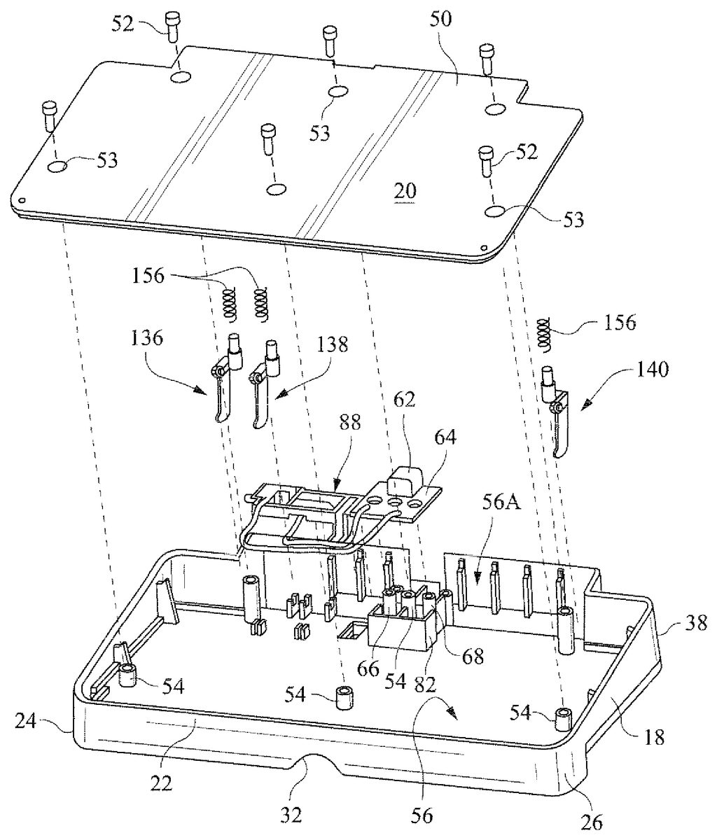
At the rear R of the cradle10, the peripheral edge wall18is expanded rearwardly and vertically to form a “sub-housing”34. The sub-housing34is located substantially centrally of the length of the cradle, such that the peripheral edge wall18remains flush with the upper surface14through the rearward corners36,38, providing a user benefit as described further herein. Thus, the sub-housing34extends rearwardly beyond the rear peripheral wall edge portions40,42(seeFIGS. 2 and 3) a distance defined by sub-housing side wall portions44,46and extends laterally a distance defined by sub-housing rear wall portion48. To accommodate the sub-housing34, the plate20is formed with an extended portion50(FIGS. 2 and 6). In the exemplary embodiment, screws52(FIG. 6) may be inserted through holes53in the plate20and threaded into plural internal housing posts54to secure the flat plate20(or second housing component) to the upper surface/peripheral wall14/18(or first housing component).
It will be appreciated that the cradle housing12provides a substantially closed interior chamber56that includes an expanded space56A provided by the sub-housing34(see, for example,FIGS. 6 and 8).
The expanded space56A in sub-housing34, along with a part of the chamber56provide ample room for the internal cradle contacts and a port adapted to receive an AC adapter or charging wire connector58. Specifically, the rear wall portion48of the sub-housing34is provided with an aperture60for accessing an otherwise conventional AC adaptor or proprietary connector port62(seeFIGS. 2 and 5).
With reference now especially toFIGS. 6-10, the port62is mounted on an internal connector board64. To locate and hold the board64in place, a pair of posts66,68are employed on either side of one of the threaded posts54on the underside of upper surface14. The posts66,68are received in apertures70,72in the board64while the middle, threaded post54projects through another aperture80in the board64. To provide further support for the board64, an internal substantially square support wall82, which substantially matches the footprint of the board64, is formed on the underside of the upper surface14, so as to be engaged by the marginal edges of the board. This arrangement provides a rigid support for the board64and the port62, effectively preventing any movement of the board and the port relative to the cradle housing12. A pair of leads84,86connected to the port62extend rearwardly from the board64and connect to a pair of cradle charging contacts as described further below (seeFIG. 7).
A substantially flat, rectilinear frame88(also best seen inFIG. 7) is fixed to the underside of the upper surface14adjacent the board64. The frame88includes front and rear walls90,92and first and second end walls94,96. An upstanding actuator button98is integrally formed with end wall94, and an additional or third wall100extends between the front and rear walls90,92. End wall96and third wall100support opposed, horizontal pivot pins102,104which also serve as supports for springs106,108as explained in further detail below. An upstanding frame tab110on an offset portion of the rear wall92supports a second pair of horizontal pins112,114located above and offset from the pivot pins102,104but extending substantially parallel thereto. The first spring106is wound about the pivot pin102, extending rearwardly and under the wall92, then extending vertically and wound around the pin112. A remote or distal end of the spring106is bent into a wedge or arrow-shaped portion116(see, for example,FIGS. 12,15A and15B), and terminates at a transverse free edge118. Similarly, the second spring108is wound about the pivot pin104and pin114, with the distal end of the spring108bent into a wedge or arrow-shaped portion120, terminating at a transverse free edge122. Leads84,86are joined to the springs106,108at the pivot pins102,104, respectively. The wedge or arrow-shaped portions116,120of the springs106,108serve as the cradle charging contacts, and they are moveable as the frame88pivots in response to depression of the button98as described further herein.
With particular reference now toFIGS. 8-10, it may be seen that when the frame88is mounted in the interior of the cradle housing12, pivot pins102,104are seated in fixed bearings124,126, respectively, on the underside of upper surface14. Note also a third pivot pin128, axially aligned with pivot pins102,104and extending from the frame end wall94(extending away from the button98) is seated in a third fixed bearing130(FIG. 10). On assembly, the charging contacts116and120are located in the upper portion of the sub-housing34, aligned with contact slots S1and S2provided in a forward wall portion132of the sub-housing34, and the button98projects through an opening134formed in the top surface14(see, e.g.,FIGS. 1,4,11,12,13).
Also located within the sub-housing34are plural (three in the exemplary embodiment) game device locators which aid in the proper alignment of the game device G on the charging cradle10. The three game locators136,138and140are located along the forward wall portion132at one end of the sub-housing34and another forward wall portion142at an opposite end of the sub-housing. The three locators136,138and140can be seen inFIGS. 1,4and6, while locators138,140are also seen inFIGS. 11,12and13. The locators are substantially identical (or substantial mirror images), and, therefore, only one will be described in detail. As best seen inFIG. 16, the game locator138, which is supported in the sub-housing34in a generally upright, vertical orientation, is a one-piece component formed to include a horizontally oriented, double-pivot block144having a pair of transversely-oriented coaxial pins146(one shown inFIG. 16) on either side of a center boss148. The block144is offset laterally from a locating arm150extending above the block144and having an angled tip152. A post154extends in an opposite direction from the block144and provides a receptor for a coil spring156.
FIG. 6illustrates generally the assembly of the component parts, and shows the orientation and position of the game locators136,138and140and associated coil springs158,156and160, respectively, noting that the cradle10inFIG. 6is inverted relative to its normal in-use orientation. InFIG. 8, it can be seen that the edge162of the surface14does not extend to the peripheral edge wall18in the area of the sub-housing34, thus leaving space for insertion of the game locators (as oriented inFIG. 6) in a direction indicated by arrow164(FIG. 8), such that, for example, the locating arm150of locator138will be aligned with a corresponding locator slot139in the forward wall portion132, and with the double-pivot block144supported by the double-bearing166(FIG. 8). Similar support arrangements are provided for each of the remaining two game locators136and140. A double bearing for locator136is partially shown at168inFIG. 10, while the double bearing170for locator140is visible inFIG. 9.
After locating the board64and frame88on the underside104of surface14, and with leads84,86held in guide tab pairs172,174, the plate20is secured to the first housing component14/18by means of the screws52inserted through the holes53in plate20and threaded into the various internal, threaded posts54.
With specific reference toFIG. 9, when the plate20is assembled to the upper component of the housing12, the coil springs158,156and160will be supported in substantially identical cylindrical spring receptors176(FIG. 9) on the underside of the plate20, noting that the posts154locate the springs but do not otherwise support the locators. The locators136,138and140are held in their respective bearings168,166and170by mating standards178,180and182on the underside of the plate20, and the pivot pins102,104and128of the frame88are held in their respective bearings by mating standards184,186and188also projecting from the underside of the plate20(seeFIG. 9). Thus, upon assembly, all internal components are fixed in place within the cradle housing12, understanding, however, that the charging contacts116,120and the game device locators136,138and140are able to pivot in response to loading and unloading the game device G relative to the cradle10.
When the cradle10is empty, the tips152of locators136,138and140project from their respective locator slots137,139and141in the front wall portions132and142of the sub-housing34as shown in FIGS.1and11-13. At the same time, the cradle charging contacts116and120are located so as to be substantially flush with (or slightly behind) contact slots S1and S2(seeFIG. 11andFIG. 13) so that when not in use, the charging contacts are protected from damage due to, for example, unintended impacts.
With the aid of schematic drawings shown inFIGS. 15A and 15B, the manner of operation of the actuator button98may be more easily understood.FIG. 15Ashows the button98in its normal state, projecting above the upper surface14of the cradle, and with the cradle charging contact116retracted so as to be substantially flush with the wall portion132of the sub-housing34. The manner in which the spring106is wound about the pin112and pivot pin102cause the frame88and button98to be biased in a clockwise direction to the normal, non-use state shown inFIG. 15A. When the button98is depressed upon loading the game device G onto the cradle upper surface14as shown inFIG. 15B, the frame88and button98rotate in a counterclockwise direction (relative to the orientation inFIG. 15A), causing the cradle charging contact116to project outwardly from the slot S1and into the game device charging port190on the rear peripheral edge192of the game device G (seeFIGS. 13 and 14) where it engages a stationary, flat game device charging contact191(seeFIG. 14). After charging is completed, as the game device G is removed from the cradle10, the frame88will rotate in the opposite direction, withdrawing the cradle charging contact116from the game device charging port190and returning to the normal state shown inFIG. 15A. In this regard, note that when the cradle charging contact116is extended, the spring106is distorted (see the encircled area107inFIG. 15B), thus creating a bias that assists in returning the contact116to the retracted position. While the above description focuses on the cradle charging contact116, it will be understood that the second cradle charging contact120moves simultaneously and in exactly the same manner as the cradle charging contact116, moving into the out of engagement with the second charging contact195(seeFIG. 14) in the port194. It will be appreciated that the specific cradle contact configuration and the manner of interconnection with the frame88and the actuator button98, which results in the automatic engagement of cradle contacts with game device contacts, may vary to include equivalent structures known to those of ordinary skill in the art.
Now considering just the locator138, and with reference to the partially schematic representation inFIG. 17A, the pivot and spring mounting of the game locator138causes the locating arm150to be biased in a clockwise direction, so that upon assembly, the tip152of the locating arm projects outwardly from its respective locator slot139in the wall portion132. Thus,FIG. 17Ashows the game locator138in its normal position, before a game device G is loaded onto the cradle10.
FIG. 17Bshows how the game locator138is pivoted counterclockwise as the game device G is loaded onto the cradle, andFIG. 17Cshows the game device locator138biased again in a clockwise direction with the tip152of the locator arm150engaged within a recess196(shown in phantom) provided in the game device G. The remaining two game device locators136and140operate in an identical manner, cooperating with two other recesses198,200(FIG. 14) provided in the game device G as described further below.
With reference again to, for example,FIGS. 1-5,11,13,14and18-21, it is another feature of the exemplary but nonlimiting embodiment that an upper center portion of the sub-housing34comprises an openable panel202including a rearward wall204and an top wall206that extends in a forward direction. The panel202is pivotally mounted to the sub-housing rear wall portion148by means of pins208(shown in phantom inFIG. 5). From the closed position shown inFIGS. 1-5and14, the panel202may be pivoted to an open position, partially shown inFIGS. 11-13and20to thereby expose a portion of the rear peripheral edge192of the game device G.
FIGS. 13,14and18-20provide additional details with respect to the interaction between the cradle10and an actual game device G. In the nonlimiting example described herein, the game device G includes a base210surrounded by the peripheral edge212that merges with the rear peripheral edge192; and a cover214pivotally mounted to the base. When the cover204is open as shown inFIG. 19, dual screens216,218and game control buttons220,222and224are visible. The rearward portion of the peripheral edge192(best seen inFIGS. 13,14and20) is provided with the pair of game device charging ports190,194, recesses198,196and200and a game card slot230. In the exemplary embodiment, the recess196is an AC adaptor port. Thus, when the game device G is loaded onto the cradle upper surface14, cradle charging contacts116,120engage within game device charging ports190,194; locators136and140engage within recesses198,200and locator138engages the AC adaptor port or recess196. The locator138may be configured so have a larger tip portion to more effectively engage the AC adaptor port196. In this regard, the locator138may also serve as a stop, taking up any slack between the game device G and the forward edge22of the peripheral edge wall18, thus preventing any shifting in a front-to-back (or vice versa) direction. The remaining locators136and140within the smaller recesses198,200locate the game device G and also limit side-to-side movement of the game device. Thus, the forward curved corner portions24,26of the upstanding edge22combined with the locators136,138and140provide effective means for locating and holding the game device G on the cradle housing in each of two mutually perpendicular directions (front-to-back, and side-to-side). Locating and holding the game G in this manner is important so that effective but not excessive pressure is maintained between the game device charging contacts191,195and the cradle charging contacts116,120.
FIG. 19illustrates that the game device G may be loaded onto the cradle10, and the game cover204pivoted to an open position. Note that because of the lowered height of the peripheral wall18between the shoulders28,30and the sub-housing side walls44,46, the game corner buttons226,228, etc. are left exposed. As a result, the user has the ability to fully operate the game device G while the game device is being charged. Opening the panel202also exposes the game card slot230and thus allows the user to exchange game cards while the game device is being charged. Note also that when the game device G is loaded onto the cradle10, the sub-housing34blocks access to the game device AC adaptor port196so that only the AC adaptor port62on the cradle is available to the user.
It will be appreciated that the shape of the locator arms, the shape of the cradle spring contacts, and the type of connectors utilized, may vary as desired.
Accordingly, while the exemplary embodiment has been described and illustrated in detail, it is clearly understood that the same is by way of illustration and nonlimiting example only, the spirit and scope of the present invention being limited only by the terms of the appended claims.
Claims
- A charging cradle for an electronic game device incorporating a rechargeable battery comprising: a housing having a first surface and a second surface with a peripheral edge wall therebetween, said housing forming a substantially closed interior chamber, said first surface adapted to engage the electronic game device;at least one port in said peripheral edge wall adapted to receive a charging wire connector, said port electrically connected to a pair of charging contacts supported within said substantially closed interior chamber and movable from a normal retracted position where tips of said charging contacts are inside said housing to an in-use extended position where said tips project from said housing;and an actuator button on said first surface operatively connected to said pair of charging contacts, such that in use, upon engaging the electronic game device with said first surface, said button is depressed, causing said pair of charging contacts to move to said extended position to engage corresponding charging ports on a peripheral edge of the electronic game device;and wherein said first surface comprises an upper surface, and said second surface comprises a lower surface, said upper surface sloping upwardly in a front-to-back direction.
- The charging cradle of claim 1 wherein at least a forward edge of said peripheral edge wall extends above said upper surface.
- The charging cradle of claim 1 wherein said pair of charging contacts are adapted to project through respective contact slots formed in a front wall of a sub-housing at a rearward end of said housing, wherein said sub-housing expands said substantially closed interior chamber.
- The charging cradle of claim 3 including at least one locator biased to a normal extended position where a tip of said at least one locator projects from said front wall of said sub-housing, said at least one locator adapted to engage within a recess on the peripheral edge of the electronic game device.
- The charging cradle of claim 4 wherein said at least one locator is between said pair of charging contacts and said recess comprises an AC adaptor port.
- The charging cradle of claim 3 wherein said sub-housing includes a pivotable panel that, when open, permits access to a game card slot in the peripheral edge of the game device.
- The charging cradle of claim 1 wherein said button and said charging contacts are attached to a frame pivotally supported within said substantially closed interior chamber, and said port is supported on a fixed, internal wall adjacent said frame;and wherein a pair of lead wires extend from said port to said charging contacts.
- A charging cradle for a portable, hand-held electronic game device having a base having a peripheral edge provided with a game card slot and a pair of charging ports located in a rearward portion of the peripheral edge, and with game control buttons located at least at two rearward corners of the peripheral edge, the charging cradle comprising: a cradle housing having an upper surface and a lower surface with a peripheral edge wall therebetween thereby forming an interior chamber, said upper surface adapted to support the electronic game device, said peripheral edge wall configured to limit movement of the electronic game device in at least forward and rearward directions relative to the cradle housing when the electronic game device is supported on said upper surface, while permitting user access to the game control buttons and the game card slot;and a pair of charging contacts adapted to engage within said charging ports when the electronic game device is loaded onto said upper surface.
- The charging cradle of claim 8 wherein the electronic game device has a pivotally mounted cover, said cradle housing peripheral edge wall configured to allow the pivotably mounted cover to be opened when the electronic game device is loaded onto said upper surface so that a user can operate the electronic game device when it is loaded onto said upper surface.
- The charging cradle of claim 8 wherein said pair of charging contacts is supported within said interior chamber and movable from a normal retracted position where tips of said charging contacts are substantially flush with said cradle housing to an in-use extended position where said tips project from said cradle housing, said charging cradle further comprising a port in said peripheral edge wall electrically connected to said charging contacts.
- The charging cradle of claim 10 further comprising an actuator button on said upper surface operatively connected to said pair of charging contacts, such that in use, upon engaging the electronic game device with said upper surface, said button is depressed, causing said pair of charging contacts to move to said extended position so as to engage the pair of charging ports on the peripheral edge of the electronic game device.
- The charging cradle of claim 11 wherein said pair of charging contacts are adapted to project through respective contact slots formed in a front wall of a sub-housing at a rearward end of said cradle housing.
- The charging cradle of claim 12 including at least one locator biased to a normal extended position where a tip of said at least one locator projects from said front wall of said sub-housing, said at least one locator adapted to engage a recess on the peripheral edge of the electronic game device.
- The charging cradle of claim 13 wherein said at least one locator is between said pair of charging contacts and said recess comprises an AC adaptor port.
- The charging cradle of claim 12 wherein said sub-housing includes a pivotable panel that, when open, permits access to a game card slot in the peripheral edge of the game device.
- The charging cradle of claim 12 wherein said button and said charging contacts form part of a frame pivotally supported within said cradle housing, said port supported on a fixed, internal wall adjacent said frame, and wherein a pair of lead wires extend from said port to said charging contacts.
- The charging cradle of claim 8 wherein, when said cradle housing is oriented substantially horizontally, said peripheral edge wall extends above said upper surface at a forward end of said cradle housing, and forms part of a sub-housing that extends above said upper surface at a rearward end of said cradle housing.
- The charging cradle of claim 17 wherein rearward corners of said cradle housing adjacent said sub-housing are substantially flush with said upper surface.
- A charging cradle for an electronic game device comprising: a hollow housing including a surface for supporting the electronic game device;a pair of cradle contacts supported in said hollow housing and adapted to engage a pair of corresponding game device charging contacts in the electronic game device, said pair of cradle contacts enclosed within said hollow housing when the electronic game device is not supported on said surface;and means for extending said pair of cradle contacts out of said housing and into engagement with said pair of game device charging contacts when said electronic game device is loaded onto said support surface;and wherein the electronic game device is formed with a peripheral edge, the pair of charging contacts and a game card slot located on a rearward portion of the peripheral edge, the charging cradle further comprising means for permitting access to the game card slot when the electronic game device is supported on said surface.
- The charging cradle of claim 19 and further comprising means for locating the electronic game device on said surface and for limiting movement of the electronic game device in two substantially mutually perpendicular directions.
- A combination electronic game device and charging cradle comprising: an electronic game device having a base defined in part by a peripheral edge, said peripheral edge provided in a rearward portion with a game card slot and at least one recess;said peripheral edge further provided with at least two game control buttons in opposite rearward corners of said peripheral edge;a charging cradle including a cradle housing having an upper surface and a lower surface with a peripheral edge wall therebetween thereby forming an interior chamber, said upper surface adapted to support said electronic game device, said peripheral edge wall configured to limit movement of said electronic game device in at least forward and rearward directions relative to said cradle housing when said electronic game device is supported on said upper surface, while permitting user access to said game control buttons and said game card slot.
- The combination electronic game device and charging cradle of claim 21 wherein said peripheral edge of said electronic game device is provided with a pair of game device charging ports;said cradle housing further comprising at least one port in said peripheral edge wall electrically connected to a pair of charging contacts supported within said interior chamber and movable from a normal retracted position where tips of said charging contacts are inside said cradle housing to an in-use extended position where said tips project from said cradle housing and engage game device charging contacts within said game device charging ports.
- The combination electronic game device and charging cradle of claim 22 and further comprising an actuator button on said upper surface operatively connected to said pair of charging contacts, such that in use, upon loading the electronic game device on said upper surface, said button is depressed, causing said pair of charging contacts to move to said extended position.
- The combination electronic game device and charging cradle of claim 23 wherein said pair of charging contacts are adapted to project through respective contact slots formed in a front wall of a sub-housing at a rearward end of said cradle housing.
- The combination electronic game device and charging cradle of claim 24 including at least one locator biased to a normal extended position where a tip of said at least one locator projects from said front wall of said sub-housing, said at least one locator adapted to engage said at least one recess in said peripheral edge of said electronic game device.
- The combination electronic game device and charging cradle of claim 25 wherein said at least one recess comprises an AC adapter port.
- The combination electronic game device and charging cradle of claim 21 wherein user access to said game card slot is provided by a pivotable panel on said sub-housing moveable between open and closed positions.
- The combination electronic game device and charging cradle of claim 21 wherein the electronic game device has a pivotally mounted cover, said cradle housing peripheral edge wall configured to allow the pivotably mounted cover to be opened when the electronic game device is loaded onto said upper surface so that a user can operate said electronic game device when it is loaded onto said upper surface.
- A charging cradle for an electronic game device incorporating a rechargeable battery comprising: a housing having a first surface and a second surface with a peripheral edge wall therebetween, said housing forming a substantially closed interior chamber, said first surface adapted to engage the electronic game device;at least one port in said peripheral edge wall adapted to receive a charging wire connector, said port electrically connected to a pair of charging contacts supported within said substantially closed interior chamber and movable from a normal retracted position where tips of said charging contacts are inside said housing to an in-use extended position where said tips project from said housing;an actuator button on said first surface operatively connected to said pair of charging contacts, such that in use, upon engaging the electronic game device with said first surface, said button is depressed, causing said pair of charging contacts to move to said extended position to engage corresponding charging ports on a peripheral edge of the electronic game device;and wherein said pair of charging contacts are adapted to project through respective contact slots formed in a front wall of a sub-housing at a rearward end of said housing, and further wherein said sub-housing expands said substantially closed interior chamber.
- The charging cradle of claim 29 wherein at least a forward edge of said peripheral edge wall extends above said upper surface.
- The charging cradle of claim 29 including at least one locator biased to a normal extended position where a tip of said at least one locator projects from said front wall of said sub-housing, said at least one locator adapted to engage within a recess on the peripheral edge of the electronic game device.
- The charging cradle of claim 31 wherein said at least one locator is between said pair of charging contacts and said recess comprises an AC adaptor port.
- The charging cradle of claim 29 wherein said sub-housing includes a pivotable panel that, when open, permits access to a game card slot in the peripheral edge of the game device.
- The charging cradle of claim 29 wherein said button and said charging contacts are attached to a frame pivotally supported within said substantially closed interior chamber, and said port is supported on a fixed, internal wall adjacent said frame;and wherein a pair of lead wires extend from said port to said charging contacts.
Disclaimer: Data collected from the USPTO and may be malformed, incomplete, and/or otherwise inaccurate.