U.S. Pat. No. 8,313,379
VIDEO GAME SYSTEM WITH WIRELESS MODULAR HANDHELD CONTROLLER
AssigneeNintendo Co., Ltd.
Issue DateSeptember 24, 2010
U.S. Patent No. 8,313,379: Video game system with wireless modular handheld controller
U.S. Patent No. 8,313,379: Video game system with wireless modular handheld controller
Issued November 20, 2012, to Nintendo Co., Ltd.
Priority Date: August 22, 2005

Summary:
U.S. Patent No. 8,313,379 describes the Nintendo Wii system. The Wii incorporation of motion controls into a video game system. Motion controls were not a new concept in video games, but the Wii certainly push motion controls into the mainstream. The Wii utilized a small remote and IR sensor bar to track a users movement. The IR sensor bar would be place usually on top of or below the television. A user would point the Wii remote in the direction of the television/sensor bar, and the Wii would generate a cursor on the TV in the corresponding area. When the user moved the remote, the cursor would follow. The Wii remote used accelerometers and infrared detection to determine its position in 3D space when pointed at the sensor bar. Calculating position in a 3D space is essential for games that require movement along a Z axis, such as a boxing game. Despite the complexity it took to track a user’s movement, the motion controls were simple to understand.
The Wii was a hugely successful console for Nintendo, selling around 100 million units. A big reason for the Wii’s success was the accessibility. The motion controls made playing video games simple for the non-gamer. A person could easily understand that to play a golf game only required swinging the Wii remote like a golf club. The Wii had a significant impact on the video game industry. Shortly after the Wii launched, Microsoft and Sony introduced their versions of motion controls. Nintendo still uses a form of motion control in its current system, the Nintendo Switch, though the system does not require motion controls to operate.
Abstract:
A home entertainment system for video games and other applications includes a main unit and handheld controllers. The handheld controllers illumination emitted by emitters positioned at either side of a display, and information derived from the sensed illumination is used to calculate the orientation of the controllers. The controllers can be plugged into expansion units that customize the overall control interface for particular applications including but not limited to legacy video games. Further, the controllers can be used in one-handed or two-handed modes of operation.
Illustrative Claim:
1. A handheld controller operable in a one hand mode of operation and a two hand mode of operation, said controller for use in wirelessly communicating with an electronic game machine having an associated display screen, a first light emitting marker and second light emitting marker each mounted spaced from, but in the vicinity of, the display screen, said handheld controller comprising: an elongated housing having an upper surface, a lower surface, a forward end, a rearward end and a longitudinal axis defining at least one longitudinal center line, and sized to be operable by one hand of a user; a first set of game controls proximate said forward end of said housing; a second set of game controls proximate said rearward end of said housing; said first set of game controls and said second set of game controls being operable in use in a two hand game playing mode of operation, wherein during said two hand game playing mode said first set of game controls are disposed so as to be actuated by one thumb of a user and said second set of game controls are disposed so as to be actuated by the other thumb of the user, and wherein said first and second sets of game controls are actuated in use by the cooperative action of the user’s thumbs; the lower surface of said housing having a concave portion provided with a trigger switch; a processor enclosed within said housing; an imaging device located in said forward end of said housing at least substantially aligned with said longitudinal center line and including a filter, a lens, an image sensor and an image processing circuit, wherein the image sensor, in use, detects light from the first light emitting marker and the second light emitting marker and generates image data, and wherein the image processing circuit, in use, receives and processes said image data and generates position data related to positional coordinates of the first light emitting marker and the second light emitting marker, and wherein the image processing circuit outputs the position data to said processor; at least said trigger switch and said imaging device being used in a one hand game playing mode of operation, wherein game play is controlled by the user holding the controller in one hand; linear accelerometer circuitry for detecting acceleration of the controller along each of three axes and for generating acceleration data along each of said three axes, said linear accelerometer circuitry being, in use, in communication with said processor; and a wireless communication device disposed within said housing and operatively connected to said processor and operable, in use, to transmit signals to said electronic game machine representing operational states of at least said first set of operational controls, said second set of operational controls, said trigger switch, said position data, and said acceleration data.
Illustrative Figure
Abstract
A home entertainment system for video games and other applications includes a main unit and handheld controllers. The handheld controllers illumination emitted by emitters positioned at either side of a display, and information derived from the sensed illumination is used to calculate the orientation of the controllers. The controllers can be plugged into expansion units that customize the overall control interface for particular applications including but not limited to legacy video games. Further, the controllers can be used in one-handed or two-handed modes of operation.
Description
DETAILED DESCRIPTION Example Overall Exemplary Illustrative Non-Limiting System FIG. 1shows an illustrative, exemplary non-limiting implementation of a video game system10(sometimes referred to simply as “system10”). System10includes a main unit12sometimes also called a “console.” Main unit12executes applications including video game software, and generates images for display on the display screen14of a conventional home color television (TV) set or other display device16. Main unit12also generates sound for reproduction by the TV set16. People generally indicated at18can interact with the video game play to control or affect the images and the progression of the game or other application. Main unit12in the exemplary illustrative non-limiting implementation can be used to play a variety of different games including driving games, adventure games, flying games, fighting games, and almost any other type of game one might think of. The video game software that main unit12executes may be delivered on bulk storage devices such as optical disks, semiconductor memory devices or the like; it may be downloaded into the main unit12over a network; or it may be provided to the main unit in any other desired manner. Main unit12may also be capable of performing applications in addition to video games (e.g., movie playback, email, web browsing, or any other application one can imagine). A security system built into main unit12may ensure that only authorized or authentic applications are executed. More specifically,FIG. 1shows people18(“video game players”18a,18b) interacting with main unit12to play a video game. While two players are shown, any number of players may interact with the main unit12at any given time. In the exemplary illustrative non-limiting implementation shown, each video game player18a,18bholds and operates a wireless handheld control unit (“controller”)20(indicated as20aand20b, respectively). The players18aand18boperate these controllers20to generate input signals. The controllers20communicate their input signals wirelessly to main unit12. Such wireless communications can be by any convenient wireless ...
DETAILED DESCRIPTION
Example Overall Exemplary Illustrative Non-Limiting System
FIG. 1shows an illustrative, exemplary non-limiting implementation of a video game system10(sometimes referred to simply as “system10”). System10includes a main unit12sometimes also called a “console.” Main unit12executes applications including video game software, and generates images for display on the display screen14of a conventional home color television (TV) set or other display device16. Main unit12also generates sound for reproduction by the TV set16. People generally indicated at18can interact with the video game play to control or affect the images and the progression of the game or other application.
Main unit12in the exemplary illustrative non-limiting implementation can be used to play a variety of different games including driving games, adventure games, flying games, fighting games, and almost any other type of game one might think of. The video game software that main unit12executes may be delivered on bulk storage devices such as optical disks, semiconductor memory devices or the like; it may be downloaded into the main unit12over a network; or it may be provided to the main unit in any other desired manner. Main unit12may also be capable of performing applications in addition to video games (e.g., movie playback, email, web browsing, or any other application one can imagine). A security system built into main unit12may ensure that only authorized or authentic applications are executed.
More specifically,FIG. 1shows people18(“video game players”18a,18b) interacting with main unit12to play a video game. While two players are shown, any number of players may interact with the main unit12at any given time. In the exemplary illustrative non-limiting implementation shown, each video game player18a,18bholds and operates a wireless handheld control unit (“controller”)20(indicated as20aand20b, respectively). The players18aand18boperate these controllers20to generate input signals. The controllers20communicate their input signals wirelessly to main unit12. Such wireless communications can be by any convenient wireless method such as radio transmission, infrared, ultraviolet, ultrasonic or any other desired technique. Wireless peripherals could include Bluetooth, 802.11 (WiFi), HiperLAN/1, HiperLAN/2, HomeRF, VWB, WiMax or other. In other implementations, cords or cables could be used to connect controllers20to main unit12.
In the exemplary illustrative non-limiting implementation of system10shown, players18a,18boperate handheld controllers20a,20b, respectively, in various ways to provide input signals to main unit12. For example, the players18a,18bmay depress buttons or otherwise manipulate other controls on controllers20a,20b, respectively, to generate certain input signals. The effect of such control manipulations in the exemplary illustrative non-limiting implementation depends, at least in part, on the particular software that main unit12is executing. For example, depressing a certain button may provide a “start game” or “pause game” in some contexts, and may provide different functions (e.g., “jump character”) in other contexts.
In the illustrative exemplary non-limiting implementation shown, controllers20have internal capabilities for detecting position and/or orientation. In the exemplary illustrative non-limiting implementation, players may change the orientation or position of controllers20to generate input signals. Controllers20may sense position and/or orientation and report that information to main unit12. Main unit12may use that information to control or affect video game play or other functionality.
In one exemplary illustrative non-limiting implementation, each of the handhold controllers20a,20bmay include an internal position, attitude or orientation sensor that can sense the position, attitude and/or orientation of the controller relative to the earth's gravitational force. Such a sensor may for example comprise a 3-axis accelerometer that can sense orientation (or changes in orientation) of the controller relative to the direction of earth's gravitational pull. The output of such a sensor may be reported to main unit12and used, for example, to control motion of a character displayed on display screen14.
In addition, the exemplary illustrative non-limiting implementation of system10shown inFIG. 1includes wireless emitters22(including emitters22aand22b). These wireless emitters may be placed on each side of display screen14in alignment with the edges of the screen. The wireless emitters22may, for example, each comprise one or more light emitting diodes (LEDs) or other devices24(including devices24aand24b) that emit infrared or other electromagnetic or other radiation.
In one exemplary illustrative non-limiting implementation, the energy that emitters22emit has a wavelength or other characteristic that allows the radiation to be readily distinguished from ambient radiation. In the exemplary illustrative non-limiting implementation, handheld controllers20each detect the radiation emitted by emitters22and generate signals indicative of the controller's relative position and/or movement. Multiple controllers20can sense the same emitted radiation and generate different signals depending on the position or movement of that particular controller. Controllers20report the relative position and/or movement signal to main unit12. Main unit12may take any appropriate action in response to such signals such as, for example, moving, rotating or otherwise changing a game character or other object or background on the display screen14, scrolling a screen shot, selecting a different game function, or taking other actions.
In the exemplary illustrative implementation shown, the emitters22are added or retrofitted onto a conventional color television set16by, for example, using an adhesive to attach the emitters onto the top housing of the television set on the extreme left and right of the television set housing, in alignment with the edges of display screen14. In this exemplary illustrative non-limiting implementation, emitters22can be connected to main unit12by cables or wires run behind the television set16. In other implementations, emitters22could be built-in to television set16or mounted separately (e.g., on a set top box or otherwise). In still other implementations, emitters22could possibly be replaced with small reflective surfaces attached by adhesive to corners of display screen14, and controllers20could emit electromagnetic radiation and receive reflections from the reflective surfaces (e.g., whose angle of incidence is equal to angle of reflectance). In still other implementations, controllers20could emit electromagnetic radiations and emitters22could include sensors that sense the emitted radiation. Other implementations are possible.
Example Illustrative Non-Limiting Handheld Controller Design
FIG. 2shows a perspective view of an exemplary illustrative non-limiting implementation of a first controller20. Controller20includes a housing26that is graspable by one hand. Controller20in the exemplary illustrative non-limiting implementation is compact and has a solid rugged feel to it. It can be dropped onto a hard surface without breaking. Portions of its housing26are curved to fit comfortably into the hand (seeFIGS. 2A-2F).
As shown inFIG. 2A, the thumb can be positioned to operate controls on a top control surface28while the fingers are comfortably wrapped around the controller's bottom surface30. As explained further below, the digits of the hand (including the thumb) can operate the different controls arrayed on a top control surface28and elsewhere on the controller without fatigue and without wasted or undue motion. The controller20is small and lightweight enough to be comfortably held and supported for long periods of time without fatigue. Controller20is dimensioned to exactly and comfortably fit the average hand—not too small, not too big. The controls are arranged such that the controller20can be operated equally easily by the right hand or the left hand.
The top control surface28of the housing26(FIG. 2) provides an array of controls depressible with the digits (fingers and/or thumbs) of the user's hand. In one illustrative non-limiting implementation, the user may operate a direction switch32with a thumb or forefinger to indicate a direction in two dimensions. In the illustrative non-limiting exemplary implementation shown, the directional switch32may comprise a switch surface34that can be rocked in different directions to provide different direction signals. The simplest form of such a directional switch32may comprise a so-called “cross switch” (a switch in the shape of a cross) that can be rocked in four different directions to provide four different, mutually exclusive direction signals (i.e., up, down, left, right). A somewhat more flexible form of a directional switch32may comprise a circular switch surface36(shown in phantom) that can be rocked in any of a number of different directions to provide corresponding different control signals indicating for example twelve, sixteen or more different directions (A switch of this type is described later in connection with another controller embodiment). Other directional switch configurations could be used to provide a much higher number of directional inputs approaching, equaling or exceeding the number of signals from an analog or digital joystick. A touch or “joy” pad, a pointing stick, a trackball, or other input device could be used instead of or in addition to a switch. If a joypad were used, it could likely be operated in a direction-indicating mode as opposed to a “drag displacement” mode. Other arrangements could include touch sensitive display(s) or other types of displays.
Top control surface28in the exemplary illustrative non-limiting implementation also provides a pair of thumb-operated control switches38a,38b. These control switches can be oriented as shown, or they could each be rotated, say 45 degrees, so as to be angularly displaced from one another (for example, seeFIGS. 8A-9E) in order to expose more surface area to a thumb positioned to operate either control switches38a,38bor directional switch32. Control switches38a,38bcould be used to actuate a variety of game or other functions including for example “start” and “select” functions.
Top control surface28may also provide an additional push button40operated by the thumb for other functionality selection. A slide switch42on the side of housing26may be operated to provide on/off or other functionality. Depending on requirements, a slide switch42could be located on either or both side surfaces of the exemplary controller20.
Top control surface28in the exemplary illustrative non-limiting implementation further provides two additional controls44a,44bthat may comprise indicator lamps or lights. Alternatively, such controls could comprise additional operable controls such as push button switches, so-called “pointing stick” type input devices, or other input devices. These controls44a,44bmay be relatively dormant or little used (while not being subject to accidental operation) when the controller20is operated in the hand positions shown inFIGS. 2A-2E. However, another way of using controller20is to hold the controller in one hand (or place it on a flat surface such a table) and operate its controls with the forefinger and other fingers of the other hand. In such an alternate operating mode, the forefinger could be used to operate controls44a,44bif they are activatable input devices as opposed to indicators.FIG. 2D, for example, shows that in one exemplary illustrative implementation, the user may move his or her thumb forward or backward to access different controls while also operating button56.FIG. 2Eshows the ability to move the thumb side to side to provide different control actuations.FIG. 2Cis similar toFIG. 2Dbut shows the user's index finger removed from button56.FIG. 2Fshows an exemplary illustrative non-limiting implementation whereby the user can hold a handheld controller20′ in both hands and operate it with both left thumb and right thumb simultaneously.
FIG. 3shows an exploded view of a slightly modified controller20with the top control surface (formed by a plate)28removed to reveal a printed circuit board46. Metallic pathways (not shown) and associated solder or other electrical interconnections may be used to electrically interconnect components via PC board46. Various components including integrated circuit chips48(48a-d) (e.g., a wireless RF “Bluetooth” or other communications device, an accelerometer and other components) may be mounted to the printed circuit board46. The printed circuit board46may also serve as a mounting surface for the directional switch32, controls38a,38b,44a,44b, etc. The printed circuit board46in one exemplary illustrative non-limiting implementation provides a rugged fiberglass structure used to both mount and electrically interconnect components of controller20. The same or different printed circuit board46may provide an edge or other connector50for use in electrically connecting controller20to other devices (to be described below).
FIG. 4shows a bottom view of an exemplary illustrative non-limiting implementation of controller20. The bottom view reveals an access plate54for installing one or more small conventional removable/replaceable battery cells (seeFIG. 5).FIG. 4also shows an additional “trigger” type switch56operable by the forefinger when the controller is held in the hand (see, for example,FIGS. 2A,2D,2E). Trigger switch56may, for example, sense pressure to provide a variable input signal that depends on how much pressure the user's forefinger is exerting on the switch. Such a variable-pressure trigger switch56can be used in a video game to fire weapons, control the speed of a vehicle in a driving or space game, or provide other functionality.
In the exemplary illustrative non-limiting exemplary implementation shown, the trigger switch56is disposed on an angular surface58of the bottom surface30of controller20within a V-shaped depression60located near the front distal end62. This V-shaped depression60(or concave portion) is dimensioned to comfortably provide a resting and grasping slot for the forefinger which may be slightly rotated and pulled toward the user between a resting position (seeFIG. 2C) and an actuation position (seeFIG. 2A). With the middle, ring and pinkie fingers wrapped around and grasping the curved center64and rear66portions of the controller's bottom surface30(formed as part of a lower housing portion68) and the forefinger comfortably engaged within the V-shaped depression60, the user feels quite comfortable holding and operating controller20with one hand and positioning and aiming it precisely in desired directions.
FIG. 5shows an exploded view of controller20ofFIG. 4with the lower housing portion68removed to expose internal components such as removably replaceable batteries70a,70band associated holders/contacts72a-72d, and trigger switch56. While two batteries70a,70bare shown inFIG. 5, any number of batteries (e.g., one, three, etc.) can be used depending on weight, power and other requirements. Note that to replace batteries70a,70b, the user would not usually remove the lower housing68, but rather would simply remove the access plate54. In other configurations, the controller20might be rechargeable and batteries70a,70bcould be of the nickel-cadmium or other type that do not require routine replacement. In such exemplary configuration, the controller20could be placed into a charging station to recharge the batteries70a,70binstead of expecting the user to replace the batteries. WhileFIG. 5shows a separate edge connector50, it is possible that the edge connector could be formed by a distal edge of the printed circuit board46.
Example Illustrative Non-Limiting Optical Pointing Device Motion Detection
FIG. 6shows a front perspective view of controller20illustrating an additional sensing component (or motion tracking sensor)74also shown inFIG. 5. Sensor74in the exemplary illustrative non-limiting implementation is disposed on the “nose” or front surface76of controller20so that it points forward, looking down a pointing axis P. The direction of pointing axis P changes as the user changes the orientation of controller20. It is possible to provide a pivot mechanism78(seeFIG. 6A) to allow the user to pivot the nose portion80up and down to provide better ergonomics (e.g., the user could be sitting on the floor below the level of the emitters24a,24b(FIG. 1) and still be able to point directly forward, with the axis P of sensor74being aimed upwardly). This arrangement has the same effect as the embodiment illustrated inFIG. 39discussed further herein.
Sensor74in the exemplary illustrative non-limiting implementation comprises an infrared-sensitive CCD type image or motion tracking sensor. Sensor74may comprise a one-dimensional line sensor or it could comprise a 2D sensor such as for example a low resolution monochrome CCD or other camera. Sensor74may include a lens and a closely coupled digital signal processor to process incoming images and reduce the amount of information that needs to be conveyed to main unit12. In one exemplary non-limiting implementation, sensor74may include a 128 pixel by 96 pixel relatively low resolution monochrome camera, a digital signal processor and a focusing lens. More than one such sensor could be used if desired.
In the exemplary illustrative non-limiting implementation, sensor74gives controller20optical pointing capabilities. For example, movement of the controller20can be detected (e.g., by the controller itself) and used to control what is being displayed on display screen14. Such control could include for example scrolling of the screen, rotation or other reorientation of display objects in response to rotation/reorientation of controller20, and other responsive interactive displays. Such control may provide a better moment arm as compared to a joystick.
FIGS. 6B-6Hshow an additional exemplary non-limiting illustrative implementation of a handheld controller82with a different control configuration on the top surface of the controller. The controller is similar to the controller20(FIGS. 2 and 3) except as otherwise noted. This variation of the controller20includes a power button84which may be used to activate power on the main unit12. A cross switch86provides directional input. An “A” button88provided rearward of the cross switch86, on the upper surface85of the housing87can be operated by the thumb instead of the switch86to provide a momentary on-off control (e.g., to make a character jump, etc.). By moving the “A” button88to the top surface85the button may be generated quickly and reliably, particularly desirable since the “A” button is operated more frequently than the “B” button.
The direction switch86and the A button88correspond to the first operating portion in this embodiment. Accordingly, the direction switch86and the A button88are a key top pushed in a direction orthogonal to the first plane (defined by surface85) and a push switch having contacts (not shown) operated by the key top. Start and select buttons90,92may be provided for example to start game play, select menu options, etc. A menu button94(which may be recessed to avoid accidental depression) may be provided to display or select menu/home functions. “X” and “Y” buttons96,98may be used to provide additional directional or other control. Light emitting diodes or other indicators100(a-d) may be used to indicate various states of operation (e.g., for example to designate which controller number in a multi-controller environment the current controller is assigned). A connector102is provided to connect the controller to external devices.FIG. 6Cshows an underneath side perspective view,FIG. 6Dshows a top plan view,FIG. 6Eshows a side plan view,FIG. 6Fshows a bottom plan view,FIG. 6Gshows a front plan view, andFIG. 6Hshows a rear plan view of the controller82.
Moreover, in this embodiment, as understood well fromFIG. 6Eespecially, a height H1from the first plane85of the key top of the cross switch, i.e. the direction switch86is made higher as compared with a height H2from the first plane85of the key top of the A button88. That is, the direction switch86is set to be higher than the A button88. This aims to prevent the A button88from being pushed by accident while the cross key, i.e. the direction switch86is operated.
The start switch90and the select switch92are arranged in one straight line in a direction orthogonal to the longitudinal direction (width direction), and also a menu switch94is provided between them. The menu switch94is used to select a menu item of a game to be executed by means of the controller82(for example, a one-person play mode, a match-up mode, etc.) and to switch the game mode instantly to the menu to be provided immediately after the startup of the game machine or the like. The center of the menu switch94is aligned with that of the A button88in the width direction of the housing87, and the start switch90and the select switch92are arranged at positions with uniform spacing at left and right from the menu switch94.
With such a button layout as mentioned above, in manipulating the controller82with the right hand, for example, the player can operate the select switch92quickly just by sliding the thumb placed on the A button88without having to bending the thumb. Additionally, in the case of operation with the left hand, the start switch90is a switch suitable for a quick operation in the same manner. Accordingly, it is possible to perform a quick operation regardless of whether the user is right-handed or left-handed, by making a change to the assignments of the select switch92and the start switch90through the use of a software program or the like.
Besides, the menu switch94and the power switch84are provided in such a manner as to be caved in or buried in holes formed on the upper surface85of the housing87so that they are invisible from a side view as shown in6E. These switches84and94are caved because, although they may be operated only on specific occasions such as the time of starting the game, operating these switches by accident during the game would cause some inconvenience such as data loss, and thus these switches are designed to be capable of being intentionally operated at the game start but incapable of being unconsciously operated during the game.
Furthermore, in the controller82of this embodiment, the LEDs100a-dfor indicating the controller numbers are provided as with the controller ofFIG. 23. However, the LEDs821to824ofFIG. 23embodiment are provided at one end (front end) of the housing87, whereas those of this embodiment are arranged at the other end (rear end) of the housing87.
The concave portion60is formed on the lower surface32of the housing87, at a position approximately corresponding to the position of the above mentioned direction switch86, on the side opposite to the holding portion in the longitudinal direction. In the preceding embodiments, the concave portion60has a valley with a plane parallel to the top surface or first plane28, and in this embodiment, the concave portion34has no valley and includes the first inclined surface61and the second inclined part63that have gentle inclination. Also, the B button56is provided on the first inclined surface61extending in the direction of the holding portion. In addition, the B button56is provided at a position corresponding to the direction switch86and the A button88forming the first operating portion. Besides, the corresponding position denotes a position where the B button56is arranged close to the direction switch86and the A button88when viewed through the upper surface of the housing87.
While the A button may be arranged on the lower surface of the housing, the A button of this embodiment is arranged at a position easier to press. Thus, button88is assumed to be the frequently-used A button and the switch56on the lower surface30of the housing is assumed to be the B button, which makes button operation easier.
Additionally, in this embodiment, the B button56corresponds to the second operating portion. The B button56therefore has a key top to be pushed in a direction perpendicular to the inclined surface61but non-perpendicular to the first plane85, and a contact (not shown) turned on or off by the key top.
Moreover, in this embodiment, an angle of inclination of the second inclined surface63extending toward the front end of the housing87, with respect to the first plane85is set as to be smaller than an angle of inclination of the first inclined surface61with respect to the first plane85, as can be well understood fromFIG. 6BandFIG. 6E. That is, the second inclined surface63has gentle inclination as compared with the first inclined surface61. In this manner, by making the second inclined surface40more gentle in inclination than the first inclined surface61, there are such advantages that it is easier to hold the controller with both hands as shown, for example, inFIG. 2F, and it is possible to take the index finger properly off the B button56because the finger can be sufficiently moved in the direction of the takeoff.
Furthermore, as can be understood fromFIG. 6D and 6I, because of a layout of the start switch90, the menu switch94and the select switch90arranged in one horizontal straight line, in this embodiment, a wireless module95is arranged on the right side of the housing87in the width direction. Also, the power switch84is provided on the left side of the housing87of the substrate97in the width direction, in contrast to the preceding embodiments, and the antenna pattern99is arranged at the front end on the right side of the substrate97in the width direction. As stated above, by arranging the antenna pattern99at the front end on the right side of the housing87in the width direction, there is such an advantage that, even in the case of holding with both hands as shown inFIG. 2F, the emission of weak radio waves from the antenna99is not affected by the hands holding the housing87. That is, the antenna pattern99is arranged on the side opposite to the hands holding the controller82, in the width direction of the housing87.
Besides, in the embodiment ofFIG. 6BtoFIG. 6I, the switch56provided in the concave portion60on the lower surface of the housing87is the B button. Alternatively, the B button56may be replaced with an operating means having the functions of the Z button. In addition, the Z button is used as a trigger switch in a shooting game, for example, and also operated on occasions when a non-player object is to be targeted by a player object (a so-called Z-targeting feature), etc.
In the exemplary illustrative non-limiting implementations described above, sensor74is designed and configured to sense the emitters22a,22bshown inFIG. 1.FIGS. 7A,7B show that sensor74has a certain well defined field of view (FOV) symmetrical with the sensor pointing axis P. For example, the sensor74may have a field of view of about 20.5 degrees on each or every side of pointing axis P (this particular field of view angle is a design choice; other choices are possible in other configurations). Such well defined field of view provides an acute triangularly shaped (or cone-shaped for 2D sensor configurations) viewing area that sensor74can “see”—with the base of the triangle increasing in length as distance from the controller20increases. Sensor74also has a well defined sensitivity such that it can only “see” IR emissions above a certain range of intensity. Emitters22(in this case LED emitters or devices24a,24b) are designed in the exemplary illustrative non-limiting to provide sufficient output power and beam spreading consistent with the sensitivity of sensor74such that the sensor can “see” the emitters at ranges consistent with how video game players arrange themselves in a room relative to a television set16(taking into account that a player may sometimes sit close to the television when playing by himself, that players may be sitting on the floor, standing, sitting on chairs or couches or other furniture, etc.).
In more detail,FIG. 7Ashows that in the exemplary illustrative non-limiting implementation, the overall field of view of sensor74is wider than the typical separation of LED emitters24a,24band is also wider than beam width of each emitter. In one exemplary illustrative non-limiting implementation, the ratio of the beam spreading angle (e.g., 34 degrees) of the beams emitted by LED emitters24to the field of view (e.g., 41 degrees) of sensor74may be approximately 0.82 (other ratios are possible). Plural LED emitters24can be used at each emission point to provide a wider beam (horizontal field of view) than might otherwise be available from only a single emitter, or a lens or other optics can be used to achieve desired beam width.
At an average distance from controller20to television set16(FIG. 1) and associated LED emitters24and assuming a maximum television screen size (and thus a maximum physical separation between the emitters), such a ratio may maximize the displacement of two radiation “dots” or points appearing on the CCD sensor array104that sensor74comprises. Referring toFIG. 7Afor example, when the central axis of sensor74is directed centrally between displaced LED emitters24(note that in one exemplary illustrative non-limiting implementation, the emitters are disposed on either side of the television display and are therefore relatively far apart relative to the resolution of the image being generated), the CCD array104that sensor74defines will register maximal illumination at two points near the ends of the sensor array. This provides a higher degree of resolution when the sensor74's central axis P is displaced relative to the center of separation of the LED emitters24(seeFIG. 7B) even when using a relatively low resolution CCD imaging array (e.g., a 128-cell long sensor array). Note that while a linear array104is illustrated inFIGS. 7A,7B for sake of convenience, a rectangular array could be used instead.
In the illustrative, exemplary non-limiting implementation shown, it is unnecessary to modulate or synchronize LED emitters24, although it may be desirable to power down the emitters when not in use to conserve power usage. In other arrangements, however, synchronous detection, modulation and other techniques could be used.
The exemplary illustrative non-limiting implementation of controller20(and82) and/or main unit12includes software or hardware functionality to determine the position of controller20(and82) relative to LED emitters24, in response to the illumination maxima sensed by sensor74. In one example illustrative non-limiting implementation, controller20,82include an on-board processor coupled to the sensor74that interprets the currently detected illumination pattern, correlates it with previous sensed illumination patterns, and derives a current position. In another example illustrative non-limiting implementation, controllers20,82may simply report the sensed pattern to main unit12which then performs the needed processing to detect motion of controller. The sensor could also be affixed to the human operating the system to provide additional control.
Since it may not be desirable to require end users of system10to measure and program in the precise distance between the LED emitters24and since television sets vary in dimension from small screens to very large screens, controller20(or82) does not attempt to calculate or derive exact positional or distance information. Rather, controller20(or82) may determine movement changes in relative position or distance by analyzing changes in the illumination pattern “seen” by CCD array104.
It may be possible to ask the user to initially point the controller at the center of the television display screen14and press a button, so as to establish a calibration point (e.g., see FIG.7A)—or the game player may be encouraged to point to the center of the screen by displaying an object at the center of the screen and asking the user to “aim” at the object and depress the trigger switch. Alternatively, to maximize user friendliness, the system can be self-calibrating or require no calibration at all.
Differences in the illumination pattern that CCD array104observes relative to previously sensed patterns (see e.g.,FIG. 7B) can be used to determine or estimate movement (change in position) relative to previous position in three dimensions. Even though the CCD array104illumination shown in theFIG. 7Bscenario is ambiguous (it could be obtained by aiming directly at emitter24aor at emitter24b), recording and analyzing illumination patterns on a relatively frequent periodic or other basis (e.g., 200 times per second) allows the controller to continually keep track of where it is relative to the emitters24and previous controller positions. The distance between the illumination points of emitters24and CCD array104can be used to estimate relative distance from the emitters. Generally, game players can be assumed to be standing directly in front of the television set and perpendicular to the plane of display screen14. However, scenarios in which controller20(or82) is aimed “off axis” such that its central axis P intersects the plane of emitters24at an angle other than perpendicular can also be detected by determining the decreased separation of the two maximum illumination points on the CCD array104relative to an earlier detected separation. Care must be taken however since changes in separation can be attributed to changed distance from the LED emitters24as opposed to off-axis. Simpler mathematics can be used for the motion and relative position detection if one assumes that the player is aiming the sensor axis P directly at the display screen14so the axis perpendicularly intersects the plane of the display.
Software algorithms of conventional design can ascertain position of controller20(or82) relative to emitters24and to each logical or actual edge of the display screen14. If desired, controller20(or82) may further include an internal conventional 3-axis accelerometer that detects the earth's gravitational forces in three dimensions and may thus be used as an inclinometer. Such inclination (orientation) information in three axis can be used to provide further inputs to the relative position-detecting algorithm, to provide rough (x, y, z) position information in three dimensions. Such relative position information (or signals from which it can be derived) can be wirelessly communicated to main unit12and used to control the position of displayed objects on the screen.
Another Example Illustrative Non-Limiting Handheld Controller Design
With reference now toFIGS. 8A-9E, a controller106of another embodiment includes a longitudinal housing108molded of plastic or metal, for example. The housing108has a required depth and includes a lower housing portion110having a shape of a flat rectangle with a top-surface opening and a bottom, an upper housing portion112assembled integrally with the lower housing portion110in such a manner as to close up the top-surface opening of the lower housing portion110, and in particular, has a rectangular cross-section on the whole as shown inFIGS. 9A and 9E.
The housing108has a holding portion114and is of size capable of being held by one hand of an adult or child on the whole. Its length L (seeFIG. 9D) in a longitudinal direction (a direction along a center line C1shown inFIG. 9B) is set at 8 to 15 cm, for example, and its width (orthogonal to the longitudinal direction C1) W (FIG. 9D) is set at 2 to 4 cm, for example, respectively.
Alternatively, the shape of the housing108is not limited to a longitudinal shape with a plane rectangle and may be a longitudinal shape with a plane oval or the like. Likewise, its cross-section shape is not limited to a rectangle and may be a circle or other polygons.
A flat main surface of the upper housing portion112constitutes an upper surface116of the housing108. As can be seen well fromFIG. 8AandFIG. 9Bin particular, the upper surface116of the housing108is a rectangle extending along the longitudinal direction of the housing108. Also, the upper surface116is equivalent to a first plane, and a surface or main surface118of the lower housing portion110is equivalent to a second plane opposed to the first plane116. The second plane118is approximately parallel with the first plane116. In addition, as viewed inFIG. 9B, an upward direction is assumed to be forward (side of one end) and a downward direction is assumed to be backward (side of the other end) in the longitudinal direction C1of the housing108.
A power switch120is provided on the upper surface116of the housing108, slightly right of center in a width direction of the upper surface116(indicated by the center line C1inFIG. 9B) in the vicinity of the housing front end (one end). The power switch120is intended to turn on or off an electric power source to an associated game machine, for example, game machine196(FIG. 16) by a remote operation.
In this embodiment, a power switch for turning on or off the controller106itself is not provided. The controller106is turned on by operating any one of the operating switches of the controller106, and is automatically turned off if no operation is performed for a predetermined period of time or more.
A direction switch122is provided on the width-direction center line C1of the upper surface116, forward of the longitudinal-direction center of the housing108(indicated by a center line C2inFIG. 9B). The direction switch122is a combined switch of four-direction push switches and center switch, and includes operating portions122F,122B,122R and122L for four directions indicated by arrows, forward (or up), backward (or down), right and left, and also includes a center switch124. The operating portions122F,122B,122R and122L are arranged on a single key top, in a shape of a ring with a turn of 90 degrees among them. By operating any one of them, one of contacts (not shown) which are arranged in a shape of a polygon corresponding individually to these operating portions122F,122B,122R and122L is selectively turned on, thereby selecting any one of the directions of upward, downward, right and left. For example, by operating any one of the operating portions122F,122B,122R and122L, one of those contacts is turned on to make it possible to designate a movement direction of a character or object (player character or player object) capable of being operated by a game player or to designate a movement direction of a cursor.
The center switch124is a single push-button switch and may be used as a so-called “B” button. As is well known, the “B” button124can be used for changing the game mode selected by means of a select switch126described later, canceling the action decided by means of an “A” button, also described later, and so on.
Besides, as is well known, such a combined switch as described in relation to this embodiment is highly utilized for cellular telephones and the like (see http://www.jpo.go.jp/shiryou/s_sonota/hyoujun_gijutsu/small_switch/b-6-2.-htm, for example), and thus a more detailed description of it is omitted.
As stated above, the direction switch122of this embodiment includes the contacts (not shown) arranged in the shape of a polygon (rectangle or rhombus) so as to indicate individual directions (the four directions in the embodiment) so that these contacts are operated by means of the operating portions122F,122B,122R and122L formed on a single key top. Alternatively, the operating portions122F,122B,122R and122L may be provided as individual key tops so that one contact is operated by means of each corresponding key top.
In addition, the direction switch122may be a cross key or a joystick. In the case of the direction switch122as a joystick, an arbitrary direction and position can be designated by turning its tip end 360 degrees in an arbitrary direction or deflecting the same.
As can be seen well fromFIG. 9B, a start switch128and the select switch126having key tops arranged in a shape of the Japanese KATAKANA character “ ” with the width-direction center line C1of the housing108between them are provided on the upper surface116, rearward of the direction switch122. The start switch128is used for starting (re-starting) and pausing a game and the like. The select switch126is used for selecting a game mode, etc.
Additionally, the start switch128and the select switch126may be provided in an arbitrary layout such as one transverse line and one vertical line, not limited to the shape of the Japanese KATAKANA character “ ” presented in relation to the embodiment.
A concave portion130is formed on the second plane118of the lower housing110, at a position approximately corresponding to the position of the direction switch122. The concave portion130is concave-formed so as to reach from one end of the other of the second plane118in a width direction, as can be understood fromFIG. 8BandFIG. 9C. Additionally, strictly speaking, the concave portion130of this embodiment is formed slightly forward of the direction switch122, as can be seen from a contrast betweenFIG. 9BandFIG. 9C. The concave portion130is formed at a position where, when the player holds the controller106, i.e., the holding portion114of the housing108by one hand as described later, the index finger of the same hand naturally falls. Therefore, a width of a valley132of the concave portion130(in the longitudinal direction of the housing108) is formed in a size that allows the index finger to come into there. The concave portion130has two inclined surfaces134and136rising from the valley132. The former inclined surface134is formed with a rise from the valley132toward the rear of the housing108, and conversely, the latter inclined surface136is rising from the valley132toward the front of the housing108.
An “A” button138is provided on the inclined surface134on the rear side of the concave portion130of the lower housing110. The “A” button138is provided at a position corresponding to the direction switch122. Here, the corresponding position means a position where the direction switch122and the “A” button138are arranged close to each other as viewed through from the upper surface of housing108, and more preferably, the direction switch122and the “A” button138are arranged in such a manner as to be at least partially overlapped. As can be seen well from the illustration, the bottom of the valley132is on a plane approximately parallel with the upper surface116, i.e., the first plane of the housing108, and the rear inclined surface134on which the “A” button138is arranged is formed between the bottom parallel surface of the valley132and the holding portion114formed on the rear (other) side of the housing108described earlier. Also, the “A” button138is a push switch having a switch contact (not shown) and a key top for turning on or off the switch contact, and the key top is provided so as to move in a direction perpendicular to the inclined surface134. Therefore, as described later, the player can turn on the “A” button138just by putting his/her index finger or middle finger in the concave portion130and pulling it toward him/her. That is, the index finger or the middle finger can be positioned in the concave portion130, which makes it possible to operate the “A” button138quickly and reliably when needed.
Besides, the “A” button138allows a player character or a player object to perform an arbitrary action such as punching, throwing, capturing (obtaining), riding and jumping. For example, in an action game, the “A” button138makes it possible to designate jumping, punching and manipulating a weapon, etc. Also, in a role-playing game (RPG) or simulation RPG, the “A” button138makes it possible to designate the obtainment of an item, the selection and decision of a weapon and a command, and so on.
In addition, the above stated holding portion114is formed on the housing, backward of the concave portion130, i.e., the “A” button138. As described later, in using the controller106, the controller106, i.e., the housing108is held in such a manner that the player's palm of one hand wraps the holding portion114. At that time, the player can hold stably the holding portion114only by one hand because the controller106, i.e., the housing108is of a size or thickness capable of being held by one hand.
Moreover, the key top of the “A” button138is turned on by pushing it in the direction perpendicular to the inclined surface134, that is, the direction toward the holding portion114. The inclined part134is not perpendicular to the upper surface of the housing108, that is, the first plane116and, in the end, the key top of the “A” button138is pushed in a direction not perpendicular to the upper surface116. On the contrary, the “B” button124and the direction switch122are turned on by pushing them in the direction perpendicular to the upper surface116of the upper housing112. These push directions mean directions in which the index finger and the thumb can apply pressure naturally in holding the holding portion114. This makes it possible to support a periphery of the operating portion continuously by the thumb and the index finger during the operation while holding the holding portion114, and perform the operation in the stable holding state at any time.
Furthermore, an “X” button140and a “Y” button142are arranged on the width-direction center line C1and backward of the longitudinal-direction center C2of the housing108, in a straight line with a spacing between the two. These “X” button140and “Y” button142are used to make adjustments to view point position and view point direction in displaying a three-dimension game image, that is, make adjustments to a position and a field angle of a virtual camera.
A battery cover144is detachably attached to the lower housing110forming the holding portion114, and battery (or batteries)146shown inFIG. 14is stored inside the battery cover144. Thus, the controller106operates with the battery146as a power source. In addition, the battery cover144can be detached by removing an engagement pawl148(FIGS. 8B and 9D) from the lower housing110.
The battery (or batteries)146is relatively heavy and is stored within a range of the holding portion114of the housing108, and thus a center of gravity G (FIG. 9B) is reliably contained within the range of the holding portion114. This makes it possible to perform stably the displacement or movement of the controller106while holding the holding portion114.
An infrared imaging device150forming one part of an imaging information arithmetic unit152(FIG. 14) described later in detail is arranged on a front-end surface154(FIGS. 8A and 9A) of the housing108, and a 32-pin edge connector156is provided on a rear-end surface158(FIGS. 8B and 9E) of the housing108, for example. The connector156is used to attach and connect the controller of this embodiment (the first controller)106to another second controller (described later), and so on.
The controller106is structured in such a manner that it can be held by one hand of the game player, similar to the manner in which the controller20is held as described above in connection withFIGS. 2A-2E.FIGS. 10-12show a state in which the player holds the controller106by his/her hand160. Referring to these drawings, a player's palm160aand balls of middle finger160b, ring finger160cand small finger160dof the one hand160(right hand in the drawings) hold the holding portion114of the housing108in such a manner as to wrap the holding portion114lightly. In the state, a thumb160eof the hand160is positioned on the direction switch122and an index finger160fis positioned in the valley132of concave portion130of the lower housing110. More specifically, the direction switch122is arranged at a position reached by the thumb160eof the hand160holding the housing108, that is, at a position capable of being operated by the thumb160e. The “A” button138is arranged at a position reached by the index finger160fof the hand160holding the housing108, that is, at a position capable of being operated by the index finger160f. Accordingly, the player can operate the direction switch122by the thumb160eand operate the “A” button138by the index finger160fwhile holding the housing108by the hand160. More specifically, the index finger160fis positioned in such a manner as to make contact with a surface of the valley132of the above stated concave portion130formed in the lower housing110. By bending the index finger160ftoward him/her (rightward inFIG. 10) in that state, the user can push the key top of the “A” button138by the ball of the index finger160fin a direction perpendicular to the near-side inclined surface134of the concave portion130. Consequently, the player can operate the “A” button138by the index finger160fwhile holding the housing108by the hand160. Additionally, in the case of this embodiment, the B button128is to be operated by the thumb160eof the one hand160as with the direction switch122, as can be seen well fromFIG. 12Ain particular. That is, in this embodiment, the direction switch122is operated by extending the thumb160eand the B button128is operated by bending the thumb160e.FIG. 12Afor example shows that in one exemplary illustrative implementation, the user may move his or her thumb forward or backward to access different controls while also operating button138.FIG. 11shows the ability to move the thumb side to side to provide different control actuations.FIG. 12is similar toFIG. 10but shows the user's index finger removed from button138.
It will be appreciated that the same manner of holding the controller106applies if the holding hand of the user is a left hand.
In addition, the “A” button138is described above as being operated by the index finger160f. Alternatively, by further providing an “A2” button (not shown) of the same shape as the “A” button138and rearward of the “A” button138, the housing108may be held by the palm160aand the balls of the ring finger160cand small finger160dso that the “A” button138can be operated by the index finger160fand the “A2” button by the middle finger160b, respectively.
As stated above, the controller106of this embodiment, under the state of being held by one hand, allows the first operating portion (the direction switch122in the embodiment) and the second operating portion (the “A” button138in the embodiment) to be easily operated. That is, the controller106of this embodiment makes it possible to operate each of the operating portions with stability while holding the controller106by one hand. Therefore, the player can use the other hand for playing a game or for another purpose. Moreover, since it can be held only by one hand, the controller106can be handled more freely as compared with the case of holding by the both hands. As a consequence, it is possible to perform smoothly the carrying, movement or displacement of the controller106.
Additionally, in the controller106of this embodiment, the position of the first operating portion, for example, the direction switch122provided on the upper surface116of the housing108and the position of the second operating portion, e.g., the “A” button138provided on the lower surface of the housing108correspond to each other on the upper and lower surfaces116and118of the housing108so that the housing108can be caught by the thumb and the index finger (or middle finger) operating these portions, resulting in further stable operations. For example, when the direction switch122is operated by the thumb160e, the housing108is supported from underneath by the index finger160for the middle finger160bpositioned in the concave portion130for operating the “A” button138, which makes it possible to push the direction switch122by the thumb160ein a stable manner. Likewise, when the “A” button138is operated by the index finger160for the middle finger160b, the housing108is supported from above by the thumb160efor operating the direction switch122, which make it possible to push the “A” button138by the index finger160for the middle finger160bwith stability.
Furthermore, in this embodiment, the center of gravity G of the controller106falls across the point of intersection of the width-direction center line C1and the longitudinal-direction center line C2shown inFIG. 9Bor in vicinity thereto. The position of the center of gravity G is contained in a range of the holding portion114, as can be seen well fromFIGS. 9Band C. Therefore, when the controller106is held at the holding portion114, the holding hand160supports the position of the center of gravity G, which allows the holding state to be maintained with greatly high stability. Thus, it is possible to perform further smoothly the movement, carrying or displacement of the controller106for the imaging information arithmetic unit.
FIG. 10shows a state that the index finger160fpresses the “A” button138. When it is not necessary to press the “A” button138, the index finger160fmay be moved off the “A” button138(the same applies to the middle finger160b). That is, as shown inFIG. 12, by pushing the index finger160f(or the middle finger160b) against the front-end inclined surface136of the concave portion130, it is possible to make the housing stable in the state that the “A” button138is released from the index finger160f(or the middle finger160b). Consequently, it is not necessary to change the state of holding the housing108(change a holding manner), depending on whether to press the “A” button138or not.
It will be appreciated that the manner in which the controller is held, and the manner in which the thumb and index finger are used to manipulate the various buttons/switches is essentially the same for all of the controllers described herein, and regardless of the functions described to the buttons (for example, regardless of “A” and “B” button designations).
FIGS. 13 and 14illustrate the controller106with the upper housing112removed from the controller106and the lower housing110removed from the controller106, respectively. As shown inFIG. 13indicating the removal of the upper housing112, a substrate162is attached to an upper end of the lower housing110in such a manner as to seal the upper opening of the lower housing110. The above described power switch120, direction switch122, start switch128, select switch126, “X” button140and “Y” button142are mounted on an upper main surface of the substrate162, and they are connected to a processor164(FIG. 15) constituting a controller circuit by means of appropriate wiring (not shown).
Moreover, an acceleration sensor166and a wireless module168(also shown inFIG. 6I) are assembled on the upper main surface of the substrate162, between the direction switch122and the “X” button140, for example, between the start switch128and the select switch126.
The acceleration sensor166is preferably a three-axis linear accelerometer that detects linear acceleration along each of an X axis, Y axis and Z axis. Alternatively, a two-axis linear accelerometer that only detects linear acceleration along each of an X axis and Y axis (or other pair of axes) may be used in another embodiment depending on the type of control signals desired. As a non-limiting example, the three-axis or two-axis linear accelerometer68may be of the type available from Analog Devices, Inc. or STMicroelectronics N.V. Preferably, the acceleration sensor166is an electrostatic capacitance or capacitance-coupling type that is based on silicon micro-machined MEMS (microelectromechanical systems) technology. However, any other suitable accelerometer technology (e.g., piezoelectric type or piezoresistance type) now existing or later developed may be used to provide the three-axis or two-axis acceleration sensor166.
As one skilled in the art understands, a linear accelerometer, such as acceleration sensor166, is only capable of detecting acceleration along a straight line corresponding to each axis of the acceleration sensor. In other words, the direct output of the acceleration sensor166is limited to signals indicative of linear acceleration (static or dynamic) along each of the two or three axes thereof. As a result, the acceleration sensor166cannot directly detect movement along a non-linear (e.g. arcuate) path, rotation, rotational movement, angular displacement, tilt, position, attitude or any other physical characteristic.
However, through additional processing of the linear acceleration signals output from the acceleration sensor166, additional information relating to the housing108can be inferred or calculated, as one skilled in the art will readily understand from the description herein. For example, by detecting static linear acceleration (i.e., gravity), the linear acceleration output of the acceleration sensor166can be used to infer tilt of the object relative to the gravity vector by correlating tilt angles with detected linear acceleration. In this way, the acceleration sensor166can be used in combination with the processor164(or another processor) to determine tilt, attitude or position of the housing108. Similarly, various movements and/or positions of the housing108can be calculated or inferred through processing of the linear acceleration signals generated by the acceleration sensor166when the housing108containing the acceleration sensor166is subjected to dynamic accelerations by, for example, the hand of a user. In another embodiment, the acceleration sensor166may include an embedded signal processor or other type of dedicated processor for performing any desired processing of the acceleration signals output from the accelerometers therein prior to outputting signals to processor164. For example, the embedded or dedicated processor could be used to convert the detected acceleration signal to a corresponding tilt angle when the acceleration sensor is intended to detect static acceleration (i.e., gravity).
In this embodiment, the acceleration sensor166and processor164function as a position and/or attitude determining means for determining the position and/or attitude of the controller106held by the player with his/her hand. By outputting information on the position and/or attitude through conversion of the acceleration signal output from the acceleration sensor166, in addition to operation signals from the direction switch122, the “A” button138, etc. and obtaining operation signals for position or attitude at the game machine side, it is possible to perform game operations with a high degree of flexibility.
As stated above, by arranging the acceleration sensor166within the housing108so that the acceleration detected by acceleration sensor166can be used to determine the attitude and position of the housing108, i.e. the controller106, the player can easily change the position and attitude of the controller106by moving (turning) the wrist of his/her hand while holding the holding portion114of the housing108by that hand described above with reference toFIGS. 10 to 12. Therefore, according to the controller106of this embodiment, it is possible to utilize not only operation signals from the operating switches120,122,124,126,128,140and142of the controller106but also the position and attitude of the controller106as controller data, allowing further higher degrees of operations.
Moreover, the acceleration sensor166is provided within the housing108of the holding portion114, and in the course of nature, the thumb is placed on the direction switch122and the index finger is placed on the “A” button138, and the remaining fingers support the holding portion. Thus, no variations occur among individuals in the way to hold the controller106, which makes it possible to perform high-precision detection without variations under predetermined criteria. That is, the above mentioned turning operation of the wrist may result in a displacement of a rotational axis due to its rotation. Also, since right-handed rotation and left-handed rotation are asymmetrical, there is a possibility of causing an error. However, by providing the acceleration sensor166within the housing108of the holding portion114as in this embodiment, the displacement of the rotation axis due to its rotation is reduced with a decreased possibility of detection errors.
Additionally, in the embodiment, the acceleration sensor166is set up within a range of the holding portion114of the housing108(see alsoFIGS. 8A,8B). This brings about an advantage that the position and/or attitude determining means can determine the position and/or the attitude with high accuracy. Besides, the position and/or attitude determining means may be arranged at another position within the housing108according to the purpose. For example, as the position and/or attitude determining means is moved backward of the housing108, the amount of change in position and/or attitude due to the displacement of the housing108becomes smaller. On the contrary, as the means is moved forward of the housing108, the amount of change in position and/or attitude due to the displacement of the housing108becomes larger. Consequently, the position and/or attitude determining means may be arranged at the most appropriate position according to required performance.
In another exemplary embodiment, the acceleration sensor166may be replaced with a gyro-sensor of any suitable technology incorporating, for example, a rotating or vibrating element. Exemplary MEMS gyro-sensors that may be used in this embodiment are available from Analog Devices, Inc. Unlike the linear acceleration sensor166, a gyro-sensor is capable of directly detecting rotation (or angular rate) around an axis defined by the gyroscopic element (or elements) therein. Thus, due to the fundamental differences between a gyro-sensor and an linear acceleration sensor, corresponding changes need to be made to the processing operations that are performed on the output signals from these devices depending on which device is selected for a particular application. Due to the fact that the nature of gyroscopes is known to one skilled in the art, as well as the fundamental differences between linear accelerometers and gyroscopes, further details are not provided herein so as not to obscure the remainder of the disclosure. While gyro-sensors provide certain advantages due to their ability to directly detect rotational movement, linear acceleration sensors are generally more cost effective when used in connection with the controller applications described herein.
An antenna pattern (or antenna)170(FIG. 13) is formed on the upper main surface of the substrate162, and the controller106is provided as a wireless controller by the means of the antenna pattern (or, simply, antenna)170and the above mentioned wireless module168. More specifically, the operation signals from the above stated individual switches and buttons120to128,140and142, and the detection data (detection signal) from the imaging information arithmetic unit152and acceleration data (acceleration signal) from the acceleration sensor166are modulated in the wireless module168to weak radio wave signals, and the modulated weak radio wave signals are emitted from the antenna pattern170. Accordingly, the game machine (not shown), by receiving the weak radio waves and performing demodulation and decoding on them, can obtain the operation signals from the above stated individual switches and buttons120to128,140and142, and the detection data from the imaging information arithmetic unit152and the detected acceleration data from the acceleration sensor166. Then, the game machine makes the game progress, based on the signals, data and game programs obtained in such a manner.
In addition, a crystal oscillator172(FIG. 13) provided on the upper main surface of the substrate162is intended to generate a basic clock of a computer or the processor164(FIG. 15) contained in the controller106.
As shown inFIG. 14in which the lower housing110is removed, the imaging information arithmetic unit152is attached to an edge of the front end on the lower main surface of the substrate162, and the connector156is attached to an edge of the rear end thereof. The imaging information arithmetic unit152has the above mentioned infrared imaging device150and an image processing circuit174for processing image data imaged by the imaging device (imaging means)150.
Additionally, the above described “A” button138is attached to the lower main surface of the substrate162backward of the imaging information arithmetic unit152, and the aforesaid battery146is stored further backward thereof. A vibrator176is attached to the lower main surface of the substrate162, between the battery146and the connector156. The vibrator176may be a vibrating motor or solenoid, for example. The vibrator176creates vibrations in the controller106, and the vibrations are transmitted to the player's hand160(FIG. 10) holding it, which realizes a vibration-ready game. Consequently, it is possible to provide the player with a vibratory stimulus.
Besides, as stated above, arranging the vibrator176on the opposite side of the imaging information arithmetic unit152in the longitudinal direction of the housing108would decrease the possibility that the vibrations from the vibrator80affect adversely imaging by the imaging information arithmetic unit152. That is, a longest distance can be secured between the vibrator176and the imaging information arithmetic unit152, which makes it possible to prevent the imaging element of the imaging information arithmetic unit152from being blurred as much as possible.
Besides, in changing the direction of imaging with the imaging means or imaging device150, the player may hold the holding portion114of the housing108by one hand and move the wrist of the hand in that state, as already described with reference toFIG. 10toFIG. 12. At that time, the imaging means150is provided at the front end of the housing108, the thumb is placed on the direction switch122and the index finger is placed on the “A” button138in the course of nature, and the remaining fingers support the holding portion. This makes it possible to perform an imaging operation under predetermined uniform criteria, independent of variations among individuals in the way to hold the controller106.
Here, referring toFIG. 15, a description is given as to electric circuit structure of the controller106of the embodiment as described above.
The imaging information arithmetic unit152has the infrared imaging device150and the aforesaid image processing circuit174for processing image data imaged by the imaging device150. As illustrated, the imaging device150includes a solid imaging element178such as a CMOS sensor and a CCD. An infrared filter (a filter permeable to infrared rays only)180and a lens182are arranged frontward of the imaging element178. Accordingly, the imaging device150generates image data through detection of infrared rays alone. In addition, the image processing circuit174processes the infrared image data obtained from the imaging device150, senses a high-intensity portion, detects the portion's center-of-gravity position and area, and outputs the data on them. The data on the position and area of the high-intensity portion is input from the image processing circuit174to the processor164. Moreover, the operation signals from the aforementioned switches and buttons120to128,140and142are input into the processor164. In addition, the three-axis or two-axis acceleration data (acceleration signal) from the acceleration sensor166is also input into the processor164.
Based on the operation signals from the operating switches120to128,140and142, the processor164detects which one of the operating switches and operating buttons is being operated from time to time. The operation data is output as a sequence of controller data together with the acceleration data and the high-intensity portion data, and is input into the wireless module168. The wireless module168modulates a carrier wave of predetermined frequency with the controller data, and emits the weak radio wave signal from the antenna170.
Besides, the signals and data input through the connector156provided at the rear end of the controller106are also input into the processor164, and processed by the processor164as with the aforementioned signals and data, provided as controller data to the wireless module168, and then output as a weak radio wave signal from the controller106in the same manner.
Additionally, the processor164may be independent from the wireless module168, and, in using a wireless module based on Bluetooth (registered trademark) standard, etc., it may be contained as a microcomputer in the module.
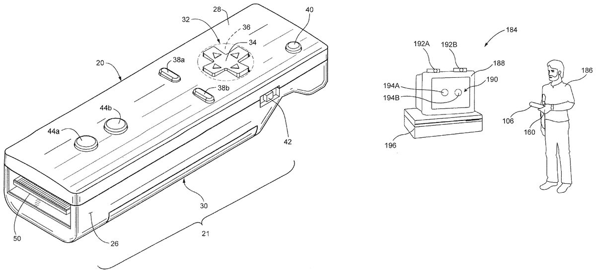
In order to play a game using the controller106in a game system184(seeFIG. 16), a player186holds the controller106(the housing thereof) by one hand160. Then, the player186faces the imaging device150(FIG. 15) of the aforementioned imaging information arithmetic unit152at the front end of the controller106toward a screen190of a display188. At that time, two LED modules192A and192B are set up in a vicinity of the screen190of the display188. Each of the LED modules192A and192B outputs infrared rays. Meanwhile, the infrared filter180(FIG. 15) is incorporated into the imaging information arithmetic unit152of the controller106held by the player, as described above.
The image processing circuit174(FIG. 15) of the imaging information arithmetic unit152obtains information on the positions and areas of the LED modules192A and192B as high-intensity point information, by processing the taken image containing the infrared rays. Data on the positions and magnitudes of the intensity points is transmitted from the controller106to a game machine196by radio (weak radio waves), and received by the game machine196. When the player moves the controller106, i.e. the imaging information arithmetic unit152, the data on the intensity point positions and magnitudes is changed. By taking advantage of this, the game machine196can obtain an operation signal corresponding to the movement of the controller and make the game progress according to that.
In this manner, the imaging information arithmetic unit152can image a marker (an infrared light from the LED in the embodiment) and obtain an operation signal according to a change in the position of the marker in the taken image. This allows coordinate direct input and rotational input to the screen, unlike operations with the operating switches, operating keys or operating buttons which are manipulated with fingers. However, the principle of the imaging information arithmetic unit is well known as described in Japanese Patent No. 3422383, and thus a more detailed explanation on it is omitted here. Besides, motion tracking means an analysis of the movement of an object or camera (the controller106here) with a specific mark or pattern as a target in the screen (image).
FIG. 17is a schematic view of the controller106illustrated in detail inFIG. 8A-9E, for example. As depicted inFIG. 17, the holding portion114is set up near a one end of the longitudinal direction of the housing108of the controller106, that is, a one end of the direction along the width-direction center line C1, and the imaging device150is installed at the other end of the housing108, on the center line C1and on the opposite side of the holding portion114. Accordingly, as shown inFIG. 10, a straight line (the width-direction center line C1) passing through the palm160aof the hand160holding the holding portion114is in alignment with the direction of designation by the imaging device150, which brings about an advantage that it is easy to recognize the direction in which the imaging device150is faced. More specifically, since the direction of imaging by the imaging device150(corresponding to a direction in which a viewing angle C described later is faced) is in parallel with the longitudinal direction of the housing108, it is possible to grasp the direction of designation by the imaging device150through intuition while holding the housing108. Here, the longitudinal direction of the housing108, in the case of a rectangular housing as with the embodiment, is represented by the width-direction center line C1, for example. In addition, when the thumb is placed in the center of the direction switch122, for example, and the holding portion114is held by the palm and the other fingers as shown, for example, inFIGS. 2D,10and12, the direction of imaging by the imaging device150denotes a direction in which the thumb is faced.
Besides, the LED modules192A and192B shown inFIG. 16and the imaging information arithmetic unit152of the controller106have viewing angles A, B and C, respectively (FIGS. 17-19). In the embodiment, the viewing angles A and B are equal to each other and they are 34 degrees, (half-value angle), for example, and the viewing angle C is 41 degree, for example. Additionally, in tracking operation, when the two LED modules192A and192B exist within the viewing angle C of the imaging device150as shown inFIG. 18, the imaging information arithmetic unit152detects the movements of the imaging information arithmetic unit152, i.e. the controller106, by using the information on the positions and magnitudes of high-intensity points from the two LED modules192A and192B.
However, when only one LED module192A or192B exists within the viewing angle C of the imaging device150as shown inFIG. 19, the imaging information arithmetic unit152detects the movement of the controller106by using the information on the position and magnitude of high-intensity point from only one of the two LED modules192A and192B.
The above described controller106sufficiently carries out the functions as a game operating device by itself. Furthermore, as in an embodiment described below, it is possible to make the controller106cooperate with another controller (or an adapter).
FIGS. 20-31illustrate an additional feature of exemplary illustrative non-limiting implementations of controller20and controller106. In accordance with this additional feature, the controller20or106may be used as the “core” of a modular, larger handheld controller unit by connecting the controller to an additional expansion unit. More specifically, the core controller20or106may “ride piggyback” on an expansion unit (or expansion controller) to easily and flexibly provide additional control interface functionality that can be changed by simply unplugging the controller from one expansion unit an plugging it in to another expansion unit. It will be appreciated that controller82could also be utilized as a core controller.
In the embodiment represented inFIG. 20toFIG. 24, an expansion unit or expansion controller200and the controller106of the embodiment described earlier are employed. More specifically, the expansion controller200includes a transverse housing202, unlike the longitudinal housing108of the first controller106. Left and right sides of the transverse housing202function as holding portions204and206, respectively. The holding portion204is wrapped and held by the palm of the left hand161, and the holding portion206is wrapped and held by the palm of the right hand160, as illustrated inFIG. 23. That is, the holding portion204is a left-hand holding portion and the holding portion206is a right-hand holding portion. In addition, a surface of the holding portion204and a surface of the holding portion206are located in the same plane, and form together an upper surface203of the housing202shown inFIG. 21andFIG. 22.
A receiving portion208(FIG. 20) is formed between the left-hand holding portion204and right-hand holding portion205of the housing202. The receiving portion208is a concave portion or depression for accepting the housing108of the controller106. The receiving portion208has a shape with opened front surface and upper surface, and its inner shape is similar to the outer shape of the housing108(FIG. 9E) in a direction orthogonal to the longitudinal direction of the controller106, and is slightly larger in dimensions than the same. More specifically, a width Wa of the receiving portion208is equal to or slightly larger than the width W of the housing108of the controller106shown inFIG. 9D), and a depth D1of the same is almost equal to the thickness T of the housing108(FIGS. 9Aand E). However, a length D2of depth of the same is set in correspondence with the length of the holding portion114of the housing108of the first controller106clearly illustrated inFIG. 8, for example. That is, the depth D2of the receiving portion208is equal to or slightly longer than or slightly shorter than the length of the holding portion114of the first controller106(in the longitudinal direction of the first controller). Thus, when the controller106is received in the receiving portion208, resulting combined unit provides an overall planar, T-shaped control surface.
Additionally, although not illustrated with precision, a connector210to be connected with the connector160provided to the controller106is arranged in a back of the receiving portion208. Since the connector160of the first controller106is a male connector, the connector210of the expansion controller200is a female connector.
A well-known analog joystick212and direction or cross switch (digital joystick)214are arranged on the upper surface of the left-hand holding portion204of the housing202of the expansion controller200. Also, an “A” button216and “B” button218are provided on the upper surface of the right-hand holding portion206, and an “X” button220and “Y” button222are provided so as to surround the slightly larger A button216. Moreover, a joystick224is provided for changing a position, i.e. view point of a virtual camera while a three-dimensional game image is displayed in the display screen190(FIG. 16). The functions and actions of the “A” button216and “B” button218are the same as those of the “A” button138and “B” button124of the controller106. The “X” button220is used to change an angle of gaze around an X-axis of the virtual camera, for example, and the Y button222is used for changing an angle of gaze around the Y-axis, for example.
The housing108of the controller106is inserted from its other end (rear end) thereof into the opening of the front surface of the receiving portion208of the second or expansion controller200. Then, the housing108is pushed into until the connector156of the first controller106is connected to the connector210of the receiving portion208. By doing that, the controller106is combined with the expansion controller200, as shown inFIG. 21.
In the state of a combination of the first controller106and the expansion controller200, the holding portion114of the first controller10is almost buried in the receiving portion208, as can be seen well fromFIG. 21andFIG. 22in particular. This is because the depth of the receiving portion208is set as to be equal to or slightly longer than or slightly shorter than the length of the holding portion114. Accordingly, the center of gravity of the first controller106is supported by the expansion controller200, and thus the controller106can be stably supported by the expansion controller200.
Moreover, the width of the receiving portion208is set as to be equal to or slightly longer than the width of the housing108of the controller106, and the depth of the same is formed so as to be equal to or slightly longer than the thickness of the housing108. Thus, when the controller106is inserted into or attached to the receiving portion208of the expansion controller200, no rattle occurs between the controller106and the expansion controller200. In addition, as can be well understood fromFIG. 22, the upper surface116of the housing108of the controller106is flush with the upper surface203of the housing202of the expansion controller200, and thus the first controller106never protrudes from the surface of the expansion controller200or interferes with the operation of the expansion controller200.
When the controller106and the second or expansion controller200are combined with each other, the player holds the holding portions204and206of the housing202of the second or expansion controller200by the left hand161and the right hand160, respectively, as shown inFIG. 23. In that state, there is no need for using all the operating switches and buttons of the first controller106but a few of them. However, the wireless transmission function of the firs controller106and the function of the imaging information arithmetic unit can be used as they are.
When the controllers106and200are combined with each other as shown inFIGS. 21-23, the electric circuit structure is as shown inFIG. 24. More specifically, inFIG. 24, the operating switches212to224are the operating switches and buttons of the second controller200, and operation signals from these operating switches212to224are input from the connector210through the connector156into the processor164of the controller106. Accordingly, the processor164processes the operation signal from the expansion controller200in the same manner as the operating signals from the controller106, and inputs them as controller data into the wireless module168. Therefore, the operating signals from the individual switches and buttons212to224of the expansion controller200can be wirelessly transmitted as controller data via weak radio waves from the wires module168through the antenna170. As a consequence, the combination of the controller106and expansion controller200functions as a two-handed wireless controller.
In addition, the imaging information arithmetic unit152of the controller106is never affected by the combination of the controller106and the expansion controller200. Thus, by displacing the housing202of the expansion controller200held by both hands as shown inFIG. 23from side to side or up and down, it is possible to play a game with the use of the function of the imaging information arithmetic unit of the controller106.
Besides, in the state where controller106and the expansion controller200are combined with each other, the first operating portion is typically the aforesaid direction switch122of the controller106, and the second operating portion is the “A” button138in the same sense. The third operating portion is the joystick212and the direction switch214provided in the left-hand holding portion204of the expansion controller200. The fourth operating portion is the “A” button216, etc. provided in the right-hand holding portion206of the expansion controller200. However, the correspondences of the third operating portion and the fourth operating portion may be exchanged. In either case, the third operating portion and the fourth operating portion can be operated by the thumb161eof the left hand161and the thumb160eof the right hand160, as shown inFIG. 23.
As described above, in the controller106, the first operating portion (the direction switch122) is arranged at a position that can be operated by the thumb160e, and the second operating portion (the “A” button138) is arranged at a position that can be operated by the index finger160for the middle finger160bwhen the controller106is held at the holding portion114. Thus, in the controller106, it is a little hard to operate the “X” button140and the “Y” button142provided within a range of the holding portion114. On the contrary, in the expansion controller200, the “X” button220and the “Y” button222are both provided in the right-hand holding portion206of the housing202and are easy to operate by the thumb160ein the state that the holding portion206is held by the right hand160(FIG. 23).
As stated above, it is possible to make the one-handed controller106easier to operate by one hand by arranging a minimum required number of operating switches or keys therein. However, the aforementioned “X” button140and “Y” button142, for example, may need to be operated with considerable frequency depending on the kind of a game. In the controller106, the “X” button140and the “Y” button142are not necessarily easy to operate because they are provided in the range of the holding portion114. That is, the player may be dissatisfied with the controller106alone due to difficulty of operating the “X” button140and the “Y” button142. In this case, by combining the expansion controller200and the controller106, it is possible to prevent the player from having such dissatisfaction because the “X” button220and the “Y” button222of the expansion controller200are easy to operate.
In addition, the joystick212and the direction switch214are arranged as direction designation means in the expansion controller200as well. Meanwhile, the joystick212and the direction switch214are provided in the left-hand holding portion204of the housing202and easy to operate by the thumb161ein the state that the holding portion204is held by the left hand161(FIG. 23). Accordingly, when the first and second controllers106and200are combined with each other, the direction designation means also becomes easy to operate. Moreover, the direction switch122is originally provided in the controller106at an easy-to-operate position, the direction designation means to be used with a relatively high frequency has easy operability in both the cases of the controller106is used singly and in combination with the expansion controller200.
In addition, in the embodiment ofFIG. 20toFIG. 23, the “A” button216, the “B” button218, the “X” button220and the “Y” button222are arranged in the right-hand holding portion206of the expansion controller200. Alternatively, in the case of this embodiment, it is possible to eliminate the “A” button216and the “B” button218from the expansion controller200so that only the “X” button220and the “Y” button222are arranged in the expansion controller200.
That is, even when the controller106and the expansion controller200are combined with each other, the “A” button138and the “B” button124(FIG. 8) can be operated without hindrance, and thus it is possible to eliminate some operating switch(es) and operating button(s) with duplicate functions from the second controller200, resulting in cost reduction. On the other hand, the “X” button140and the “Y” button142of the controller106becomes hard in some degree to operate at the time of the controller combination, and the functions of these buttons are covered by the operating switches (buttons) separately provided in the expansion controller200. This would eliminate the inconvenience of operation resulting from the controller combination.
FIGS. 25 and 26show the controller20(FIGS. 2-6) in combination with the expansion controller200ofFIGS. 20-23, but otherwise operates in the same manner as described above.
As shown inFIG. 26, expansion controller200may provide all of the controls that the user would operate to control a video game when controller20is plugged into the additional expansion controller200. This provides a high degree of flexibility, since any number of additional expansion units or controllers200of any desired configuration can be provided. Such additional units200can be manufactured relatively inexpensively since they can rely on controller20for power, processing, wireless communications and all other core functions. In the exemplary illustrative non-limiting implementation, controller edge connector50(FIG. 3) exposes sufficient connections and a sufficiently flexible interface such that an expansion unit200of virtually any desirable description can be compatibly used.
An embodiment shown inFIG. 27Ais the same as the embodiment shown inFIGS. 20 to 23except that the operating switches provided on upper surface of the right-hand holding portion206of the housing202of the expansion controller200are slightly different from those of the embodiment shown inFIG. 20toFIG. 23Aduplicate description is omitted below, with assignment of the same reference numerals to similar operating switches or operating buttons. In the embodiment ofFIG. 27A, provided on the upper surface of the right-hand holding portion206of the housing202are the “A” button216, the “B” button218, the “X” button220, the “Y” button222, a “C” button226, and a “D” button228. The “A” button216and the “B” button218have the same functions as those of the “A” button216and the “B” button of the above described embodiment. The “X” button220, the “Y” button222, the “C” button226and the “D” button228realize the equivalent functions of the joystick224of the preceding embodiments.
It will be appreciated that in the embodiment ofFIG. 27A, the “A” button216and the “B” button218may be eliminated from the right-hand holding portion206of the second controller200so that only the “X” button220and the “Y” button222are arranged in the second controller200, as in the case of the embodiment ofFIGS. 20-23. This makes it possible to achieve cost reduction and prevent a decrease in operability at the time of the controller combination.
FIG. 27Bis identical toFIG. 27Abut shows the controller20(FIGS. 2-6) in combination with the expansion controller.
An embodiment ofFIG. 28is identical with the embodiment ofFIGS. 20-23and the embodiment ofFIG. 27except for a point described below. Specifically, in both the embodiment ofFIGS. 20-23and the embodiment ofFIG. 27, the housing202has a sufficient width (in the longitudinal direction of the first controller106) and thus the holding portion114of the first controller106is almost buried in the housing202of the second controller200. On the contrary, in the embodiment ofFIG. 28, the width of the housing202is slightly smaller as compared with the embodiment ofFIGS. 20-23and the embodiment ofFIG. 27, most part of the holding portion114of the first controller106is exposed from the housing202. Accordingly, this embodiment is slightly unstable as compared with the preceding embodiments. However, the upper surfaces116and203of the respective housings108and202of the controller106and expansion controller200are flush with each other as in the cases of the preceding embodiments.
Since the width of the housing202is slightly shorter, the joystick212provided in the left-hand holding portion204of the housing202ofFIG. 27embodiment is omitted and some changes are made to the switches of the right-hand holding portion206in this embodiment. In this embodiment, only the “A” button216, the “B” button218, the “X” button220and the “Y” button222are arranged in the right-hand holding portion206.
In addition, in the embodiment ofFIG. 28, the “A” button216and the “B” button218of the right-hand holding portion206of the second controller200may be eliminated so that only the “X” button220and the “Y” button222are arranged in the second controller200, as in the case of the embodiment ofFIGS. 20-23. This makes it possible to achieve cost reduction and prevent a decrease in operability with the controller combination.
An embodiment illustrated inFIG. 29is identical to the embodiment illustrated inFIG. 28, but showing the controller20received in the modified expansion controller200.
An embodiment ofFIG. 30is the same as the embodiment ofFIG. 28except for a point described below. Specifically, as with theFIG. 28embodiment, the holding portion114of the first controller106protrudes or is exposed longer from the housing202of the second controller200as compared with the embodiment ofFIGS. 20-23and the embodiment ofFIG. 27. Thus, also in this embodiment, only the “A” button216and the “B” button218are provided in the right-hand holding portion206of the housing202. Alternatively, these buttons216and218may function as “X” button and “Y” button, not as an “A” button and “B button”.
FIG. 31illustrates an embodiment identical to the embodiment ofFIG. 30, but showing the controller20received in the expansion controller200ofFIG. 30.
One possible motivation for manufacturing expansion controllers200is to provide control interface compatibility with other video game platforms including for example legacy platforms such as the Nintendo Entertainment System, the Super Nintendo Entertainment System, the Nintendo 64, the Nintendo GameCube System, and the Nintendo Game Boy, Game Boy Advance and Nintendo DS systems. An expansion controller200providing a control interface similar or identical to for the example the Super Nintendo Entertainment System could be made available for playing Super Nintendo Entertainment System games on system184. This would eliminate the desire to reprogram or rework Super Nintendo Entertainment System games for use with the newer or different interface provided by expansion controller200.
Another possible, more general motivation for additional expansion controllers200is to provide customized control interfaces for particular games or other applications. For example, it would be possible to develop a unit300with a steering wheel for driving games, a unit with a keyboard for text entry applications, a unit with one or multiple touch pads for touch screen style games, etc. Any desired control configuration is possible and can be flexibly accommodated.
Still another possible application would be to use expansion controllers200to give different players of a multi-player game different capabilities. For example, one game player might use controller200“as is” without any expansion, another game player might use the expansion configuration shown inFIG. 35A, yet another game player might use the expansion configuration shown inFIG. 35B, etc. One could imagine a military battle game for example in which game players playing the role of tank drivers use an expansion unit that resembles the controls of a tank, game players playing the role of artillerymen use an expansion unit that resembles controls of heavy artillery, and a game player playing the role of a commanding general uses an expansion unit that provides more general controls to locate infantry, artillery and tanks on the field.
Example Illustrative Non-Limiting Block Diagrams
FIG. 32shows a block diagram of an exemplary illustrative implementation of system10. As described above, system10includes a main unit12and one or several controllers20a,20b, etc. (equally applicable with controller82and106). Each controller20may be connected to any of additional expansion units200or may be used by itself, depending on the application. Additional wireless peripherals to system10may include a headset unit230for voice chat and other applications, a keyboard unit232, a mouse or other pointing device234, and other peripheral input and/or output units.
FIG. 33is a block diagram of an exemplary illustrative non-limiting implementation of controller20(FIGS. 2-6). In the example shown, controller20may comprise a wireless connectivity chip280that communicates bidirectionally with main unit12via a pattern antenna278. Wireless communications chip280may be based on the Bluetooth standard but customized to provide low latency. In the example shown here, most or all processing is performed by the main unit12, and controller20acts more like a telemetry device to relay sensed information back to the main unit12. Such sensed inputs may include a motion tracking sensor74, an accelerometer290, and various buttons32,38, etc. as described above. Output devices included with or within controller20may include a vibrational transducer292and various indicators294.
FIG. 34shows an overall exemplary illustrative non-limiting system block diagram showing a portion of main unit12that communicates with controller20. Such exemplary illustrative non-limiting main unit12portion may include for example a wireless controller296, a ROM/Real Time Clock297, an idle mode indicator298, a processor299and various power supplies. Link buttons may be provided on each side of the communications link to provide manual input for synchronization/training/searching.
FIGS. 35A-Cshow different exemplary block diagram configurations for different expansion units200. TheFIG. 35Aexample includes dual touch pads1200a,1200band a joystick1202for touch screen compatible gaming; theFIG. 35Bexample includes two joysticks1202a,1202band other controls for games requiring two different joysticks (e.g., Nintendo GameCube legacy games); and theFIG. 35Cexample includes a cross-switch1204and other controls for more limited user interface type games (e.g., Nintendo Entertainment System legacy games).
Each expansion unit may be programmed with a 4-bit or other length “type” ID to permit controller200to detect which type of expansion unit is being used. Main unit102can adapt user interactivity based at least in part on the “type” ID.
Shown inFIG. 36is a gun-type adapter300. The adapter300has a butt302for holding by hand, as with general gun-type controllers. The butt302is provided with a trigger306surrounded by a trigger guard304. A gun barrel308extends from the butt302through a magazine. Further, the gun barrel308can be detached by a connector310with respect to the butt302.
In addition, by pulling out the gun barrel308from the connector310and inserting the connector156of the controller106, for example, into a connector310, the controller106(or20or82) can be attached instead of the gun barrel308(FIG. 37). In this case, it is possible to make the shooting game more interesting by allowing the trigger306to be used in place of the A button138of the controller106.
In a controller400of an embodiment shown inFIGS. 38A,38B, the operating switches and buttons24to32,44and46are generally similar to the layout in the embodiment shown inFIGS. 2-6with respect to controller20.
In this exemplary embodiment, a plurality of (four in this embodiment) light-emitting diodes (LEDs)821,822,823and824are provided at the forward or front end of the upper surface402of the controller400. Light from the LEDs821to824can be visually recognized from outside, but they are buried in the upper surface402of the housing404and thus do not appear to protrude inFIG. 38(B). Alternatively, it is absolutely acceptable that they are arranged so as to appear to protrude. When the controller400transmits a radio wave signal as a controller signal (controller data), these LEDs821to824indicate the number of the controller because the LED corresponding to the controller number is turned on.
For example, when the game machine196shown inFIG. 16is designed to accept four controllers at a time, each of four game players uses the first controller400. The selective lighting of the LEDs821to824allows each of the users to ascertain which is his/her own controller, out of the first to fourth ones. When the LED821of his/her controller400is turned on, for instance, the player can understand that the controller is assigned as first controller.
Additionally, in the embodiment ofFIG. 38A,38B, the front-end surface406of the housing404is formed as an inclined surface, not a surface orthogonal to an axis along the longitudinal direction of the housing404, as in the preceding embodiments. Also, the imaging device408of the imaging information arithmetic unit is attached to the inclined front-end surface, and thus a central axis in the imaging range of the imaging information arithmetic unit, i.e. the imaging device408crosses obliquely the axis along the longitudinal direction of the housing404. Accordingly, the housing404can be inclined on the whole by holding the housing404at the holding portion410and facing the inclined front-end surface406and the imaging device408straight toward the screen190of the display188. Consequently, according to this embodiment, the player may feel less tiredness on his/her hand in operating the controller400in his/her chair, for example.
That is, in the preceding embodiments, the front-end surface154, for example, (FIG. 8A) of the housing108is orthogonal to the axis along the longitudinal direction. Accordingly, in facing the imaging device150attached thereto straight toward the screen190, it is necessary to hold the controller106, for example, in such a manner that the upper surface116of the housing108is faced upward and that the axis is in a horizontal state. Also, in that state, the imaging device150needs to be brought to a place within the screen190. In that case, the wrist of the hand holding the holding portion114may be under too much tension. On the contrary, in the embodiment ofFIG. 38A,38B, the imaging device408can be faced straight toward the screen190even while holding the housing404by the wrist at a natural angle or in a natural state (FIG. 39). This makes it possible to reduce the tiredness on the player's wrist without causing excessive stress. A similar effect may be achieved with the pivotable nose portion80inFIG. 6A.
Although the present invention has been described and illustrated in detail, it is clearly understood that the same is by way of illustration and example only and is not to be taken by way of limitation, the spirit and scope of the present invention being limited only by the terms of the appended claims.
Claims
- A handheld controller operable in a one hand mode of operation and a two hand mode of operation, said controller for use in wirelessly communicating with an electronic game machine having an associated display screen, a first light emitting marker and second light emitting marker each mounted spaced from, but in the vicinity of, the display screen, said handheld controller comprising: an elongated housing having an upper surface, a lower surface, a forward end, a rearward end and a longitudinal axis defining at least one longitudinal center line, and sized to be operable by one hand of a user;a first set of game controls proximate said forward end of said housing;a second set of game controls proximate said rearward end of said housing;said first set of game controls and said second set of game controls being operable in use in a two hand game playing mode of operation, wherein during said two hand game playing mode said first set of game controls are disposed so as to be actuated by one thumb of a user and said second set of game controls are disposed so as to be actuated by the other thumb of the user, and wherein said first and second sets of game controls are actuated in use by the cooperative action of the user's thumbs;the lower surface of said housing having a concave portion provided with a trigger switch;a processor enclosed within said housing;an imaging device located in said forward end of said housing at least substantially aligned with said longitudinal center line and including a filter, a lens, an image sensor and an image processing circuit, wherein the image sensor, in use, detects light from the first light emitting marker and the second light emitting marker and generates image data, and wherein the image processing circuit, in use, receives and processes said image data and generates position data related to positional coordinates of the first light emitting marker and the second light emitting marker, and wherein the image processing circuit outputs the position data to said processor;at least said trigger switch and said imaging device being used in a one hand game playing mode of operation, wherein game play is controlled by the user holding the controller in one hand;linear accelerometer circuitry for detecting acceleration of the controller along each of three axes and for generating acceleration data along each of said three axes, said linear accelerometer circuitry being, in use, in communication with said processor;and a wireless communication device disposed within said housing and operatively connected to said processor and operable, in use, to transmit signals to said electronic game machine representing operational states of at least said first set of operational controls, said second set of operational controls, said trigger switch, said position data, and said acceleration data.
- The handheld controller of claim 1 , wherein the first set of game controls comprises a directional switch located on the upper surface of the housing, the directional switch allowing the user to provide two dimensional directional input.
- The handheld controller of claim 2 , wherein the directional switch is a cross switch.
- The handheld controller of claim 2 , wherein the directional switch is arranged along the longitudinal center line.
- The handheld controller of claim 2 , wherein the first set of game controls further comprises an input button located on the upper surface of the housing adjacent the directional switch such that during the one hand and the two hand game playing modes of operation, a user can actuate both the directional switch and the input button with the thumb of a first hand without repositioning the controller with respect to the first hand.
- The handheld controller of claim 1 , wherein the second set of game controls comprises first and second input buttons located on the top surface of the housing, wherein the both the first and second input buttons are arranged along the longitudinal center line.
- The handheld controller of claim 6 , wherein the first set of game controls comprises a directional switch located on the upper surface of the housing along the longitudinal center line, the directional switch allowing the user to provide two dimensional directional input.
- The handheld controller of claim 7 , wherein the directional switch is a cross switch.
- The handheld controller of claim 7 , wherein the first set of game controls further comprises a third input button located on the upper surface of the housing adjacent the directional switch such that during the one hand and the two hand game playing modes of operation, a user can actuate both the directional switch and the third input button with the thumb of a first hand without repositioning the controller with respect to the first hand.
- A method of operating a handheld controller for use in wirelessly communicating with an electronic game machine having an associated display screen, a first light emitting marker and second light emitting marker each mounted spaced from, but in the vicinity of, the display screen, said handheld controller including: an elongated housing having an upper surface, a lower surface, a forward end, a rearward end, and a longitudinal axis defining at least one longitudinal center line, the housing being sized to be operable by one hand of a user;a first set of game controls proximate said forward end of said housing;a second set of game controls proximate said rearward end of said housing;the lower surface of said housing having a portion provided with a trigger switch;a processor enclosed within said housing;an imaging device located in said forward end of said housing at least substantially aligned with said longitudinal center line, the imaging device, in use, generating image data related to the positional coordinates of the first light emitting marker and the second light emitting marker and outputting the image data to said processor;linear accelerometer circuitry for detecting acceleration of the controller along each of three axes and for generating acceleration data along each of said three axes, said linear accelerometer circuitry being, in use, in communication with said processor;and a wireless communication device disposed within said housing and operatively connected to said processor;said method of operating said handheld controller comprising: generating game play-related data, without utilizing said imaging device, in a two hand game playing mode of operation in response to a user actuating said first set of game controls with the user's first thumb and actuating said second set of game controls with the user's second thumb, wherein said first and second set of game controls are actuated in use by the cooperative action of the user's first and second thumbs;generating game play-related data, using at least said trigger switch and said imaging device, in a one hand game playing mode of operation, wherein game play is controlled by the user holding the controller in one hand;and wirelessly transmitting signals to said electronic game machine representing operational states of at least said first set of operational controls, said second set of operational controls, said trigger switch, said image data, and said acceleration data.
- The method of claim 10 , wherein said imaging device includes an image detector that captures images that include the first light emitting marker and the second light emitting marker, and wherein the step of generating game play-related data in a one hand game playing mode of operation includes processing the captured images to determine positional coordinates of the first light emitting marker and the second light emitting marker within the captured images.
- The method of claim 11 , wherein the step of wirelessly transmitting signals to said electronic game machine comprises transmitting the positional coordinates of the first light emitting marker and the second light emitting marker to the game machine.
- The method of claim 10 , wherein the first set of game controls comprises a directional switch located on the upper surface of the housing, the directional switch allowing the user to provide two dimensional directional input, and wherein the steps of generating game play-related data in the one hand and two hand game playing modes of operation comprise obtaining the operational state of the directional switch.
- The method of claim 13 , wherein obtaining the operational state of the directional switch comprises determining which direction the user is indicating by pressing on the directional switch.
- The method of claim 13 , wherein the first set of game controls further comprises an input button located on the upper surface of the housing adjacent the directional switch and along the longitudinal centerline, and wherein the steps of generating game play-related data in the one hand and two hand game playing modes of operation further comprise obtaining the operational state of the input button.
- The method of claim 13 , wherein the second set of game controls comprises first and second input buttons located on an upper surface of the housing located along the longitudinal center line, and wherein the step of generating game play-related data in the two hand game playing mode of operation comprises obtaining the operational states of the first and second input buttons and the operational state of the directional switch.
- The method of claim 16 , wherein the first set of game controls further comprises a third input button located on the upper surface of the housing adjacent the directional switch and along the longitudinal centerline, and wherein the step of generating game play-related data in the two hand game playing mode of operation further comprises obtaining the operational state of the third input button.
- The method of claim 10 , wherein the steps of generating game play-related data in the one hand and two hand game playing modes of operation comprise periodically detecting acceleration of the controller along each of three axes with the linear acceleration circuitry.
- The method of claim 18 , wherein said imaging device includes an image detector that captures images that include the first light emitting marker and the second light emitting marker, and wherein the step of generating game play-related data in a one hand game playing mode of operation includes processing the captured images to determine positional coordinates of the first light emitting marker and the second light emitting marker within the captured images.
- The method of claim 11 , wherein the step of wirelessly transmitting signals to said electronic game machine comprises periodically transmitting the positional coordinates of the first light emitting marker and the second light emitting marker and the detected acceleration of the controller along each of three axes to the game machine.
Disclaimer: Data collected from the USPTO and may be malformed, incomplete, and/or otherwise inaccurate.