U.S. Pat. No. 8,306,768
GAME APPARATUS AND COMPUTER-READABLE RECORDING MEDIUM RECORDING GAME PROGRAM FOR CONTROLLING ATTITUDE AND POSITION OF AN OBJECT IN A VIRTUAL SPACE
AssigneeNintendo Co., Ltd.
Issue DateFebruary 18, 2009
Illustrative Figure
Abstract
Operation data including at least acceleration data and angular speed data is obtained from an input device including at least an acceleration sensor and a gyroscopic sensor. Next, at least one of an attitude and a position of a predetermined object in a virtual space is controlled based on the angular speed data. When at least one of the attitude and the position of the predetermined object is controlled based on the angular speed data, it is determined whether or not the acceleration data satisfies predetermined conditions. As a result, if the acceleration data satisfies the predetermined conditions, the predetermined object is caused to start a predetermined motion.
Description
DESCRIPTION OF THE PREFERRED EMBODIMENTS (Whole Configuration of Game System) A game system1including a game apparatus that is an attitude calculation device according to an embodiment of the present invention will be described with reference toFIG. 1.FIG. 1is an external view of the game system1. Hereinafter, the game apparatus of this embodiment and a game program will be described, where the game apparatus is a stationary game apparatus as an example. InFIG. 1, the game system1includes a television set (hereinafter simply referred to as a “television”)2, the game apparatus3, an optical disc4, an input device8, and a marker unit6. In the game system1, the game apparatus3executes a game process based on a game operation using the input device8. The optical disc4, which is an exemplary information storing medium changeable with respect to the game apparatus3, is detachably loaded into the game apparatus3. A game program that is executed in the game apparatus3is stored on the optical disc4. On a front surface of the game apparatus3, a slot through which the optical disc4is loaded or unloaded is provided. The game apparatus3executes a game process by reading and executing the game program stored on the optical disc4which has been loaded through the slot. The television2as an exemplary display device is connected via a connection cord to the game apparatus3. The television2displays a game image that is obtained as a result of the game process executed in the game apparatus3. The maker unit6is provided in the vicinity of the screen of the television2(on an upper side of the screen inFIG. 1). The maker unit6comprises two markers6R and6L at both ends thereof. Specifically, the marker6R is one or more infrared LEDs that output infrared light toward the front of the television2(the same is true of the marker6L). The maker unit6is connected to the game ...
DESCRIPTION OF THE PREFERRED EMBODIMENTS
(Whole Configuration of Game System)
A game system1including a game apparatus that is an attitude calculation device according to an embodiment of the present invention will be described with reference toFIG. 1.FIG. 1is an external view of the game system1. Hereinafter, the game apparatus of this embodiment and a game program will be described, where the game apparatus is a stationary game apparatus as an example. InFIG. 1, the game system1includes a television set (hereinafter simply referred to as a “television”)2, the game apparatus3, an optical disc4, an input device8, and a marker unit6. In the game system1, the game apparatus3executes a game process based on a game operation using the input device8.
The optical disc4, which is an exemplary information storing medium changeable with respect to the game apparatus3, is detachably loaded into the game apparatus3. A game program that is executed in the game apparatus3is stored on the optical disc4. On a front surface of the game apparatus3, a slot through which the optical disc4is loaded or unloaded is provided. The game apparatus3executes a game process by reading and executing the game program stored on the optical disc4which has been loaded through the slot.
The television2as an exemplary display device is connected via a connection cord to the game apparatus3. The television2displays a game image that is obtained as a result of the game process executed in the game apparatus3. The maker unit6is provided in the vicinity of the screen of the television2(on an upper side of the screen inFIG. 1). The maker unit6comprises two markers6R and6L at both ends thereof. Specifically, the marker6R is one or more infrared LEDs that output infrared light toward the front of the television2(the same is true of the marker6L). The maker unit6is connected to the game apparatus3, so that the game apparatus3can control ON/OFF of each infrared LED included in the maker unit6.
The input device8is used to input, to the game apparatus3, operation data indicating an operation that is performed with respect to the input device8. In this embodiment, the input device8includes a controller5and a gyroscopic sensor unit7. In the input device8, the gyroscopic sensor unit7is detachably connected to the controller5. The controller5and the game apparatus3are connected via wireless communication. In this embodiment, for example, the Bluetooth® technology is used for wireless communication between the controller5and the game apparatus3. Note that, in other embodiments, the controller and the game apparatus3may be connected via wired communication.
(Internal Configuration of Game Apparatus3)
Next, an internal configuration of the game apparatus3will be described with reference toFIG. 2. Note thatFIG. 2is a block diagram showing the configuration of the game apparatus3. The game apparatus3has a CPU10, a system LSI11, an external main memory12, a ROM/RTC13, a disc drive14, an AV-IC15, and the like.
The CPU10executes a game process by executing a game program stored on the optical disc4, and serves as a game processor. The CPU10is connected to the system LSI11. In addition to the CPU10, the external main memory12, the ROM/RTC13, the disc drive14, and the AV-IC15are connected to the system. LSI11. The system LSI11controls data transfer between each part connected thereto, generation of an image to be displayed, acquisition of data from an external apparatus, and the like. An internal configuration of the system LSI11will be described below. The volatile external main memory12stores a program, such as a game program read out from the optical disc4, a game program read out from a flash memory17, or the like, or stores various data, i.e., is used as a work area or a buffer area of the CPU10. The ROM/RTC13has a ROM (so-called boot ROM) that stores a boot program for starting up the game apparatus3, and a clock circuit (RTC: Real Time Clock) that counts time. The disc drive14reads out program data, texture data or the like from the optical disc4, and writes the read data into an internal main memory11eor the external main memory12.
The system LSI11also comprises an input/output (I/O) processor11a, a GPU (Graphics Processor Unit) lib, a DSP (Digital Signal Processor)11c, a VRAM lid, and the internal main memory lie. The parts11ato lie are interconnected via an internal bus (not shown).
The GPU11b, which is a part of a drawing means, generates an image in accordance with a graphics command (drawing instruction) from the CPU10. The VRAM lid stores data (polygon data, texture data, etc.) required for the GPU11bto execute the graphics command. When an image is generated, the GPO11bproduces image data using data stored in the VRAM lid.
The DSP11c, which functions as an audio processor, generates audio data using sound data or sound waveform (tone color) data stored in the internal main memory lie or the external main memory12.
The image data and audio data thus generated are read out by the AV-IC15. The AV-IC15outputs the read image data via an AV connector16to the television2and the read audio data to a loudspeaker2aincluded in the television2. Thereby, sound is output from the loudspeaker2awhile an image is displayed on the television2.
The input/output processor11atransmits and receives data to and from parts connected thereto, and also downloads data from an external apparatus. The input/output processor lie is connected to the flash memory17, a wireless communications module18, a wireless controller module19, an extension connector20, and a memory card connector21. An antenna22is connected to the wireless communications module18, and an antenna23is connected to the wireless controller module19.
The input/output processor11ais connected via the wireless communications module18and the antenna22to a network, which allows the input/output processor11ato communicate with other game apparatuses or other servers connected to the network. The input/output processor11aregularly accesses the flash memory17to detect the presence or absence of data that needs to be transmitted to the network, and when such data is present, outputs the data via the wireless communications module18and the antenna22to the network. The input/output processor11aalso receives data transmitted from another game apparatus or data downloaded from a download server, via the network, the antenna22and the wireless communications module18, and stores the received data into the flash memory17. The CPU10executes a game program to read out data from the flash memory17and uses the data in the game program. In the flash memory17, save data (result data or intermediate data of a game) of a game that a user plays using the game apparatus3may be stored in addition to data that the game apparatus3transmits and receives to and from other game apparatuses or other servers.
The input/output processor11aalso receives operation data transmitted from the controller5, via the antenna23and the wireless controller module19, and stores (temporarily stores) the data into a buffer area of the internal main memory lie or the external main memory12.
Further, the extension connector20and the memory card connector21are connected to the input/output processor11a. The extension connector20is a connector for interface, such as USB or SCSI, to which a medium (an external storage medium, etc.), a peripheral apparatus (another controller, etc.), or a wired communications connector may be connected. Communication with the network can be achieved via the wired communications connector instead of the wireless communications module18. The memory card connector21is a connector for connecting an external storage medium, such as a memory card or the like. For example, the input/output processor11acan access an external storage medium via the extension connector20or the memory card connector21to save data into or read data from the external storage medium.
The game apparatus3comprises a power button24, a reset button25, and an eject button26. The power button24and the reset button25are connected to the system LSI11. When the power button24is turned ON, power is supplied via an AC adaptor (not shown) to each part of the game apparatus3. When the reset button25is pressed, the system LSI11restarts up the boot program of the game apparatus3. The eject button26is connected to the disc drive14. When the eject button26is pressed, the optical disc4is ejected from the disc drive14.
(Configuration of Input Device8)
Next, the input device8will be described with reference toFIGS. 3 to 6.FIG. 3is a perspective view showing an external appearance or configuration of the input device8.FIG. 4is a perspective view showing an external appearance or configuration of the controller5.FIG. 3is a perspective view of the controller5as viewed from the top and the rear.FIG. 4is a perspective view of the controller5as viewed from the bottom and the front.
InFIGS. 3 and 4, the controller5has a housing31which is formed by, for example, plastic molding. The housing31is in the shape of substantially a rectangular parallelepiped where a front-rear direction (the z-axis direction inFIG. 3) is a longitudinal direction. The whole housing31has a size that enables an adult and a child to hold the controller5with one hand. A player performs a game operation by pressing down a button provided on the controller5, and moving the controller5itself to change a position or an attitude of the controller5.
The housing31is provided with a plurality of operation buttons. As illustrated inFIG. 3, a cross button32a, a first button32b, a second button32c, an A-button32d, a minus button32e, a home button32f, a plus button32g, and a power button32hare provided on an upper surface of the housing31. The upper surface of the housing31on which these buttons32ato32hare provided may be referred to as a “button surface”. On the other hand, as illustrated inFIG. 4, a hollow portion is formed on a lower surface of the housing31. A B-button32iis provided on a rear slope surface of the hollow portion. These operation buttons32ato32iare assigned respective functions depending on a game program executed by the game apparatus3as appropriate. The power button32his used to remotely power ON/OFF the main body of the game apparatus3. Upper surfaces of the home button32fand the power button32hare buried below the upper surface of the housing31. Thereby, the player is prevented from unintentionally and erroneously pressing down the home button32fand the power button32h.
A connector33is provided on a rear surface of the housing31. The connector33is used to connect the controller5with other devices (e.g., a gyroscopic sensor unit7, another controller, etc.). An engaging hole33ais provided in both sides of the connector33in the rear surface of the housing31so as to prevent the other device from being easily detached from the housing31.
A plurality of LEDs34ato34d(four LEDs inFIG. 3) are provided at a rear portion of the upper surface of the housing31. Here, the controller5is assigned controller identification (number) so as to distinguish it from other controllers. The LEDs34ato34dare used so as to notify the player of the controller identification currently set for the controller5, the state of charge of a battery in the controller5, or the like. Specifically, when a game operation is performed using the controller5, any one of the LEDs34ato34dis turned ON, depending on the controller identification.
The controller5has an image capture information computing section35(FIG. 6). As illustrated inFIG. 4, a light incident surface35afor the image capture information computing section35is provided on a front surface of the housing31. The light incident surface35ais made of a material that can transmit at least infrared light from the markers6R and6L.
Also, sound holes31athrough which sound from a loudspeaker49(FIG. 5) included in the controller5is emitted to the outside, are formed between the first button32band the home button32fon the upper surface of the housing31.
Next, an internal structure of the controller5will be described with reference toFIGS. 5 and 6.FIGS. 5 and 6are diagrams showing the internal structure of the controller5. Note thatFIG. 5is a perspective view of the controller5where an upper housing (a portion of the housing31) is removed.FIG. 6is a perspective view of the controller5where a lower housing (a portion of the housing31) is removed.FIG. 6illustrates a perspective view of a base board30ofFIG. 5as viewed from a bottom surface thereof.
InFIG. 5, the base board30is fixed inside the housing31. On an upper major surface of the base board30, the operation buttons32ato32h, the LEDs34ato34d, an the acceleration sensor37, an antenna45, the loudspeaker49, and the like are provided. These are connected to a microcomputer42(seeFIG. 6) via conductors (not shown) formed on the base board30and the like. In this embodiment, the acceleration sensor37is positioned away from a center of the controller5in the x-axis direction, thereby facilitating calculation of a motion of the controller5when the controller5is rotated about the z axis. The acceleration sensor37is provided farther forward than the center of the controller5in the longitudinal direction (z-axis direction). A radio module44(FIG. 6) and the antenna45enable the controller5to function as a wireless controller.
On the other hand, inFIG. 6, the image capture information computing section35is provided at a front edge on a lower major surface of the base board30. The image capture information computing section35comprises an infrared filter38, a lens39, an image capturing device40, and an image processing circuit41, which are arranged in this order from the front of the controller5. These members38to41are attached on the lower major surface of the base board30.
The microcomputer42and a vibrator48are provided on the lower major surface of the base board30. The vibrator48may be, for example, a vibration motor or a solenoid. The vibrator48is connected to the microcomputer42via a conductor formed on the base board30and the like. The activation of the vibrator48, which is instructed by the microcomputer42, generates vibration in the controller5. Thereby, the vibration is transferred to a user's hand holding the controller5, thereby making it possible to achieve a so-called vibration-feature supporting game. In this embodiment, the vibrator48is disposed somehow closer to the front of the housing31, i.e., the vibrator48is placed closer to the end of the controller5than the center of the controller5is. Therefore, the vibration of the vibrator48significantly vibrates the whole controller5. The connector33is attached to a rear edge on the major lower surface of the base board30. Note that, in addition to the parts ofFIGS. 5 and 6, the controller5comprises a quartz oscillator for generating a basic clock for the microcomputer42, an amplifier for outputting an audio signal to the loudspeaker49, and the like.
Next, a gyroscopic sensor unit7will be described with reference toFIGS. 7A to 10.FIGS. 7A and 7Bshow exemplary outer appearances of the gyroscopic sensor unit7.FIG. 7Ais a perspective view of the gyroscopic sensor unit7as viewed from the top and the front, whileFIG. 7Bis a perspective view of the gyroscopic sensor unit7as viewed from the bottom and the rear.
The gyroscopic sensor unit7has a housing710formed by plastic molding. The housing710is in the shape of substantially a rectangular parallelepiped, where its length is about ⅕ of the length of the housing31of the controller5, and its width and thickness are almost the same as those of the housing31. Even when the gyroscopic sensor unit7is attached to the controller5, the player can perform a game operation by changing the position or orientation of the controller5itself.
Connectors706and708are provided on a front surface and a rear surface of the housing710. A pair of release buttons712aand712bis provided on both side surfaces of the housing710. A lock switch714is provided on a bottom surface of the housing710. A concave portion710ahaving substantially a spherical surface is provided, extending from a lower edge of the front surface to a front edge of the bottom surface of the housing710. The concave portion710aallows a hole48cfor a strap (not shown) to be exposed while the gyroscopic sensor unit7is attached to the controller5(FIG. 8).
A pair of hooks712Fa and712Fb is provided at positions on the front surface of the housing710, facing each other in a lateral direction (x-axis direction) with the connector706being interposed therebetween. The hooks712Fa and712Fb are to be engaged with the release buttons712aand712b, respectively. When the connector706is connected to the connector33so as to attach the gyroscopic sensor unit7to the controller5, the hooks712Fa and712Fb are inserted into a pair of holes33a(FIG. 3) on the rear surface of the housing31, so that the claws of the hooks712Fa and712Fb hang on an inner wall of the housing31. Thereby, the gyroscopic sensor unit7is fastened to the rear surface of the controller5.
The gyroscopic sensor unit7thus attached to the controller5is shown inFIG. 8. In this state, if the release button pair712aand712bis pressed, the claws are released, so that the gyroscopic sensor unit7can be detached from the controller5.
The lock switch714is a sliding switch for locking the release buttons712aand712b. The release buttons712aand712bcannot be pressed down when the lock switch714is at a first position (e.g., closer to the rear) (locked state), and can be pressed down when the lock switch714is at a second position (e.g., closer to the front) (released state). Lock springs718aand718b(FIG. 10) are provided in the housing710, and are arranged so that if the release buttons712aand712bare pressed down, the lock springs718aand718bpush away the release buttons712aand712b, and if the release buttons712aand712bare not pressed down, the claws are caused to remain hanging on the inner wall of the housing31. Therefore, in order to detach the gyroscopic sensor unit7, the user needs to press the release buttons712aand712bafter sliding the lock switch714from the first position to the second position.
Since the gyroscopic sensor unit7is thus attached to the rear surface of the controller5, centrifugal force applied to the gyroscopic sensor unit7during a game operation exclusively acts to push the gyroscopic sensor unit7against the controller5. Also, the gyroscopic sensor unit7is fastened to the rear surface of the controller5using the hooks712Fa and712Fb, while the lock switch714is provided for the release buttons712aand712bfor releasing the hooks712Fa and712Fb. Therefore, the gyroscopic sensor unit7can be fastened to the controller5.
A concave portion710bthat can accommodate a connector cover716that is attached to the connector708is provided around the connector708on the rear surface of the housing710. The connector cover716has a thin and elongated (i.e., bendable) protrusion716aextending in a front-rear direction (z-axis direction) at an end portion of a major surface thereof. A tip portion of the protrusion716ais engaged with the housing710, so that the connector cover716remains linked with the housing710even when the connector cover716is removed from the connector708.
FIG. 9shows an exemplary configuration of the gyroscopic sensor unit7. The gyroscopic sensor unit7includes the housing710, the connectors706and708, the release buttons712aand712b, the hooks712Fa and712Fb, the lock switch714, the connector cover716and the lock springs718aand718bdescribed above, and in addition, a gyro substrate720and a support726. The gyro substrate720is connected to the connectors706and708via a signal line. The support726supports the gyro substrate720and the connectors706and708.
A gyroscopic sensor55is provided on the gyro substrate720. The gyroscopic sensor55includes a one-axis gyroscopic sensor55aand a two-axis gyroscopic sensor55b(two separate chips). The gyroscopic sensor55ais used to detect an angular speed (per unit time) related to a yaw angle (an angular speed about the y-axis). The gyroscopic sensor55bis used to detect two angular speeds (per unit time) related to a roll angle and a pitch angle (an angular speed about the z-axis and an angular speed about the x-axis). The gyroscopic sensors55aand55bare provided and arranged horizontally side by side on an upper surface720aof the gyro substrate720. Note that directions of rotation about the x-, y- and z-axes are herein referred to as a “pitch direction”, a “yaw direction” and a “roll direction” as shown inFIG. 10, where the shooting direction of the controller5(the positive direction of the z-axis) is a reference.
Note that the arrangement of the gyroscopic sensors55aand55bis not limited to that ofFIG. 9. In another example, the gyroscopic sensor55ais horizontally provided on one of the upper surface720aand a lower surface720bof the gyro substrate720, while the gyroscopic sensor55bis horizontally provided on the other of the upper surface720aand the lower surface720bof the gyro substrate720, where the gyroscopic sensor55aand the gyroscopic sensor55bface each other with the gyro substrate720being interposed therebetween. In a still another example, the gyroscopic sensor55ais vertically provided on one of the upper surface720aand the lower surface720bof the gyro substrate720, while the gyroscopic sensor55bis horizontally provided on the other of the upper surface720aand the lower surface720bof the gyro substrate720.
Also, the gyroscopic sensor55is not limited to the two-chip configuration, and may be composed of three one-axis gyroscopic sensors (three chips) or a single three-axis gyroscopic sensor (one chip). In either case, the positions and orientations of these chips are determined so that the aforementioned three angular speeds can be appropriately detected. Moreover, in some cases, the gyroscopic sensor55may be composed of a single two-axis gyroscopic sensor, or alternatively, two or one one-axis gyroscopic sensor.
Note that the whole shape of the controller5ofFIG. 3and the whole shape of the gyroscopic sensor unit7ofFIG. 7, and the shapes, numbers, positions and the like of buttons (switches, sticks, etc.) thereof are only for illustrative purposes, and may be changed as appropriate.
Although a gyroscopic sensor (angular speed sensor) is preferably used, other motion sensors, such as an acceleration sensor, a velocity sensor, a displacement sensor, a rotation angle sensor and the like, may be used. In addition to motion sensors, a tilt sensor, an image sensor, a light sensor, a pressure sensor, a magnetic sensor, a temperature sensor and the like may be used. When any of these sensors is added, it is possible to perform an operation by utilizing an object to be detected by the sensor. When any of these sensors is used, the sensor can be added to an operation device while keeping the use of another device that is conventionally connected to the operation device.
FIG. 11is a block diagram showing a configuration of the input device8(the controller5and the gyroscopic sensor unit7). The controller5comprises an operation section32(the operation buttons32ato32i), the connector33, the image capture information computing section35, a communications section36, and the acceleration sensor37. The controller5transmits data indicating an operation which has been performed with respect to itself, as operation data, to the game apparatus3.
The operation section32includes the operation buttons32ato32i, and outputs operation button data indicating an input state of each of the operation buttons32ato32i(whether or not each of the operation buttons32ato32ihas been pressed down) to the microcomputer42of the communications section36.
The image capture information computing section35is a system for analyzing image data captured by an image capturing means to determine a region having a high luminance in the image data, thereby detecting a center-of-gravity position, a size or the like of the region. The image capture information computing section35has, for example, a maximum sampling cycle of about 200 frames/sec, and therefore, can track and analyze a relatively high-speed motion of the controller5.
The image capture information computing section35includes the infrared filter38, the lens39, the image capturing device40, and the image processing circuit41. The infrared filter38passes only infrared light entering from the front of the controller5. The lens39collects infrared light passing through the infrared filter38and causes the light to enter the image capturing device40. The image capturing device40may be, for example, a solid-state image capturing device, such as a CMOS sensor or a CCD sensor, receives infrared light collected by the lens39, and outputs an image signal. Here, the markers6R and6L of the marker unit6provided in the vicinity of the display screen of the television2are each made of an infrared LED that outputs infrared light toward the front of the television2. Therefore, by providing the infrared filter38, the image capturing device40captures only infrared light passing through the infrared filter38to generate image data. Thereby, images of the markers6R and6L can be more correctly captured. Hereinafter, the image captured by the image capturing device40is referred to as a captured image. The image data generated by the image capturing device40is processed by the image processing circuit41. The image processing circuit41calculates a position of a target object (the markers6R and6L) in the captured image. The image processing circuit41outputs coordinates indicating the calculated position to the microcomputer42of the communications section36. The coordinate data is transmitted as operation data by the microcomputer42to the game apparatus3. Hereinafter, the coordinates are referred to as “marker coordinates”. The marker coordinates vary, depending on a direction (tilt angle) or a position of the controller5itself. Therefore, the game apparatus3can use the marker coordinates to calculate the direction or position of the controller5.
In another embodiment, the controller5may not include the image processing circuit41. A captured image itself may be transmitted from the controller5to the game apparatus3. In this case, the game apparatus3may have a circuit or a program that has a function similar to that of the image processing circuit41, and may calculate the marker coordinates.
The acceleration sensor37detects an acceleration (including a gravitational acceleration) of the controller5, i.e., detects a force (including gravity) applied to the controller5. Of accelerations applied to a detection portion of the acceleration sensor37, the acceleration sensor37detects a value of an acceleration (linear acceleration) in a linear direction along a sensing-axis direction. For example, in the case of a multi-axis acceleration sensor having two or more axes, an acceleration component along each axis is detected as an acceleration applied to the detection portion of the acceleration sensor. For example, a three- or two-axis acceleration sensor may be available from Analog Devices, Inc. or STMicroelectronics N.V. Although the acceleration sensor37is here assumed to be of a capacitance type, other types of acceleration sensors may be used.
In this embodiment, the acceleration sensor37detects a linear acceleration along each of three axes extending in a vertical direction (y-axis direction inFIG. 3), a lateral direction (x-axis direction inFIG. 3), and a front-rear direction (z-axis direction inFIG. 3), where the controller5is used as a reference. Since the acceleration sensor37detects an acceleration with respect to a linear direction along each axis, an output of the acceleration sensor37indicates a value of a linear acceleration along each axis. In other words, the detected acceleration is represented as a three-dimensional vector (ax, ay, az) in an xyz coordinate system (controller coordinate system) provided where the input device8(the controller) is a reference. Hereinafter, a vector having, as components thereof, acceleration values with respect to the three axes which are detected by the acceleration sensor37is referred to as an acceleration vector.
Data (acceleration data) indicating an acceleration detected by the acceleration sensor37is output to the communications section36. In this embodiment, the acceleration sensor37is used to output data for determining the tilt angle of the controller5.
It would be easily understood by those skilled in the art from the description of the present specification that additional information about the controller5can be estimated or calculated (determined) by a computer, such as a processor (e.g., the CPU10) of the game apparatus3, a processor (e.g., the microcomputer42) of the controller5, or the like, performing a process based on an acceleration signal output from the acceleration sensor37. For example, the computer may execute a process, assuming that the controller5including the acceleration sensor37is in the static state (i.e., the acceleration sensor37detects only the acceleration of gravity). In this case, when the controller5is actually in the static state, it can be determined whether or not or how much the attitude of the controller5is tilted with respect of the direction of gravity based on the detected acceleration. Specifically, with reference to a state in which the detection axis of the acceleration sensor37is directed vertically downward, it can be determined whether or not 1 G (acceleration of gravity) is applied to the controller5. Also, based on the magnitude of the acceleration, it can be determined how much the controller5is tilted. If the acceleration sensor37is of the multi-axis type, it can be determined in more detail how much the controller5is tilted with respect to the direction of gravity, by processing an acceleration signal for each axis. In this case, the processor may calculate a tilt angle of the controller5based on an output of the acceleration sensor37, or may calculate a tilt direction of the controller5without calculating the tilt angle. Thus, the tilt angle or attitude of the controller5can be determined using a combination of the acceleration sensor37and the processor.
On the other hand, when the controller5is assumed to be in a dynamic state (a state in which the controller5is being operated), the acceleration sensor37detects an acceleration corresponding to a motion of the controller5in addition to the acceleration of gravity. Therefore, a direction of the motion of the controller5can be determined by removing the acceleration-of-gravity component from the detected acceleration by a predetermined process. Even when the controller5is assumed to be in the dynamic state, the tilt of the controller5with respect to the direction of gravity can be determined by removing an acceleration component corresponding to a motion of the acceleration sensor37from the detected acceleration by a predetermined process. In other examples, the acceleration sensor37may comprise a built-in processing apparatus or another type of dedicated apparatus for performing a predetermined process with respect to an acceleration signal detected by a built-in acceleration detecting means before outputting the acceleration signal to the microcomputer42. The built-in or dedicated processing apparatus, when used to, for example, detect a static acceleration (e.g., the acceleration of gravity) of the acceleration sensor37, may convert the acceleration signal into a tilt angle (alternatively, another preferable parameter).
The communication section36includes the microcomputer42, a memory43, the radio module44, and the antenna45. The microcomputer42controls the radio module44which wirelessly transmits data obtained by the microcomputer42to the game apparatus3while using the memory43as a memory area during a process. The microcomputer42is also connected to the connector33. Data transmitted from the gyroscopic sensor unit7is input via the connector33to the microcomputer42.
The gyroscopic sensor unit7includes the connector706, a microcomputer54, and the gyroscopic sensor55. As described above, the gyroscopic sensor unit7detects angular speeds about the three axes (the x-, y- and z-axes in this embodiment), and transmits data indicating the detected angular speeds (angular speed data) to the controller5.
The data indicating the angular speeds detected by the gyroscopic sensor55is output to the microcomputer54. Therefore, the microcomputer54receives the data indicating the angular speeds about the x-, y- and z-axes. The microcomputer54transmits the data indicating the angular speeds about the three axes as angular speed data via a plug53to the controller5. Note that the transmission from the microcomputer54to the controller5is sequentially performed in predetermined cycles. Since a game process is typically performed in units of 1/60 sec (one frame time), transmission is preferably performed in cycles which are shorter than 1/60 sec.
Also, in this embodiment, for the purpose of easy calculation in an attitude calculating process described below, the three axes about which the gyroscopic sensor55detects angular speeds are set to coincide with the three axes (the x-, y- and z-axes) along which the acceleration sensor37detects accelerations. Note that, in other embodiments, the three axes about which the gyroscopic sensor55detects angular speeds may not coincide with the three axes along which the acceleration sensor37detects accelerations.
Back to the description of the controller5, data output from the operation section32, the image capture information computing section35, and the acceleration sensor37to the microcomputer42, and data transmitted from the gyroscopic sensor unit7to the microcomputer42, are temporarily stored in the memory43. These pieces of data are transmitted as the operation data to the game apparatus3. Specifically, when the timing of transmission to the wireless controller module19of the game apparatus3arrives, the microcomputer42outputs the operation data stored in the memory43to the radio module44. The radio module44uses, for example, the Bluetooth® technique to modulate carrier waves having a predetermined frequency with the operation data, and emits a resultant weak radio wave signal from the antenna45. In other words, the operation data is modulated by the radio module44into the weak radio wave signal, which is in turn transmitted from the controller5. The weak radio wave signal is received by the wireless controller module19of the game apparatus3. By demodulation or decoding of the received weak radio wave signal, the game apparatus3can obtain the operation data. The CPU10of the game apparatus3performs a game process based on the obtained operation data and a game program. Note that wireless transmission from the communication section36to the wireless controller module19is sequentially executed in predetermined cycles. A game process in this embodiment is assumed to be executed in units of 1/30 sec or 1/60 sec (one frame time). Therefore, the wireless transmission is preferably performed in cycles which are shorter than 1/30 sec or 1/60 sec. In this embodiment, for example, it is assumed that the communication section36of the controller5outputs each piece of operation data to the wireless controller module19of the game apparatus3at a rate of one per 1/200 sec.
The player can perform an operation of tilting the input device8at any tilt angle in addition to a conventional general game operation of pressing down each operation button. In addition, the player can perform an operation of pointing any position on a screen using the input device8and an operation of moving the input device8itself.
Next, outlines of a game assumed in this embodiment and a process according to this embodiment will be described with reference toFIGS. 12 to 22. The game is an action-adventure game in which a player object is operated in a virtual three-dimensional space.FIG. 12shows an exemplary screen of the game assumed in this embodiment. InFIG. 12, an appearance of the three-dimensional virtual game space is displayed on the game screen. In the three-dimensional virtual game space, a player object101exists, and its whole body is displayed. The game screen also displays an enemy object102and a cursor103. In this state, the player object101can be moved. Also, on the screen ofFIG. 12, the player object101shoulders a sword object104, which is in the scabbard. The state of the player object101in this case is referred to as a “non-combat state”.
In this game, when attacking the enemy object102, the screen can be switched to an image that is viewed from the player object101(the first-person viewpoint). The screen switching operation can be achieved by performing an operation called “pointer lock”. Specifically, in a state as shown inFIG. 12, the player puts the cursor103on the enemy object102. Specifically, for example, the cursor103can be moved in accordance with a movement of the input device8based on the marker coordinates obtained from the image capture information computing section35. An operation to press a predetermined button (e.g., the operation button32d) performed by the player in this case is referred to as a “pointer lock” operation. Such an operation triggers execution of a process of locking onto the enemy object102on which the cursor103is put. In this case, a virtual camera is shifted to a position of an eye of the player object101, so that a game screen as viewed from the first-person viewpoint (hereinafter referred to as a “subjective screen”) is displayed as shown inFIG. 13. Also in this case, the player object101draws the sword object104from the scabbard (not shown on the screen).
Next, a control relating to the subjective screen will be described. On the subjective screen, the focal point of the virtual camera is set on the enemy object102on which the cursor103is put. In other words, a virtual camera control is performed so that the player object101pays attention to the enemy object102. Also, as shown inFIG. 13, a game screen as viewed from the first person (i.e., the player object101) is displayed, so that the sword object104is displayed (since it has been drawn from the scabbard), though the player object101itself is not displayed. The player can operate the sword object104by moving or swinging the input device8as if the input device8were a sword. For example, in a state as shown inFIG. 13(in this case, the attitude of the input device8is assumed to be substantially the same as the attitude of the sword object104). When the player moves the input device8obliquely upward from left to right at a predetermined speed or more (i.e., the player performs a motion as if the player cut or slashed obliquely rightward and upward), the sword object104can be used to attack and cut or slash the enemy object102as shown inFIG. 14. InFIG. 14, the sword object104hits the enemy object102. A motion blur effect105that indicates a trajectory of the sword object104is displayed, providing a dramatic impression.
Note that when the subjective screen is displayed, then if the player kills the enemy object102or performs a predetermined operation to cancel the subjective screen, the subject screen can be switched to a screen as shown inFIG. 12. In other words, a virtual camera control can be switched from the first-person viewpoint control to a camera control that allows the virtual camera to capture an image of the whole body of the player object101as shown inFIG. 12.
Next, an attack operation on the subjective screen will be described. The sword object104can be operated by moving the input device8as if it were a sword on the subjective screen as described above. In this game, two states, i.e., a “ready state” and an “attacking state”, are defined as states of the player object101on the subjective screen.
The “ready state” indicates that the player object101is ready to attack using the sword object104, which has been drawn from the scabbard. In this state, a position or an attitude of the sword object104is updated based an angular speed output from the input device8. Also, in the “ready state”, it is not determined whether or not the sword object104collides with another object (typically, the enemy object102).
On the other hand, the “attacking state” indicates that the player object101is attacking, moving the sword object104. In this game, when the player moves the input device8at a predetermined speed or more in the “ready state”, the “ready state” can be switched to the “attacking state”. When the speed at which the input device8is moved becomes less than a predetermined speed in the “attacking state”, the “attacking state” is ended and switched back to the “ready state”. In other words, the “attacking state” is a state in which the sword object104is moving at a speed that is higher than or equal to a predetermined speed.
Also, in the “attacking state”, it is determined whether or not the sword object104collides with another object. Therefore, in the “ready state”, for example, when the input device8is moved from left to right at a speed less than the predetermined speed (i.e., moved slowly), then even if the sword object104overlaps the enemy object102, the collision determination is not performed, and the sword object104passes over the enemy object102. In other words, the sword object104does not hit the enemy object102. On the other hand, if the player moves the input device8at a speed higher than or equal to the predetermined speed (i.e., the sword object104is moved toward the enemy object102at a speed higher than or equal to a predetermined speed), the sword object104collides with the enemy object102(i.e., the enemy object102can be hit by an attack).
Thus, the collision determination is not performed when the moving speed of the input device8(the sword object104) is less than the predetermined speed. This is because when the player moves the input device8slowly, then if the collision determination is performed, the flexibility of the ready state (movement) of the sword object104decreases. For example, when the sword object104is moved at a narrow place surrounded by obstacles in the game space, then if the collision determination is performed every time the sword object104collides with a wall, an obstacle or the like, a starting position of cutting or slashing cannot be set, so that it is difficult to cut or slash a target, resulting in a reduction in operability. Therefore, when the input device8is slowly moved, the collision determination for the sword object104is not performed, thereby increasing the operability.
Note that, in this game, a range within which the sword object104can be moved is limited. Specifically, in order to prevent the sword object104from being moved to an unnatural position with respect to a range within which a human arm can be moved, a range within which a sword can be moved is previously determined as a “sword movable range” based on the arm movable range.FIG. 15is a schematic diagram showing an example of the sword movable range.FIG. 15shows a virtual game space as viewed from the top, in which a range in the shape of substantially a sector extending forward around the player object101as a center thereof is defined as a “sword movable range”.
Next, a control of the sword object104in the “attacking state” will be described. As described above, when the player moves the input device8at a speed higher than or equal to the predetermined speed in the “ready state”, the “ready state” is switched to the “attacking state”. In this embodiment, it is determined whether or not the input device8is moved at the predetermined speed or more, based on acceleration data output from the acceleration sensor37. Specifically, when an acceleration higher than or equal to a predetermined value is detected, the “ready state” is switched to the “attacking state”. A moving direction and a moving speed of the sword object104are set based on the acceleration. In this embodiment, the moving direction and speed of the sword object104are determined using only accelerations along the x- and y-axes. In other words, only “cutting or slashing” motions using the sword object104are taken into consideration, but not “thrusting” motions (accelerations occurring in the z-axis). Note that a process may be performed, taking into consideration an acceleration in the z-axis (such a process will be described below).
Also, in order to allow the collision determination for the sword object104, sphere objects having a predetermined size are set as “strike determination spheres” for the sword object104. Note that the strike determination sphere is set not to be seen from the player (it is not shown on the game screen). FIGS.16A to16C show exemplary settings of strike determination spheres. InFIG. 16A, three strike determination spheres107a,107band107c(hereinafter also collectively referred to as “strike determination spheres107”) are set on the blade of the sword object104. The collision determination is performed based on whether or not the strike determination spheres107collide with another object.
Note that the size and number of strike determination spheres107are set, depending on the magnitude of the acceleration. For example, when the acceleration is large, force applied to the sword is considered to be large. In this case, as shownFIG. 16B, larger strike determination spheres107ato107cmay be set so that a larger area can be cut or slashed. Also, when the magnitude of the acceleration is small, force applied to the sword is considered to be small. In this case, as shown inFIG. 16C, smaller strike determination spheres107may be set. Thus, by setting the size and number of strike determination spheres107, depending on the acceleration, the degree of a cut or slash that would be made by the sword can be changed, thereby causing the game to be more enjoyable. Also, an effect or damage by cutting or slashing with the sword may be set, depending on the magnitude of the acceleration.
If the moving direction, the moving speed and the strike determination spheres107of the sword object104are set based on the acceleration as described above, then when the player object101is in the “attacking state”, a process of moving the sword object104in the moving direction is performed. It is here assumed in this embodiment that a game image is drawn at intervals of 1/30 sec or 1/60 sec, and operation data is transmitted from the input device8at intervals of 1/200 sec. Also, in this embodiment, a process of reflecting the attitude of the input device8on the attitude of the sword object104is performed based on angular speed data transmitted the input device8, in each interval.
FIG. 17is a schematic diagram showing the concept of the process.FIG. 17shows a state of the input device8horizontally held, as viewed from the rear (a side where the connector33is provided (seeFIG. 3)). Also, a series of motions of the input device8when it is swung upward and rightward is shown. The sword object104horizontally held, as viewed from the rear, is also shown. Drawing timings T1to T3show timings at which a drawing process is executed. Update timings t1to t4show timings at which operation data are transmitted from the input device8.
In this process, at the drawing timing T1, the moving direction and the moving speed of the sword object104are determined based on an acceleration detected at the time. Thereafter, until the next drawing timing T2, the sword object104is moved in accordance with the moving direction and the moving speed. In this case, the attitude of the sword object104is updated based on angular speed data. Specifically, at each of the update timings t1and t2, the attitude of the sword object104is changed based on angular speed data detected at the time. Thereafter, at the next drawing timing T2, the moving direction and the moving speed of the sword object104are calculated again based on an acceleration detected at the time. Thereafter, until the next drawing timing T3, the sword object104is moved in accordance with the recalculated moving direction, while the attitude of the sword object104is updated based on angular speed data at the update timings t3and t4.
The process shown inFIG. 17will be described in more detail. Firstly, at the drawing timing T1, the direction of the acceleration is determined in the controller coordinate system (the xyz coordinate system with reference to the input device8). For example, as shown inFIG. 18A, when the input device8is moved rightward while being horizontally held, an acceleration in the negative direction of the x-axis is detected. Also, when the input device8is moved rightward while is tilted by 90 degrees as shown inFIG. 18B, an acceleration in the negative direction of the y-axis is detected. Thereafter, the acceleration is applied to the attitude of the sword object104(the same as the attitude of the input device8inFIG. 17) at the drawing timing T1ofFIG. 17to determine the moving direction and the moving speed of the sword object104in the virtual game space. In other words, a movement of the sword object104is determined and started in the direction of the detected acceleration in a local coordinate system of the sword object104(an xyz coordinate system where the sword object104is a reference as in the controller coordinate system). In the example ofFIG. 17, a rightward movement is started (seeFIG. 19).
Thereafter, until the next drawing timing T2, angular speeds are obtained at the update timings t2and t3, and are applied to the attitude of the sword object104at the times to update the attitude of the sword object104. For example, in the example ofFIG. 17, an angular speed in a roll angle direction is detected, and a process of changing the attitude of the sword object104in the roll angle direction is executed (note that, also in this case, the controller coordinate system, and the local coordinate system of the sword object104are references). On the other hand, until the next drawing timing T2, the movement of the sword object104is continued. In this case, the moving direction is one that has been determined since the drawing timing T1. In other words, as shown inFIG. 20, the sword object104is moved rightward while the attitude (tilt) is gradually changed.
Thereafter, at the next drawing timing T2, an acceleration is obtained. Based on the acceleration and an attitude (updated based on the angular speed) at the time of the sword object104, a new moving direction and moving speed of the sword object104are determined again. Specifically, at the drawing timing T2, the input device8is tilted where the right side is slightly higher than the left side. In this state, when the input device8is moved obliquely upward and rightward, the input device8moving rightward is further moved upward, i.e., an upward acceleration is applied. In this case, in the controller coordinate system, an oblique acceleration somewhere between the positive y-axis direction and the negative x-axis direction is detected (seeFIG. 21). The acceleration direction in the local coordinate system of the input device8is converted into a direction in the world coordinate system based on an attitude (also tilted where the right side is higher than the left side) of the sword object104updated based on the angular speed. The resultant acceleration is applied the moving sword object104, so that the moving direction is changed to an upward and rightward direction. When the movement is ended, an acceleration is applied in a direction opposite to the moving direction, so that the sword object104is stopped.
Thus, by updating the attitude based on the angular speed, a slight change in the attitude of the input device8that otherwise could not be calculated using only the acceleration can be reflected on the attitude of the sword object104, so that the motion of the sword object104can be caused to more correctly correspond to the player' s motion. Note that, in this example, the update period of the moving direction based on the acceleration is the same as the update period of screen display, which is longer than the update period of the attitude based on the angular speed. In an alternative example, the updating of the moving direction based on the acceleration may be performed at the same timing of the updating of the attitude.
Next, the game process performed by the game apparatus3will be described in more detail. Firstly, data that is stored in the external main memory12during the game process will be described.FIG. 23is a diagram showing a memory map of the external main memory12in the game apparatus3. InFIG. 23, the external main memory12includes a program storing area121and a data storing area125. A portion of data in the program storing area121and the data storing area125is originally stored on the optical disc4, and is transferred and stored into the external main memory12during execution of a game program.
The program storing area121stores a game program that is to be executed by the CPU10. The game program includes a main process program122, a ready state process program123, an attacking state process program124and the like. The main process program122is a program corresponding to a flowchart shown inFIG. 24described below. The ready state process program123is a program for causing the CPU10to execute a process in the “ready state”. The attacking state process program124is a program for causing the CPU10to execute a process in the “attacking state”.
The data storing area125stores data, such as operation data126, estimated attitude data127, sword attitude data128, moving direction data129, moving speed data130, game state data131, virtual camera control data132, object data133and the like. In addition, the data storing area125stores audio data or the like used in the game process.
The operation data126is operation data that is transmitted from the controller5to the game apparatus3. As described above, operation data is transmitted from the controller5to the game apparatus3at a rate of once per 1/200 sec. Therefore, the operation data126stored in the external main memory12is updated at this rate. In this embodiment, only the latest (last obtained) operation data may be stored in the external main memory12. Note that, for example, when previous operation data is utilized to correct data, operation data obtained by performing an operation several times may be stored.
The operation data126stores angular speed data1261, acceleration data1262, marker coordinate data1263, and operation button data1264. The angular speed data1261is data indicating an angular speed detected by the gyroscopic sensor55of the gyroscopic sensor unit7. Here, angular speed data63indicates angular speeds about the three axes (the x-, y- and z-axes) ofFIG. 3. The acceleration data1262is data indicating an acceleration (acceleration vector) detected by the acceleration sensor37. Here, the acceleration data1262indicates a three-dimensional acceleration vector including, its components, accelerations in the directions of the three axes (the x-, y- and z-axes) ofFIG. 3. In this embodiment, it is assumed that an acceleration vector1detected by the acceleration sensor37when the controller5is at rest has a magnitude of “1”. In other words, a gravitational acceleration detected by the acceleration sensor37has a magnitude of “1”.
The marker coordinate data1263is coordinates calculated by the image processing circuit41of the image capture information computing section35, i.e., data indicating the marker coordinates. The marker coordinates are represented in a two-dimensional coordinate system for indicating a position on a plane corresponding to a captured image. Note that when images of the two markers6R and6L are captured by the image capturing device40, two marker coordinate points are calculated. On the other hand, when either of the markers6R and6L does not fall within a range in which an image can be captured by the image capturing device40, the image of only one marker is captured by the image capturing device40, so that only one marker coordinate point is calculated. When none of the markers6R and6L falls within the range in which an image can be captured by the image capturing device40, no marker image is captured by the image capturing device40, so that no marker coordinate point is calculated. Therefore, the marker coordinate data1263may indicate two marker coordinate points, a single marker coordinate point, or no marker coordinate point.
The operation button data1264is data indicating input states of the operation buttons32ato32i.
The estimated attitude data127is data for indicating the attitude of the input device8. The sword attitude data128is data for indicating the attitude of the sword object104.
The moving direction data129is data indicating the moving direction of the sword object104in the “attacking state”. The moving speed data130is data indicating the moving speed of the sword object104in the “attacking state”.
The game state data131is data for indicating in which state the player object101is, the “non-combat state”, the “ready state” or the “attacking state”.
The virtual camera control data132is data for controlling the virtual camera, including a position, an angle of view, a focal point and the like of the virtual camera.
The object data133is data of each object used in a game process, such as the player object101, the enemy object102or the like.
Next, a game process executed by the game apparatus3will be described with reference toFIGS. 24 to 28. When the game apparatus3is powered ON, the CPU10of the game apparatus3executes the boot program stored in the ROM/RTC13, thereby initializing units, such as the external main memory12and the like. Thereafter, a game program stored on the optical disc4is read into the external main memory12, and the CPU10starts execution of the game program.FIG. 24is a flowchart showing a game process that is performed after completion of the aforementioned process. A process loop of steps S2to S9ofFIG. 24is executed for each frame (note that a process loop of steps S51to S55ofFIG. 27described below is excluded).
InFIG. 24, initially, the CPU10executes an initialization process for initializing data used in the subsequent processes (step S1). Specifically, data indicating the “non-combat state” is stored as the game state data131into the external main memory12. This is because, in this embodiment, it is assumed that the player object101is in the non-combat state immediately after the start of a game. The CPU10also sets various parameters (a position, an angle of view, and a focal point) into the virtual camera control data132so that a game screen (hereinafter referred to as an objective screen) is displayed as shown inFIG. 12. The CPU10also constructs a three-dimensional game space, and places the player object101and the like at appropriate positions. An image of the thus-constructed game space captured by the virtual camera is generated as a game image, and the generated game image is displayed on the television2.
Next, the CPU10refers to the game state data131to determine whether or not the player object101is in the “attacking state” (step S2). If the result of the determination indicates the “attacking state” (YES in step S2), a process of step S12described below is executed. On the other hand, if the player object101is not in the “attacking state” (NO in step S2), the CPU10determines whether or not the player object101is in the “ready state” (step S3). If the result of the determination indicates the “ready state” (YES in step S3), the CPU10goes to a process of step S11described below.
On the other hand, if the player object101is not in the “ready state” (NO in step S3), the player object101is in the “non-combat state”. In this case, the CPU10obtains the operation data126from the external main memory12(step S4).
Next, the CPU10determines whether or not an operation performed by the player that is indicated by the operation data126is the “pointer lock” operation (step S5). In other words, it is determined whether or not an operation that causes a transition from the “non-combat state” to the “ready state” has been performed. If the result of the determination indicates that the “pointer lock” operation has been performed (YES in step S5), the CPU10sets data indicating the “ready state” into the game state data131(step S9). The CPU10also puts settings for the subjective screen (seeFIG. 13) into the virtual camera control data132. Specifically, the CPU10sets a position of the virtual camera to a position of an eye of the player object101, a focal point thereof to the enemy object102locked onto by the pointer lock operation, and the like. Thereafter, the CPU10executes game various processes other than processes relating to the “ready state” and the “attacking state” described below (step S6). Note that, in this embodiment, the contents of the game process are not directly relevant to the present invention and will not be described in detail.
On the other hand, if the result of the determination in step S5indicates that the pointer lock operation has not been performed (NO in step S5), the CPU10goes to a process of step S6without performing processes of steps S9and S10.
After step S6, the CPU10executes a display process (step S7). Specifically, an image of the virtual space captured by the virtual camera is displayed as a game image on the television2. After step S7, the CPU10determines whether or not to end the game (step S8). If the result of the determination is positive, the CPU10ends the game process. If the result of the determination is negative, the CPU goes back to step S2, and repeats the game process of this embodiment.
Next, the “ready process” mentioned in step S11above will be described.FIG. 25is a flowchart showing the ready process of step S11in detail. InFIG. 25, initially, the CPU10obtains the operation data126from the external main memory12(step S21).
Next, the CPU10determines whether or not the contents of the operation data126indicate an operation for ending the “ready state” (step S22). In other words, the CPU10determines whether or not an operation for changing the “ready state” back to the “non-combat state” has been performed. Specifically, for example, it is determined whether or not a predetermined button operation has been performed, or whether or not an operation has not been performed for a predetermined period of time (a predetermined time or more during which an operation is not input has elapsed). If the result of the determination indicates that an operation for ending the “ready state” has been performed (YES in step S22), the CPU10sets data indicating the “non-combat state” into the game state data131(step S30). Following this, the CPU10puts settings for the objective screen into the virtual camera control data132(step S31). Thereafter, the CPU10ends the ready process.
On the other hand, if the result of the determination in step S22indicates that the operation contents of the operation data126does not indicate an operation for ending the “ready state” (NO in step S22), then the CPU10determines whether or not a position of the sword object104falls within the sword movable range (seeFIG. 15) (step S23). As a result, if the position of the sword object104does not fall within the sword movable range (NO in step S23), then the CPU10executes a process of estimating an attitude of the input device8based on the acceleration data1262and the angular speed data1261(step S28). This process may be carried out in any manner. In this embodiment, as described above, initially, the attitude of the input device8is calculated based on an angular speed detected by the gyroscopic sensor unit7. For example, the attitude is calculated by successively adding angular speeds (per unit time) to an initial attitude. Specifically, a current attitude can be calculated by updating the previously calculated attitude, i.e., successively adding a change to the previously calculated attitude based on an angular speed successively output from the gyroscopic sensor unit7, starting from the initial state. Next, the attitude calculated from the angular speed is corrected based on acceleration data detected by the acceleration sensor37. In this embodiment, the attitude calculated from the angular speed is corrected to be closer to the attitude determined based on the acceleration data. Next, when the attitude is updated based on the angular speed, the angular speed is added to the corrected attitude. Specifically, the attitude determined based on the acceleration data refers to an attitude of the input device8when it is assumed that the acceleration indicated by the acceleration data has a vertical downward direction. In other words, the attitude is calculated, assuming that the acceleration indicated by the acceleration data is a gravitational acceleration. The attitude determined based on the acceleration is correct when the sensor is at rest, but includes an error when the sensor is moving. On the other hand, when an error is included in an output of the gyroscopic sensor, errors are accumulated in the calculated attitude over time. Therefore, an attitude having a small error is calculated by always correcting and updating the attitude. The thus-corrected attitude is stored as the estimated attitude data127into the external main memory12. Note that when the acceleration data is not used, an attitude may be provided by applying the result of integration of angular speeds to an initial attitude.
Next, the CPU10calculates the attitude and the position of the sword object104based on the attitude of the input device8indicated by the estimated attitude data127(step S29). In other words, a process of reflecting the attitude of the input device8on the attitude and the position of the sword object104is executed. Specifically, the orientation of the sword object104in the screen is caused to correspond to the orientation of the input device8held by the player facing the screen, and the sword object104is placed at a position, taking into consideration the length of an arm of the player character holding the sword object104or the like. Specifically, the orientation of the input device8is calculated from its attitude, and the sword object104is placed at a position that is located at a predetermined distance from a predetermined center position of the game space, with the attitude of the sword object104having an orientation corresponding to the orientation of the input device8. Thereby, in the “ready state”, the attitude of the input device8moved by the player is reflected on the sword object104.
On the other hand, if the result of the determination in step S23indicates that the position of the sword object104falls within the sword movable range (YES in step S23), then the CPU10refers to the acceleration data1262included in the operation data126to determine whether or not an acceleration having a magnitude larger than or equal to a first predetermined value has been generated (step S24). If the result of the determination indicates that an acceleration having a magnitude larger than or equal to the first predetermined value has not been generated (NO in step S24), the CPU10goes to the process of step S28. On the other hand, if an acceleration having a magnitude larger than or equal to the first predetermined value has been generated (YES in step S24), then the CPU10sets data indicating the “attacking state” into the game state data131(step S25).
Next, the CPU10executes an attack detail setting process for determining the moving direction and setting strike determination spheres of the sword object104(step S26).FIG. 26is a flowchart showing the attack detail setting process of step S26in detail. InFIG. 26, initially, the CPU10calculates the moving direction of the sword object104based on the acceleration data1262, and stores the moving direction as the moving direction data129(step S41). Specifically, the CPU10determines in what direction the sword object104is to be moved, with reference to the local coordinate system.
Next, the CPU10determines the moving speed of the sword object104based on the acceleration data1262, and stores the moving speed as the moving speed data130(step S42). For example, the CPU10sets a higher moving speed as the acceleration increases.
Next, the CPU10determines the size and number of the strike determination spheres107(seeFIG. 16) based on the acceleration data1262, and adds the strike determination spheres107to the sword object104(step S43). The CPU10also sets a value called an “attack power” to each strike determination sphere107. This is a value based on which the level of damage on the enemy object102when the strike determination spheres107collide with the enemy object102or the like is calculated. For example, a table may be previously created and stored in which the magnitudes of accelerations, and the numbers, sizes and attack powers of strike determination spheres107are associated with each other. By looking up the table, the number, size and attack power of the strike determination spheres107are set.
Next, a motion blur effect image105(seeFIG. 14) is generated that links a position in the virtual space of the previously drawn sword object104with a position of the current sword object104(step S44). Thus, the attack detail setting process is completed.
Referring back toFIG. 25, the CPU10executes a strike determining process, following step S26(step S27). Specifically, the CPU10determines whether or not the strike determination spheres107set by the process of step S26have collided with the enemy object102locked onto by the pointer lock operation or other objects. If the collision has occurred, various processes relating to a hit of the attack are executed (e.g., calculation of damage based on the attack power set for the strike determination spheres107, etc.). Thereafter, the CPU10ends the ready process.
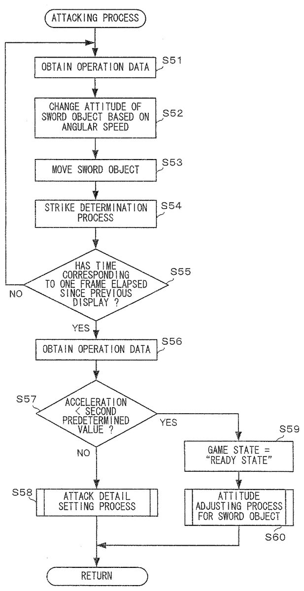
Next, the attacking process of step S12ofFIG. 24will be described.FIG. 27is a flowchart showing the attacking process of step S12in detail. InFIG. 27, initially, the CPU10obtains the operation data126(step S51).
Next, the attitude of the sword object104is changed based on the angular speed data1261included in the operation data126. For example, a rotation matrix indicating the amount of rotation of the attitude is calculated based on the angular speed data1261. Thereafter, the attitude of the sword object104is changed based on the rotation matrix.
Next, the CPU10moves the sword object104based on the moving direction data129and the moving speed data130(step S53). In this example, the moving direction and the speed are determined for each frame. Therefore, in step S53, the sword object104may be moved in an amount corresponding to one frame for each frame, but not for each period during which the attitude is set. Although it is also assumed in this example that even if the attitude is changed, the moving direction and speed are not changed until the speed is set for each frame based on the acceleration in the world coordinate system, the moving direction can be changed every time the attitude is changed even when the moving direction and speed are set for each frame.
Next, the CPU10executes the strike determining process for the sword object104after the sword object104is moved (step S24). This process is similar to that of step S27ofFIG. 25and therefore will not be described in detail.
Next, the CPU10determines whether or not a time corresponding to one frame, i.e., 1/30 sec or 1/60 sec, has elapsed since the display of the previous game screen (the previous process loop) (step S55). If the result of the determination indicates that the time corresponding to one frame has not elapsed (No in step S55), the CPU10goes back to step S51and repeats the process of step S51. Here, as described above, operation data is transmitted from the controller5to the game apparatus3at a rate of once per 1/200 sec. The operation data126is also updated at this rate. Therefore, if the time corresponding to one frame is assumed to be 1/30 sec, the process loop of steps S51to555is executed about six or seven times until the time corresponding to one frame has elapsed.
On the other hand, if the result of the determination in step S55indicates that the time corresponding to one frame has elapsed (YES in step S55), then the CPU10executes a process for resetting the moving direction and the like of the sword object104based on the acceleration at the time. Specifically, the CPU10initially obtains the operation data126(step S56).
Next, the CPU10determines whether or not the magnitude of the acceleration indicated by the acceleration data1262included in the operation data is less than a second predetermined value (step S57). In other words, the CPU10determines whether or not conditions for ending the “attacking state” are satisfied. When the input device8is moved in the “attacking state”, an acceleration is initially applied in a moving direction, and during the end of the motion, an acceleration having a direction opposite to the moving direction is applied so as to stop moving. After the motion is ended, the magnitude of the acceleration becomes small. Therefore, when the magnitude of the acceleration becomes small, the CPU10determines that the motion has been ended. Therefore, the CPU10may determine whether or not the motion has been ended, based on whether or not an acceleration having a small magnitude has been continued for a predetermined period of time. If the result of the determination indicates that the acceleration is not less than the second predetermined value (NO in step S57), the “attacking state” continues, and therefore, the CPU10executes an attack detail setting process (step S58). This process is similar to the process of step S26ofFIG. 25and will not be described in detail. By this process, the moving direction and the strike determination spheres107of the sword object104are set based on an acceleration at that time.
On the other hand, if the result of the determination in step S57indicates that the acceleration is less than the second predetermined value (YES in step S57), the CPU10ends the “attacking state”, and executes a process for going to the “ready state”. Specifically, the CPU10sets data indicating the “ready state” into the game state data131(step S59).
Next, the CPU10executes an attitude adjusting process for adjusting the attitude of the sword object104during the end of an attack (step S60). This is a process for adjusting the attitude of the sword object104during the end of the “attacking state” so as to prevent the attitude of the sword object104from appearing to be unnatural. After the end of this process, the CPU10ends the attacking process.
FIG. 28is a flowchart showing the attitude adjusting process for the sword object104in step S60in detail. InFIG. 28, initially, the CPU10determines whether or not the position of the sword object104falls within the sword movable range (step S71). If the result of the determination indicates that the position of the sword object104does not fall within the sword movable range (NO in step S71), the CPU10changes the position of the sword object104so that it falls within the sword movable range (step S72). Thereafter, the CPU10erases the strike determination spheres107(step S73). On the other hand, if the result of the determination in step S71indicates that the position of the sword object104falls within the sword movable range (YES in step S71), the CPU goes to the process of step S73without executing the process of step S72. Thus, the attitude adjusting process is completed.
The game process of this embodiment has been thus described.
As described above, in this embodiment, when the attitude of the sword object104is controlled based on the angular speed in the “ready state”, then if an acceleration having a predetermined value or more is detected, strike determination spheres for the sword object104are set and the moving direction and the like of the sword object104are determined before the “ready state” is changed to the “attacking state”, so that an attack to the enemy object104or the like is allowed. Thereby, it is possible to provide a game having a novel operability that employs an acceleration sensor and a gyroscopic sensor.
Also, in the “attacking state”, the moving direction and the moving speed of the sword object104are determined based on the acceleration, and the attitude of the sword object104is corrected based on the angular speed. Thereby, the motion of the input device8moved by the player can be more correctly reflected on the attitude and motion of the sword object104.
Note that, in the above-described embodiment, it is determined whether or not the “ready state” is to be switched to the “attacking state”, based on whether or not an acceleration larger than or equal to the first predetermined value has been generated. In this case, it is assumed in this embodiment that only accelerations along two axes, i.e., the x-axis and the y-axis, are used. The present invention is not limited to this. Three accelerations along the x-, y- and z-axes may be used for the determination. For example, as a weapon of the player object101, an “iron sphere”110that can be swung around as shown inFIG. 29is assumed. It is assumed that, as shown inFIG. 30, the player swings around the input device8, and finally moves the input device8toward the front of the player, mimicking the motion of swinging around the “iron sphere”110. When such a swinging motion is performed, an acceleration in the z-axis direction is continuously generated in the input device8. Therefore, when an acceleration in the z-axis direction having a predetermined value or more is continuously detected, it is determined that the iron sphere110is being swung around. Thereafter, if a large change occurs in the acceleration in the z-axis direction (i.e., the input device8is moved toward the front), a strike determination sphere as described above is set for the iron sphere object110in the virtual game space, for example, and the iron sphere object110is moved based on the acceleration, so that the iron sphere object110is used to attack the enemy object104or the like.
Also, in the above-described embodiment, in the attack detail setting process, the number, size and attack power of strike determination spheres107are set, depending on the magnitude of the acceleration. In addition, other processes may be executed, depending on the magnitude of the acceleration. For example, a “sound effect representing sword swinging” may be output from the loudspeaker49of the controller5, depending on the magnitude of the acceleration. Specifically, the “sound effect representing sword swinging” may be set to have a larger sound volume for a larger magnitude of the acceleration. Also, different tones may be used, depending on the magnitude of the acceleration. The controller5can generate a vibration by actuating the vibrator48. Therefore, the controller5may generate a vibration having an intensity depending on the magnitude of the acceleration. Thereby, it is possible to enhance the sense of realism, thereby causing the game to be more enjoyable.
While the invention has been described in detail, the foregoing description is in all aspects illustrative and not restrictive. It is understood that numerous other modifications and variations can be devised without departing from the scope of the invention.
Claims
- A game apparatus comprising: an operation data obtaining unit for obtaining operation data including at least acceleration data and angular speed data from an input device including at least an acceleration sensor and a gyroscopic sensor;a first control unit for controlling at least one of an attitude and a position of a predetermined object in a virtual space based on the angular speed data;a first acceleration condition determining unit for determining whether or not the acceleration data satisfies predetermined conditions when at least one of the attitude and the position of the predetermined object is controlled by the first control unit;a second control unit for causing the predetermined object to start a predetermined motion when the first acceleration condition determining unit determines that the acceleration data satisfies the predetermined conditions, the predetermined motion being a change of motion of the predetermined object from a first game state to a second game state;and an attitude updating unit for updating the attitude of the predetermined object based on the angular speed data when the second control unit moves the predetermined object.
- The game apparatus according to claim 1 , wherein the second control unit causes the predetermined object to start the predetermined motion with reference to at least one of the attitude and the position of the predetermined object when the acceleration data satisfies the predetermined conditions.
- The game apparatus according to claim 1 , wherein the second control unit determines a moving direction of the predetermined object based on the acceleration data when it is determined that the acceleration data satisfies the predetermined conditions, and moves the predetermined object in the determined moving direction.
- The game apparatus according to claim 1 , wherein the first acceleration condition determining unit determines whether or not a magnitude of an acceleration indicated by the acceleration data is larger than a first predetermined value, and when the magnitude of the acceleration indicated by the acceleration data is larger than the first predetermined value, determines that the acceleration data satisfies the predetermined conditions.
- A game apparatus comprising: an operation data obtaining unit for obtaining operation data including at least acceleration data and angular speed data from an input device including at least an acceleration sensor and a gyroscopic sensor;a first control unit for controlling at least one of an attitude and a position of a predetermined object in a virtual space based on the angular speed data;a first acceleration condition determining unit for determining whether or not the acceleration data satisfies predetermined conditions when at least one of the attitude and the position of the predetermined object is controlled by the first control unit;and a second control unit for causing the predetermined object to start a predetermined motion when the first acceleration condition determining unit determines that the acceleration data satisfies the predetermined conditions, the predetermined motion being a change of motion of the predetermined object from a first game state to a second game state, wherein the second control unit includes a strike determination area setting unit for setting a strike determination area for determining whether or not the predetermined object collides with another object, when it is determined that the acceleration data satisfies the predetermined conditions.
- The game apparatus according to claim 5 , wherein the second control unit includes: a second acceleration condition determining unit for determining whether or not the acceleration indicated by the acceleration data is smaller than a second predetermined value after the strike determination area setting unit sets the strike determination area;and a strike determination area erasing unit for erasing the strike determination area when the second acceleration condition determining unit determines that the acceleration is smaller than the second predetermined value.
- The game apparatus according to claim 5 , wherein the strike determination area setting unit sets an effect provided when the strike determination area collides with the other object, based on the acceleration data.
- A non-transitory computer-readable recording medium recording a game program for causing a computer of a game apparatus to execute functionality comprising: obtaining operation data including at least acceleration data and angular speed data from an input device including at least an acceleration sensor and a gyroscopic sensor;controlling at least one of an attitude and a position of a predetermined object in a virtual space based on the angular speed data;determining whether or not the acceleration data satisfies predetermined conditions when at least one of the attitude and the position of the predetermined object is controlled;causing the predetermined object to start a predetermined motion when it is determined that the acceleration data satisfies the predetermined conditions, the predetermined motion being a change of motion of the predetermined object from a first game state to a second game state;and updating the attitude of the predetermined object based on the angular speed data when the predetermined object is moved.
- The non-transitory computer-readable recording medium according to claim 8 , wherein the predetermined object starts the predetermined motion with reference to at least one of the attitude and the position of the predetermined object when the acceleration data satisfies the predetermined conditions.
- The non-transitory computer-readable recording medium according to claim 8 , wherein a moving direction of the predetermined object is determined based on the acceleration data when it is determined that the acceleration data satisfies the predetermined conditions, and the predetermined object is moved in the determined moving direction.
- The non-transitory computer-readable recording medium according to claim 8 , wherein whether or not a magnitude of an acceleration indicated by the acceleration data is larger than a first predetermined value is determined, and when the magnitude of the acceleration indicated by the acceleration data is larger than the first predetermined value, the acceleration data is determined to satisfy the predetermined conditions.
- A non-transitory computer-readable recording medium recording a game program for causing a computer of a game apparatus to execute functionality comprising: obtaining operation data including at least acceleration data and angular speed data from an input device including at least an acceleration sensor and a gyroscopic sensor;controlling at least one of an attitude and a position of a predetermined object in a virtual space based on the angular speed data;determining whether or not the acceleration data satisfies predetermined conditions when at least one of the attitude and the position of the predetermined object is controlled;and causing the predetermined object to start a predetermined motion when it is determined that the acceleration data satisfies the predetermined conditions, the predetermined motion being a change of motion of the predetermined object from a first game state to a second game state, wherein the program causes the computer to further execute functionality comprising setting a strike determination area for determining whether or not the predetermined object collides with another object, when it is determined that the acceleration data satisfies the predetermined conditions.
- The non-transitory computer-readable recording medium according to claim 12 , wherein the program causes the computer to further execute: determining whether or not the acceleration indicated by the acceleration data is smaller than a second predetermined value after the strike determination area is set;and erasing the strike determination area when it is determined that the acceleration is smaller than the second predetermined value.
- The non-transitory computer-readable recording medium according to claim 12 , wherein an effect provided when the strike determination area collides with the other object is set based on the acceleration data.
Disclaimer: Data collected from the USPTO and may be malformed, incomplete, and/or otherwise inaccurate.