U.S. Pat. No. 8,298,845
MOTION PLATFORM VIDEO GAME RACING AND FLIGHT SIMULATOR
Issue DateDecember 23, 2008
Illustrative Figure
Abstract
A motion platform configured as automobile racing vehicle simulator is disclosed. The apparatus that embodies the geometry and various methods of articulation related to a motion platform having advantageous geometric relationships are also set forth. In one embodiment enhanced performance of a motion-generating device having a rider or driver is accomplished through the location of the center of mass of a payload as near as practicable to the pivotal center of the payload support. The device has a base supporting an upstanding column and a sled pivotally mounted to the top of the column. The rider is accommodated on the sled. To achieve the event simulated results intended various acts are performed in configuring the motion platform. These include locating a pivotal center of motion on a column in a position above the base of the motion generating device; locating the position of a center of mass, the center of mass calculated from the mass of the sled and the mass of a rider accommodated on the sled; and mounting the sled on the pivotal center of motion of the device such that the located center of mass is close to the pivotal center of motion of the motion platform.
Description
Elements in the figures are illustrated for simplicity and have not necessarily been rendered according to any particular sequence or embodiment. DETAILED DESCRIPTION OF THE INVENTION In the following description, and for the purposes of explanation, numerous specific details are set forth in order to provide a thorough understanding of the various aspects of the invention. It will be understood, however, by those skilled in the relevant arts, that the present invention may be practiced without these specific details. In other instances, known structures and devices are shown or discussed more generally in order to avoid obscuring the invention. In many cases, a description of the operation is sufficient to enable one to implement the various forms of the invention, particularly when the operation is to be implemented in software. It should be noted that there are many different and alternative configurations, devices and technologies to which the disclosed inventions may be applied. The full scope of the inventions is not limited to the examples that are described below. The following description is directed to a race car simulation motion platform. Those skilled in the art will appreciate that the description of the race car simulation is readily adaptable to other simulation scenarios, such as, but not limited to, those described above. In the invention, as shown inFIG. 1and the subsequent figures, a motion platform, generally10, is provided. The motion platform10may be used for providing relative motion between a base generally12and a sled, generally14. The sled14is mounted for angular displacement relative to the base12. That is, the sled generally14is pivotally supported on the base, generally12through a universal joint mounting connection. The universal joint may be, but is not limited to, a “cross-type” universal joint having two yokes and a “cross.” Similar apparatus may include a ball-and-socket type connection, or any ...
Elements in the figures are illustrated for simplicity and have not necessarily been rendered according to any particular sequence or embodiment.
DETAILED DESCRIPTION OF THE INVENTION
In the following description, and for the purposes of explanation, numerous specific details are set forth in order to provide a thorough understanding of the various aspects of the invention. It will be understood, however, by those skilled in the relevant arts, that the present invention may be practiced without these specific details. In other instances, known structures and devices are shown or discussed more generally in order to avoid obscuring the invention. In many cases, a description of the operation is sufficient to enable one to implement the various forms of the invention, particularly when the operation is to be implemented in software. It should be noted that there are many different and alternative configurations, devices and technologies to which the disclosed inventions may be applied. The full scope of the inventions is not limited to the examples that are described below.
The following description is directed to a race car simulation motion platform. Those skilled in the art will appreciate that the description of the race car simulation is readily adaptable to other simulation scenarios, such as, but not limited to, those described above.
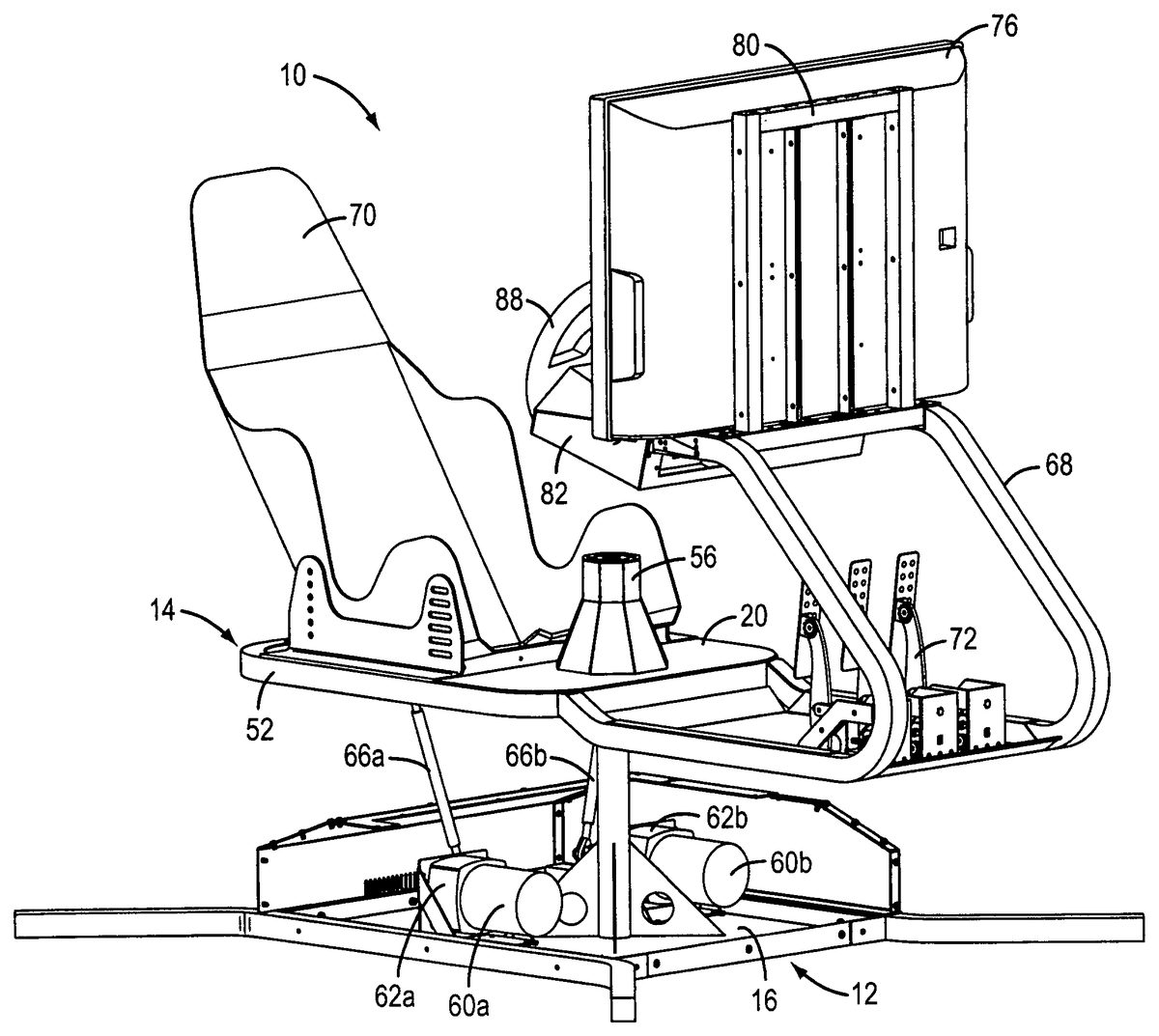
In the invention, as shown inFIG. 1and the subsequent figures, a motion platform, generally10, is provided. The motion platform10may be used for providing relative motion between a base generally12and a sled, generally14. The sled14is mounted for angular displacement relative to the base12. That is, the sled generally14is pivotally supported on the base, generally12through a universal joint mounting connection. The universal joint may be, but is not limited to, a “cross-type” universal joint having two yokes and a “cross.” Similar apparatus may include a ball-and-socket type connection, or any other type of rotary joint, or the like, that provides and allows pitch and roll motion.
A portion of the motion platform10, that is the base12, and one form of the deck20(FIG. 3) of the sled14, is shown inFIGS. 1 through 4. In these figures the base12is a support structure having a floor16presenting a generally rectangular footprint. The base of the motion platform may have longitudinally directed side elements, generally configured as a straight middle section having end portions extending outwardly from the floor portion16of the base. The longitudinally directed side elements provide elements acting as forward facing outriggers such as24aand24band rearward facing outriggers such as44aand44b. (FIG. 2) These extended portions of the longitudinally directed side elements are positioned to provide increased stability to the device. The forward facing outriggers24aand24bwill extend forward and outwardly in one embodiment of the invention while the rearward facing outriggers44aand44bextend rearward and outwardly in one embodiment of the invention. Retention fasteners, such as, but not limited to bolts26, are used to attach the longitudinally directed side members to the rest of the base structure. The base12will be supported on a floor surface, the ground, or other support surface.
The base may be equipped with an upstanding edge30around the periphery of the floor16of the base. The edge need not be a continuous edge but can have gaps.
A pillar34is supported on and affixed to the floor16of the base. The pillar34may be mounted on the longitudinal centerline of the base12as shown, but could be mounted off the centerline in certain situations. The pillar34is supported by gussets, three of the four gussets in this embodiment shown as36a-cinFIG. 2, with these gussets being attached to the floor of the base.
The upper end42of the pillar34will support a first yoke40of a roller bearing universal joint. The first yoke40will be fixedly attached to the top or upper end of the pillar34such that a line through the bearing retainers of the first yoke will be transverse to the longitudinal centerline of the base12. The first yoke40is fixedly attached to the pillar34so that the yoke40does not move relative to the pillar. In another form of the invention, a yoke similar to yoke40can be rotatably carried on the pillar34.
FIG. 3is a view of a portion of the deck20of the sled without all of the elements of the sled installed on the deck. In this figure a perimeter frame52includes a first floor plate54that is attached to the perimeter frame52. The first floor plate54is mounted in a zone at one end of deck and this first floor plate comprises less then the entire length of the deck defined by the perimeter frame52. The first floor plate54will have a large through aperture formed in it. The aperture is not visible in this view. A stanchion56, a hollow body having an open bottom and top that can be closed off, will be located and fixedly fastened over the aperture in the deck so that the interior of the stanchion is accessible through the aperture in the floor plate. A second floor plate will be fastened to the forward zone of the end of the deck not occupied by the first floor plate.
Two true axis of rotation or degrees of freedom; one being roll—the rotation about the longitudinal axis of the sled; and the second being pitch—rotation about the transverse axis of the sled; are two of the five degrees of freedom provided by the mechanism of the invention. In addition to roll and pitch, three other degrees of freedom, namely: heave, sway and surge, are simulated in the device presented herein.
As stated above, the hollow body stanchion56, is supported over an aperture formed in the first floor plate54. The stanchion may be welded or otherwise fastened, such as by, but not limited to, bolting, screwing, adhesively fastening, or the like, to the floor plate or other support structure, over the aperture in the first floor plate. This stanchion56, which may be, but is not limited to, an octagonal structure, open at the bottom, is in the general shape of a cone. One embodiment is a cone with an octagonal cylinder at the upper area of the stanchion as shown in various figures provided herewith. In another embodiment the cylinder can be smooth or multi-sided. The stanchion has multiple sides, in one case as shown, there are eight sides, each a trapezoid or other shape, however the number of sides or the shape of the stanchion may be of one of many configurations, such as but not limited to, a three-sided structure or more than three-sided structure, or a structure having a curved side wall configuration with a single curved sidewall or a curved sidewall of more than a single curved sidewall. The eight-sided stanchion shape may be less expensive to manufacture than a single curved sidewall cone shape and thus it is shown in the figures. A true cone having an open bottom and truncated and covered upper end could also be used in an embodiment of the device. Also, the base of the stanchion or cone need not be symmetrical or have a constant radius but may have an oblong or other designer dictated shape that would allow the sled to move a longer distance in one direction than in another direction before interference between the pillar and the opening edge of the stanchion or cone. Another embodiment of the invention is a vertical rectangle, instead of a cone shape, for the stanchion.
The stanchion56will have a closed top in one iteration of the invention. An open top stanchion is an alternative embodiment however a closed top has the advantage, in some circumstances, of preventing unfettered access to the inside of the stanchion from its top.
FIG. 4shows the partially completed deck of the sled20mounted in position on the pillar34that is supported on the floor of the base16. The connection between the top of the pillar34and the stanchion56is made through a universal joint with one yoke, the first yoke identified as40above, mounted on the top of the pillar and transverse to the longitudinal centerline of the base12. The second yoke and the cross of the universal joint, neither visible in any of the drawings but the structure and the operation of these portions of a conventional universal joint are well known to persons having skill in the art. An alternative embodiment is shown inFIG. 5as item98. This alternative embodiment is mounted to the inside of the stanchion56at the upper portion of the stanchion. Returning to the embodiment ofFIG. 4, the second yoke of the universal joint is mounted such that a line through its bearing supports is transverse to the installed position of the first yoke40of the universal joint. The mounting directions of the first and the second yokes could each be rotated ninety degrees, or any other number of degrees in alternative embodiments, and the intended operation of the universal joint in this embodiment would not be affected. This universal joint mounting and positioning arrangement allows the deck20of the sled to pivot, but, in one embodiment, not rotate, on the pillar34forwardly, rearward, sideways and all points in-between. In one embodiment, with the universal joint fixedly mounded to the top of the pillar34and fixedly mounted to the top interior portion of the stanchion56, there will be no yaw motion between the deck of the sled and the base12of the motion platform.
Returning toFIG. 1various mounted elements of the motion platform are seen. Starting from the base, generally12, a first motor60aand a second motor60bare mounted to the floor16of the base. These motors, which could be fractional motors, may be DC brush type motors, DC brushless motors, AC motors, stepper motors, or the like. The motors60aand60b, in one version of the invention may have gearhead reducers62aand62bthat will receive rotary input from the output of the motors60aand60b.
The applicant believes that a combination motor and gearhead unit, such as a Nord ¼ Horsepower Gearhead AC motor, is a good choice for use in its motion platform as such motor-gearhead is compact, light weight, durable and may be less expensive than other motor and gearhead options. Each gearhead reducer output shaft will be coupled to a pitman arm such as those shown as64aand64binFIG. 5. A second set of links, connecting rods66aand66b(FIG. 1, et al.), have a first end attached to the first set of pitman arms64aand64b, in one embodiment using ball joint rod end fittings at the attachment point, and the second end of each of the connecting rods66aand66bare attached, also through a ball joint rod end to the sled14, and more definitively, to brackets mounted on the bottom surface of the first floor plate54. In one embodiment of the invention these brackets may be hingedly mounted.
The motion platform will, in one version but not in every version, be compatible with U.S. residential voltage systems so that the motion platform can be plugged into home electrical distribution systems. Conventional three-prong plug and wiring elements will be associated with the motion platform to supply operating power to the unit. The wiring will connect to a junction box on the unit for distribution to various controllers, monitors, computers, and other systems as appropriate.
The sled, generally14inFIG. 1, is the support platform for a seat, such as the competition or racing seat70, available from Corbeau Industries as well as many other racing seat suppliers, including a competition seat belt set, a pedal assembly72, one model of pedal assembly available from Ball Racing Developments, Ltd. such as Model Speed7, which may include an accelerator pedal, a brake pedal, a clutch pedal and a dead pedal.
Another vendor of steering wheels and pedal sets is Happ Controls, Inc.
A support structure including monitor support frame68which includes upwardly extending towers and angled legs supports a monitor76, a control console, a dashboard and a steering wheel, among other components, such as but not limited to, a shifter, either shifter paddles or a conventional shift lever, a ventilation port, a camera facing the driver or the instruments on the console, or game control operator interfaces on the perimeter52of the deck of the sled. The monitor76may also include or be a video input module that will generate an image on the monitor, in this case a liquid crystal display, and appropriate drivers.
A driver input device, here a force feedback steering wheel88, is also supported on the monitor support frame68. A steering wheel of the type supplied by Logitech, such as Model G25 Racing Wheel is one option for an appropriate steering wheel. A set of monitors and controls, such as those as would be found in a race car or on an aircraft, such as, but not limited to, a gear shift lever, a tachometer, an oil pressure gauge, a water temperature gauge, a speedometer, a transmission status indicator and any other gauge, warning light, recording device, such as a GPS system or target acquisition screen, or other apparatus as is found in a race car, truck, airplane and the like. An adjustable rack82, having one or more locking bolts84, will provide adjustability, fore and aft, to the steering wheel88and other components that can be adjusted to accommodate drivers of different arm or body dimensions.
A safety switch, for the purpose of stopping motion of the motion platform, may be one of the controls carried on the dashboard with the other monitors and controls.
FIG. 5is a simplified representation of the actuation devices of the motion platform. In this mock up or model the motors60aand60bare shown and the pitman arms64aand64bare clear. The pitman arms each have one end of the pitman arm mounted to one each of the output shafts of the gearhead reducers. These pitman arms64aand64bare parked in a neutral position such that the deck surface or first floor plate54is level and the cone56is substantially vertical, extend generally horizontally toward the centerline of the base on which the pillar34is mounted. Ball joint rod end connectors78aand78bare connected to second ends of the two pitman arm64aand64b. These rod ends78aand78bare also connected to lower ends of connecting rods66aand66b. These connecting rods66aand66bare therefore connected between the second ends of the pitman arm and mounting locations on the bottom of the first floor plate54. Universal joint type rod ends can be used as an alternative to the ball joint rod ends.
Each of the pitman arms has its free end, the end that is not attached to the output shaft of each of the gear head reducers, pointing inwardly toward each other at a shallow angle below horizontal. If both of the pitman arms were pointing straight up they would, for purposes of this description, each be at zero degrees of rotational displacement. If each of the pitman arms were pointing straight down they each would be at one hundred-eighty degrees of rotational displacement. In one embodiment of the invention the pitman arms will be limited in rotational displacement to an arc of less than one hundred eighty degrees. For example, for the right side pitman arm64athe rotational displacement may extend from about twenty degrees to about one hundred fifty-five degrees. For the left side pitman arm64bthe rotational displacement may be from about three hundred thirty-five degrees to about two hundred five degrees.
Limiting the range of the pitman arms to a rotational displacement of less than one hundred eighty degrees is one embodiment of the invention. This limitation may be broadened in other embodiments. For instance, it is contemplated by the inventor that it may be preferential to allow three hundred sixty degree rotation of the pitman arms attached to the gear head drives. By allowing such full rotational freedom of each arm, independent of the other arm, the gear head drives will be protected from damage due to interfering rotations between the drives. That is, since each drive is capable of three hundred sixty degrees of rotation by design, regardless of the position of the other gearhead drive, there will be no reasonable possibility of interference between the gearhead drives and the associated motors that would be detrimental to the drives or motors.
In operation, numerous payload displacement motions are possible with the simple configuration shown inFIG. 5. For instance, if the motor60adrives the gearhead reducer62asuch that the pitman arm64ais moved from the somewhat below horizontal position shown to a position where the pitman arm64ais at twenty-five degrees and above the horizontal plane while at the same time motor60bdrives the gearhead reducer62bsuch that the pitman arm64bis moved from the somewhat below horizontal position shown to a position where the pitman arm64bis at two hundred five degrees and below the horizontal plane the floor plate54, representative of the entire sled, the sled will pivot on the universal joint98at the top of the pillar34toward the operator's left. The plate54will tilt along the major axis of the sled, in this case to the left.
When both pitman arms64aand64bare rotated upwardly to the same ending point, for instance, twenty five degrees for the right side pitman arm64aand three hundred and thirty five degrees for the left side pitman arm64b, the plate54will tilt transverse to the major axis of the sled on the universal joint98so that the front of the sled will rise. This motion is true pitch. Likewise, when both pitman arms64aand64bare rotated downwardly simultaneously the same amount the plate54will tilt in the plane of the minor axis of the sled on the universal joint98but this time the front of the sled will dip and the rear of the sled will rise. This is also true pitch. If however both pitman arms64aand64bare rotated simultaneously but at different rates and rotational angles the plate54will tilt in a direction or displacement partially transverse to the major axis of the sled and partially in the major axis of the sled on the universal joint98depending on the relative motion, speed and angular displacement of the pitman arms relative to each other. This allows a point on the plate54, representative of a point on the sled, to move on an arc from horizontal in two axes, namely in roll and in pitch. By the speed and direction of the pitman arm movement heave, sway and surge can be simulated. Heave is generally movement up and down. Moving left and/or right is sway. Surge is movement forward and backward. In this invention heave, sway and surge can each be, and are, simulated.
InFIG. 6a torus is shown superimposed over the cone of the device shown inFIG. 5. This torus represents the distribution of the mass of the payload around the pivotal center represented by the center of the universal joint mounted at the top of the pillar and to the upper inside location of the stanchion. The area described by the torus represents the mass distribution of the payload relative to the pivotal center at the top of the pillar. This figure shows that the mass of the payload is equally distributed around the pivotal center of the device. Thus for any displacement of the payload the mass that needs to be moved is balanced by an equal mass on the opposite side of the pivotal center. In operation it is desirable to minimize the distance from the center of mass to the pivotal center of the device. As this distance is minimized the torus will become smaller in horizontal diameter as well as in the vertical diameter. At the outer surface of the torus the balanced mass is at its furthest distance from the pivotal center but it is counterbalanced by an equal mass one hundred and eighty degrees away from the first mass. In this situation the force needed to move the payload on the pivotal center is minimized as the equal distribution of the mass means that the opposed mass will be added to the horsepower delivered by the gearhead motors to move the payload. It should also be noted that as the center of mass moves toward the interior of the torus the torus will become smaller which represents that the force needed to move the payload will decrease.
There will be a processor associated with the motion platform. In one embodiment of the invention the processor will be a dedicated microprocessor controller associated with the motion platform. In another version the processor could be a desktop, laptop, or other packaged processor that can be associated with the motion platform and connected thereto by hardwire or wireless communication options. The processor will include a controller that will control the output or response of the motors and the gear heads to move the deck on the universal joint responsive to inputs from software running the simulated game. Software, some that is currently available in the consumer market, is augmented and interfaced using software that is unique to the control of the motion platform presented here. Electronically integrated visual displays, projected or presented on at least one high resolution monitor, and sound presentation systems, such as, but not limited to speakers mounted in the vicinity of the motion platform, seat mounted head phones or helmet housed speakers, or the like will be used in conjunction with the motion of the sled to add to the simulated reality of the motion platform. Sound delivery to the operator is accomplished using THX surround sound or other sound delivery schemes of similar high performance capability.
A plurality of sensors such as, but not limited to, shaft encoders or linear encoders, may be associated with the motion platform. There may be shaft encoders associated with the motor, the output shaft of the gearhead reducer, and/or linear recorders associated with the pitman arm links, or with the sled to sense its position and to provide other input information to the controller associated with the motion platform and its controls.
A safety switch may be associated with the base of the motion platform. This safety switch would be responsive to the base of the platform not being in proper engagement with the supporting floor under the motion platform.
FIGS. 7,8and9are pictorial representations of a motion platform generally10, with an operator100, in this case a person driving a racecar simulator, sitting in the seat70. These three figures show three representative positions of the payload, that being the sled and the operator taken together, on and relative to the base generally12. In each of these figures a center of mass, labeled in the figures as “CM,” is shown in different locations in each of the three figures. The CM is calculated by finding the center of mass of the payload, that being the sled and an operator seated in the seat70. This calculated CM may be above the pivot point, at the same level as the pivot point, or below the pivot point, but in this invention, the CM is intended to be as close to the pivot point as possible as the payload is moved through various degrees of freedom afforded by the associated linkage and the linkage deployment between the pitman arm links and the bottom of the sled.
In a preferred embodiment, as shown inFIGS. 7-9, the tipping of the sled and the driver or rider forward, rearward or to either side, or in a combination of these directions will cause the rider or driver to experience the feeling of acceleration, deceleration and centrifugal forces. The tipping of the sled will cause this sensation of acceleration, deceleration or centrifugal force due to gravitational forces acting on the rider or driver as the sled is tipped forward, backward or to the side, or any combination of displacements of the sled and driver from horizontal.
InFIG. 7the sled, generally14, is in full pitch pose with the front of the sled near maximum elevation. Each of the pitman arms, such as the one shown as64bwill be below horizontal. In quickly getting to this pose the driver will sense acceleration. It should be noted that in most situations, where the driver is concentrating on the game and all the action is being displayed on the monitor, the driver's eye location will be looking at the monitor76and the relative distance between the driver's eye and the monitor will be substantially constant. In this figure the center of mass CM, is located aft of the pivotal center CP of the sled on the universal joint. Both the center of mass, CM, and the pivotal center, CP, are close and this is desirable as the energy needed to move the payload to the next pose, such as is shown inFIG. 7, is relatively small as there are no long force vectors to overcome in moving from one pose to another.
InFIG. 8the payload, generally14, is in full pitch pose with the front of the sled near minimum elevation. Each of the pitman arms, such as the one shown as64bwill be above horizontal. In quickly getting to this pose the operator will sense deceleration. In this figure the center of mass CM is located fore of the pivotal center CP of the payload. Both centers, the CM and CP, are close to each other. This, as above, is similarly beneficial as the energy needed to move the payload to the next pose is relatively small as there are no long force vectors to overcome.
InFIG. 9the payload, including the rider or driver, generally14, is in full roll pose with the payload near maximum starboard roll. One of the pitman arms, pitman arm64awill be displaced at or below the horizontal plane (observed from the front of the sled as shown) and the other pitman arm64bwill be displaced at or above the horizontal plane depending on the position of the other pitman arm64a. In quickly getting to this pose the operator will sense centrifugal or g-forces sensed in a sharp turn.
As stated above, the sense of the centrifugal force is due to the gravitational force on the rider. The rider or driver will experience the tipping of the sled by his sense of gravitational forces acting on his or her body as the sled is tipped but she/he will feel the gravitational force as centrifugal force as if the racecar is going through a turn. This is also the case with the tipping of the sled downwardly in the front (FIG. 8) to simulate deceleration or rearwardly where the sled is down in the rear as shown inFIG. 7, to simulate acceleration.
Returning toFIG. 9, in this figure the center of mass CM is located starboard of the pivotal center CP of the payload. As in the two poses described above both centers, the CM and CP, are close to each other. Here also, the energy needed to move the payload to the next pose is relatively small as there are no long force vectors to overcome.
While the invention is described herein in terms of preferred embodiments and generally associated methods, the inventor contemplates that alterations and permutations of the preferred embodiments and methods will become apparent to those skilled in the art upon a reading of the specification and a study of the drawings. For instance, a pair of one-piece linear ball screw gear drive with six inches of travel could be used in place of the gearhead, pitman arm and connecting rod. This is a higher cost alternative to the embodiment set forth above.
Accordingly, neither the above description of preferred exemplary embodiments nor the abstract defines or constrains the invention. Rather, the issued claims variously define the invention. Each variation of the invention is limited only by the recited limitations of its respective claim, and equivalents thereof, without limitation by other terms not present in the claim.
Claims
- A method of enhancing performance of a motion-generating device accommodating an occupant, the device having a base, an upstanding column and a sled, the occupant accommodated on the sled, the method comprising the acts of: locating a pivotal center of motion on the upstanding column in a position above the base of the motion generating device;locating the position of a center of mass, the center of mass calculated from the mass of the sled and the mass of an exemplar occupant accommodated on the sled;mounting the sled on the pivotal center of motion such that the located center of mass is proximate the pivotal center of motion of the motion generating device;providing a prime mover to impart motion to the sled, the prime mover connected to the sled through linkage.
- The method set forth in claim 1 further comprising the acts of: positioning a pivotable joint on the column to locate the pivotal center of motion;mounting the sled to the pivotable joint such that the center of mass is proximate the pivotable center of motion.
- The method set forth in claim 1 wherein mounting the platform on the pivotal center of motion such that the located center of mass is proximate the pivotal center of the motion generating device further comprises the act of: minimizing force necessary to impart motion to the sled and the occupant, the combined mass of the sled and the occupant comprising a payload, by minimizing the proximate distance between the center of mass of the payload and the pivotal center of motion.
- The method set forth in claim 1 further comprising the act of: providing a stanchion on the sled, the stanchion providing a mounting location for attachment of the upstanding column to the interior of the stanchion through the pivotal joint whereby locating the center of mass proximate the pivotal center of motion is realized.
- The method set forth in claim 4 wherein the stanchion is positioned over the upstanding column and the pivotal center of motion is located inside the stanchion.
- The method set forth in claim 1 further comprising the act of: minimizing the force necessary to impart motion to a sled and an occupant of the sled, the combination of the sled and the occupant of the sled comprising a payload;enabling the act of locating the center of mass of the payload proximate the pivotal center of motion by mounting the sled on the pivotal center of motion such that the located center of mass of the payload is proximate the pivotal center of motion of the motion generating device.
- A motion platform having two true degrees of freedom, the motion platform comprising: a base;a pillar, having an upper end, the pillar fixedly mounted to and extending from the base;a universal joint pivotally attached to the upper end of the pillar;a sled having a deck surface, the deck surface including an aperture;a stanchion, having an upper portion, the stanchion mounted to the deck surface of sled, the stanchion covering at least a portion of the aperture in the deck surface and extending above the deck surface of the sled;the universal joint, pivotally attached to the upper end of the pillar, is further attached to the upper portion of the stanchion.
- The motion platform in accordance with claim 7 wherein the universal joint comprises a universal joint cross element having a center, the center of the universal joint cross element defining a pivot center.
- The motion platform in accordance with claim 8 wherein the payload has a center of mass, the center of mass of the payload vertically aligned with the pivot center.
- The motion platform in accordance with claim 9 wherein the center of mass of the payload is proximate the pivot center of the payload in all angular displacements of the payload relative to the base of the motion platform.
- The motion platform in accordance with claim 10 wherein the center of mass of the payload is located within the wall of a virtual cone having its tip coinciding with the pivot center, the cone major axis aligned with the major axis of the pillar.
- The motion platform in accordance with claim 11 the virtual cone having a sixty-degree angle between the major axis of the virtual cone and the wall of the virtual cone.
- The motion platform in accordance with claim 10 wherein the stanchion has base and a top and the height of the stanchion from the base to the top is between five and fifteen inches.
- The motion platform in accordance with claim 13 wherein the universal joint is mounted in the upper portion of the stanchion such that the pivot center defined by the center of the cross of the universal joint is within two inches from the top of the stanchion.
- The motion platform in accordance with claim 9 wherein the sled element of the payload contacts only the universal joint when the motion platform is unpowered and stationary.
- A motion platform comprising;an upwardly extending pillar having an upper end;a universal joint attached to the upwardly extending pillar;a stanchion mounted to the universal joint attached to the pillar;a sled having a deck surface, the stanchion mounted to the sled and the stanchion extending above the deck surface of the sled.
- The motion platform in accordance with claim 16 further comprising: a base, the pillar attached to the base.
- The motion platform in accordance with claim 17 wherein the stanchion comprises a multi-sided structure having an open bottom portion, the stanchion carried on the pillar with the open end of the stanchion surrounding the pillar.
- The motion platform in accordance with claim 18 wherein the stanchion is a hollow polyhedron.
- The motion platform in accordance with claim 19 wherein the hollow polyhedron has eight sides, a closed top and an open bottom.
- A method of supporting a payload on a motion platform, the motion platform having a base, the method comprising the acts of: providing an upwardly extending pillar extending from the base;providing a universal joint on the pillar;attaching the pillar to the interior of a stanchion carried on the payload, the attachment comprising attaching the universal joint to the stanchion.
- A motion platform comprising a sled having a deck and a base having a pillar, the method of supporting the sled portion of the motion platform on the pillar of the base comprising the acts of: attaching a hollow polyhedron to the deck of the sled portion of the motion platform with the polyhedron extending above the deck;attaching the pillar of the base to the polyhedron at a point of the polyhedron vertically above the deck;whereby the sled of the motion platform is supported on the pillar of the base.
- A method of enhancing performance of a motion-generating device, the device having a base, an upstanding column carried on the base and a sled supported on the column, the sled for accommodating an occupant, the method of enhancing the performance of the motion-generating device comprising the acts of: locating a pivotal center of motion of the sled on the column above the base of the motion generating device;calculating the center of mass from the mass of the sled and the mass of an exemplar occupant accommodated on the sled;locating the position of the calculated center of mass;mounting the sled at the pivotal center of motion on the column such that the center of mass of the combined sled and exemplar occupant is within a one inch radius from the pivotal center of motion of the motion generating device.
Disclaimer: Data collected from the USPTO and may be malformed, incomplete, and/or otherwise inaccurate.