U.S. Pat. No. 8,115,588
OPERATING DEVICE AND GAME CONTROLLER
AssigneeALPS Electric Co., Ltd.; Sony Computer Entertainment, Inc.
Issue DateApril 27, 2007
Illustrative Figure
Abstract
A novel game controller is provided. The game controller includes: a lower operation button supported by a rotation shaft so as to be capable of a rotating operation; a resistor arranged on an internal substrate; and a conductive member to be pressed against the resistor by a rotating operation on the lower operation button, the conductive member having elasticity. The resistor outputs an analog signal in accordance with a contact area of the conductive member, thereby realizing an analog input.
Description
DETAILED DESCRIPTION OF THE INVENTION The invention will now be described by reference to the preferred embodiments. This does not intend to limit the scope of the present invention, but to exemplify the invention. FIG. 1shows the use environment of a game system according to an embodiment of the present invention. The game system1includes an image display apparatus3, a sound output apparatus4, a game apparatus10, and a controller20. The image display apparatus3, the sound output apparatus4, and the controller20are connected to the game apparatus10. The controller20is an operating device from which a user makes operation inputs. The game apparatus is a processing unit which processes a game application based on the operation inputs from the controller20, and generates image signals showing the results of processing of the game application. The image display apparatus3is a display for outputting image signals. It receives the image signals generated by the game apparatus10, and displays a game screen. The sound output apparatus4consists of speakers for outputting sound. It receives sound signals generated by the game apparatus10, and outputs game sound. The image display apparatus3and the sound output apparatus4constitute an output apparatus of the game system1. The game apparatus10and the image display apparatus3may be connected by either wired means or wireless means. The game apparatus10and the image display apparatus3may be connected with AV cables. Alternatively, a home network using network (LAN) cables or a wireless LAN may be constructed between the game apparatus10and the image display apparatus3. The controller20has the function of transmitting user's operation inputs to the game apparatus10. In the present embodiment, it is configured as a wireless controller which is capable of wireless communication with the game apparatus10. The controller20and the game apparatus10may establish wireless communication therebetween using Bluetooth™ protocol. The game apparatus10can hold wireless communications with a plurality of controllers20. In ...
DETAILED DESCRIPTION OF THE INVENTION
The invention will now be described by reference to the preferred embodiments. This does not intend to limit the scope of the present invention, but to exemplify the invention.
FIG. 1shows the use environment of a game system according to an embodiment of the present invention. The game system1includes an image display apparatus3, a sound output apparatus4, a game apparatus10, and a controller20. The image display apparatus3, the sound output apparatus4, and the controller20are connected to the game apparatus10.
The controller20is an operating device from which a user makes operation inputs. The game apparatus is a processing unit which processes a game application based on the operation inputs from the controller20, and generates image signals showing the results of processing of the game application.
The image display apparatus3is a display for outputting image signals. It receives the image signals generated by the game apparatus10, and displays a game screen. The sound output apparatus4consists of speakers for outputting sound. It receives sound signals generated by the game apparatus10, and outputs game sound. The image display apparatus3and the sound output apparatus4constitute an output apparatus of the game system1.
The game apparatus10and the image display apparatus3may be connected by either wired means or wireless means. The game apparatus10and the image display apparatus3may be connected with AV cables. Alternatively, a home network using network (LAN) cables or a wireless LAN may be constructed between the game apparatus10and the image display apparatus3.
The controller20has the function of transmitting user's operation inputs to the game apparatus10. In the present embodiment, it is configured as a wireless controller which is capable of wireless communication with the game apparatus10. The controller20and the game apparatus10may establish wireless communication therebetween using Bluetooth™ protocol. The game apparatus10can hold wireless communications with a plurality of controllers20. In other words, the game system1can realize one-to-N connection between the game apparatus10and controllers20. The game apparatus10functions as a master unit. The controller20functions as a slave unit. It should be appreciated that the controller20is not limited to a wireless controller, but may be a wired controller which is connected to the game apparatus10through a cable.
The controller20is driven by a not-shown battery, and includes a plurality of buttons and keys for making operation inputs for game progress. When the user operates the buttons and keys on the controller20, the operation inputs are transmitted to the game apparatus10wirelessly. The game apparatus10receives the operation inputs pertaining to the game application from the controller20, controls the progress of the game according to those operation inputs, and generates game image signals and game sound signals. The game image signals and game sound signals generated are output from the image display apparatus3and the sound output apparatus4, respectively. The game apparatus10also has the function of transmitting a vibration control signal to the controller20to cause the controller20to vibrate depending on the progress of the game application. The controller20contains a vibrator, and makes the vibrator vibrate when it receives the vibration control signal.
FIG. 2shows the appearance and configuration of the controller. The controller20has an arrow key21, analog sticks27, and four types of operation buttons26. The arrow key21, the analog sticks27, and the operation buttons26constitute an input unit which is arranged on the case top30. The four types of buttons22to25are marked with different symbols in different colors in order to distinguish them from each other. More specifically, the ∘ button22is marked with a red circle, the x button23a blue cross, the □ button24a purple square, and the Δ button25a green triangle. The rear29of the case of the controller20is provided with a plurality of LEDs.
The user holds a left grip28bwith the left hand and a right grip28awith the right hand when operating the controller20. The arrow key21, the analog sticks27, and the operation buttons26are arranged on the case top30so that they can be operated by the user who is holding the left grip28band the right grip28a.
An LED button31is also provided on the case top30. The LED button31is used, for example, to display a menu screen on the image display apparatus3. It also has the functions of notifying the user of incoming mails, and indicating the battery level and other status of the controller20by modifying the lighting status of the LED. For example, the LED is lit in red during charging, lit in green when fully charged, and blinks in red when the battery level is low.
FIG. 3shows the appearance and configuration of the controller according to the embodiment when viewed from the rear side. The back29of the case of the controller20is provided with a plurality of LEDs. When viewed from the case rear, the arrow key21is located to the right and the operation buttons26are to the left on the case top. The two analog sticks27are arranged between the arrow key21and the operation buttons26.
The controller20of the embodiment has a first LED210a, a second LED210b, a third LED210c, and a fourth LED210d, which are arranged in a horizontal row in an upper right area of the case rear29with respect to the longitudinal center. Hereinafter, the first LED210a, the second LED210b, the third LED210c, and the fourth LED210dwill be written as “LEDs210” or when referred to collectively. Numerals are inscribed or printed near the LEDs210. For example, the LEDs210are used for indicating a controller number which is connected with a game character. A USB connector46is provided in the center of the case rear29. A USB cable extended from the game apparatus10can be plugged into the USB connector46for the purpose of charge processing on the controller20. It should be appreciated that the controller20, when connected with the USB cable, may be used as a wired controller.
An upper operation button220a, an upper operation button220b, a lower operation button230a, and a lower operation button230bare provided on the case rear29at horizontally symmetrical positions in the longitudinal direction of the case rear. The upper operation button220aand the upper operation button220bare positioned so that they are operated with the tips of the forefingers of the right hand and the left hand, respectively, when the user holds the right grip28aand the left grip28b. The lower operation button230aand the lower operation button230bare positioned so that they are operated with the tips of the middle fingers of the right hand and the left hand, respectively. This prevents the LEDs210from being covered by the forefingers or middle fingers when the user operates the upper operation button220a, the upper operation button220b, the lower operation button230a, and the lower operation button230b.
In the controller20of the embodiment, the upper operation button220aand the upper operation button220bare configured as push buttons. Inputs from the upper operation buttons220are made by depressing them, which allows analog inputs according to the amounts of depression. The upper operation buttons220are urged outwardly from the case by rubber or other elastic bodies. Consequently, when not depressed by a user, the upper operation buttons220are urged away from the case and remain at extended positions.
The lower operation button230aand the lower operation button230bare formed as trigger buttons which are supported rotatably. The lower operation buttons230are rotatable input interfaces, and allow analog inputs according to the amounts of rotation. The lower operation buttons230are rotatably supported by rotation shafts, and are urged outwardly from the case by rubber or other elastic bodies or by spring members. As a result, when not depressed by the user, the lower operation buttons230are urged away from the case and remain at extended positions.
The lower operation buttons230are rotatably supported by the rotation shafts which are situated substantially in parallel with the longitudinal direction of the case rear29. The lower operation buttons230are pivotally supported at their top portions, and the user can depress the lower areas of the surfaces of the lower operation buttons230so that the lower operation buttons230rotate in such a way as to retract into the case. Projecting parts240are formed on the bottom ends of the surfaces of the lower operation buttons230. The projecting parts240are sloped so as to be closer to the case when not depressed. The projecting parts240are thus located closer to the bottom of the case than the rotation shafts are.
The lower operation buttons230aand230bare arranged horizontally symmetrically. The lower operation button230ahas a projecting part240a, and the lower operation button230bhas a projecting part240b. The projecting parts240are provided as extensions of the surfaces of the lower operation buttons230such that convex surfaces are formed facing outwardly from the case between the respective top ends and bottom ends of the operation buttons230. That is, the surfaces of the lower operation buttons230are configured to smoothly curve towards the direction of rotation. For the purpose of preventing the middle fingers from slipping, the surfaces234aof the lower operation buttons230(seeFIGS. 6A and 6B) may be provided with anti-slip protrusions or grooves substantially parallel to the longitudinal direction of the case rear29. Alternatively, the surfaces of the lower operation buttons230may be made of less slippery materials. The surfaces may also be grained. The projecting parts240may be increased in length so that the middle fingers can be stably positioned thereon.
It should be appreciated that the projecting parts240may be configured so that their surfaces protrude in a direction away from the rotation shafts. Here, the projecting parts240are formed to curve to outside the case with respect to the other surface areas above. If such outward-curving projecting parts240are formed as part of the surfaces of the lower operation buttons230, the middle fingers can be guided into appropriate positions where the user can apply force efficiently when rotating the lower operation buttons230. This improves the engagement of the middle fingers, and prevents the middle fingers from slipping. The projecting parts240may be shaped to protrude and bulge out from the other curved surfaces along their bottom ends. This can further improve the engagement of the middle fingers.
The projecting parts240formed at the bottom ends of the surfaces of the lower operation buttons230may be projected downward (toward the bottom) below the surrounding areas of the case when viewed from the rear. When putting their middle fingers on the lower operation buttons230, more than a few users would move the middle fingers along the bottom of the controller20to reach the lower operation buttons230. In such cases, the middle fingers moved along the bottom can reach the lower operation buttons230easily if the projecting parts240extend beyond the case to form part of the outline of the controller20. In addition, when the surfaces of the lower operation buttons230are formed as continuous convex surfaces, it is possible to move the middle fingers along the projecting parts240to reach the predetermined surface positions naturally.
In the present embodiment, sensors for detecting a change in resistance are used as a rotation amount detecting unit of the lower operation buttons230. For example, the case is provided with an internal circuit pattern which establishes conduction between two terminals with a predetermined resistance value. Then, conductive rubber is arranged so that it is pressed against the circuit pattern by a rotating operation on a lower operation button230. When the lower operation button230is rotated, the conductive rubber comes into contact with the circuit pattern inside the case. The conductive rubber piece is formed so that it can be deformed to change its contact area with the circuit pattern in accordance with to the amount of rotation. Then, the resistance between the two terminals varies with the amount of rotation. This resistance can be detected to monitor the amount of rotation, whereby the controller20can acquire an input value in accordance with the amount of rotation. Similarly, sensors for detecting a change in resistance are also used as a depression amount detecting unit of the upper operation buttons220.
FIGS. 4A to 4Cshow the basic structure of a sensor226to be used as the rotation amount detecting unit and the depression amount detecting unit according to the present embodiment. This sensor226is arranged inside the case, in front of a lower operation button230in the direction of rotation or in front of an upper operation button220in the direction of depression.
An operator221is an operation button which corresponds to a lower operation button230in the case of the rotation amount detecting unit, and an upper operation button220in the case of the rotation amount detecting unit. The sensor226includes an elastic body222, a conductive member223, and a resistor224. The operator221is depressed to push a contact229of the elastic body222downward. The conductive member223is made of conductive rubber having elasticity. In the configuration example shown inFIGS. 4A to 4C, the conductive member223is shaped like a mound with its top at the center. This conductive member223is adhered to the inner ceiling surface of an elastic part228formed on the elastic body222. The elastic body222supports and urges the operator221upward by means of the elastic part228.
The resistor224is formed on an internal substrate225and is opposed to the conductive member223. It should be appreciated that the resistor224may be formed directly on the internal substrate225as a circuit pattern, or may be printed on a sheet which is in turn placed on the internal substrate225. The resistor224is placed in a position where the conductive member223will come into contact with in accordance with the pressing operation on the operator221. The conductive member223is made of a material that can be deformed in accordance with the pressing force from the operator221(i.e., the contact pressure against the resistor224).
FIG. 4Ashows the state before the operator221is depressed.FIG. 4Bshows the state where the operator221is depressed with a weak pressing force.FIG. 4Cshows the state where the operator221is depressed with a strong pressing force. As shown inFIGS. 4B and 4C, the contact area between the resistor224and the conductive member223varies with the pressing force. More specifically, when the pressing force on the operator221is weak, the mound-shaped conductive member223makes contact in the vicinity of its top as shown inFIG. 4B. When the pressing force on the operator221increases, the conductive member223deforms gradually from the top with a corresponding increase in the contact area. The contact area reaches its maximum in the state shown inFIG. 4C.
FIG. 5is a diagram for explaining the combined resistance of the resistor and the conductive member. As shown in the diagram, the resistor224is inserted in series into a power supply line227, and the voltage is applied to across electrodes235aand235c. As schematically shown in the diagram, the internal resistance of this resistor224is divided into a fixed resistor (between235band235c) and a variable resistor (between235aand235b). Of these, the variable resistor component corresponds to the contacting part of the conductive member223, and its resistance varies with the contact area with the conductive member223. That is, when the conductive member223comes into contact with the resistor224, the conductive member223forms a bridge to pass electric current and thus lowers the resistance of the contacting part. Consequently, the larger the contact area with the conductive member223is, the lower the resistance of the resistor224becomes. The resistor224has an output terminal235bin the middle. An analog signal (voltage value) corresponding to the pressing force from the operator221is output from this output terminal235b.
FIGS. 6A and 6Bshow the appearance and configuration of the controller20according to the embodiment from one side. It should be appreciated that whileFIGS. 6A and 6Bshow the lower operation button230athat is visible from the right side of the controller20, the lower operation button230bthat is visible from the left side also has the same structure.
FIG. 6Ashows the state where the lower operation button230ais not rotated.FIG. 6Bshows the state where the lower operation button230ais rotated to the maximum extent. The surface234aof the lower operation button230ais formed as a smooth convex surface, and the projecting part240ais formed on the bottom end thereof.
The distance from the rotation shaft232ato the extremity of the projecting part240ais set to be greater than the distance to the peripheral area237aof a body part236ato be retracted into the case when the lower operation button230ais pushed in. The body part236ais retracted into the case through an opening in the case. The projecting part240ais formed by extending the surface234aso as to make contact with the opening. As shown inFIG. 6B, when rotated, the projecting part240acomes into contact with the outer surface of the case, or the rim of the opening in particular, to limit the rotating operation, thereby functioning as a stopper. Suppose that there were no projecting part240a, and the lower operation button230awere rotated and fully pushed into the case. In such situations, it might sometimes be impossible to pull out the lower operation button230aif foreign objects were to be lodged between the lower operation button230aand the opening. The entire lower operation button230amight become lodged inside the case and not be able to pull out at all for some reason. In contrast, if the projecting part240awhich functions as a stopper is provided as with the controller20of the embodiment, the lower operation button230ais precluded from being fully pushed into the case. This produces the advantage that the foregoing situations can be avoided. Moreover, as shown inFIG. 6A, clearance is formed between the rear-side edge of the bottom213aand the projecting part240awhen the user does not operate the lower operation button230a. The clearance can be used for a space where the user put the middle finger contacting the peripheral area237aso that gripping feeling is improved.
The bottom213aof the controller20is preferably shaped into a smoothly curved surface. In the side views shown inFIGS. 6A and 6B, the right grip28amakes a curved surface of S shape at the bottom of the case. When the middle finger is moved along the case bottom to reach the surface234aof the lower operation button230a, the smoothly-shaped case bottom can thus facilitate movement of the middle finger. Here, the lower operation button230amay be urged outwardly from the case by a spring member and the lower end of the projecting part240amay be situated on an extension of the bottom213anear the lower operation button230a. This can allow smooth movement of the middle finger from the bottom213aof the case in the vicinity of the lower operation button230aonto the lower operation button230a.
FIG. 7shows the state where the controller20is placed on a flat surface, such as a floor or the ground, with the projecting parts240downwards. Here, part of the right grip28aand the left grip28b, and the lower ends of the projecting parts240aand240bare in contact with the flat surface, whereby the controller20is stably supported so as to remain in the placed position. As shown in the diagram, the projecting part240ais sloped to smoothly curve towards the case, with respect to the direction perpendicular to the flat surface when placed, as approaching from the rotation shaft232ato the lower end. Thus, if the case top30of the controller20is pressed downward when in the placed state ofFIG. 7, force is applied to the projecting part240ain such a direction that the lower operation button230arotates into the case. Consequently, even if the case top30is subjected to accidental force, the spring member and the like inside the lower operation button230acan function to absorb this force. The lower operation button230acan thus be made less susceptible to damage.
FIG. 8shows the appearance and configuration of the controller20from underneath. At the bottom, the right grip28aand the left grip28bhave generally cylindrical surfaces for the sake of easy gripping. The borders between the right grip28a, the left grip28b, and the center part of the case bottom are preferably formed smoothly, without a step in the connecting areas between the grips and the center part. This makes it possible to form the entire bottom with a smooth continuous surface, thereby allowing smooth finger movement as mentioned previously. The center part between the right grip28aand the left grip28bis shaped so as to be flat all over. The controller20contains a battery. A battery lid216may be formed in the case bottom.
FIG. 9shows a cross section of the internal structure in the periphery of an upper operation button and a lower operation button. Sensors shown inFIG. 4are arranged in the direction of depression of the upper operation buttons220and in the direction of rotation of the lower operation buttons230. The sensors output analog signals according to the amount of depression or the amount of rotation. The upper operation buttons220, the lower operation buttons230, and the sensors function as operating devices for accepting operation inputs from the user.
Initially, a description will be given of the structure of the upper operation buttons220. An upper operation button220has a contact part which extends from its surface into the case. The extremity of the contact portion is in contact with the top of a contact229bwhich is formed on the elastic body222. The contact229bis urged outwardly from the case, i.e., in the direction away from the resistor224bby the elastic body228. The elastic conductive member223bis formed on the underside (inner ceiling surface) of the contact229b. This conductive member223bis opposed to the resistor224bwhich is arranged on the internal substrate225. When the upper operation button220ais depressed, the contact area between the conductive member223band the resistor224bchanges and the resistor224boutputs an analog signal according to the contact area. In this way, the upper operation button220acan be operated as an operator capable of making an analog input.
A description will now be given of the structure of the lower operation buttons230. The internal substrate225is provided with a holder member225awhich projects in a direction perpendicular to the surface where the resistor224is formed, and which is intended to support a shaft. The rotation shaft232ais supported by this holder member225a.Shaft holes are formed in both sidewalls of the lower operation button230a, and the rotation shaft232ais inserted through the shaft holes in the sidewalls.
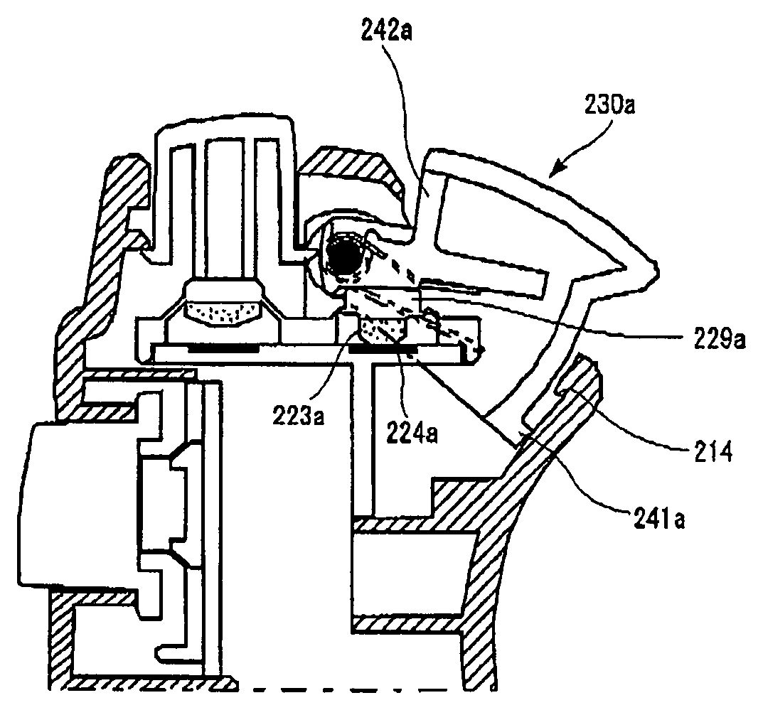
The lower operation button230ahas the projecting part240awhich extends from the surface234a,The projecting part240ais formed to protrude beyond the peripheral area237aof the body part236a. The lower operation button230ais configured as a hollow box, having the following four sides: the surface234awhich serves as a pressing surface; the sidewalls which have the shaft holes in them and extend generally perpendicularly from both sides of the surface234a; and a rear which is formed to make the peripheral area237afrom the lower end of the projecting part240a. A contact piece242ais fixed to inside the lower operation button230a. The contact piece242ais intended to make contact with a contact229aformed on the elastic body222. The contact piece242ais composed of a bearing part which accommodates the rotation shaft232a, and a plate part which extends from the bearing part. The plate part is inserted into guides which are formed on the lower operation button230a. In this state, the rotation shaft232ais inserted through the shaft holes in both sidewalls of the lower operation button230a. The rotation shaft232ais accommodated in the bearing part of the contact piece242a, and the contact piece242ais fixed to the lower operation button230a. Consequently, the contact piece242ais rotated together with the lower operation button230a. It should be appreciated that the contact piece242aand the lower operation button230amay be fixed by other means such as an adhesive, or may be formed integrally. In either case, the contact piece242aand the lower operation button230aare rotated together.
The contact piece242ahas a wall part which extends generally perpendicularly from the plate part. This wall part provides a surface opposite to the rear of the lower operation button230awhen the contact piece242ais fixed to the lower operation button230a. By this configuration, all the externally exposed areas of the lower operation button230aare closed off with surfaces or walls. The contact piece242ahas a flat contact surface, and makes a slidable contact with the flat top of the contact229a. The contact surface is formed on the plate part, between the bearing part and a position at which the wall part is joined on. The contact surface233(seeFIG. 13) of the contact piece242ais made wider than the top of the contact229aso that the top of the contact229acan slide over favorably.
The projecting part240ais formed as an extension of the surface234a. The rear of the projecting part240afacing toward the peripheral area237ais shaped so that the middle finger moved along the case bottom from the peripheral area237ato the projecting part240awill not be hooked by the projecting part240awhich protrudes from the peripheral area237a. That is, the rear of the lower operation button230ais shaped to form an obtuse angle at the border between the peripheral area237aand the projecting part240a, so that the finger can be moved smoothly from the peripheral area237ato the projecting part240a.
The contact229ais urged outwardly from the case, i.e., in the direction away from the resistor224a, by the elastic body228. A conductive member223ahaving elasticity is formed on the underside (inner ceiling surface) of the contact229a. This conductive member223ais opposed to the resistor224awhich is arranged on the internal substrate225. When the lower operation button230ais caused to rotate, the conductive member223acomes into contact with the resistor224a. The conductive member223ahas elasticity and is capable of deformation. The contact area between the conductive member223aand the resistor224avaries with the amount of rotation of the lower operation button230a, and the resistor224aoutputs an analog signal according to the contact area. In this way, the lower operation button230acan thus be operated as an operator capable of making an analog input.
The conductive member223ais shaped like a mound with its top at the center. The conductive member223ais attached to the underside of the contact229aof the elastic body222so that the mound top is opposed to the resistor224a. When the amount of rotation of the lower operation button230aincreases, the conductive member223acan thus be deformed gradually from the top with an increase in the contact area between the conductive member223aand the resistor224a. It should be appreciated that the conductive member223amay be shaped like a bowl with its top at the center. Other shapes having a top at the center, such as a circular cone and a pyramid, may also be used.
The contact piece242amakes contact with the top of the contact229ain a position near the rotation shaft232a. The contact piece242arotates about the rotation shaft232aalong with the lower operation button230a. Thus, the conductive member223awill have to travel by being pressed by a larger distance if the contact piece242amakes contact with the contact229ain a position farther from the rotation shaft232a. This requires that the conductive member223abe made of a highly deformable material since the contact area between the conductive member223aand the resistance224amust change according to the amount of rotation of the lower operation button230a.
When the contact piece242aand the contact229aare put into contact near the rotation shaft232a, on the other hand, it is possible to reduce the maximum amount of pressing of the conductive member223a. This can increase the freedom of selection of the materials suitable for the conductive member223a. It should be appreciated that the contact surface where the contact piece242amakes contact with the contact229ais preferably positioned, for example, closer to the rotation shaft232athan the midpoint between the rotation shaft232aand the peripheral area237a. This can reduce the maximum amount of squeeze of the conductive member223a. Moreover, when the contact229ais positioned to the bottom of the contact piece242a, it is possible to make the elastic body222smaller. This can reduce the amount of material for constituting the elastic body222, and allow efficient use of the space as well.
The lower operation button230ais urged in the direction away from the resistor224aby the elastic body222. A spring member243amay be provided to assist this urging force. The spring member243ais attached to the rotation shaft232awith one end in contact with the contact piece242aand the other end in contact with the internal substrate225, so that an expanding force is produced to urge the contact piece242aoutwardly from the case and the internal substrate225inwardly with regard to the case. The lower operation button230acan thus be urged in a direction away from the internal substrate225. As a result, the lower operation button230acan be suitably maintained in a position projecting from the case when not operated to rotate.
Note that the peripheral area237aof the lower operation button230ahas a projection241aat a position opposite from the projecting part240a, i.e., where to be retracted into the case. A latch part214is formed inside the case, so that the latch part214and the projection241alatch each other to limit the movement of the lower operation button230outwardly from the case.
FIG. 10shows, in cross-sectional view, the state where the lower operation button is pressed in. When the lower operation button230ais operated to rotate, the latch part214and the projection241aare unlatched and the contact229ais pressed in toward the resistor224aas much as the amount of rotation of the contact piece242aat the contact position. Consequently, the conductive member223aand the resistor224acome into contact with each other, and the resistor224aoutputs an analog signal according to the contact area.
FIG. 11shows, in cross-sectional view, the state where the lower operation button is pressed in by the maximum amount of rotation. In this state, the projecting part240ais in contact with the outer periphery of the case, thereby limiting the rotating operation. Here, the contact area between the conductive member223aand the resistor224ais at its maximum, and the resistor224aoutputs the maximum analog signal.
FIG. 12shows the rotating structure of the lower operation button. The lower operation button230ais formed as a box, having the following four sides: the surface234a; the rear which includes the peripheral area237a; and the two sidewalls238which are continuous with the surface234aand the rear. The contact piece242ais attached inside the box of the lower operation button230. The rotation shaft232ais inserted through the shaft holes which are formed in the sidewalls238of the lower operation button230a. The spring member243ais attached to the rotation shaft232a. A single spring member243amay be used as shown in the diagram. Alternatively, two spring members243amay be provided across the bearing part of the contact piece242a.
The rotation shaft232ais pivotally mounted in hole portions of the holder member225a. Each hole portion has a diameter capable of accommodating the rotation shaft232a, and has an opening which is made slightly smaller than the diameter of the rotation shaft232a. The rotation shaft232acan thus be fit into and supported by the holder members225a. By this means, the lower operation button230ais rotatably attached to the internal substrate225. The internal substrate225has a flat part225bfor the elastic body222(not shown) to be placed on. The flat part225bsupports one end of the spring member243a. It should be appreciated that the other end of the spring member243ais supported by the bottom of the contact piece242a. Note that the internal substrate225is common between the lower operation button230aand the upper operation button220a, though not shown in the diagram. The left side of the internal substrate225is thus provided with a structure for attaching the upper operation button220a.
FIG. 13shows the rotating structure of the lower operation button from the bottom. Parallel guides231for attaching and fixing the contact piece242aare formed on both the sidewalls inside the lower operation button230a. Both the sides of the plate part of the contact piece242aare inserted into the parallel guides231. The contact piece242ahas the contact surface233which makes contact with the contact229aof the elastic body222.
The contact surface233is formed flat and at a given angle to the bottom area of the contact piece itself so that the contact229aof the elastic body222is located in a predetermined position with respect to the resistor224abefore being pressed. This predetermined position is determined so as to allow an appropriate amount of play. As a result, a desired analog output can be obtained by a rotating operation on the lower operation button230a.
Up to this point, the present invention has been described in conjunction with the embodiment thereof. This embodiment is given solely by way of illustration. It will be understood by those skilled in the art that various modifications may be made to combinations of the foregoing components and processes, and all such modifications are also intended to fall within the scope of the present invention.
Claims
- An operating device comprising: an operation button supported by a rotation shaft so as to be capable of a rotating operation;a resistor arranged on a substrate;and a conductive member to be pressed against the resistor by the rotating operation on the operation button, the conductive member having elasticity, wherein the resistor outputs an analog signal in accordance with the size of a contact area with the conductive member, the conductive member is shaped like a mound with its top at the center, the conductive member is attached to an elastic body so that the top is opposed to the resistor, the elastic body urging the operation button in a direction away from the resistor, a contact piece for making contact with the elastic body is arranged inside the operation button, and the contact piece makes contact with the elastic body at a position near the rotation shaft.
- The operating device according to claim 1 , wherein a projecting part is formed on a bottom end of the surface of the operation button.
- The operating device according to claim 2 , wherein the operation button is configured as a hollow box, having the following four sides: a surface which is pressed by a user;sidewalls which have shaft holes and extend substantially perpendicularly from both sides of the surface;and a rear which is formed to make a peripheral area from the lower end of the projecting part.
- The operating device according to claim 1 , wherein the contact piece rotates about the rotation shaft along with the operation button.
- The operating device according to claim 4 , wherein a contact surface where the contact piece makes contact with the elastic body is positioned closer to the rotation shaft than the midpoint between the rotation shaft and the peripheral area of the operation button.
- The operating device according to claim 5 , wherein a spring member is attached to the rotation shaft with one end in contact with the contact piece and the other end in contact with the substrate which supports the elastic body, so that the operation button is urged in a direction away from the substrate.
- The operating device according to claim 1 , wherein a spring member which urges the operation button in the direction away from the substrate is attached to the rotation shaft.
- The operating device according to claim 1 , wherein two operation buttons are provided on a case rear at horizontally symmetrical positions in the longitudinal direction of the case rear and positioned so that they are operated with tips of middle fingers of the right hand and the left hand, respectively.
- A game controller implementing an operating device, the operating device comprising: an operation button supported by a rotation ,shaft so as to be capable of a rotating operation;a resistor arranged on a substrate;and a conductive member to be pressed against the resistor by the rotating operation on the operation button, the conductive member having elasticity, wherein the resistor outputs an analog signal in accordance with the size of a contact area with the conductive member, the conductive member is shaped like a mound with its top at the center, the conductive member is attached to an elastic body so that the top is opposed to the resistor, the elastic body urging the operation button in a direction away from the resistor, a contact piece for making contact with the elastic body is arranged inside the operation button, and the contact piece makes contact with the elastic body at a position near the rotation shaft.
- The operating device according to claim 2 , wherein the surface of the operation button is configured to smoothly curve towards the direction of rotation.
- The operating device according to claim 2 , wherein when the operation button is rotated, the projecting part comes into contact with an outer surface of a case to limit the rotating operation.
Disclaimer: Data collected from the USPTO and may be malformed, incomplete, and/or otherwise inaccurate.