U.S. Pat. No. 7,854,500
TAMPER PROOF PRINT CARTRIDGE FOR A VIDEO GAME CONSOLE
AssigneeSilverbrook Research Pty Ltd
Issue DateFebruary 13, 2008
Illustrative Figure
Abstract
This invention relates to a tamper proof print cartridge for a printing device. The cartridge includes a casing defining a media storage portion, an ink storage portion and a media exit. The cartridge also includes a media transport mechanism arranged in said casing and configured to transport a single sheet of media from the media storage portion through the media exit when activated, as well as an ink supply manifold configured to operatively arrange the ink storage portion in fluid communication with the printer.
Description
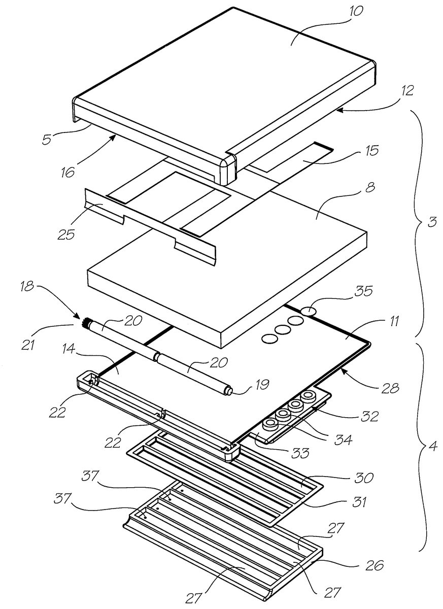
DESCRIPTION OF PREFERRED AND OTHER EMBODIMENTS Referring to the drawings, there is shown a cartridge1for a printing device including a casing shown generally at2. In the illustrated preferred form, the casing is divided into two main portions comprising, a print media supply portion3for housing sheets of paper and the like, and a second storage portion4for housing an ink supply. This cartridge is designed for use with digital printing devices, and is particularly suitable for drop-on-demand ink jet printing devices. The casing2also defines a print media exit opening5that connects with the print media storage portion3and a print media transport mechanism shown generally at7. This transport mechanism is disposed within the print media housing portion3adjacent the print media exit5, such that upon operation it picks up and drives the print media8out through the print media exit opening. Turning first to consider the elements of the print media storage portion of the cartridge, it can be seen to comprise a media top molding10which mates with a corresponding bottom molding11. In this manner the moldings combine to define a generally rectangular print media storage region12in which is housed print media in the form of a stack of paper sheets or cards. The top and bottom moldings10and11are both configured at a front end to define, in combination, the print media exit opening5. In use, the stack of cards8are disposed within the storage region12. These are biased downwardly toward engagement with an upper surface14of the bottom molding11by means of thin metal springs15which bear against an inner lower surface16of the top molding10. The print media transport mechanism of the preferred form illustrated is in the form of a geared pick up roller assembly18. This assembly includes a drive shaft19, pick up rollers20that are rigidly secured to the drive shaft, and an external drive gear21. The transport assembly18is ...
DESCRIPTION OF PREFERRED AND OTHER EMBODIMENTS
Referring to the drawings, there is shown a cartridge1for a printing device including a casing shown generally at2. In the illustrated preferred form, the casing is divided into two main portions comprising, a print media supply portion3for housing sheets of paper and the like, and a second storage portion4for housing an ink supply. This cartridge is designed for use with digital printing devices, and is particularly suitable for drop-on-demand ink jet printing devices.
The casing2also defines a print media exit opening5that connects with the print media storage portion3and a print media transport mechanism shown generally at7. This transport mechanism is disposed within the print media housing portion3adjacent the print media exit5, such that upon operation it picks up and drives the print media8out through the print media exit opening.
Turning first to consider the elements of the print media storage portion of the cartridge, it can be seen to comprise a media top molding10which mates with a corresponding bottom molding11. In this manner the moldings combine to define a generally rectangular print media storage region12in which is housed print media in the form of a stack of paper sheets or cards.
The top and bottom moldings10and11are both configured at a front end to define, in combination, the print media exit opening5. In use, the stack of cards8are disposed within the storage region12. These are biased downwardly toward engagement with an upper surface14of the bottom molding11by means of thin metal springs15which bear against an inner lower surface16of the top molding10.
The print media transport mechanism of the preferred form illustrated is in the form of a geared pick up roller assembly18. This assembly includes a drive shaft19, pick up rollers20that are rigidly secured to the drive shaft, and an external drive gear21.
The transport assembly18is captively retained within the casing portion formed by the top and bottom print media moldings, the drive shaft19being rotatably supported by means of arcuate ribs22formed in a channel23located beneath the exit opening5. The top molding fully encloses the portion of the drive shaft holding the pick up rollers20, but leaves the external drive gear21exposed as shown. In an alternate form, the drive gear may be accessed via an opening in the casing for engagement with a corresponding powered roller on the printer device. A plastic or metal foil25is also provided adjacent the exit opening5. This foil is sized to extend downwardly across the exit such that once the transport mechanism is operated, only a single sheet of paper or card is driven through the exit at any one time.
The ink storage portion4is similarly defined by two separate moldings forming part of the cartridge casing. The primary molding is the ink storage base molding26which is configured to define a plurality of distinct ink chambers27. Ultimately, the chambers are sealed by direct or indirect connection of this base molding26to a cover molding, which in this preferred form is provided by an underside28of the print media storage bottom molding11.
In the preferred form shown, the connection of the two moldings is indirect, as there is provided an intermediate thin walled deformable film30which is preferably initially contoured to nest within the ink chambers27defined in the base molding26. During assembly, the base molding26is sealingly connected with a flange31provided around the periphery of the thin walled deformable film30which in turn is sealingly connected with the underside28of the print media storage bottom molding11.
As can be seen from the drawings, the ink chambers base molding27preferably extends beyond the peripheral edge of the print media storage region above, so as to define an ink supply connection manifold region32. The upper portion of the manifold32is formed as an extension33of the print media storage bottom molding11and includes thereon a plurality of ink connection nozzles34which are closed by means of pierceable ink seals35. In use the ink is stored above the deformable film and is thereby in fluid communication with the ink connection nozzles34. In order to facilitate collapsing of the deformable film30as the ink is withdrawn, air vents37are provided in the ink storage base molding26, preferably at the end remote from the ink nozzles. The various components of the cartridge casing can be assembled by any suitable means including use of adhesives, ultrasonic welding or mechanical fasteners or the like.
A preferred application of the cartridge of the invention as hereinbefore described is for use in a video games console having an integral printer of the kind described in Australian provisional patent application PP7020 and corresponding US application entitled “A video game console with integral printer device” filed concurrently herewith, the contents of which are incorporated herein by reference.
In use, the cartridge of the invention is inserted into an appropriately configured printer device whereby the drive gear21aligns with and engages a corresponding driven gear provided on the printer mechanism. The advantages of this configuration are numerous. Most importantly, the provision of the transportation means within the cartridge, ensures that the paper or other print media is fed out of the cartridge accurately and with minimum initial contamination, as the mechanism and print media are housed within an enclosed unit. In cartridges of the prior art, the cartridge is pressed onto a pick up roller mounted in the printer device, which exposes the paper on the underside. By contrast, the present design allows for greater structural integrity as there is no need to provide an opening that exposes the print media to that same extent. Further, the design provides for a tamper proof unit.
Additional advantages relating to the preferred forms include the provision of seals over the ink outlet nozzles that are pierceable automatically by the printer mechanism upon loading. In this regard, the cartridge is intended only as a single use product. Additionally, the structure of the ink chamber molding whereby the deformable film and base can be molded or joined in a simultaneous operation to form a completely sealed ink chamber, clearly offers manufacturing cost and efficiency advantages.
It will be appreciated by those skilled in the art that whilst the invention has been described with reference to a specific example, the concept can be embodied in many other forms. For example, the print media transport mechanism need not be limited to a pick up roller mechanism, but could include any other suitable mechanisms which can be externally driven from outside the cartridge casing. Similarly, the means of storage of the ink is not limited to the form described and could include the use of other deformable or non-deformable storage means. Accordingly, the preferred embodiment described should be considered in all respects to be illustrative and not restrictive.
Claims
- A tamper proof print cartridge for a printing device, the cartridge comprising: a casing defining a media storage portion, an ink storage portion and a media exit;a media transport mechanism arranged in said casing and configured to transport a single sheet of media from the media storage portion through the media exit when activated;and an ink supply manifold configured to operatively arrange the ink storage portion in fluid communication with the printing device, wherein a foil is located adjacent the media exit, the foil shaped and dimensioned to extend downwardly across the media exit such that once the transport mechanism is operated, only a single sheet of media is driven through the media exit at any one time.
- The print cartridge of claim 1 , wherein the casing includes a top molding which mates with a corresponding bottom molding to define the rectangular print media storage portion in which is housed the print media.
- The print cartridge of claim 2 , wherein the top and bottom moldings are both configured at a front end thereof to define, in combination, the media exit opening, said media being disposed within the storage portion and biased downwardly toward engagement with an upper surface of the bottom molding by means of springs bearing against an inner lower surface of the top molding.
- The print cartridge of claim 1 , wherein the media transport mechanism includes a geared pick up roller assembly having a drive shaft, pick up rollers rigidly secured to the drive shaft, and an external drive gear.
- The print cartridge of claim 4 , wherein the transport mechanism is captively retained within the casing, the drive shaft being rotatably supported by means of arcuate ribs formed in a channel located beneath the media exit, the top molding fully enclosing a portion of the drive shaft holding the pick up rollers, with the external drive gear located outside said casing.
- The print cartridge of claim 1 , wherein the ink storage portion is defined by two separate moldings forming part of the casing defining ink chamber therein, an intermediate thin walled deformable film nesting within said ink chambers, the moldings having air vents to facilitate collapsing of the film when ink is withdrawn therefrom.
Disclaimer: Data collected from the USPTO and may be malformed, incomplete, and/or otherwise inaccurate.