U.S. Pat. No. 7,594,827
SECURE AND/OR LOCKABLE CONNECTING ARRANGEMENT FOR VIDEO GAME SYSTEM
AssigneeNintendo Co., Ltd.
Issue DateOctober 5, 2007
Illustrative Figure
Abstract
Compatible mechanical and/or electrical connections to video game system accessories provide unique shape, design and dimensions that discourage or prevent non-compatible devices from being connected, connector configurations that allow connection only in a proper orientation to ensure electrical compatibility and eliminate the possibility of short-circuits, quick release locking arrangement firmly mechanically holds mating connectors together despite extensive movement of the game player's arms and hands, staged electrical contacting sequence provides proper signal application sequence, and wrist strap to tether handheld remote controller to hand is attached to a locking connector that mates with a connector of the remote controller.
Description
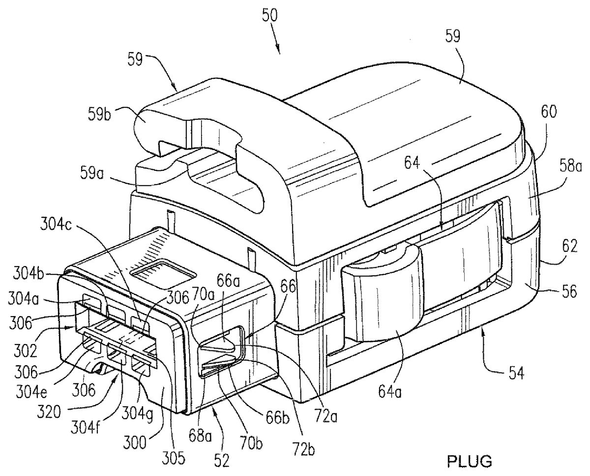
DETAILED DESCRIPTION FIG. 1is a perspective view of an exemplary illustrative non-limiting electrical connector plug50. Electrical connector plug50can be used, for example, to electrically connect a video game accessory including but not limited to a “nunchuk”, “classic controller” or other device to another video game unit such as for example a handheld remote control. These are exemplary illustrative non-limiting examples—connector50can be used to connect any device to any other device. Exemplary illustrative non-limiting electrical connector plug50includes an insertion portion52and a manually grippable portion54. Insertion portion52in one exemplary illustrative non-limiting implementation forms a male portion of a connector that mates with a female connector receptacle or socket100(SeeFIGS. 2Eand following). Grippable portion54is intended to be gripped by human digits (fingers and thumb of the human hand) to allow a user to easily manually, and in a locking manner, insert the connector plug50into and to remove (unlock) the connector plug50from a corresponding mating female connector socket100. In the exemplary illustrative non-limiting implementation shown, grippable portion54includes a generally box-like housing56including grippable side walls58a,58b.Housing56can be of two-piece construction with a top (upper) case portion60joining with a bottom (lower) case portion62. Upper and lower or top and bottom housing case portions60,62can be for example made of molded hard plastic, white “66Nylon” material or any other suitable durable material. The upper and lower housing case portions60,62when coupled together (e.g., using retaining screws, adhesive, or any other convenient fastening system) encapsulate and protect internal portions of the connector assembly to make the connector plug50rugged and allow it to stand up to abuse from children and others. In other exemplary illustrative non-limiting implementations, housing56as shown could be eliminated and some other arrangement used (or omitted as desired) for electrically connecting the connectors of a cable (not shown) to the insertion portion52. In the exemplary illustrative non-limiting implementation, the connector ...
DETAILED DESCRIPTION
FIG. 1is a perspective view of an exemplary illustrative non-limiting electrical connector plug50. Electrical connector plug50can be used, for example, to electrically connect a video game accessory including but not limited to a “nunchuk”, “classic controller” or other device to another video game unit such as for example a handheld remote control. These are exemplary illustrative non-limiting examples—connector50can be used to connect any device to any other device.
Exemplary illustrative non-limiting electrical connector plug50includes an insertion portion52and a manually grippable portion54. Insertion portion52in one exemplary illustrative non-limiting implementation forms a male portion of a connector that mates with a female connector receptacle or socket100(SeeFIGS. 2Eand following). Grippable portion54is intended to be gripped by human digits (fingers and thumb of the human hand) to allow a user to easily manually, and in a locking manner, insert the connector plug50into and to remove (unlock) the connector plug50from a corresponding mating female connector socket100.
In the exemplary illustrative non-limiting implementation shown, grippable portion54includes a generally box-like housing56including grippable side walls58a,58b.Housing56can be of two-piece construction with a top (upper) case portion60joining with a bottom (lower) case portion62. Upper and lower or top and bottom housing case portions60,62can be for example made of molded hard plastic, white “66Nylon” material or any other suitable durable material.
The upper and lower housing case portions60,62when coupled together (e.g., using retaining screws, adhesive, or any other convenient fastening system) encapsulate and protect internal portions of the connector assembly to make the connector plug50rugged and allow it to stand up to abuse from children and others. In other exemplary illustrative non-limiting implementations, housing56as shown could be eliminated and some other arrangement used (or omitted as desired) for electrically connecting the connectors of a cable (not shown) to the insertion portion52.
In the exemplary illustrative non-limiting implementation, the connector plug housing56is of a convenient size for grasping or gripping between a thumb and other digit (e.g., forefinger, middle finger, etc.). SeeFIG. 2Afor example. Dimensions can be for example 17 mm wide by 23.5 mm long by 9.7 mm high in one exemplary illustrative non-limiting implementation. See for exampleFIGS. 3 and 4. Such a size is convenient to be grasped by adults and small children. Other dimensions are possible.
In one exemplary illustrative non-limiting implementation, the male connector plug50has a wrist strap hook59mounted on its housing56. Wrist strap hook59can comprise for example a separate layer of clear strong durable plastic or other similar material providing a ridge59aand a hook structure59b.The purpose of ridge59aand hook structure59bin one exemplary illustrative non-limiting implementation is to retain a nylon or other durable fabric or other wrist strap (e.g., loop) so the device into which the male connector plug50(e.g., a handheld remote controller) can be anchored to the user's hand or wrist.
Since illustrative non-limiting implementations shown herein have a rugged, strong locking mechanism that locks the male connector plug50to a mating female connector socket100(and thus for example to a handheld device which provides the mating female connector socket), it is sufficient in the exemplary illustrative non-limiting implementation to anchor the wrist strap to the connector50which mates with the handheld device (direct connection of the wrist strap to the handheld device itself is thus not necessary in one exemplary illustrative non-limiting implementation). In other implementations, a wrist strap could be anchored directly to the handheld device as opposed to the connector, or it could be omitted. In some exemplary illustrative non-limiting implementations, a sensor of some sort (e.g., optical) is provided to detect whether the wrist strap is being used and in some cases to prevent games or other applications from operating unless the wrist strap is physically in place. The wrist strap could be replaced with a lanyard or any other desired arrangement.
Exemplary Illustrative Non-Limiting Secure Locking Mechanism
An exemplary illustrative non-limiting implementation includes a secure locking mechanism including control arms64, locking nibs or tangs66, and slots or other openings defined within a mating connector in registry with the locking nibs or tangs (seeFIG. 2E). In one exemplary illustrative non-limiting implementation, the thumb for example can be placed into contact with sidewall58aand a finger can be placed into contact with sidewall58b.When the user grasps connector plug50in the way shown inFIG. 2Aand exerts pressure against the sidewalls58a,58b,the user may inwardly depress control arms64a,64b.Arms64a,64bprovide a control feature for the locking mechanism. In more detail, in one exemplary illustrative non-limiting implementation, nibs66are normally biased to project outwardly through openings68. In the exemplary illustrative non-limiting implementation, locking nibs66have ramped, angled or inclined leading edges70and flat (non-angled) following edges72. As shown inFIG. 2C(and see alsoFIG. 8Ainternal view), these retractable nibs66may be integrally formed (e.g., by conventional metal cutting and bending manufacturing processes) on metal members65a,65bthat integrally extend alongside the control arms64a,64b.Two such retractable nibs66are formed on each metal member in the exemplary illustrative non-limiting implementation, although other exemplary embodiments could have one nib, more than two nibs, some locking structure other than a nib, or no locking structure at all.
In the exemplary illustrative non-limiting implementation, control arms64and associated retractable nibs66are mechanically biased (seeFIGS. 1 and 2) such that, at rest, the locking nibs66are fully extended. In the exemplary illustrative non-limiting implementation, nibs66can be forced to retract in two ways: (a) by the user depressing control arms64(for unlocking action), and (b) when the connector plug insertion portion52is inserted into a snugly fitting receptacle (leading up to locking action) which applies retracting pressure directly onto the nibs in a direction that is substantially perpendicular to the direction in which the associated control arm extends. In the exemplary illustrative non-limiting implementation, inserting the connector plug insertion portion52into a female receptacle thus causes a locking action, and user depression of control arms64causes an unlocking action. AsFIG. 8Ashows, the metal members65a,65bare part of a U-shaped structure65that is formed with a stiffening cross base65cthat holds the members65aand65bin an outwardly biased position, but which allows the members (and hence the nibs66) to flex inwardly when pressure is applied to the control arms64a,64b.The metallic structure65can serve double duty as a cable retaining structure.
In more detail, when the user grasps the connector plug housing54between the thumb and a finger and applies pressure to the control arms64and at this stage may or may not cause retractable nibs66to retract (seeFIGS. 2A-2D). The user may insert the plug insertion portion52into a corresponding conformal or other snugly fitting female connector socket100(seeFIGS. 2E-2K) and apply pressure onto the connector to force the connector insertion end further into the female connector socket. A point is reached (seeFIG. 2L) at which the retractable locking nibs66contact the outer edges of the connector socket100and the retractable nib biasing forces offer some resistance to further insertion. If the user continues to increase or otherwise provide applied insertion force, the socket wall will apply a side directed component of that axially directed insertion force to the retractable nibs66to cause the nibs to retract sufficiently to clear the socket opening (seeFIG. 2Mand following). Such retraction of nibs66can occur whether or not the user is applying pressure to the control arms64.
Insertion is smoother and easier if the user is applying pressure to the control arms64, but the force that the insertion wall of the female connector socket applies to the retractable nibs66will cause the nibs to retract irrespective of whether the user is applying force to control arms64. Even though they are partially retracted, the nibs66are outwardly biased in the exemplary illustrative non-limiting implementation such that they remain in close biased contact with the female socket inner wall and exert a frictional force thereon. However, in the exemplary illustrative non-limiting implementation, the contact is between smooth metal surfaces so the frictional insertion force is relatively small, so as not to substantially impede insertion progress. Meanwhile, proper registration between the plug50and the socket is ensured by channel320conformally in registry with an engaging ridge1320disposed on an insertion wall of the female socket.
Thus, in the exemplary illustrative non-limiting implementation shown, retractable nibs66serve to automatically retract as the connector insertion portion52is inserted into a corresponding snugly-fitting female receptacle. If corresponding locking grooves, openings or other structures in registry with locking nibs66are provided, the locking nibs may then automatically protrude into the corresponding structures in registration therewith, such that the trailing edges72abut corresponding edges of grooves, holes or the like and thereby substantially prevent the connector insertion portion52from being removed from a corresponding female receptacle unless either the control arms64are depressed to retract the nibs or a substantial amount of pressure is applied.
FIG. 2D-1shows one such exemplary illustrative non-limiting female connector socket engaging structure including a metal housing201defining a pair of rectangular openings or slots202(only one is shown), each rectangular opening being dimensioned to accept a pair of nibs66, the openings being positioned so that the nibs engage with the opening when male connector plug50is substantially fully inserted into and thus fully mated with female connector socket100.
More specifically, as the user continues to supply insertion force (FIG. 2N,FIG. 2O), the retractable nibs66eventually engage with corresponding slots202defined in the female connector socket wall. In the exemplary illustrative non-limiting implementation, such slots are located and disposed in registry with the nib66positions when the male connector plug50is fully mated with the female connector socket100. Upon such mating connection, the locking nibs66snap outwardly with a positive “click” sound and generate a corresponding tactile snap, thereby letting the user know that the male connector plug50has fully mated with the female connector socket100(FIG. 2P). At this fully mated point, the body of connector50may be in direct contact with an outer surface67defined by a device housing the female socket100. The nib flat engaging surfaces72at this point engage, much as a ratchet engages with a pawl, with edges of the corresponding female socket wall slots202to firmly and strongly lock the connector plug into the mating connector socket100. When locked, the connector plug66can move in and out by a very small distance in the exemplary illustrative non-limiting implementation, but is in fact firmly locked in place so that attempting to pull the connector plug out by force will be unsuccessful unless a very large amount of force is applied.
The locking mechanism (the retractable nib portion of which is shown in more detail in FIG.8A—including the U-shaped structure65) thus provides added degrees of safety and security since the accessory or other device that connector plug50connects to will generally not easily unintentionally separate from the corresponding female connector socket100. This can provide significant benefits for example when a user is holding a video game remote controller with one hand, the remote controller providing a female connector socket100into which a wired connector plug50is inserted. As the user independently swings his or her left and right arms to operate the two different devices, for example, the exemplary illustrative locking mechanism shown including retractable nibs66and corresponding in-registration slots, grooves or other openings or similar structures maintains a firmly-locked electrical and mechanical connection. This prevents electrical connector50from unexpectedly and unintentionally flying out of the corresponding female connector socket100during such arm movements, thereby potentially avoiding injuries, inconvenience, and other potential occurrences caused by unintended disconnection.
In one exemplary illustrative non-limiting implementation, the locking mechanism is designed so it will fail and release the connector plug50from the connector socket100when a very substantial removal force is applied. Such a removal force can for example be somewhat or substantially less than the amount of force required to pull a cable out of the connector plug so that the locking mechanism will forceably release just before the cable strain release fails. Thus, the exemplary illustrative non-limiting locking mechanism is sufficiently stiff so that the connector will not come out accidentally, but is not so stiff that the cord will break first (locking mechanism strength is less than the tensile strength of the cable connected to the male connector50assuming a cable based connection is used).
In normal use, the user can easily withdraw the connector plug50from the connector socket100at any time by applying pressure onto control arms64and thereby cause the control arms to retract inwardly into the connector plug housing. As the user applies force to the control arms64and exceeds the biasing force that maintains the control arms in their outwardly protruding resting positions, the retractable nibs begin to retract into housing54(seeFIG. 2C) and thus disengage from the female connector socket wall slots202or other engaging voids. As the user continues to apply more force, the control arms64continue to travel inwardly into the grippable portion54housing56interior. This causes locking nibs66to further retract into insertion portion52, thereby in one exemplary illustrative non-limiting implementation freeing the connector insertion portion52from a mating receptacle engaging slot or other engaging structure(s). Once the locking nibs66are sufficiently retracted to disengage from corresponding slots, the user can then pull the male connector plug50outwardly away from the female connector socket100to slide out and thereby withdraw the plug from the socket100.
As can be seen inFIG. 2A, the exemplary illustrative non-limiting implementation of male connector plug insertion portion52has one or more longitudinally defined raised portions or ribs69that are intended to maintain frictional contact with the female connector socket inner wall while limiting or reducing the total contact surface area between the withdrawing male connector plug insertion portion52and the female connector socket interior walls. Furthermore, during the operation of withdrawing the connector plug50from the female socket100, the user can continue to maintain strong pressure on the control arms64with the same finger and thumb that is being used to apply withdrawal force in a direction away from the female connector socket100, thereby maintaining the retractable nibs66in substantially or completely retracted positions so the nibs do not substantially add to the amount of force needed to withdraw the connector plug50from the connector socket100. Such a withdrawal operation is therefore simple, does not require much dexterity or applied force, and therefore can be performed even by a small child without difficulty,
In still other exemplary illustrative non-limiting implementations, the retractable nibs66could be formed in other ways and or omitted entirely. Although the exemplary illustrative non-limiting implementation shown includes a locking mechanism including retractable nibs66, other arrangements could be used instead. For example, in some applications, a friction fit alone might be sufficient, or the force of gravity in combination with a friction fit could be used to keep the connector insertion portion52mated with a corresponding female connector receptacle.
Exemplary Male and Female Multilevel Interlocking Configurations
FIG. 6shows a forward-looking plan view looking down onto (and into) the male connector50. One can see the insertion portion52which terminates in a planar surface300composed of plastic or other material. The exemplary illustrative male connector50defines, in this planar surface300, a recess302in which the above-mentioned electrical contact strips are disposed. This recess302is dimensioned to receive a protrusion which is disposed within the female connector (socket). Thus, the male connector50in the exemplary illustration has a portion with a female receptacle for receiving a male protrusion portion of the female socket100. Providing a male plug50with a female socket portion302and providing the female socket100with a male protrusion portion enhances ruggedness, reliability and mechanical strength through the application of multiple interlocking elements that surround one another. In the exemplary illustrative non-limiting implementation, the female socket male protrusion portion is received and surrounded by the male plug recess302, which in turn is surrounded by the larger male projection52that is received within the female socket recess.
The cross-sections of the different interlocking portions can be other than those shown in the Figures discussed above. For example,FIGS. 17a-18pillustrate various connector/plug configurations that include fully or partially compatible mechanical configurations in combination with compatible electrical configurations for the male projection52and female connector socket100, each or any of which may be used to establish the desired electrical connection. However, as mentioned above, entirely different locking mechanisms could be substituted, such locking mechanisms including for example:a lever-operated locking mechanism of the type often seen holding zero insertion force connector pinsa retractable spring or other biased plunger, ball or the likea pure friction fit such as commonly used by USB connectorsa threaded ring or other structure that screws onto a corresponding threaded shaft or other structurethreaded shafts with knurled knobs that mate and interlock with corresponding threaded screw holes, of the type for example used for personal computer parallel and serial cablesside protrusions of the type used commonly for USB male and female connectorsany other suitable locking, retaining or friction fully engaging structural mechanismin suitable applications, a combination of friction and the force of gravity (e.g., docking ports or the like) while connector50is not in physical motion and has a generally downwards orientationany other suitable arrangement (for example, a locking mechanism that engages the slots on the bottom of aFIG. 6Aremote controller rather than engaging the connector itself).other
Exemplary Electrical Connection
Referring again toFIG. 1, the exemplary illustrative non-limiting implementation of male connection plug50includes a keyed or slotted insertion portion52having a substantially planar distal surface300. Substantially planar distal surface300may define a rectangular opening302therein. Rectangular opening302may have channels304a, b, c, e, fandg(sometimes referred to generally as “channels304”) defined therein. A portion305of each channel located at the front of the opening302is closed off with respect to the opening302. Electrical contact strips (e.g., copper or other conductive strips)306may be disposed within the channels304. These copper or other conductive contact strips306are dimensioned and disposed to make good electrical contact with corresponding electrical contacts308of mating female connector socket100. SeeFIG. 12, which shows an exemplary illustrative non-limiting female connector socket100including a metal outer housing402defining an opening404that is dimensioned and shaped to conformaily match and accept, with close frictional engagement, the male connection plug insertion portion52. Thus, for example, the cross-section of the male connection insertion portion52is the “positive” of a shape that is dimensioned to conformally match the shape and size of a “negative” or void defined within the space of opening404defined by the female mating connector socket metal housing402. Of course, metal is just one example, any type of material could be used. Metal may have some advantages in terms of durability, ruggedness, scratch and breakage-resistance and ability to provide RF and noise shielding, but other materials could be used instead or in addition.
Referring again toFIG. 12, a channeled projection406is defined within the space or void404within the female connector socket100. The channeled projection406has channels408a, b, c, d, eandf(sometimes referred to generally as “channels 408”) defined therein, the channels each having a copper or other electrically conductive strip308therein. The female connector channeled projection406is shaped and dimensioned to be inserted within the channeled rectangular opening302within the male connector plug insertion portion distal surface300. When the male plug50mates with the female socket100, the male plug insertion portion52is inserted within the female socket space404as described above, and the female socket channeled projection406is in turn inserted into the male plug rectangular opening302. As the female socket channeled projection406is inserted into the male plug rectangular opening302, the copper or other conductive strips306of the male plug50engage in close electrically conductive sliding contact with corresponding copper or other conductive strips308of the female socket100. Such sliding contact establishes corresponding electrical connections for each of the six pairs of conductors shown. Different numbers of conductors could be used if desired. In some cases, unneeded ones of the conductive strips for particular applications can be omitted or made to be “no connection.” As many connective strips as desired may be provided. In the example shown, a total of six connective strips are provided for six independent electrical connections. In some configurations, not all connections are used (for example, there may be no need in some applications to connect to a “battery” connection). In such cases, the female socket100could be provided with one more (unused) electrical contact than certain configurations of male plug50, whereas other configurations of male plug50could have the same number of electrical contacts as the female socket100, or vice versa. Other applications can of course have other configurations.
FIGS. 6A and 6Bshow details of exemplary illustrative non-limiting copper or other conductive strips308as described above (strips306are similar). See also cross-sectionalFIG. 8. As shown for example inFIG. 6B, each strip308comprises a thin strip of copper or other conductive metal or similar having a bulging portion309formed longitudinally therein. Such bulging or protruding portions can provide good sliding frictional electrical contact while minimizing the amount of force necessary to establish insertion. Furthermore,FIG. 6Bshows that not all of the strips308in the female connector socket100are the same length. In one exemplary illustrative non-limiting implementation, certain of the strips308are shorter than others so that the longer strips make contact with counterpart strips306(which in one exemplary illustrative non-limiting implementation are all the same size) before the shorter ones make contact. For example, in one exemplary illustrative non-limiting implementation, it may be desirable to connect power and ground before making contact between data signal lines. This exemplary illustrated non-limiting connector conductive strip configurations shown provide such staged connections.
FIGS. 7A and 7Bshow electrical wiring diagrams for the paired connection, andFIG. 8shows a cross-section of an exemplary electrical connecting strip structure within male connector50. The electrical connecting strips in the exemplary illustrative non-limiting implementation are made of a highly ductile, relatively stiff conductive material such as copper, aluminum or other metal. As perhaps best seen inFIG. 8, when pressure is applied to the copper strips due to engagement with additional copper strips within the female socket (seeFIG. 6A), the copper strips in the male connector50flex outwardly. Forward ends of the copper strips rest against the closed off portions305of the channels formed on the sidewalk of the opening. An angled portion307projecting inwardly of the male connector copper strips protruding through a slotted opening in the male connector inner contact supporting structure310moves outwardly upon conformal engagement with a corresponding female connector structure. However, the springiness of the copper strips ensures that an inward mechanical bias continues to be applied, resulting in a pressure contact between the male and female connector mating contact strips. Such pressure contact provides effective and reliable highly-conductive electrical conductivity even when the copper strips are worn or oxidized after long use.
One exemplary illustrative non-limiting pin assignment configuration may be as follows for a six-pin male connector:
Pin1: Vcc (3 volts)
Pin2: SCL (serial clock line)
Pin3: “Attach” (connected to Vcc on the male plug50side, sensed on the female socket100side to determine whether a plug is connected or not)
Pin4: V-Batt (can be used for supplying external power through the connectors if desired; this connection is optional in many games)
Pin5: SDA (serial data line)
Pin6: Ground
In one implementation shown inFIG. 6B, Vcc and Ground (1and6) are in an exemplary illustrative non-limiting implementation made longer than the rest of the lines. This means that power and ground will be connected first, before the other signal lines. Furthermore, in the illustrative implementation, ground shield is connected first when the male and female connectors first come into contact (see for exampleFIG. 2I to 2). One exemplary illustrative non-limiting connection sequence is thus:
(1) shielding plates make contact
(2) pins1and6(Vcc and ground) make contact simultaneously
(3) pins2-5(all the rest) make contact.
Other variations are of course possible, e.g., pins2-5make contact first and then power and ground make contact.
Such earlier or staged connection helps to eliminate power surges etc.
FIGS. 3-5show an exemplary illustrative non-limiting cable assembly including a multi-conductor cable with a male connector50at one end and an associated strain reliever1500at an opposite end. The dimensions shown in these drawings (in millimeters) are exemplary (different dimensions could be used if desired).
Keyed Configuration
FIG. 6Bshows that the exemplary illustrative non-limiting implementation of the female connector100channeled projection406is symmetrical such that if taken by itself, it could be turned upside down and still connect equally well with the male connector plug rectangular opening conductors306. However,FIG. 7Areveals that if the exemplary illustrative non-limiting implementation female connector channeled projection406were flipped in its connection orientation, then Vcc and Ground would be reversed, the clock line and the data line would be reversed, and the Attach and V-Batt lines would be reversed. This would not provide a compatible or even working connection in the exemplary illustrative non-limiting implementation. To avoid such inadvertent connection reversals, the outer profile of the male and female connector portions are keyed so they can made in only one orientation. See the longitudinal key slot, trough or channel320in the male connector plug50ofFIG. 2and the corresponding mating and engaging longitudinal plateau450shown in the illustrative exemplary non-limiting female connector socket100shown inFIG. 12. Note also the curved corners in each connector.
While such conformal keying wherein plateau450slides into trough320provides good compatibility, it should be understood that other cross-sectional shapes and profiles could similarly provide partial compatibility and orientation control without being entirely conformal. In particular, although the exemplary illustrative non-limiting implementations shown inFIGS. 1 and 12provide substantially 100% complete conformality between the corresponding mating shapes, less than 100% conformality in shape and/or dimension might be attempted instead to nevertheless providing proper mating orientation, retention, etc.
Different Cross-Sectional Configurations
FIGS. 17A-17Lprovide non-exhaustive examples of female socket insertion cavity cross-sectional shapes that may accept aFIG. 1male connector plug50.FIGS. 18A-18Pprovide non-exhaustive examples of male connector plug cross-sectional shapes that may be accepted by theFIG. 12female connector socket100. There are a very large number of potential variations and possibilities, so the examples shown in these drawings are only representative.
One can assume that an unauthorized or unlicensed hardware manufacturer would try to make his or her connector as different as possible from an authentic connector while still achieving electrical and mechanical compatibility. Elements of electrical and mechanical compatibility include for example proper electrical connection of most of the six electrical connections in the exemplary implementation (at least data and clock line connections would presumably be wanted to provide electrical compatibility, although the pluggable device might be able to provide its own power it would presumably also tie to the common ground connection or to shield but perhaps not to both); and prevention or correction in some way, shape or form from reversed orientation such that those lines are not reversed (although in some circumstances one could envision simply telling the user to try it one way or the other until it works since there are only two possibilities, so long as pin assignment is made carefully to avoid short-circuits).
Elements of mechanical compatibility depend to some extent on the particular application. Rugged, locking, conformal compatibility is probably useful for many applications. However, in applications where not much movement is involved, then perhaps the locking mechanism could be dispensed with or not used, and less conformality might be used. Less conformal might weaken ruggedness, but other precautions (e.g., additional means of attachment or stabilization) might be used to compensate. In some applications such as stationary docking port applications involving very little motion, the aspects of mechanical conformality used for compatibility might be reduced. By setting for these illustrative non-limiting shapes and examples, applicants intend to capture any and all ways to compatibly connect to either theFIG. 1(male) connector or to theFIG. 12(female) connector.
All dimensions herein and in the drawings are in millimeters. Tolerances are plus or minus 0.3 mm.
While the technology herein has been described in connection with exemplary illustrative non-limiting implementations, the invention is not to be limited by the disclosure. For example, other connection means including sleeves, clip down, tie downs, plunger based retaining mechanisms, discrete fingers, capacitive or inductive proximity sensors, optical couplers and other variations could be used instead of what is described above. Although the exemplary illustrative non-limiting implementation connects video game systems, other arrangements are also possible. The invention is intended to be defined by the claims and to cover all corresponding and equivalent arrangements whether or not specifically disclosed herein.
Claims
- A video game accessory connector, comprising: a grasping portion;a male insertion portion that protrudes from the grasping portion, the male insertion portion being insertable into a mating female connector defined within a handheld video game remote control that can sense its own orientation, the male insertion portion comprising: exterior sides and a distal end, a recess that opens onto the distal end being formed in the male insertion portion, recessed channels formed on each of two opposing interior walls of the recess, wherein a portion of each recessed channel located at the opening of the recess is closed off with respect to the recess, and a plurality of electrical contacts that are mounted on the two opposing interior walls of the recess, each electrical contact being mounted in a recessed channel, wherein an intermediate portion of each electrical contact extends outward from the recessed channel and into the recess.
- The connector of claim 1 , further including a channel structure that provides unidirectional interlocking of the male insertion portion with a mating female connector.
- The connector of claim 1 , wherein said electrical contacts in said recess are adapted to make contact in a predetermined time-sequenced order with mating contacts of a mating female connector as said male insertion portion mates with a receiving portion of the mating female connector.
- The connector of claim 3 , wherein ends of the electrical contacts in the recess are located at different depths in the recess such that the electrical contacts will engage mating contacts of a mating female connector in a time-sequenced order as the male insertion portion mates with the mating female connector.
- The connector of claim 3 , wherein ends of the electrical contacts in the recess are all located at substantially the same depth in the recess such that as the male insertion portion is inserted into a receiving portion of a mating female connector that has corresponding electrical contacts located at different depths in the receiving portion, the electrical contacts in the recess of the male insertion portion will mate with the electrical contacts in the mating female connector in a time-sequenced order.
- The connector of claim 1 , further including a wrist strap hook attached to the grasping portion for receiving and securely retaining a wrist strap.
- The connector of claim 1 , wherein said connector further includes a housing that is substantially 17 mm×32 mm and includes an integral cable strain relief.
- The connector of claim 1 , wherein said recess is substantially rectangular in cross-section.
- The connector of claim 1 , wherein said recess is not rectangular in cross-section but is designed and dimensioned to receive and frictionally engage with a protrusion on a mating female connector that is substantially rectangular in cross-section.
- The connector of claim 1 , wherein each of the electrical contacts has a profile that biases the protruding portion outward from the recessed channel and into the recess.
- The connector of claim 10 , wherein the plurality of contacts are oriented such that when the male insertion portion is inserted into a mating female connector, a protrusion in the mating female connector will be received in the recess and the plurality of electrical contacts mounted on the interior walls of the recess will engage corresponding electrical contacts located on opposing exterior sides of the protrusion in the mating female connector.
- The connector of claim 1 , wherein only two electrical contacts are formed on a first interior wall of the recess, and wherein three electrical contacts are formed on a second interior wail of the recess that faces the first interior wall.
- The connector of claim 12 , wherein the two electrical contacts formed on the first interior wall of the recess are located across from electrical contacts located at the ends of the second interior wall of the recess.
- The connector of claim 12 , wherein a concave channel is formed in an exterior wall of the male insertion portion that forms an opposite side of the first interior wall of the recess, the concave channel ensuring unidirectional interlocking of the male insertion portion with a mating female connector.
- The connector of claim 1 , wherein ends of the electrical contacts located adjacent the opening into the recess abut walls of the closed off portions of the recessed channels.
- The connector of claim 1 , wherein the plurality of electrical contacts are shaped such that a distance between two electrical contacts located opposite each other in the recess is smaller at an intermediate depth within the recess than at the opening of the recess.
- The connector of claim 1 , wherein a recess formed in an exterior side of the male insertion portion is designed to receive a protrusion on an interior wall of a mating female connector.
- The connector of claim 1 , further comprising: a nib that is retractably mounted on the male insertion portion;and an actuating element that is mounted on the grasping portion such that a user can depress the actuating element, and wherein the actuating element is coupled to the nib such that when a user depresses the actuating element, the nib is at least partially retracted into the male insertion portion.
- The connector of claim 1 , further comprising: a plurality of nibs that are retractably mounted on the male inspection portion;and at least one actuating element that is mounted on the grasping portion such that a user can depress the at least one actuating element, wherein the at least one actuating clement is coupled to the nibs such that when a user depresses the at least one actuating element, the nibs are at least partially retracted into the male insertion portion.
- The connector of claim 19 , wherein the at least one actuating element comprises plural actuating elements to respectively retract said retractable nibs in response to pressure applied by human digits.
- The connector of claim 20 wherein said nibs are located at remote ends of opposite arms of a single U-shaped structure, and wherein said actuating elements apply said pressure to said arms of the U-shaped structure to thereby cause said nibs to retract.
- The connector of claim 21 , wherein the U-shaped structure comprises a thin, flat strip of metal, and wherein a base of the U-shaped structure comprises a flexible cross-brace connecting said flexible arms.
- The connector of claim 21 , wherein the nibs comprise bent portions of the remote ends of the arms of the U-shaped structure that have been bent 90 degrees with respect to the remaining portions of the ends of the arms.
- The connector of claim 1 , further comprising ribs formed on the exterior sides of the male insertion portion, wherein the ribs ensure that the exterior sides of the male insertion portion make intermittent contact with interior sides of a mating female connector when the male insertion portion is inserted into the mating female connector.
- The connector of claim 1 , wherein the plurality of electrical contacts are movably mounted in the recessed channels, wherein the electrical contacts are biased towards a center of the recess, and wherein ends of the electrical contacts adjacent the opening of the recess abut the closed off portion of the recessed channels to limit how far into the center of the recess the electrical contacts can move.
- The connector of claim 25 , wherein the intermediate portion of each of the electrical contacts comprises a bent portion that extends from one of the recessed channels into the recess.
- A video game accessory connector plug, comprising: an elongated housing having a pair of grippable sides;a male insertion portion having a smaller cross-sectional area than said housing projecting from a forward end of said housing, said male insertion portion having a substantially rectangular cross-sectional shape, with an exterior slot formed in one wall of said male insertion portion, extending along a longitudinal center axis of said housing, and a pair of ribs extending along an exterior surface of an opposite wall of said male insertion portion, said ribs substantially parallel to each other and to said slot;and wherein a planar surface at a distal end of said male insertion portion is formed with a recess;and a plurality of electrical contacts supported in respective channels formed in walls bounding said recess, said electrical contacts arranged in two groups of aligned contacts in facing relationship, on opposite sides of said recess, said contacts including at least a serial data line, a clock line, power and ground.
- The connector of claim 27 , wherein ends of the channels located at the opening into the recess are closed off with respect to the recess.
- The connector of claim 28 , wherein the plurality of electrical contacts are movably mounted in the respective channels, and wherein movement of the electrical contacts from the channels into the recess is limited by engagement of the electrical contacts with the closed off portions of the channels.
- The connector of claim 29 , wherein each of the electrical contacts have a profile which biases an intermediate portion of the contact into the recess.
Disclaimer: Data collected from the USPTO and may be malformed, incomplete, and/or otherwise inaccurate.