U.S. Pat. No. 7,585,225
VIDEO GAME APPARATUS FOR DISPLAYING INFORMATION INDICATING BOUNDARY BETWEEN FIELDS
AssigneeSquare Enix
Issue DateFebruary 21, 2007
U.S. Patent No. 7,585,225: Video game apparatus for displaying information indicating boundary between fields

Summary:
The ‘225 patent describes a system where the environment of the game changes based on the player’s movement during the game. A player, when he looks around him in a game, sees the surrounding environment immediately surrounding his character. The invention calculates the distance between the player and the boundary to determine what display should be shown. Whenever his character reaches the boundary of what the character can see, the invention updates the map and a new section is loaded; this provides a seamless transition from scene to scene without the player having to wait while the new area is loaded.
Abstract:
When movement of a player character is instructed, a position and a direction of the player character after movement thereof are calculated. When the calculated position of the player character after movement thereof is in a moving-to area moved from a current area over a boundary therebetween, map data of a body of the area moved from the current area and map data of a boundary area including a part of the moving-to area are loaded into a RAM from a recording medium, and then the player character is positioned in the moving-to area to be displayed on a display screen. When the player character is positioned in the boundary area near the boundary, a boundary object is displayed at a predetermined position above the boundary in a virtual three-dimensional space.
Illustrative Claim:
1. A game apparatus that executes a game which progresses by moving a player character in a virtual three-dimensional space having a field including a first field and a second field provided therein, the second field communicating with the first field via a predetermined moving path, and displays a screen showing a status of the game on a display device, the game apparatus comprising: a map data fixed storage for storing first map data including graphic data of the entire first field and a partial area of the second field near the moving path, and second map data including graphic data of the entire second field; a movement input for inputting an instruction to move the player character in the virtual three-dimensional space according to a player operation; a mover for moving the player character in the virtual three-dimensional space having the first field and the second field according to the instruction input from the movement input; a high-speed storage, having a faster data reading speed than the map data fixed storage, comprising a character data area for storing character data comprising graphic data of the player character, a map data area for storing map data corresponding to a field that includes a position to which the player character has moved, and a boundary data area for storing boundary data including graphic data of a boundary object indicating a boundary position between the first field and the second field, the boundary object not constituting the field; a map data loader for retrieving the second map data from the map data fixed storage, and for storing the retrieved second map data as a substitute for the first map data having been stored so far when the player character is moved to the second field from the first field; a positional relationship determiner for determining a positional relationship between the boundary position between the first field and the second field and a position of the player character when the player character is positioned in the first field, the positional relationship determiner including a distance determiner for determining a distance between the position of the player character and the boundary position; a boundary object layout device for laying out the boundary object at the boundary position between the first field and the second field when the player character is determined to be positioned in a predetermined range set with the boundary position being a criterion, by the positional relationship determiner; a perspective transformer for performing perspective transformation of a range of the virtual three-dimensional space including the position of the player character, onto a virtual screen from a virtual camera to generate a two-dimensional image to be displayed on the display device based upon the map data stored in the map data area and the character data stored in the character data area, and additionally the boundary data stored in the boundary data area when the boundary object is laid out; and a display controller for displaying the two-dimensional image generated by the perspective transformer on the display device, wherein the boundary object layout device comprises a distance mode changer for changing a display mode of the boundary object laid out at the boundary position in accordance with the distance determined by the distance determiner, and wherein the distance mode changer changes a transparency of the boundary data so that the transparency becomes lower as the distance determined by the distance determiner becomes shorter.
Illustrative Figure
Abstract
When movement of a player character is instructed, a position and a direction of the player character after movement thereof are calculated. When the calculated position of the player character after movement thereof is in a moving-to area moved from a current area over a boundary therebetween, map data of a body of the area moved from the current area and map data of a boundary area including a part of the moving-to area are loaded into a RAM from a recording medium, and then the player character is positioned in the moving-to area to be displayed on a display screen. When the player character is positioned in the boundary area near the boundary, a boundary object is displayed at a predetermined position above the boundary in a virtual three-dimensional space.
Description
DETAILED DESCRIPTION OF THE PREFERRED EMBODIMENT An embodiment of the present invention will be described below with reference to the accompanying drawings. FIG. 1is a block diagram showing the configuration of a video game apparatus which executes a three-dimensional (3D) video game according to the embodiment. As shown inFIG. 1, a video game apparatus1is configured with an apparatus main body101being a main part. The apparatus main body101includes a control unit103, a RAM (Random Access Memory)105, a hard disk drive (HDD)107, a sound processor109, a graphics processor111, a DVD/CD-ROM drive113, a communications interface115, and an interface section117. The sound processor109is connected to a sound output device125(speaker or the like). The graphics processor111is connected to a display device121having a display screen122. A recording medium (DVD-ROM or CD-ROM in this embodiment)131can be mounted into the DVD/CD-ROM drive113. The communications interface115is connected to a network151. The interface section117is connected to an input device (controller)161, and a memory card162. The control unit103includes a CPU (Central Processing Unit) and a ROM (Read Only Memory). The control unit103transfers a program stored in an external storage device (HDD107or recording medium131) to the RAM105and executes the transferred program to control the apparatus main body101. The control unit103has an internal timer. The control unit103has a timer interruption function and an interruption prohibiting function. During interruption prohibition, the control unit103accepts neither a timer interruption nor an input interruption from the input device161. The RAM105is the main storage device of the video game apparatus1and is used as a work area when the control unit103executes a program. The HDD107is a memory area for storing a program and data. The sound processor109interrupts a sound output instruction, when given by the program that is executed by the control unit103, and outputs a sound signal to the sound output device125. The graphics processor111draws an image in ...
DETAILED DESCRIPTION OF THE PREFERRED EMBODIMENT
An embodiment of the present invention will be described below with reference to the accompanying drawings.
FIG. 1is a block diagram showing the configuration of a video game apparatus which executes a three-dimensional (3D) video game according to the embodiment. As shown inFIG. 1, a video game apparatus1is configured with an apparatus main body101being a main part. The apparatus main body101includes a control unit103, a RAM (Random Access Memory)105, a hard disk drive (HDD)107, a sound processor109, a graphics processor111, a DVD/CD-ROM drive113, a communications interface115, and an interface section117.
The sound processor109is connected to a sound output device125(speaker or the like). The graphics processor111is connected to a display device121having a display screen122. A recording medium (DVD-ROM or CD-ROM in this embodiment)131can be mounted into the DVD/CD-ROM drive113. The communications interface115is connected to a network151. The interface section117is connected to an input device (controller)161, and a memory card162.
The control unit103includes a CPU (Central Processing Unit) and a ROM (Read Only Memory). The control unit103transfers a program stored in an external storage device (HDD107or recording medium131) to the RAM105and executes the transferred program to control the apparatus main body101. The control unit103has an internal timer. The control unit103has a timer interruption function and an interruption prohibiting function. During interruption prohibition, the control unit103accepts neither a timer interruption nor an input interruption from the input device161.
The RAM105is the main storage device of the video game apparatus1and is used as a work area when the control unit103executes a program. The HDD107is a memory area for storing a program and data. The sound processor109interrupts a sound output instruction, when given by the program that is executed by the control unit103, and outputs a sound signal to the sound output device125.
The graphics processor111draws an image in a frame memory (frame buffer)112(provided in a RAM included in a chip which constitutes the graphics processor111though the frame memory112is drawn outside the graphics processor111), and outputs a video signal to display the image on the display screen122of the display device121. One frame period of the image included in the video signal output from the graphics processor111is, for example, 1/30 second. The graphics processor111draws one image frame by frame (i.e., every 1/30 second).
The DVD/CD-ROM drive113reads a program and data from the recording medium131. The communications interface115is connected to the network151to communicate with another computer. The input device161has direction keys and a plurality of operation buttons. The direction keys are used to input a direction in which a player character or a cursor displayed on the display screen122is moved. The operation buttons are used to input an instruction to cause the player character to take a predetermined motion. The operation buttons are also used to input a predetermined instruction.
When there is an input from the input device161, the interface section117requests an input interruption to the control unit103and outputs input data to the RAM105. The control unit103interprets the input data output to the RAM105, and performs an arithmetic operation process. During interruption prohibition, the control unit does not accept the input interruption from the interface section117. The interface section117saves data indicating the progress status of the game stored in the RAM105into the memory card162according to an instruction from the control unit103. The interface section117reads data of the interrupted game which is saved in the memory card162, and transfers the data to the RAM105according to an instruction from the control unit103.
A program and data for playing a game on the video game apparatus1are first stored in, for example, the recording medium131. The program and data for playing a game on the video game apparatus1are read from the recording medium131by the DVD/CD-ROM drive113and are loaded into the RAM105at the time the program is executed. The control unit103processes the program and data loaded into the RAM105, sends a draw command to the graphics processor111, and sends a sound output instruction to the sound processor109. Intermediate data while the control unit103is processing the program and data is stored in the RAM105.
Of the RAM105, the HDD107, the recording medium131and the memory card162that constitute a memory hierarchy of the video game apparatus1, the RAM105has the fastest data reading speed, and the HDD107has the next fastest data reading speed. The control unit103reads data necessary for a game in progress from the RAM105with the fastest reading speed, and processes the data. Because the RAM105with the fastest data reading speed has a smaller memory capacity than the HDD107and the recording medium131, only needed data is loaded, part by part, into the RAM105from the recording medium131or so according to the progress of the game as will be described later.
In the video game according to the embodiment, a plurality of areas (three areas A to C in this example) are formed in virtual 3D space as the moving space of a player character. A player progresses the game while moving the player character to the individual areas in order by operating the input device161. A position in the virtual 3D space having a plurality of areas formed therein is uniquely specified by coordinates of a world coordinate system (X, Y, Z), and the specified position naturally specifies in which area the position lies. Graphic data in each area is formed by a plurality of polygons each having a vertex whose coordinates are indicated by coordinates of the world coordinate system (X, Y, Z). A boundary object (to be described later) is likewise formed by a plurality of polygons each having a vertex whose coordinates are indicated by coordinates of the world coordinate system (X, Y, Z).
A player character200is formed by a plurality of polygons each having a vertex whose coordinates are indicated by coordinates of a local coordinate system (x, y, z). The position of the player character200in the virtual 3D space is indicated by coordinates of the world coordinate system (X, Y, Z) of a central point set to approximately the center of the player character200.
The direction of the player character200is expressed by an angle defined by each axis of the local coordinate system with respect to each axis of the world coordinate system. In executing a display process, the coordinates of feature points of the player character200(the vertexes of each polygon) are converted to coordinates of the world coordinate system. The moving direction of the player character200is determined based on the relation between the position of the player character200in the current frame period and the position of the player character200in the previous frame period.
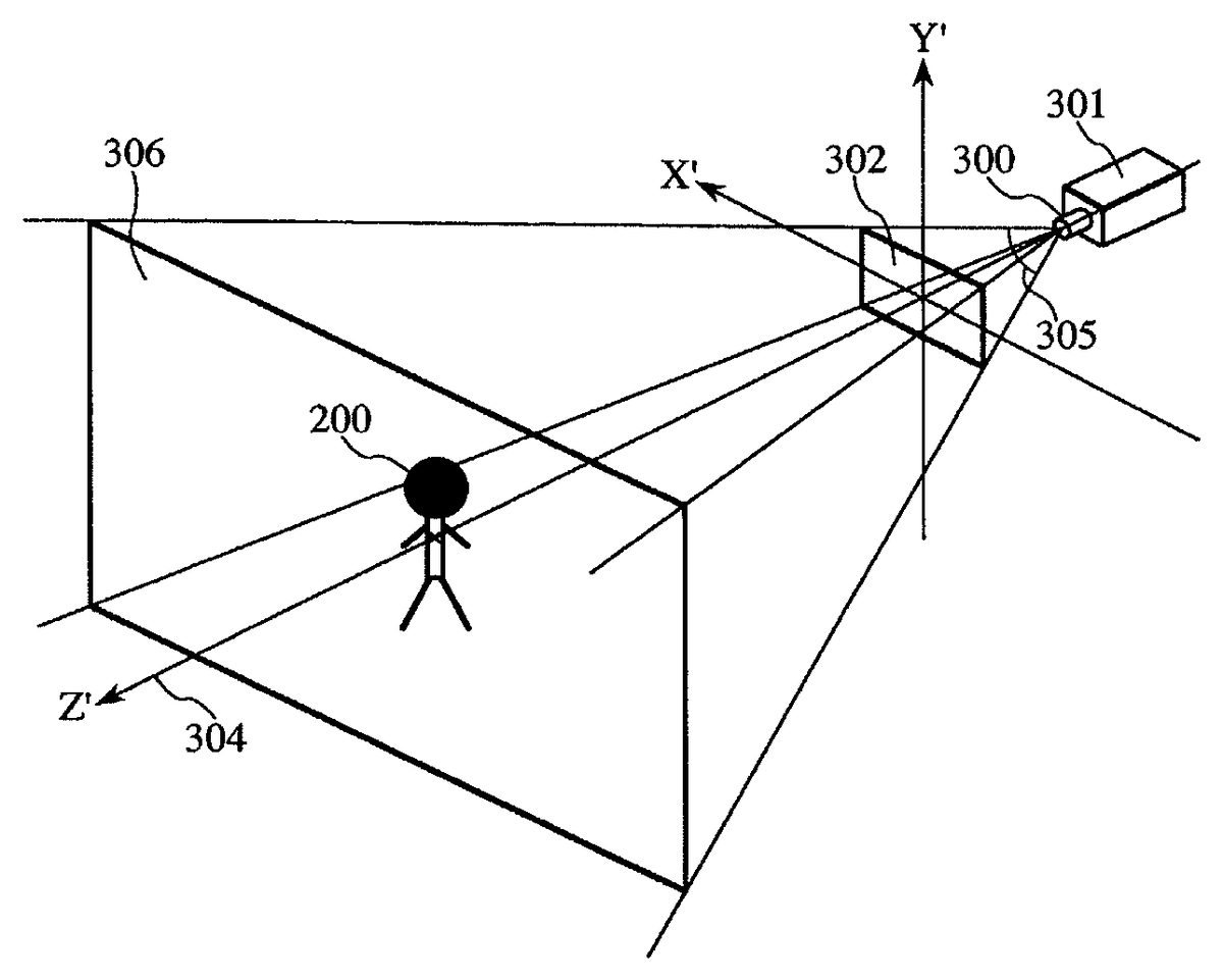
The aspect of the movement of the player character200in each area in the virtual 3D space is shown on the display screen122by perspective transform of the virtual 3D space by a virtual camera, and is identified by the player.FIG. 2is a diagram exemplarily showing the aspect of the perspective transform. A virtual camera301is placed in the virtual 3D space. An image projected onto a virtual screen302by the virtual camera301is an image to be displayed on the display screen122.
The position of the virtual camera301is a view point303, the direction of the virtual camera301is a visual axis304, and an area defined by four lines connecting the view point303to four vertex corners of the virtual screen302is a visual range305. The size of the virtual screen302is fixed. A clip surface306is set at a predetermined distance in the direction of the visual axis304from the view point303. A clipping range (i.e., range where an image is generated in the virtual 3D space by perspective transform) ranges from the virtual screen302to the clip surface306within the range of the visual range305.
The coordinate system that is used to project an image on the virtual screen302is a view coordinate system (X′, Y′, Z′). The direction of the visual axis304is the Z′ axis of the view coordinate. Coordinates of the world coordinate system are converted to coordinates of the view coordinate system based on which a perspective transform process including a process of hidden surface removal to be described next is executed.
In a case where an image projected on the virtual screen302is generated by perspective transform, it is necessary to execute hidden surface removal to remove a surface which is hidden by another object present in front of the object of interest. A Z buffer scheme is used as a method for hidden surface removal in the embodiment. After converting coordinates of the world coordinate system to coordinates of the view coordinate system, the control unit103sends the coordinates of each feature point to the graphics processor111and outputs a draw command. Based on the draw command, the graphics processor111updates the value of a Z buffer so that data (value of Z′) of a point (small point at the Z′ coordinate) in front of each feature point remains, and develops image data for the point into the frame memory112every time update is performed.
Perspective transform is premised on that the position of the view point303of the virtual camera301, the direction of the visual axis304, the size of the visual range305(the distance from the view point303to the virtual screen302), and the distance from the view point303to the clip surface306(hereinafter called “clipping distance”) should be set (the position of the virtual screen302is naturally set when those factors are set). The position of the view point303is kept at a given distance from the player character200, and moves in response to the player character200. The direction of the visual axis304is set in such a way as to be directed toward the central point of the player character200. The size of the visual range305and the clipping distance are basically set to the same size.
FIG. 3is a diagram showing an example of the entire map existing in the virtual 3D space which is used in the 3D video game according to the embodiment. As shown inFIG. 3, three areas (areas A to C) are provided in virtual 3D space400. The player character200can move from a current area on the virtual 3D space400to another area passing through a boundary401(401ab,401bc).
There are a boundary401where a pass condition is set and a boundary401where a pass condition is not set. For the player character200to pass through the boundary401where a pass condition is set, the pass condition should be completed. The boundary401has two states, a passable state and a non-passable state. A boundary401where a pass condition is not set is always in a passable state. A boundary401where a pass condition is set is first in a non-passable state, and can be in a passable state when the pass condition is completed. The boundary401does not indicate the entire range where different areas contact, but indicates that positional range in the range where different areas contact in which the player character200can move through a road or so.
Each area (area A, B, C) connects to another area by one or more boundaries401. The range of the vicinity of the boundary401between adjoining two areas is defined as a boundary area402. The boundary area402includes a partial range of the adjoining two areas in the vicinity of the boundary401therebetween. Each area is composed of an area body (range of each area excluding the boundary area402) and a part of the boundary area402which is included in the area.
Map data of the map shown inFIG. 3is stored in the recording medium131, and is read out into a map data area secured in the RAM105in response to an instruction from the control unit103. A description will now be given of the structure of a map area secured in the RAM105and how to read out map data from the recording medium131into the map data area secured in the RAM105.FIG. 4is a diagram exemplarily showing the relationship between the structure of a memory area of the RAM105and map data500to be stored in the recording medium131.
As shown inFIG. 4, map data500is stored in the recording medium131for each area body and each boundary area402. The map data500of the area body and boundary area402includes a polygon included in the range of each of the area body and boundary area402. The map data500of each boundary area402also includes display data of a boundary set in the boundary area402. Data of polygons constituting a boundary object (to be described later), the display position of boundary forecast information (to be described later), a transparency (initial value) and a display color at the time of displaying the boundary object, etc. are included in the display data of a boundary. The transparency of the boundary object is set in a boundary display decision routine (to be described later) according to the progress of the game.
A plurality of memory areas including a map data area1051and a player character area1052are secured in the RAM105. The map data area1051is secured to store map data500of the area body of an area where the player character200placed, and map data500of the boundary401including a partial range of the area. In an area having a plurality of boundary areas, map data500of the area body of the area and map data500of the plurality of boundary areas402including a partial range of the area are loaded into the map data area1051. As the map data500of the boundary area402is loaded, data of polygons constituting the boundary object or the like is stored in the RAM105.
The player character area1052is secured to store data of polygons constituting the player character200. Data of polygons constituting the player character200is loaded from the recording medium131to be resident in the RAM105. The player character area1052stores data of the position of the player character200in the virtual 3D space400and the direction of the player character200. The direction of the player character200is expressed by an angle defined by each axis of the local coordinate system with respect to each axis of the world coordinate system.
When the game is started (or resumed), a plurality of memory areas including the map data area1051and the player character area1052are secured in the RAM105. The player character200is placed in an initial area. When an interrupted game is resumed, the player character200is placed in an area where the player character200has been present when the game was interrupted. The control unit103loads map data500of the area body of the area where the player character200is to be placed and map data500of the boundary area402including a partial range of the area from the recording medium131to the map data area1051. An image is displayed on the display screen122according to the map data500of the area body and the boundary area402, loaded in the map data area1051.
When the player character200is present in the area A, for example, map data500of the body of the area A and map data500of a boundary area402abare loaded into the map data area1051of the RAM105. Because the boundary area402abincludes a partial range of the area B, the range in the vicinity of a boundary401abbetween the area B and the area A is displayed on the display screen122even when the player character200is present in the area A.
There is a case where boundary forecast information is displayed on the display screen122when the player character200is present in the boundary area402. However, information (lines or so) for discriminating the boundary area402and the area body is not displayed on the display screen122.
When the player character200is present outside the boundary area402of each area, the boundary forecast information is not displayed on the display screen122. When the player character200moves into a predetermined range (e.g., 10) from the boundary401, which range is within the boundary area402of each area, the boundary forecast information is displayed on the display screen122.
Boundary forecast information includes an boundary object and an area name. A plurality of boundary objects are displayed aligned at a predetermined position in the Y direction in parallel to the XZ plane at the coordinate position of the boundary401. Data of each polygon which defines the display position and size of the boundary object is included in the map data500of the boundary area402.
The transparency of the boundary object changes according to the distance from the boundary401. The closer the player character200comes to the boundary401, the more clearly the boundary object is displayed on the display screen122. The boundary object403is displayed in black on the display screen122when the pass condition of the boundary401is not set or is completed, and displayed in red when the pass condition of the boundary401is not completed.
The area name is displayed at a predetermined position above the boundary401. The display position of the area name is normally set in the center of a line (not displayed) above the boundary401. The position of the area name may be shifted as needed. The area name is displayed in front of the image of the virtual 3D space. The area name is simple text information whose font size is registered in a display table601(to be described later).
FIGS. 5A to 5Eshow various tables needed to display boundary forecast information and to move the player character200between areas. The tables inFIGS. 5A to 5Dare stored in a predetermined area secured in the RAM105. More specifically, the tables inFIGS. 5A to 5Dare loaded from the recording medium131into the RAM105when the game is started. A pass flag table inFIG. 5Eis loaded from the recording medium131into the RAM105when the game is started. The pass flag table is saved from the RAM105into the memory card162when the game is interrupted, and is loaded from the memory card162into the RAM105when the game is resumed.
A display table601shown inFIG. 5Ais referred to at the time of displaying boundary forecast information (at the time of executing the boundary display deciding routine to be described later). A distance, a non-transparency coefficient α, and a font size are registered in the display table601in association with one another. A distance X indicates the distance between the boundary401and the player character200(hereinafter called “boundary-player2Q character distance”).
The non-transparency coefficient α is referred to at the time of setting the non-transparency of the boundary object. The maximum value of the non-transparency coefficient is “1” and the minimum value thereof is “0”. The greater the value of the non-transparency coefficient is, the more clearly the boundary object is displayed on the display screen122. When the boundary-player character distance X is greater than 10, the value of the non-transparency coefficient α is “0”. When the boundary-player character distance X lies between 10 and 8, the value of the non-transparency coefficient α increases to “0.15”, “0.30” and “0.80”. When the boundary-player character distance X is equal to or less than 7, the non-transparency coefficient α takes a constant value of “1”.
The font size indicates the size of the font of the area name displayed on the display screen122. When the boundary-player character distance X lies between 10 and 7, the font size increases to “4”, “6”, “8” and “10” as the distance becomes shorter. When the boundary-player character distance X lies between 7 and 0, the font size stays at “10” even if the distance becomes shorter. Although the size of a boundary object in the virtual space does not change, as the player character200moves away from the boundary401to set the view point303farther from the boundary401, the size of the boundary object is displayed smaller on the display screen122.
A moving direction table602shown inFIG. 5Bis referred to at the time of displaying boundary forecast information (at the time of executing the boundary display deciding routine to be described later). The moving direction of the player character200and the non-transparency coefficient β are registered in the moving direction table602in association with each other. In a case where the direction in which the player character200approaches the boundary401is taken as the moving direction, the value of the non-transparency coefficient β becomes “1.0”, whereas in a case where the direction in which the player character200approaches the boundary401is not taken as the moving direction, the value of the non-transparency coefficient β becomes “0.5”.
The non-transparency of a boundary object is decided by multiplying the non-transparency coefficient α decided according to the boundary-player character distance X by the non-transparency coefficient β decided according to the moving direction of the player character200. When the boundary-player character distance X is greater than 10, multiplying 0 as the non-transparency coefficient α by the non-transparency coefficient β sets the value of the non-transparency coefficient to “0”, so that the boundary object403is not displayed on the display screen122. When the boundary-player character distance X lies between 10 and 8, multiplying, as the non-transparency coefficient (*a, the value which becomes greater as the player character200comes closer to the boundary401, makes the value of the non-transparency greater, so that the closer the player character200comes to the boundary401, the more clearly the boundary object is displayed on the display screen122.
In a case where the direction in which the player character200approaches the boundary401is not taken as the moving direction, multiplication of a value smaller than 1 as the non-transparency coefficient β makes the non-transparency smaller, so that the boundary object is displayed on the display screen122unclearly. With the boundary-player character distance X being “8”, for example, When the direction in which the player character200approaches the boundary401is not taken as the moving direction, the non-transparency becomes 0.4, which is obtained by multiplying 0.80 (non-transparency coefficient α) and 0.5 (non-transparency coefficient β).
An area table603shown inFIG. 5Cis referred to when the player character200is to move from the current area to another area (at the time of executing the area moving routine to be described later). Three generally classified pieces of data, an area, a boundary ID and a next area, are registered in the area table603in association with one another.
The area data includes an ID, regional information and a name. The ID is information which uniquely specifies each area. The regional information indicates a region in the virtual 3D space400of each area by the range of coordinates of the world coordinate system. The name is information indicating the name of each area in the game. When the player character200is present in the range of the boundary area402and in a predetermined range (e.g., 10) from the boundary401, the name of a destination area to which the player character200is to move from the current area through the boundary401is displayed on the display screen122.
The data of the boundary ID is information which specifies a boundary where each area contacts another area. Next area data includes an ID, a pass condition and an post-movement initial position. The ID is information indicating a destination area to which the player character200is to move from the current area through the boundary401. The pass condition is a condition which needs to be completed for the player character200to pass through the boundary401. An action the player character200needs to take, an item which the player character200should have, the experience value (or HP) of the player character200needed, etc. may be applied to the pass condition
The experience value is incremented every time the player character200clears an event set in the progress of the game (including a battle with an enemy character), and is stored in a predetermined area secured in the RAM105. Information on an item the player character200currently has is stored in a predetermined area secured in the RAM105. The player character200can obtain an item by picking up the item at a predetermined position in the virtual 3D space400, winning a battle, or buying the item in a shop set in the virtual 3D space400.
For the player character200to move from the area B to the area C passing through a boundary401bc, for example, a pass condition “hold XX” is set. In the boundary401bcwhere the pass condition is set, when a pass flag is set in the pass flag table (to be described later) shown inFIG. 5Ewhen the player character200gets “XX” which is the pass condition. The pass flag for the boundary401where the pass condition is not set has been set since the start of the game.
The post-movement initial position is coordinate information in the virtual 3D space400where the player character200is positioned after moving from one area and the direction of the player character200. In the post-movement initial position is within the boundary area402in an area after movement. The direction of the player character200is such a direction that the back of the player character200faces the boundary401just after moving to a new area.
A boundary table604shown inFIG. 5Dis referred to when the player character200is to move from the current area (at the time of executing the area moving routine to be described later). A boundary ID, position information, and a boundary area ID are registered in the boundary table604in association with one another. The boundary ID is information which uniquely specifies each boundary. The position information indicates the position of the boundary401which is the moving path between areas in the virtual 3D space400by coordinates of the world coordinate system. The boundary area ID is information which uniquely specifies each boundary area402.
A pass flag table605shown inFIG. 5Eis referred to when the player character200is to move from the current area (at the time of executing the area moving routine to be described later). A boundary ID and a pass flag are registered in the pass flag table605in association with each other. The boundary ID is information which uniquely specifies each boundary. The pass flag is information indicating whether or not the pass condition of the boundary401is completed. When the pass flag is set, the player character200can pass through the boundary401and move to a destination area.
Whether or not the boundary401lies in the clipping range of the virtual camera301can be determined by a simple determination. In the simple determination, the Y coordinate of the world coordinate system can be neglected, and the arithmetic operations of the distance and vector are carried out based only on the X coordinate and the Z coordinate. Whether or not the boundary401lies in a range from the virtual screen302to the clip surface306can be determined by determining whether or not the distance from the view point303to each ends of the boundary lies within a predetermined range which is preset according to the distance between the virtual screen302and the clip surface306.
Whether or not the boundary401lies in the range of the visual range305can be determined by determining whether or not the inner product of a vector from the view point303of the virtual camera301toward each end of the boundary401(hereinafter called “boundary-end vector”) and a vector of the visual axis304(hereinafter called “visual-axis vector”) is greater than a threshold preset according to the size of the visual range305. When the inner product of the boundary-end vector and the visual-axis vector is greater than the threshold at either one of both ends of the boundary401, at least a part of the boundary401lies in the range of the visual range305of the virtual camera301.
The following will explain processes which are executed in the video game according to the embodiment. The control unit103and the graphics processor111execute a process of generating an image corresponding to the progress state of the game and displaying the image on the display screen122every frame period. In the following description, what is described as a process of displaying an image on the display screen122is a process of displaying an image which is generated every frame. The descriptions of other processes than those processes unique to the embodiment may be omitted. Information during processing by the control unit103(including information which indicates contents to be displayed) is temporarily stored in the work area of the RAM105.
When the apparatus main body101of the video game apparatus1is powered on, an initial screen for selecting whether to start the video game from the beginning or resume the video game is displayed on the display screen122. Even when a player selects either to start the video game from the beginning or to resume the video game by manipulating the input device161according to the initial screen, the control unit103secures multiple memory areas including the map data area1051and the player character area1052in the RAM105.
When starting the video game from the beginning is selected, initial data is loaded from the recording medium131into the RAM105to start the game process. When resuming the video game is selected, data which was saved at the time of interruption is loaded from the memory card162into the RAM105to start a process in the game. The initial data and the saved data include the map data500and the position and direction of the player character200. The position and direction of the player character200included in the initial data and saved data are loaded into the player character area1052of the RAM105from the recording medium131, and the map data500of the area body about the area where the player character200is located and the map data500of the boundary area402including a partial range of the area are loaded into the player character area1052of the RAM105from the recording medium131according to the position and direction of the player character200.
FIG. 6is a flowchart illustrating a main routine in the video game according to the embodiment. The main routine shown inFIG. 6is executed by a timer interruption which occurs every frame period (every 1/30 second in this example), and is terminated at least within one frame period (within 1/30 second in this example).
In the main routine, the control unit103determines whether or not data which is input from the input device161according to the player's operation of the direction keys, for instructing movement of the player character200is stored in the RAM105(step S101). When data for instructing the movement of the player character200is not stored in the RAM105, the process goes to step S103.
When data for instructing the movement of the player character200is stored in the RAM105, the control unit103acquires the position and direction of the player character200after movement thereof according to the data for instructing the movement of the player character200and the position and direction of the player character200stored in the player character area1052of the RAM105, in the previous frame period (step S102).
When the direction of the data for instructing the movement of the player character200differs from the direction of the body of the player character200in the previous frame period, the control unit103changes the direction of the body of the player character200to match the direction of the data for instructing the movement of the player character200with the direction of the body of the player character200. After the player character200is directed in the direction of the data for instructing the movement of the player character200, the control unit103moves the player character200in the instructed direction. The process goes to step S103.
In step S103, the control unit103determines whether or not the position of the player character200after movement is the position out of the current area. When the player character200is at the position out of the current area, the control unit103determines whether or not the pass flag is set in the pass flag table605for the boundary401through which the player character200will pass (step S104). When the pass flag is not set in the pass flag table605for the boundary401through which the player character200will pass, the player character200cannot go out of the current area, and the routine proceeds directly to step S107.
When the pass flag is set in the pass flag table605for the boundary401through which the player character200will pass, the player character200can go out of the current area. In this case, therefore, the control unit103loads the map data500of a next area into the RAM105from the recording medium131, then executes an area moving routine of placing the player character200to a next area (step S105). The details of the area moving routine will be described later.
When it is determined in the process of step S103that the player character200is at the position where the player character200does not go out of the current area, the control unit103overwrites the position of the player character200, stored in the player character area1052of the RAM105, to the position calculated in the process of step S102(step S106). The routine proceeds to step S107.
In step S107, the control unit103decides the position of the view point303of the virtual camera301according to the position of the player character200. The control unit103decides the direction of the visual axis304so as to be directed toward the central point of the player character200(step S108). The width of the visual range305(the distance from the view point303to the virtual screen302) and the clipping distance (the distance from the view point303to the clip surface306) are kept constant regardless of the position of the view point303or the direction of the visual axis304.
The control unit103determines whether or not the player character200is positioned in the boundary area402(step S109). When the player character200is not positioned in the boundary area402, the process goes directly to step S111. When the player character200is positioned in the boundary area402, on the other hand, the control unit103performs the boundary display deciding routine for displaying boundary forecast information on the display screen122(step S110). The process then goes to step S111.
In step S111, the control unit103performs a display process of perspectively transforming the virtual 3D space including the player character200from the view point303of the virtual camera301, which is decided in the process of step S107, onto the virtual screen302determined by the visual range305, and requesting the graphics processor111to generate a two-dimensional image to be displayed on the display screen122. In making the request, the control unit103supplies the graphics processor111with information which specifies each polygon included in the clipping range, and the transparency, display color, area name and font size which are decided in the boundary display deciding routine inFIG. 8to be described later. When the display process is finished, the control unit103terminates the main routine, and executes the main routine again at the timing of the start of the next frame period.
The graphics processor111which has received the request updates the contents of the Z buffer based on the coordinates of the view coordinate system in such a way that data (value of Z′) at a point on a front screen for each of the points constituting each screen. When the value of the Z buffer is updated, the graphics processor111expand image data for that point in the frame memory112. The graphics processor111also performs processes, such as shading and texture matching, on the image data to be developed. The area name is treated as simple text information and is displayed on the front screen side of the perspectively-transformed image.
The graphics processor111sequentially reads the image data expanded in the frame memory112, adds a sync signal to the image data to generate a video signal, and outputs the video signal to the display device121. The display device121displays an image corresponding to the video signal output from the graphics processor111on the display screen122. As the display screen122is changed over every frame period, the player can view such an image that the player character200moves through the virtual 3D space400and the view point303also moves according to the movement of the player character200.
FIG. 7is a flowchart illustrating the area moving routine in step S105in detail. In the area moving routine, the control unit103prohibits interruption to disable acception of a timer interruption and an input interruption (step S201). The control unit103requests the graphics processor111to display a message “Now loading” on the display screen122indicating that loading map data is in progress (step S202).
The control unit103loads the map data500of the area body for the moving destination area into the map data area1051of the RAM105by referring to the area ID of the moving destination area where the player character200will move through the boundary401, and loads the map data500for all the boundary areas included in the moving destination area by referring to the boundary table604for and all the boundary IDs (step S203). Loading of the map data500takes a considerable time because it needs a process of reading entire map data500corresponding to the area body and the boundary area402from the recording medium131which has a slow data reading speed and writing the read map data500corresponding to the area body and the boundary area402into the RAM105. During loading of the map data500, the display screen122keeps displaying “Now loading”.
The loaded map data500of the boundary area402includes display data of the boundary401. The non-transparency of a boundary object in the display data of the boundary401after loading has the initial value of “0”.
The control unit103places the player character200on the moving destination area at the position and in the direction indicated by the post-movement initial position (step S204). The player character200is displayed on the display screen122with its back facing the boundary401through which the player character200has passed. The control unit103cancels the prohibition of interruption that has been carried out in the process of step S201so as to be able to accept a timer interruption and an input interruption (step S205). Thereafter, the area moving routine is terminated, and the process returns to the flowchart inFIG. 6.
FIG. 8is a flowchart illustrating the boundary display decision routine in step S110in detail. In the boundary display deciding routine, the control unit103specifies a boundary401corresponding to the boundary area402where the player character200is present, and calculates the boundary-player character distance X between the boundary401and the player character200(step S301). The control unit103determines whether or not the calculated boundary-player character distance X lies within the range of 0 to 10 (step S302). When the boundary-player character distance X does not lie within the range of 0 to 10, the boundary display deciding routine is terminated, and the process returns to the flowchart inFIG. 6.
When the boundary-player character distance X lies within the range of 0 to 10, the control unit103determines whether or not the boundary401specified in the process of step S301lies in the clipping range of the virtual camera301by the above-described simple determination (step S303). When the boundary401does not lie in the clipping range, the boundary display deciding routine is terminated, and the process returns to the flowchart inFIG. 6. When the boundary401lies in the clipping range, on the other hand, the control unit103reads the pass condition for the boundary401specified in the process of step S301from the area table603(step S304). The control unit103determines whether or not the pass condition read in the process of step S304is completed (step S305).
When the pass condition is completed, the control unit103sets the display color of the boundary object, corresponding to the boundary401specified in the process of step S301, to black (step S306). The process goes to step S308. When the pass condition is not completed, the control unit103sets the display color of the boundary object, corresponding to the boundary401specified in the process of step S301, to red (step S307). The process goes to step S308.
In step S308, the control unit103multiplies the non-transparency coefficient α determined based on the boundary-player character distance X in the display table601by the non-transparency coefficient β determined based on the progress direction of the player character200in the moving direction table602to decide the non-transparency of the boundary object corresponding to the boundary401specified in the process of step S301.
The control unit103decides the font size of the area name based on the boundary-player character distance X in the display table601(step S309). Thereafter, the boundary display deciding routine is terminated, and the process returns to the flowchart inFIG. 6.
Referring toFIGS. 9A to 9H, details of boundary forecast information to be displayed on the display screen122in the video game will be explained below. The name of an area where the player character200is currently located is displayed at the upper right portion of the display screen122. In any ofFIGS. 9A to 9H, the player character200is present in the boundary area402ab. In any ofFIGS. 9A to 9H, there is the boundary401ab, which is included in the area A or the area B through which the player character200can move from the area A to the area B (or from the area B to the area A). A boundary display line L401indicates a position at a distance of 10 from the boundary401ab. In any ofFIGS. 9A to 9H, the broken line indicating the boundary401aband the broken line indicating the boundary display line L401are not displayed on the display screen122.
InFIG. 9A, the player character200is present in the area A at a position farther than the distance of 10 from the boundary401ab. InFIG. 9A, boundary forecast information is not displayed on the display screen122regardless of whether the player character200is present in the boundary area402abor not. The map data500of the boundary area402abincludes a partial range of the area B in the vicinity of the area A, and the range of the area B included in the clipping range is displayed on the display screen122.
When the player character200is moved to a position within the distance of 10 from the boundary401abin response to the player's instruction from the input device161, what is displayed on the display screen122becomes as shown inFIG. 9B. InFIG. 9B, boundary objects403(403ato403n) are displayed in a line above the boundary401ab, and an area name404is displayed further above the boundary objects403in the center of the boundary. The area name404inFIG. 9Bis “area B” which is the name of the area communicatable via the boundary401ab. The area B is partially displayed on the display screen122. The boundary objects403inFIG. 9Bhave a low non-transparency, and are displayed not clear and small in size. The boundary objects403are displayed in red if the pass condition for the boundary401abis not completed, and in black if the pass condition is completed.
When the player character200is further moved close to the boundary401abin response to the player's instruction from the input device161so that the distance between the player character200and the boundary401abbecomes 7, what is displayed on the display screen122becomes as shown inFIG. 9C. InFIG. 9C, the display size of the area name404becomes larger according to the distance between the player character200and the boundary401ab. Because the non-transparency of the boundary objects403becomes higher, the boundary objects403are displayed more clearly inFIG. 9Cthan inFIG. 9Bif the moving direction of the player character200being the same.
When the player character200is moved closer to the boundary401abin response to the player's instruction from the input device161, what is displayed on the display screen122becomes as shown inFIG. 9D. InFIG. 9D, the area name404is displayed ahead of the player character200. The size of the area name404: is the same as is shown inFIG. 9C.
When the player character200is moved over the boundary401abto enter the area B from the area A in response to the player's instruction from the input device161, what is displayed on the display screen122becomes as shown inFIG. 9E. InFIG. 9E, the map data500of the area body of the area B where the player character200enters after crossing the boundary and the map data500of the boundary areas402ab,402bcincluding a partial range of the area B are loaded into the map data area1051of the RAM105from the recording medium131, and a message “Now loading” indicating that data is being loaded is displayed on the display screen122. When data loading is finished, what is displayed on the display screen122becomes as shown inFIG. 9F.
InFIG. 9F, the player character200is present in the area B. InFIG. 9F, the area name404is displayed as “area A” which is the name of the area communicatable via the boundary401ab. When the player character200is moved over the boundary401abto enter the area A from the area B in response to the player's instruction from the input device161, what is displayed on the display screen122becomes as shown inFIG. 9G. InFIG. 9G, the map data500of the area body of the area A where the player character200enters after crossing the boundary and the map data500of the boundary areas402abincluding a partial range of the area A are loaded into the map data area1051of the RAM105from the recording medium131, and a message “Now loading” is indicating that data is being loaded displayed on the display screen122again. When data loading is finished, what is displayed on the display screen122becomes as shown inFIG. 9H.
According to the video game of the embodiment, as described above, when the player character200is moved to the area B from the area A in response to the player's instruction, the map data500of the area body of the area B, the boundary area402aband the boundary area402bcare loaded and stored into the map data area1051of the RAM105from the recording medium131, in place of the map data500of the area body of the area A and the boundary area402ab. The player needs to wait for the progress of the game while the map data500is being loaded into the RAM105. When the player character200returns to the area A from the area B, the map data500is likewise loaded into the map data area1051or the RAM105, making the period for the player to wait for the progress of the game longer. When the player moves the player character200from the current area A to another area B without knowing the position of the boundary401even if the player character200need not be moved from the current area A to the area B, unnecessary data loading takes place, thus making the player wait for the progress of the game.
However, when the player character200moves to a the distance of 10 or less from the boundary401abof the area A, for example, the boundary objects403are laid out at a predetermined position above the boundary401abin the virtual 3D space and are displayed on the display screen122. In this case, the player can grasp the position of the boundary401abfrom a position distant from the boundary401ab, and will not move the player character200to the area B without noticing the boundary401. This prevents generation of a period where the player needs to wait for the progress of the game for map data500to be wastefully loaded into the RAM105. It is therefore possible to allow the player to quickly and smoothly progress the game.
According to an area where the player character200is positioned, the map data500of the area body of the area and the map data500of the boundary area including a part of the area are loaded to the map data area1051. For example, even when the player character200is positioned in the area A, the area B contiguous to the area A is displayed on the display screen122without breaking at the boundary. Accordingly, the player does not feel awkward at the image of the game displayed on the display screen122.
For example, the player character200at a distance of more than 10 from the boundary401abin the area A will not be moved right away to the area B in response to the player's instruction from the input device161. In a case where the player character200is at a distance of more than 10 from the boundary401ab, therefore, the boundary object403indicating the position of the boundary401abis not necessary for the player in progressing the game. The boundary object403does not exist in a real world. The boundary object403which does not exist in a real world is not displayed on the display screen122, unless otherwise particularly needed in progressing the game, so that the player does not feel awkward as much as possible.
The transparency of the boundary object403is decided by multiplication of the non-transparency coefficient α and the non-transparency coefficient β. The value of the non-transparency coefficient α changes according to the boundary-player character distance X. A change in the transparency of the boundary object403displayed on the display screen122can allow the player to easily determine whether the player character200is approaching the boundary401or not. The value of the non-transparency coefficient α is set so as to become smaller as the boundary-player character distance X becomes shorter. The closer to the boundary401the player character200comes, therefore, the more clearly the boundary object403is displayed on the display screen122. The farther from the boundary401the player character200is positioned, the less necessary the boundary object403becomes in progressing the game. Displaying the boundary object403as a clear image according to the necessity in progressing the game prevents the player from feeling awkward as much as possible.
When the player character200is at a distance of 10 or more from the boundary401, the value of the non-transparency of the boundary object403becomes “0” because the value of the non-transparency coefficient α is “0”, so that the boundary object is not displayed on the display screen122. When the player character200is at a the distance of 10 or less from the boundary401, setting the value of the non-transparency coefficient α greater than “0” allows the boundary object403to be displayed on the display screen122. Because display/non-display of the boundary object403can be executed by controlling the transparency, the processing load can be reduced.
The value of the non-transparency coefficient β changes according to the moving direction of the player character200. When the moving direction of the player character200is not toward the boundary401, the value of the non-transparency coefficient β becomes “0.5”, whereas when the progress direction of the player character200is toward the boundary401, the value of the non-transparency coefficient β becomes “1”. Accordingly, the moving direction of the player character200is not the direction to approach the boundary401, the boundary objects403are unclearly displayed on the display screen122as compared with a case where the moving direction of the player character200is the direction to approach the boundary401.
For example, when the moving direction in which the player character200moves is not toward the boundary401ab, the player character200does not move over the boundary401abto the area B, so that as compared with the case where the moving direction in which the player character200moves is toward the boundary401ab, the necessity of the boundary objects403, in progressing the game is low. By displaying the boundary objects403more clearly as the necessity thereof in progressing the game becomes higher, the player is prevented from feeling awkward as much as possible.
The player character200cannot pass through the boundary401for which the pass condition is not completed. The boundary objects403to be displayed on the display screen122is displayed in red if the pass condition is not completed, and in black if the pass condition is completed. The player can determine according to the color of the boundary objects403displayed on the display screen122whether or not the boundary401is in a passable state where the pass flag is set. This makes it possible to avoid a wasteful input to move the player character200from the current position to an unmovable area, so that the player can progress the game quickly.
The position of the view point303of the virtual camera301is kept at a constant distance from the player character200, and moves according to the movement of the player character200. The farther from the boundary401the player character200is, the farther from the boundary401the virtual camera301becomes. Even if the size of the boundary object403itself does not change, therefore, the size of the boundary object403displayed on the display screen122changes. This makes it possible to naturally change the size of the boundary objects403displayed on the display screen122according to the position of the boundary401by controlling the position of the viewpoint303according to the movement of the player character200.
When the player character200is positioned at a distance of 10 or less from the boundary401, the area name404is displayed above the boundary objects403. The displayed area name404allows the player to easily determine whether or not the player character200has already passed another area which communicates with the current area via the boundary401, making it possible to quickly and smoothly progress the game. The area name404is also information which does not actually exist in a real world, and the higher the necessity of the area name404becomes as the player character200approaches the boundary401, the greater the size of the font displayed on the display screen122becomes. Accordingly, the player does not feel awkward about the display of the area name404as much as possible.
The present invention is not limited to the embodiment, but can be modified and adapted in various other forms. Modifications of the embodiment which can be adapted to the invention will be described below.
In the embodiment, the control unit103loads map data500of the area body of the area where the player character200is positioned and map data500of all the boundary areas402including a partial range of the area from the recording medium131into the map data area1051. The moving-from area from which the player character200moves and the destination area (hereinafter “moving-to area”) to which player character200moves share a boundary area and the map data500of the boundary area has already been loaded into the map data area1051. Therefore, with the map data500of the boundary area common to the moving-from area and the moving-to area left stored in the map data area1051, only the map data500of the area body of the moving-to area and another boundary area including a partial range of the moving-to area may be loaded from the recording medium131into the map data area1051.
In the embodiment, map data500is stored in the recording medium131for each area and body each boundary area402, and map data500of the area body of the area where the player character200exists and the boundary areas402including a partial range of the area is loaded into the map data area1051of the RAM105. However, the form of the map data is not limited to this particular type. Map data including data of a partial range of another adjoining area (range indicated by hatched lines inFIG. 10) may be stored in the recording medium131area by area. In this case, map data500of an area where the player character200exists is to be loaded into the map data area1051of the RAM105from the recording medium131.
FIG. 10is a diagram exemplarily showing the relationship between the structure of the memory area of the RAM105and map data501stored in the recording medium131according to this modification. For example, the map data501of the area A includes the entire area A and a partial range of the area B in contact with the area A (the range which is included in the boundary area402abin the above-described embodiment).
In this modification, when the player character200is in the area A, map data501of the area A including data a part of the adjoining area B is loaded into the map data area1051of the RAM105. With regard to the area B and the area C, map data501corresponding to the area where the player character200is present is loaded into the map data area1051of the RAM105. In this modification, the map data501of each area can include data for displaying a boundary. Because map data501of each area includes data of a part of an adjoining area(s), not only the area where the player character200is present but also the adjoining area are displayed on the display screen122when the player character200is positioned near the boundary401.
In the embodiment, as the transparency changes according to the value of the non-transparency coefficient α that is determined according to the boundary-player character distance X, the display mode of the boundary object403changes. However, the display mode of the boundary object403that is determined according to the boundary-player character distance X may be changed by another method. For example, the brightness or chrominance of the boundary object403may change according to the boundary-player character distance X, thereby changing the display mode.
If the display color of the boundary object403is not changed according to whether the pass condition of the boundary401is completed or not, the color of the boundary object403may be changed according to the boundary-player character distance X. In this case, the boundary object403which becomes visually more discriminatable as the player character200approaches the boundary401can be displayed on the display screen122.
Although the transparency of the boundary object403changes according to the value of the non-transparency coefficient β that is determined according to the moving direction of the player character200in the embodiment, the transparency may be changed by the direction of the player character200itself. This is because the player character200cannot move immediately from the area where the player character200is positioned unless the player character200faces the direction input through the input device161. For example, the transparency of the boundary object403may be calculated by performing multiplication of “1” as the non-transparency coefficient when a line extending in the direction of the player character200intersects the boundary401, but performing multiplication of a value smaller than “1” as the non-transparency coefficient when the line does not intersect the boundary401. The brightness, the chrominance, the display color and the like of the boundary object403may be changed according to the direction of the player character200.
In the embodiment, the boundary object403is displayed regardless of the moving direction of the player character200as long as the boundary-player character distance X is equal to or less than 10. However, “0” may be multiplied as the non-transparency coefficient β of the boundary object403to acquire the non-transparency when the player character200moves away from the boundary401, so that the boundary object403is not displayed on the display screen122. The non-transparency can be set to “0” according to the direction of the player character200itself so as not to display the boundary object403on the display screen122.
When the player character200is moving away from the boundary401, or when the player character200is facing opposite to the boundary401, the player character200does not move over the boundary401to another adjoining area immediately in response to an input from the input device161, and the boundary object403is not needed instantly for the player to progress the game. When the boundary object403is not needed in progressing the game, the boundary object403which does not actually exist in a real world is not displayed on the display screen122, thereby reducing cases where the player feels awkward at the display of the boundary object403.
Although the process of displaying the boundary object403is executed according to whether or not the boundary-player character distance X is equal to or less than 10 in the embodiment, this process is not restrictive. For example, the process of displaying the boundary object403may be executed according to whether or not the boundary401lies in the clipping range of the virtual camera301. In this case, even when the player character200is positioned close to the boundary401, if the boundary is not perspective transformed, the process of displaying the boundary object403is not executed. This simplifies the process and reduces the processing load.
Although whether or not the boundary401lies in the clipping range of the virtual camera301is easily determined by calculating the inner product of the distance and the vector by using only the X coordinates and Z coordinates of the position of the view point303and the positions of both ends of the boundary401in the embodiment, the determination may be made using another method. For example, determination may be made according to a table where the range in which the boundary401is perfective transformed is previously registered.
In the embodiment, the player can recognize whether or not the pass condition of the boundary401is completed by displaying the boundary object403in red. However, the method for notifying whether or not the pass condition is completed is not limited to this. For example, text information indicating that the boundary401is not passable may be displayed on the display screen122. In a case where the player character200has passed the boundary401in the past, such information may also be displayed on the display screen122. The display mode may be determined based not only on the fact of the player character200entering the destination area but also on such a criterion that an event set for the destination area (e.g., a battle with an enemy character) is cleared, or the player character200has acquired all the items placed in the destination area, or the player character200enters a predetermined range set outside the boundary area402of the destination area.
In the embodiment, the area name404and the boundary object403are displayed when the player character200comes within a distance of 10 or more from the boundary401, regardless of whether or not the pass condition of the corresponding boundary401is completed. However, the area name404may be displayed only when the pass condition of the boundary401is completed. In this case, the player can determine that the boundary401is passable if the area name404is displayed, but is not passable if the area name404is not displayed.
The area name404may be displayed when the pass condition of the boundary401is completed, and other information may be displayed when the pass condition of the boundary401is not completed. In this case, the player can determine that the boundary401is passable if the area name404is displayed, but is not passable if information other than the area name404is displayed.
Other information which is displayed when the pass condition of the boundary401is not completed can be information indicating the pass condition itself (e.g., “Experience Value Of YY Needed” or “Item ZZ Needed”), or information suggesting the pass condition (e.g., “Insufficient Experience” or “Some Item Needed”). Other information which is displayed when the pass condition of the boundary401is not completed can be displayed (when the result of decision in step S104is NO). Displaying information indicating the pass condition of the boundary401itself or information suggesting how to complete the pass condition thereof can allow the player to easily recognize what should be done before progressing the game further, thus leading to quicker progress of the game.
The boundary object403may be displayed only when the player character200can pass the boundary401(when the pass condition is completed). If the pass condition of the boundary401is not completed, the player character200does not move to another area and the player will never wait for map data500,501to being loaded in the map data area1051from the recording medium131. The boundary object403which does not actually exist in a real world is not displayed when such does not interfere with the quick progress of the game, thereby reducing cases where the player feels awkward at the display of the boundary object403.
The range of the visual range305(distance from the view point303to the virtual screen302), and the clipping distance (distance from the view point303to the clip surface306) are kept constant regardless of the position of the view point303and the direction of the visual axis304in the embodiment, but are not restrictive. The range of the visual range305may be changed, for example, according to the positions of members of a group to which the player character200belongs, the size of an enemy character to battle against, the position of the player character200, the position of the boundary401or the like. The range of the visual range305may be kept constant normally, but may be changed when an exceptional event occurs. When the range of the visual range305or the clipping distance changes, the value of the threshold for determining whether the boundary401is in the clipping range or not also changes according to the range of the visual range305or the clipping distance.
In the embodiment, when the boundary-player character distance X becomes 10 or less, a value greater than “0” is used as the value of the non-transparency coefficient α for calculating the non-transparency of the boundary object403to display the boundary object403on the display screen122in a transparent or semitransparent manner. Instead, a flag which is set for each boundary401depending on whether or not the boundary-player character distance X is 10 or less may be stored in the RAM105. When the flag is set, the boundary object403is displayed on the display screen122.
In the embodiment, the apparatus main body101which is an exclusive apparatus is used as the platform to execute a video game. However, any apparatus, such as a general-purpose personal computer, which has components similar to those of the apparatus main body101and has a function of writing an image may be used as well. The invention may be adapted to a portable game apparatus having the display device121and the sound output device125accommodated in the same casing. The invention can be adapted to not only a game which is played by a stand-alone type video game apparatus or the like but also a network game which is played by multiple players using multiple video game apparatuses or the like connected to the network151.
A semiconductor memory card can be used as the recording medium131instead of a DVD-ROM or CD-ROM. In this case, a card slot for loading the memory card can be provided in place of the DVD/CD-ROM drive113. In case of a general-purpose personal computer, the program and data according to the invention may be stored beforehand in the HDD107to be distributed to users instead of being stored in the recording medium131for distribution. According to the physical form and the distribution form of hardware, any type of recording medium can be used to store the program and data according to the invention and distributed to users.
In the embodiment, the program and data of the video game apparatus1are stored in the recording medium131to be distributed to users. Alternatively, the program and data of the video game apparatus1may be stored in a fixed disk drive provided in a server apparatus located on the network151, and may be distributed to the apparatus main body101over the network151. In the video game apparatus1, the program and data which have been received from the server apparatus by the communications interface115can be stored in the HDD107and loaded into the RAM105at the time the program is executed.
Claims
- A game apparatus that executes a game which progresses by moving a player character in a virtual three-dimensional space having a field including a first field and a second field provided therein, the second field communicating with the first field via a predetermined moving path, and displays a screen showing a status of the game on a display device, the game apparatus comprising: a map data fixed storage for storing first map data including graphic data of the entire first field and a partial area of the second field near the moving path, and second map data including graphic data of the entire second field;a movement input for inputting an instruction to move the player character in the virtual three-dimensional space according to a player operation;a mover for moving the player character in the virtual three-dimensional space having the first field and the second field according to the instruction input from the movement input;a high-speed storage, having a faster data reading speed than the map data fixed storage, comprising a character data area for storing character data comprising graphic data of the player character, a map data area for storing map data corresponding to a field that includes a position to which the player character has moved, and a boundary data area for storing boundary data including graphic data of a boundary object indicating a boundary position between the first field and the second field, the boundary object not constituting the field;a map data loader for retrieving the second map data from the map data fixed storage, and for storing the retrieved second map data as a substitute for the first map data having been stored so far when the player character is moved to the second field from the first field;a positional relationship determiner for determining a positional relationship between the boundary position between the first field and the second field and a position of the player character when the player character is positioned in the first field, the positional relationship determiner including a distance determiner for determining a distance between the position of the player character and the boundary position;a boundary object layout device for laying out the boundary object at the boundary position between the first field and the second field when the player character is determined to be positioned in a predetermined range set with the boundary position being a criterion, by the positional relationship determiner;a perspective transformer for performing perspective transformation of a range of the virtual three-dimensional space including the position of the player character, onto a virtual screen from a virtual camera to generate a two-dimensional image to be displayed on the display device based upon the map data stored in the map data area and the character data stored in the character data area, and additionally the boundary data stored in the boundary data area when the boundary object is laid out;and a display controller for displaying the two-dimensional image generated by the perspective transformer on the display device, wherein the boundary object layout device comprises a distance mode changer for changing a display mode of the boundary object laid out at the boundary position in accordance with the distance determined by the distance determiner, and wherein the distance mode changer changes a transparency of the boundary data so that the transparency becomes lower as the distance determined by the distance determiner becomes shorter.
- A game apparatus that executes a game which progresses by moving a player character in a virtual three-dimensional space having a field including a first field and a second field provided therein, the second field communicating with the first field via a predetermined moving path, and displays a screen showing a status of the game on a display device, the game apparatus comprising: a map data fixed storage for storing first map data including graphic data of the entire first field and a partial area of the second field near the moving path, and second map data including graphic data of the entire second field;a movement input for inputting an instruction to move the player character in the virtual three-dimensional space according to a player operation;a mover for moving the player character in the virtual three-dimensional space having the first field and the second field according to the instruction input from the movement input;a high-speed storage, having a faster data reading speed than the map data fixed storage, comprising a character data area for storing character data comprising graphic data of the player character, a map data area for storing map data corresponding to a field that includes a position to which the player character has moved, and a boundary data area for storing boundary data including graphic data of a boundary object indicating a boundary position between the first field and the second field, the boundary object not constituting the field;a map data loader for retrieving the second map data from the map data fixed storage, and for storing the retrieved second map data as a substitute for the first map data having been stored so far when the player character is moved to the second field from the first field;a positional relationship determiner for determining a positional relationship between the boundary position between the first field and the second field and a position of the player character when the player character is positioned in the first field;a direction determiner for determining a direction in which the player character moves by the mover;a boundary object layout device for laying out the boundary object at the boundary position between the first field and the second field on a condition that the direction determined by the direction determiner is facing a predetermined direction with respect to the boundary position when the player character is determined to be positioned in a predetermined range set with the boundary position being a criterion by the positional relationship determiner;a perspective transformer for performing perspective transformation of a range of the virtual three-dimensional space including the position of the player character, onto a virtual screen from a virtual camera to generate a two-dimensional image to be displayed on the display device based upon the map data stored in the map data area and the character data stored in the character data area, and additionally the boundary data stored in the boundary data area when the boundary object is laid out;and a display controller for displaying the two-dimensional image generated by the perspective transformer on the display device, wherein the boundary object layout device includes direction mode changer for changing a display mode of the boundary object laid out at the boundary position according to the direction determined by the direction determiner.
- A game apparatus that executes a game which progresses by moving the player character in a virtual three-dimensional space having a field including a first field and a second field provided therein, the second field communicating with the first field via a predetermined moving path, and displays a screen showing a status of the game on a display device, the game apparatus comprising: a map data fixed storage for storing first map data including graphic data having the entire first field and a partial area of the second field near the moving path, and second map data including graphic data having the entire second field;a movement input for inputting an instruction to move the player character in the virtual three-dimensional space according to a player operation;a mover for moving the player character in the virtual three-dimensional space having the first field and the second field according to the instruction input from the movement input, and including direction changeover unit for changing a direction in which the player character faces according to the instruction input from the movement input;a high-speed storage, having a faster data reading speed than the map data fixed storage, comprising a character data area for storing character data comprising graphic data of the player character, a map data area for storing map data corresponding to a field that includes a position to which the player character has moved, and a boundary data area for storing boundary data including graphic data of a boundary object indicating a boundary position between the first field and the second field, the boundary object not constituting the field;a map data loader for retrieving the second map data from the map data fixed storage, and for storing the retrieved second map data as a substitute for the first map data having been stored so far when the player character is moved to the second field from the first field;a positional relationship determiner for determining a positional relationship between the boundary position between the first field and the second field and a position of the player character when the player character is positioned in the first field;a direction determiner for determining a facing direction of the player character when the player character is moved within a predetermined range by the mover;a boundary object layout device for laying out the boundary object at the boundary position between the first field and the second field on a condition that the direction determined by the direction determiner is facing a predetermined direction with respect to the boundary position when the player character is determined to be positioned in a predetermined range set with the boundary position being a criterion, by the positional relationship determiner;a perspective transformer for performing perspective transformation of a range of the virtual three-dimensional space including the position of the player character, onto a virtual screen from a virtual camera to generate a two-dimensional image to be displayed on the display device based upon the map data stored in the map data area and the character data stored in the character data area, and additionally the boundary data stored in the boundary data area when the boundary object is laid out;and a display controller for displaying the two-dimensional image generated by the perspective transformer on the display device, wherein the boundary object layout device includes direction mode changer for changing a display mode of the boundary object laid out at the boundary position according to the direction determined by the direction determiner.
- The game apparatus according to claim 1 , wherein the positional relationship determiner includes the distance determiner for determining the distance between the position of the player character and the boundary position, and the boundary object layout device for laying out the boundary object at the boundary position when the distance between the position of the player character and the boundary position is determined to be within a predetermined distance.
- The game apparatus according to claim 1 , wherein the boundary object layout device lays out the boundary object at the boundary position by changing the transparency of the boundary data stored in the boundary data area to be non-transparent or semitransparent when the player character is determined to be positioned in the predetermined range set with the boundary position being a criterion, by the positional relationship determiner.
- The game apparatus according to claim 1 , further comprising: a movement restriction switcher for switching the state of the game between a cross-field movement disabled state, where the player character cannot move to the second field from the first field, and a cross-field movement enabled state, where the player character can move to the second field from the first field, according to a condition fulfilled in a progress of the game;and a cross-field movement enable determiner for determining whether the state of the game is switched to the cross-field movement enabled state by the movement restriction switcher, when the player character is moved within the predetermined range by the mover, and wherein the boundary object layout device lays out a boundary object whose display mode differs from that of a boundary object which is laid out when the state of the game is determined to be switched to the cross-field movement disabled state, when the state of the game is determined to be switched to the cross-field movement enabled state by the cross-field movement enable determiner.
- The game apparatus according to claim 6 , further comprising cross-field movement enablement display for displaying, on the display device, information indicating a condition to be fulfilled to switch from the cross-field movement disabled state to the cross-field movement enabled state by the movement restriction switcher when it is determined by the cross-field movement enable determiner that the state of the game is switched to the cross-field movement enabled state.
- The game apparatus according to claim 7 , wherein the cross-field movement enablement display displays, on the display device, information indicating the condition to be fulfilled to switch from the cross-field movement disabled state to the cross-field movement enabled state by the movement restriction switcher on a condition that an instruction to move the player character over a boundary to the second field from the first field is input from the movement input when it is determined by the cross-field movement enable determiner that the state of the game is switched to the cross-field movement enabled state.
- The game apparatus according to claim 1 , further comprising a perspective transform range determiner for determining whether the boundary position between the first field and the second field is included in the range to be perspectively transformed by the perspective transformer, and wherein the boundary object layout device lays out the boundary object at the boundary position on a condition that it is determined that the boundary position is included in the range to be perspectively transformed by the perspective transform range determiner.
- The game apparatus according to claim 1 , wherein the boundary object has a predetermined fixed size, and the perspective transformer includes a virtual camera mover for moving a position of the virtual camera in response to movement of the player character, when the player character is moved by the mover.
- The game apparatus according to claim 1 , further comprising: a second field determiner for determining whether the second field is included in the range to be perspectively transformed by the perspective transformer when the player character is positioned in the first field;and a second field information adding unit for placing information indicating the second field over a position corresponding to the second field of the two-dimensional image to be generated by the perspective transformer when it is determined that the second field is included in the range by the second field determiner.
- A method for displaying a field boundary to execute a game in a computer apparatus wherein the game progresses by moving a player character in a virtual three-dimensional space having a field including a first field and a second field provided therein, the second field communicating with the first field via a predetermined moving path, the computer apparatus comprising: an external storage device for storing map data including graphic data of the entire first field and a partial area of the second field near the moving path, and second map data including graphic data of the entire second field;a main storage device, having a faster data reading speed than the external storage device, comprising a character position area for storing a position of the player character, a character data area for storing character data comprising graphic data of the player character, a map data area for storing map data corresponding to a field that includes a position to which the player character has moved, and a boundary data area for storing boundary data including graphic data of a boundary object laid out at a boundary position between the first field and the second field, the boundary object not constituting the field;a movement input device for inputting an instruction to move the player character in the virtual three-dimensional space according to a player operation;a display device for displaying an image indicating a state of the game;and a frame memory for drawing the image to be displayed on the display device, the method for displaying the field boundary comprising: moving the player character in the virtual three-dimensional space having the first field and the second field according to the instruction input from the movement input device and storing the position to which the player character moved in the character position area;retrieving the second map data from the external storage device, loading and storing the retrieved second map data in the map data area as a substitute for the first map data having been stored so far when the player character is moved to the second field from the first field;determining a distance between the position of the player character and a boundary position as a positional relationship between the boundary position between the first field and the second field and the position of the player character when the position of the player character stored in the character position area is in the first field;laying out the boundary data in the boundary data area, storing information indicating a position of the boundary data in a predetermined area of a main storage device and changing a transparency of the boundary data so that the transparency becomes lower as a distance between the player character and the boundary position becomes shorter when the player character is determined to be positioned in a predetermined range set with the boundary position being a criterion;performing perspective transformation of a range of the virtual three-dimensional space including the position of the player character, onto a virtual screen from a virtual camera to draw the generated two-dimensional image in the frame memory based upon the map data stored in the map data area and the character data stored in the character data area, and additionally the boundary data stored in the boundary data area when the information indicating the position of the boundary data is stored;and displaying the two-dimensional image drawn in the frame memory on the display device.
- A method for displaying a field boundary to execute a game in a computer apparatus where in the game progresses by moving a player character in a virtual three-dimensional space having a field including a first field and a second field provided therein, the second field communicating with the first field via a predetermined moving path, the computer apparatus comprising: an external storage device for storing first map data including graphic data of the entire first field and a partial area of the second field near the moving path, and second map data including graphic data of the entire second field;a main storage device, having a faster data reading speed than the external storage device, comprising a character position area for storing a position of the player character, a character data area for storing character data comprising graphic data of the player character, a map data area for storing map data corresponding to a field that includes a position to which the player character has moved, and a boundary data area for storing boundary data including graphic data of a boundary object laid out at a boundary position between the first field and the second field, the boundary object not constituting the field;a movement input device for inputting an instruction to move the player character in the virtual three-dimensional space according to a player operation;a display device for displaying an image indicating a state of the game;and a frame memory for drawing the image to be displayed on the display device, the method for displaying the field boundary comprising: moving the player character in the virtual three-dimensional space having the first field and the second field according to the instruction input from the movement input device and storing the position to which the player character moved in the character position area;retrieving the second map data from the external storage device, loading and storing the retrieved second map data in the map data area as a substitute for the first map data having been stored so far when the player character is moved to the second field from the first field;determining a positional relationship between the boundary position between the first field and the second field and the position of the player character when the position of the player character stored in the character position area is in the first field;determining a direction in which the player character moves;laying out the boundary data in the boundary data area, storing information indicating a position of the boundary data in a predetermined area of a main storage device and changing a display mode of the boundary object according to the determined direction to which the player character moves on a condition that the direction in which the player character moves is facing a predetermined direction with respect to the boundary position when the player character is determined to be positioned in a predetermined range set with the boundary position being a criterion;performing perspective transformation of a range of the virtual three-dimensional space including the position of the player character, onto a virtual screen from a virtual camera to draw the generated two-dimensional image in the frame memory based upon the map data stored in the map data area and the character data stored in the character data area, and additionally the boundary data stored in the boundary data area when the information indicating the position of the boundary data is stored;and displaying the two-dimensional image drawn in the frame memory on the display device.
- A method for displaying a field boundary to execute a game in a computer apparatus wherein the game progresses by moving a player character in a virtual three-dimensional space having a field including a first field and a second field provided therein, the second field communicating with the first field via a predetermined moving path, the computer apparatus comprising: an external storage device for storing first map data including graphic data of the entire first field and a partial area of the second field near the moving path, and second map data including graphic data of the entire second field;a main storage device, having a faster data reading speed than the external storage device, comprising a character position area for storing a position of the player character, a character data area for storing character data comprising graphic data of the player character, a map area for storing map data corresponding to a field that includes a position to which the player character has moved, and a boundary data area for storing boundary data including graphic data of a boundary object laid out at a boundary position between the first field and the second field, the boundary object not constituting the field;a movement input for inputting an instruction to move the player character in the virtual three-dimensional space according to a player operation;a display device for displaying an image indicating a state of the game;and a frame memory for drawing the image to be displayed on the display device, the method for displaying the field boundary comprising: moving the player character in the virtual three-dimensional space having the first field and the second field, changing a direction in which the player character faces according to the instruction input from the movement input device and storing the position to which the player character has moved and the changed direction in the character position area;retrieving the second map data from the external storage device, loading and storing the retrieved second map data in the map data area as a substitute for the first map data having been stored so far when the player character is moved to the second field from the first field;determining a positional relationship between the boundary position, between the first field and the second field, and the position of the player character when the position of the player character stored in the character position area is in the first field;determining the direction in which the player character faces when the position of the player character stored in the character position area is in the first field;laying out the boundary data in the boundary data area, storing information indicating a position of the boundary data in a predetermined area of the main storage device and changing a display mode of the boundary object according to the predetermined direction in which the player character faces on a condition that the direction in which the player character faces is facing a predetermined direction with respect to the boundary position when the player character is determined to be positioned in a predetermined range set with the boundary position being a criterion;performing perspective transformation of a range of the virtual three-dimensional space including the position of the player character, onto a virtual screen from a virtual camera to draw the generated two-dimensional image in the frame memory based upon the map data stored in the map data area and the character data stored in the character data area, and additionally the boundary data stored in the boundary data area when the information indicating the position of the boundary data is stored;and displaying the two-dimensional image drawn in the frame memory on the display device.
- A computer readable medium that stores a program to be executed by a computer apparatus connected to a display device which displays a screen showing a status of a game which progresses by moving a player character in a virtual three-dimensional space having a field including a first field and a second field provided therein, the second field communicating with the first field via a predetermined moving path, the computer apparatus including: an external storage device for storing first map data including graphic data of the entire first field and a partial area of the second field near the moving path, and second map data including graphic data of the entire second field;a main storage device, having a faster data reading speed than the external storage device, comprising a character position area for storing a position of the player character, a map data area for storing map data corresponding to a field that includes a position to which the player character has moved, and a boundary data area for storing boundary data including graphic data of a boundary object laid out at a boundary position between the first field and the second field, the boundary object not constituting the field;and a movement input device for inputting an instruction to move the player character in the virtual three-dimensional space according to a player operation, the program on the computer readable medium causing the computer apparatus to execute: moving the player character in the virtual three-dimensional space having the first field and the second field according to the instruction input from the movement input device;retrieving the second map data from the external storage device, and storing the retrieved second map data as a substitute for the first map data having been stored so far when the player character is moved to the second field from the first field;determining a positional relationship between the boundary position between the first field and the second field and the position of the player character when the player character is positioned in the first field, the determining including determining a distance between the position of the player character and the boundary position;laying out the boundary object at the boundary position between the first field and the second field when the player character is determined to be positioned in a predetermined range set with the boundary position being a criterion, by the positional relationship determination;performing a perspective transformation of a range of the virtual three-dimensional space including the position of the player character, onto a virtual screen from a virtual camera to generate a two-dimensional image to be displayed on the display device based upon map data stored in the map data area and character data stored in the character data area, and additionally the boundary data stored in the boundary data area when the boundary object is laid out;and displaying the two-dimensional image generated by the perspective transformation on the display device, wherein laying out the boundary object includes changing a display mode of the boundary object laid out at the boundary position in accordance with the distance determined by the distance determining, and the display mode changing changes a transparency of the boundary data so that the transparency becomes lower as the distance determined by the distance determining becomes shorter.
- A computer reachable medium that stores a program to be executed by a computer apparatus connected to a display device which displays a screen showing a status of a game which progresses by moving a player character in a virtual three-dimensional space having a field including a first field and a second field provided therein, the second field communicating with the first field via a predetermined moving path, the computer apparatus including: an external storage device for storing first map data including graphic data of the entire first field and a partial area of the second field near the moving path, and second map data including graphic data of the entire second field;a main storage device, having a faster data reading speed than the external storage device, comprising a character position area for storing a position of the player character, a map data area for storing map data corresponding to a field that includes a position to which the player character has moved, and a boundary data area for storing boundary data including graphic data of a boundary object laid out at a boundary position between the first field and the second field, the boundary object not constituting the field;and a movement input device for inputting an instruction to move the player character in the virtual three-dimensional space according to a player operation, the program on the computer readable medium causing the computer apparatus to execute: moving the player character in the virtual three-dimensional space having the first field and the second field according to the instruction input from the movement input device;retrieving the second map data from the external storage device, and storing the retrieved second map data as a substitute for the first map data having been stored so far when the player character is moved to the second field from the first field;determining a positional relationship between the boundary position between the first field and the second field and the position of the player character when the player character is positioned in the first field;determining a direction in which the player character moves by the moving;laying out the boundary object at the boundary position on a condition that the direction determined by the direction determining is facing a predetermined direction with respect to the boundary position when the player character is determined to be positioned in a predetermined range set with the boundary position being a criterion, by the positional relationship determining;performing perspective transformation of a range of the virtual three-dimensional space including the position of the player character, onto a virtual screen from a virtual camera to generate a two-dimensional image to be displayed on the display device based upon the map data stored in the map data area and character data stored in the character data area, and additionally the boundary data stored in the boundary data area when the boundary object is laid out;and displaying the two-dimensional image generated by the perspective transformation on the display device, and wherein the laying out includes changing a display mode of the boundary object laid out at the boundary position in accordance with the direction determined by the direction determining.
- A computer readable medium that stores a program to be executed by a computer apparatus connected to a display device which displays a screen showing a status of a game which progresses by moving a player character in a virtual three-dimensional space having a field including a first field and a second field provided therein, the second field communicating with the first field via a predetermined moving path, the computer apparatus including: an external storage device for storing first map data including graphic data of the entire first field and a partial area of the second field near the moving path, and second map data including graphic data of the entire second field;a main storage device, having a faster data reading speed than the external storage device, comprising a character position area for storing a position of the player character, a map data area for storing map data corresponding to a field that includes a position to which the player character has moved, and a boundary data area for storing boundary data including graphic data of a boundary object laid out at a boundary position between the first field and the second field, the boundary object not constituting the field;and a movement input device for inputting an instruction to move the player character in the virtual three-dimensional space according to a player operation, the program on the computer readable medium causing the computer apparatus to execute: moving the player character in the virtual three-dimensional space having the first field and the second field according to the instruction input from the movement input device, and including changing a direction in which the player character faces according to the instruction input from the movement input device;retrieving the second map data from the external storage device, and storing the retrieved second map data as a substitute for the first map data having been stored so far when the player character is moved to the second field from the first field;determining a positional relationship between the boundary position, between the first field and the second field, and the position of the player character when the player character is positioned in the first field;determining a facing direction of the player character when the player character is moved within a predetermined range by the moving;laying out the boundary object at the boundary position between the first field and the second field on a condition that the direction determined by the facing direction determining is facing a predetermined direction with respect to the boundary position when the player character is determined to be positioned in a predetermined range set with the boundary position being a criterion, by the positional relationship determining;performing perspective transformation of a range of the virtual three-dimensional space including the position of the player character, onto a virtual screen from a virtual camera to generate a two-dimensional image to be displayed on the display device based upon map data stored in the map data area and character data stored in the character data area, and additionally the boundary data stored in the boundary data area when the boundary object is laid out;and displaying the two-dimensional image generated by the perspective transformation on the display device, wherein the boundary object laying out includes changing a display mode of the boundary object laid out at the boundary position in accordance with the direction determined by the direction determining.
- The game apparatus according to claims 2 , wherein the positional relationship determiner includes the distance determiner for determining the distance between the position of the player character and the boundary position, and the boundary object layout device for laying out the boundary object at the boundary position when the distance between the position of the player character and the boundary position is determined to be within a predetermined distance.
- The game apparatus according to claim 2 , wherein the boundary object layout device lays out the boundary object at the boundary position by changing the transparency of the boundary data stored in the boundary data area to be non-transparent or semitransparent when the player character is determined to be positioned in the predetermined range set with the boundary position being a criterion, by the positional relationship determiner.
- The game apparatus according to claim 2 , further comprising: a movement restriction switcher for switching the state of the game between a cross-field movement disabled state, where the player character cannot move to the second field from the first field, and a cross-field movement enabled state, where the player character can move to the second field from the first field, according to a condition fulfilled in a progress of the game;and a cross-field movement enable determiner for determining whether the state of the game is switched to the cross-field movement enabled state by the movement restriction switcher, when the player character is moved within the predetermined range by the mover, and wherein the boundary object layout device lays out a boundary object whose display mode differs from that of a boundary object which is laid out when the state of the game is determined to be switched to the cross-field movement disabled state, when the state of the game is determined to be switched to the cross-field movement enabled state by the cross-field movement enable determiner.
Disclaimer: Data collected from the USPTO and may be malformed, incomplete, and/or otherwise inaccurate.