U.S. Pat. No. 7,500,916
GAME STRATEGY ANALYSIS TOOL GENERATING A TWO DIMENSIONAL IMAGE OVERLAID WITH TELEMETRY DATA
AssigneeMicrosoft Corporation
Issue DateNovember 7, 2005
U.S. Patent No. 7,500,916: Game strategy analysis tool generating a two dimensional image overlaid with telemetry data

Summary:
The ‘916 patent describes a computing network where, while one or more players play online, computer-readable media storage units collect telemetry data while the game is being played. The units then analyze this data and view location information of players throughout the game. Once the game is complete, all of the different player’s data is combined into one file to reduce redundancy. One reason behind this telemetry data collection is so that less skilled players can be matched up with more advanced players and thus will be afforded the opportunity to research the more experienced tactics. The telemetry data also collects stats throughout the game. For example, in Halo 2, the killer and the victim are recorded throughout the game and a running total of both a team score and an individual’s kill count are kept. Finally, the telemetry data is collected in order to identify and punish cheaters. Whenever a person is deemed a cheater they are effectively barred from logging back into the game.
Abstract:
Methods and systems for recording and analyzing game session telemetry data are disclosed. A game console records telemetry data during a game session of a video game. The telemetry data may include location and time information for a player character performing various events in the video game. The telemetry data is sent to a title server corresponding to the video game, and the title server analyzes the data and stores the data in a database. A user, via a web site, can subsequently query the telemetry data stored in the database for user-specified criteria. A two-dimensional image of a view of the simulated environment within the video game is generated, overlaid with the location and time-based telemetry data, and is sent to the user for review and analysis.
Illustrative Claim:
1. In a computing network which includes one or more game consoles connectable to a secure private network on which players of an online video game can log on for purposes of playing the online video game and competing with one another, one or more computer-readable media storing computer-executable instructions for performing a method for collecting player telemetry data while the game is played and for analyzing the telemetry data recorded during a game session so that less skilled players have an opportunity to research tactics of more advanced players, wherein said video game comprises a simulated environment in which the game is played, and said telemetry data comprises location information corresponding to one or more events occurring within the simulated environment, and wherein said method is comprised of steps for: at one or more of the player consoles, recording game session telemetry data by either recording at least timestamp and location data for one or more predefined events which occur while the video game is being played, or recording player inputs and periodically recording
Illustrative Figure
Abstract
Methods and systems for recording and analyzing game session telemetry data are disclosed. A game console records telemetry data during a game session of a video game. The telemetry data may include location and time information for a player character performing various events in the video game. The telemetry data is sent to a title server corresponding to the video game, and the title server analyzes the data and stores the data in a database. A user, via a web site, can subsequently query the telemetry data stored in the database for user-specified criteria. A two-dimensional image of a view of the simulated environment within the video game is generated, overlaid with the location and time-based telemetry data, and is sent to the user for review and analysis.
Description
DETAILED DESCRIPTION In the following description of the various aspects, reference is made to the accompanying drawings, which form a part hereof, and in which is shown by way of illustration various features described herein may be practiced. It is to be understood that other embodiments may be used and structural and functional modifications may be made. FIG. 1illustrates an example of a suitable gaming system environment100on which computer games, video games, and or other electronic games (collectively referred to herein as computer or video games) may be played. The gaming system environment100is only one example of a suitable computing environment and is not intended to suggest any limitation as to the scope of use or functionality of the features described herein. Neither should the gaming system environment100be interpreted as having any dependency or requirement relating to any one or combination of components illustrated in the illustrative operating gaming system environment100. Aspects described herein are operational with numerous other general purpose or special purpose computing system environments or configurations. Examples of well known computing systems, environments, and/or configurations that may be suitable for use include, but are not limited to, personal computers; server computers; portable and hand-held devices such as personal digital assistants (PDAs), tablet PCs or laptop PCs; multiprocessor systems; microprocessor-based systems; set top boxes; programmable consumer electronics; network PCs; minicomputers; mainframe computers; electronic game consoles, distributed computing environments that include any of the above systems or devices; and the like. Aspects herein may be described in the general context of computer-executable instructions, such as program modules, being executed by a computer. Generally, program modules include routines, programs, objects, components, data structures, etc. that perform particular tasks or implement particular abstract data types. The features described herein may also be practiced in distributed computing environments where tasks are performed ...
DETAILED DESCRIPTION
In the following description of the various aspects, reference is made to the accompanying drawings, which form a part hereof, and in which is shown by way of illustration various features described herein may be practiced. It is to be understood that other embodiments may be used and structural and functional modifications may be made.
FIG. 1illustrates an example of a suitable gaming system environment100on which computer games, video games, and or other electronic games (collectively referred to herein as computer or video games) may be played. The gaming system environment100is only one example of a suitable computing environment and is not intended to suggest any limitation as to the scope of use or functionality of the features described herein. Neither should the gaming system environment100be interpreted as having any dependency or requirement relating to any one or combination of components illustrated in the illustrative operating gaming system environment100.
Aspects described herein are operational with numerous other general purpose or special purpose computing system environments or configurations. Examples of well known computing systems, environments, and/or configurations that may be suitable for use include, but are not limited to, personal computers; server computers; portable and hand-held devices such as personal digital assistants (PDAs), tablet PCs or laptop PCs; multiprocessor systems; microprocessor-based systems; set top boxes; programmable consumer electronics; network PCs; minicomputers; mainframe computers; electronic game consoles, distributed computing environments that include any of the above systems or devices; and the like.
Aspects herein may be described in the general context of computer-executable instructions, such as program modules, being executed by a computer. Generally, program modules include routines, programs, objects, components, data structures, etc. that perform particular tasks or implement particular abstract data types. The features described herein may also be practiced in distributed computing environments where tasks are performed by remote processing devices that are linked through a communications network. In a distributed computing environment, program modules may be located in both local and remote computer storage media including memory storage devices.
FIG. 1shows an exemplary gaming system100. Gaming system100may include a game console102and one or more handheld controllers, as represented by controllers104(1) and104(2). The game console102may be equipped with an internal or external hard disk drive and a portable media drive106that supports various forms of portable storage media as represented by optical storage disc108. Examples of suitable portable storage media include DVD, CD-ROM, game discs, and so forth.
Game console102may have a number of slots110on its front face to support up to four controllers, although the number and arrangement of slots may be modified. A power button112and an eject button114are also positioned on the front face of the game console102. The power button112switches power to the game console and the eject button114alternately opens and closes a tray of the portable media drive106to allow insertion and extraction of the storage disc108.
Game console102may connect to a television or other display (not shown) via A/V interfacing cables120. A power cable122provides power to the game console. Game console102may further be configured with broadband network capabilities, as represented by the cable or modem connector124to facilitate access to a network, such as the Internet. Connector124may also be fitted with a wireless adapter to connect to one or more wireless networks.
Each controller104may be coupled to the game console102via a wire or wireless interface. In the illustrated implementation, the controllers are USB (Universal Serial Bus) compatible and are connected to the console102via USB cables130. Controller102may be equipped with any of a wide variety of user interaction mechanisms. As illustrated inFIG. 1, each controller104may be equipped with two thumbsticks132(1) and132(2), a D-pad134, buttons136(e.g., ‘A’, ‘B’, ‘X’, ‘Y’), and two triggers138. The thumbsticks132may be analog directional control units, and may include analog potentiometers to detect a degree of position in the X- and Y- coordinates. D-pad134may be a directional pad, with inputs for entering directional commands such as up, down, left and right, or combinations of these directions (e.g., upper-left). D-pad134may also be analog, and may provide input as to a degree of pressure used to press in a particular direction. These mechanisms are merely representative, and other known gaming mechanisms may be substituted for or added to those shown inFIG. 1.
A memory unit (MU)140may be inserted into the controller104to provide additional and portable storage. Portable memory units enable users to store game parameters and user accounts, and port them for play on other consoles. In the described implementation, each controller is configured to accommodate two memory units140, although more or less than two units may be employed in other implementations. A headset142may be connected to the controller104or game console102to provide audio communication capabilities. Headset142may include a microphone for audio input and one or more speakers for audio output.
Gaming system100is capable of playing, for example, games, music, and videos. With the different storage offerings, titles can be played from the hard disk drive or the portable medium108in drive106, from an online source, or from a memory unit140. For security, in some embodiments executable code can only be run from the portable medium108. A sample of what gaming system100is capable of playing include game titles played from CD and DVD discs, from the hard disk drive, or from an online source; digital music played from a CD in the portable media drive106, from a file on the hard disk drive (e.g., “WINDOWS™” Media Audio (WMA) format), or from online streaming sources; and digital audio/video played from a DVD disc in the portable media drive106, from a file on the hard disk drive (e.g., Active Streaming Format), or from online streaming sources.
FIG. 2shows functional components of the gaming system100in more detail. The game console102has a central processing unit (CPU)200and a memory controller202that facilitates processor access to various types of memory, including a flash ROM (Read Only Memory)204, a RAM (Random Access Memory)206, a hard disk drive208, and the portable media drive106. The CPU200is equipped with a level 1 cache210and a level 2 cache212to temporarily store data and hence reduce the number of memory access cycles, thereby improving processing speed and throughput.
The CPU200, memory controller202, and various memory devices are interconnected via one or more buses, including serial and parallel buses, a memory bus, a peripheral bus, and a processor or local bus using any of a variety of bus architectures. By way of example, such architectures can include an Industry Standard Architecture (ISA) bus, a Micro Channel Architecture (MCA) bus, an Enhanced ISA (EISA) bus, a Video Electronics Standards Association (VESA) local bus, and a Peripheral Component Interconnects (PCI) bus also known as a Mezzanine bus.
As one suitable implementation, the CPU200, memory controller202, ROM204, and RAM206are integrated onto a common module214. In this implementation, ROM204is configured as a flash ROM that is connected to the memory controller202and a ROM bus (not shown). RAM206is configured as multiple DDR SDRAM (Double Data Rate Synchronous Dynamic RAM) that are independently controlled by the memory controller202via separate buses (not shown). The hard disk drive208and portable media drive106are connected to the memory controller via the PCI bus and an ATA (AT Attachment) bus216.
A 3D graphics processing unit220and a video encoder222form a video processing pipeline for high speed and high resolution graphics processing. Data is carried from the graphics processing unit220to the video encoder222via a digital video bus (not shown). An audio processing unit224and an audio codec (coder/decoder)226form a corresponding audio processing pipeline with high fidelity and stereo processing. Audio data is carried between the audio processing unit224and the audio codec226via a communication link (not shown). The video and audio processing pipelines output data to an A/V (audio/video) port228for transmission to the television or other display. In the illustrated implementation, the video and audio processing components220-228are mounted on the module214.
Also implemented on the module214are a USB host controller230and a network interface232. The USB host controller230is coupled to the CPU200and the memory controller202via a bus (e.g., PCI bus) and serves as host for the peripheral controllers104(1)-104(4). The network interface232provides access to a network (e.g., Internet, home network, etc.) and may be any of a wide variety of various wire or wireless interface components including an Ethernet card, a modem, a Bluetooth module, a cable modem, and the like.
The game console102has two dual controller support subassemblies240(1) and240(2), with each subassembly supporting two game controllers104(1)-104(4). A front panel I/O subassembly242supports the functionality of the power button112and the eject button114, as well as any LEDs (light emitting diodes) or other indicators exposed on the outer surface of the game console. The subassemblies240(1),240(2), and242are coupled to the module214via one or more cable assemblies244.
Eight memory units140(1)-140(8) are illustrated as being connectable to the four controllers104(1)-104(4), i.e., two memory units for each controller. Each memory unit140offers additional storage on which games, game parameters, and other data may be stored. When inserted into a controller, the memory unit140can be accessed by the memory controller202.
A system power supply module250provides power to the components of the gaming system100. A fan252cools the circuitry within the game console102.
The game console102implements a uniform media portal model that provides a consistent user interface and navigation hierarchy to move users through various entertainment areas. The portal model offers a convenient way to access content from multiple different media types—game data, audio data, and video data—regardless of the media type inserted into the portable media drive106.
To implement the uniform media portal model, a console user interface (UI) application260is stored on the hard disk drive208. When the game console is powered on, various portions of the console application260are loaded into RAM206and/or caches210,212and executed on the CPU200. The console application260presents a graphical user interface that provides a consistent user experience when navigating to different media types available on the game console.
The gaming system100may be operated as a standalone system by simply connecting the system to a television or other display. In this standalone mode, the gaming system100allows one or more players to play games, watch movies, or listen to music. However, with the integration of broadband connectivity made available through the network interface232, the gaming system100may further be operated as a participant in a larger network gaming community. This network gaming environment is described next.
FIG. 3shows an exemplary network gaming environment300that interconnects multiple gaming systems100(1), . . . ,100(g) via a network302. The network302represents any of a wide variety of data communications networks. It may include public portions (e.g., the Internet) as well as private portions (e.g., a residential Local Area Network (LAN)), as well as combinations of public and private portions. Network302may be implemented using any one or more of a wide variety of conventional communications media including both wired and wireless media. Any of a wide variety of communications protocols can be used to communicate data via network302, including both public and proprietary protocols. Examples of such protocols include TCP/IP, IPX/SPX, NetBEUI, etc.
In addition to gaming systems100, one or more online services304(1), . . . ,304(s) may be accessible via the network302to provide various services for the participants, such as hosting online games, serving downloadable music or video files, hosting gaming competitions, serving streaming audio/video files, and the like. The network gaming environment300may further involve a key distribution center306that plays a role in authenticating individual players and/or gaming systems100to one another as well as online services304. The distribution center306distributes keys and service tickets to valid participants that may then be used to form games amongst multiple players or to purchase services from the online services304.
The network gaming environment300introduces another memory source available to individual gaming systems100—online storage. In addition to the portable storage medium108, the hard disk drive208, and the memory unit(s)140, the gaming system100(1) can also access data files available at remote storage locations via the network302, as exemplified by remote storage308at online service304(s).
FIG. 4is a block diagram of another illustrative online gaming environment400, e.g. “XBOX™ LIVE™” by Microsoft Corporation of Redmond, Wash. Multiple game consoles402(1),402(2), . . . ,402(n) are coupled to a security gateway404via a network406. Each game console402can be, for example, a game console102ofFIG. 1orFIG. 2. Network406represents any one or more of a variety of conventional data communications networks. Network406will typically include packet switched networks, but may also include circuit switched networks. Network406can include wire and/or wireless portions. In one exemplary implementation, network406includes the Internet and may optionally include one or more local area networks (LANs) and/or wide area networks (WANs). At least a part of network406is a public network, which refers to a network that is publicly-accessible. Virtually anyone can access the public network.
In some situations, network406includes a LAN (e.g., a home network), with a routing device situated between game console402and security gateway404. This routing device may perform network address translation (NAT), allowing the multiple devices on the LAN to share the same IP address on the Internet, and also operating as a firewall to protect the device(s) on the LAN from access by malicious or mischievous users via the Internet.
Security gateway404operates as a gateway between public network406and a private network408. Private network408can be any of a wide variety of conventional networks, such as a local area network. Private network408, as well as other devices discussed in more detail below, is within a data center410that operates as a secure zone. Data center410is made up of trusted devices communicating via trusted communications. Thus, encryption and authentication within secure zone410is not necessary. The private nature of network408refers to the restricted accessibility of network408—access to network408is restricted to only certain individuals (e.g., restricted by the owner or operator of data center410).
Security gateway404is a cluster of one or more security gateway computing devices. These security gateway computing devices collectively implement security gateway404. Security gateway404may optionally include one or more conventional load balancing devices that operate to direct requests to be handled by the security gateway computing devices to appropriate ones of those computing devices. This directing or load balancing is performed in a manner that attempts to balance the load on the various security gateway computing devices approximately equally (or alternatively in accordance with some other criteria).
Also within data center410are: one or more monitoring servers412; one or more presence and notification front doors414, one or more presence servers416, one or more notification servers418, and a profile store428(collectively implementing a presence and notification service or system430); one or more match front doors420and one or more match servers422(collectively implementing a match service); and one or more statistics front doors424and one or more statistics servers426(collectively implementing a statistics service). The servers416,418,422, and426provide services to game consoles402, and thus can be referred to as service devices. Other service devices may also be included in addition to, and/or in place of, one or more of the servers416,418,422, and426. Additionally, although only one data center is shown inFIG. 4, alternatively multiple data centers may exist with which game consoles402can communicate. These data centers may operate independently, or alternatively may operate collectively (e.g., to make one large data center available to game consoles102,402).
Game consoles402are situated remotely from data center410, and access data center410via network406. A game console402desiring to communicate with one or more devices in the data center logs in to the data center and establishes a secure communication channel between the console402and security gateway404. Game console402and security gateway404encrypt and authenticate data packets being passed back and forth, thereby allowing the data packets to be securely transmitted between them without being understood by any other device that may capture or copy the data packets without breaking the encryption. Each data packet communicated from game console402to security gateway404, or from security gateway404to game console402can have data embedded therein. This embedded data is referred to as the content or data content of the packet. Additional information may also be inherently included in the packet based on the packet type (e.g., a heartbeat packet).
The secure communication channel between a console402and security gateway404is based on a security ticket. Console402authenticates itself and the current user(s) of console402to a key distribution center432and obtains, from key distribution center432, a security ticket. Console402then uses this security ticket to establish the secure communication channel with security gateway404. In establishing the secure communication channel with security gateway404, the game console402and security gateway404authenticate themselves to one another and establish a session security key that is known only to that particular game console402and the security gateway404. This session security key is used to encrypt data transferred between the game console402and the security gateway cluster404, so no other devices (including other game consoles402) can read the data. The session security key is also used to authenticate a data packet as being from the security gateway404or game console402that the data packet alleges to be from. Thus, using such session security keys, secure communication channels can be established between the security gateway404and the various game consoles402.
Once the secure communication channel is established between a game console402and the security gateway404, encrypted data packets can be securely transmitted between the two. When the game console402desires to send data to a particular service device in data center410, the game console402encrypts the data and sends it to security gateway404requesting that it be forwarded to the particular service device(s) targeted by the data packet. Security gateway404receives the data packet and, after authenticating and decrypting the data packet, encapsulates the data content of the packet into another message to be sent to the appropriate service via private network408. Security gateway404determines the appropriate service for the message based on the requested service(s) targeted by the data packet.
Similarly, when a service device in data center410desires to communicate data to a game console402, the data center sends a message to security gateway404, via private network408, including the data content to be sent to the game console402as well as an indication of the particular game console402to which the data content is to be sent. Security gateway404embeds the data content into a data packet, and then encrypts the data packet so it can only be decrypted by the particular game console402and also authenticates the data packet as being from the security gateway404.
Although discussed herein as primarily communicating encrypted data packets between security gateway404and a game console402, alternatively some data packets may be partially encrypted (some portions of the data packets are encrypted while other portions are not encrypted). Which portions of the data packets are encrypted and which are not can vary based on the desires of the designers of data center410and/or game consoles402. For example, the designers may choose to allow voice data to be communicated among consoles402so that users of the consoles402can talk to one another—the designers may further choose to allow the voice data to be unencrypted while any other data in the packets is encrypted. Additionally, in another alternative, some data packets may have no portions that are encrypted (that is, the entire data packet is unencrypted). It should be noted that, even if a data packet is unencrypted or only partially encrypted, all of the data packet can still be authenticated.
Each security gateway device in security gateway404is responsible for the secure communication channel with typically one or more game consoles402, and thus each security gateway device can be viewed as being responsible for managing or handling one or more game consoles. The various security gateway devices may be in communication with each other and communicate messages to one another. For example, a security gateway device that needs to send a data packet to a game console that it is not responsible for managing may send a message to all the other security gateway devices with the data to be sent to that game console. This message is received by the security gateway device that is responsible for managing that game console and sends the appropriate data to that game console. Alternatively, the security gateway devices may be aware of which game consoles are being handled by which security gateway devices—this may be explicit, such as each security gateway device maintaining a table of game consoles handled by the other security gateway devices, or alternatively implicit, such as determining which security gateway device is responsible for a particular game console based on an identifier of the game console.
Monitoring server(s)412operate to inform devices in data center410of an unavailable game console402or an unavailable security gateway device of security gateway404. Game consoles402can become unavailable for a variety of different reasons, such as a hardware or software failure, the console being powered-down without logging out of data center410, the network connection cable to console402being disconnected from console402, other network problems (e.g., the LAN that the console402is on malfunctioning), etc. Similarly, a security gateway device of security gateway404can become unavailable for a variety of different reasons, such as hardware or software failure, the device being powered-down, the network connection cable to the device being disconnected from the device, other network problems, etc.
Each of the security gateway devices in security gateway404is monitored by one or more monitoring servers412, which detect when one of the security gateway devices becomes unavailable. In the event a security gateway device becomes unavailable, monitoring server412sends a message to each of the other devices in data center410(servers, front doors, etc.) that the security gateway device is no longer available. Each of the other devices can operate based on this information as it sees fit (e.g., it may assume that particular game consoles being managed by the security gateway device are no longer in communication with data center410and perform various clean-up operations accordingly). Alternatively, only certain devices may receive such a message from the monitoring server412(e.g., only those devices that are concerned with whether security gateway devices are available).
Security gateway404monitors the individual game consoles402and detects when one of the game consoles402becomes unavailable. When security gateway404detects that a game console is no longer available, security gateway404sends a message to monitoring server412identifying the unavailable game console. In response, monitoring server412sends a message to each of the other devices in data center410(or alternatively only selected devices) that the game console is no longer available. Each of the other devices can then operate based on this information as it sees fit.
Presence server(s)416hold and process data concerning the status or presence of a given user logged in to data center410for online gaming. Notification server(s)418maintains multiple notification queues of outgoing messages destined for a player logged in to data center410. Presence and notification front door414is one or more server devices that operate as an intermediary between security gateway404and servers416and418. One or more load balancing devices (not shown) may be included in presence and notification front door414to balance the load among the multiple server devices operating as front door414. Security gateway404communicates messages for servers416and418to the front door414, and the front door414identifies which particular server416or particular server418the message is to be communicated to. By using front door414, the actual implementation of servers416and418, such as which servers are responsible for managing data regarding which users, is abstracted from security gateway404. Security gateway404can simply forward messages that target the presence and notification service to presence and notification front door414and rely on front door414to route the messages to the appropriate one of server(s)416and server(s)418.
Match server(s)422hold and process data concerning the matching of online players to one another. An online user is able to advertise a game available for play along with various characteristics of the game (e.g., the location where a football game will be played, whether a game is to be played during the day or at night, the user's skill level, etc.). These various characteristics can then be used as a basis to match up different online users to play games together. Match front door420includes one or more server devices (and optionally a load balancing device(s)) and operates to abstract match server(s)422from security gateway404in a manner analogous to front door414abstracting server(s)416and server(s)418.
Statistics server(s)426hold and process data concerning various statistics for online games. The specific statistics used can vary based on the game designer's desires (e.g., the top ten scores or times, a world ranking for all online players of the game, a list of users who have found the most items or spent the most time playing, etc.). Statistics front door426includes one or more server devices (and optionally a load balancing device(s)) and operates to abstract statistics server(s)426from security gateway404in a manner analogous to front door414abstracting server(s)416and server(s)418.
Thus, it can be seen that security gateway404operates to shield devices in the secure zone of data center410from the untrusted, public network406. Communications within the secure zone of data center410need not be encrypted, as all devices within data center410are trusted. However, any information to be communicated from a device within data center410to a game console402passes through security gateway cluster404, where it is encrypted in such a manner that it can be decrypted by only the game console402targeted by the information.
FIG. 4illustrates a single data center410(1) in detail. However, multiple data centers410(1) . . .410(n) may be used. For example, a first data center410(1) may be used to manage an online gaming network such as XBOX® LIVE, while another data center may be used to manage similar functions for a specific game title, e.g., HALO® 2. A data center specific to a game title may be alternatively referred to as a title server. A game console may obtain an address, e.g., an IP address, of a title server from key distribution center432upon authentication and identification of the game title presently being played on the game console.
One or more features described herein may be embodied in computer-executable instructions (i.e., software) stored in RAM memory206, non-volatile memory108,208,308, or any other resident memory on game console102. Generally, software modules include routines, programs, objects, components, data structures, etc. that perform particular tasks or implement particular abstract data types when executed by a processor in a computer or other device. The computer executable instructions may be stored on a computer readable medium such as one or more hard disks208, removable storage media108(e.g., CD-ROM, DVD, disk, etc.), solid state memory, RAM206, etc. As will be appreciated by one of skill in the art, the functionality of the software modules may be combined or distributed as desired in various embodiments. In addition, the functionality may be embodied in whole or in part in firmware or hardware equivalents such as application specific integrated circuits (ASIC), field programmable gate arrays (FPGA), and the like.
Aspects herein are not limited to console computing environments. Indeed, these aspects may also be implemented in video games that operate on personal computers (PC).FIG. 5illustrates an example of a suitable computing system environment500on which the features described herein may be implemented. The computing system environment500is only one example of a suitable computing environment and is not intended to suggest any limitation as to the scope of use or functionality of the features described herein. Neither should the computing environment500be interpreted as having any dependency or requirement relating to any one or combination of components illustrated in the exemplary operating environment500.
The features herein are operational with numerous other general purpose or special purpose computing system environments or configurations. Examples of well known computing systems, environments, and/or configurations that may be suitable for use include, but are not limited to, personal computers, server computers, hand-held or laptop devices, multiprocessor systems, microprocessor-based systems, set top boxes, programmable consumer electronics, network PCs, minicomputers, mainframe computers, distributed computing environments that include any of the above systems or devices, and the like.
The features herein may be described in the general context of computer-executable instructions, such as program modules, being executed by a computer. Generally, program modules include routines, programs, objects, components, data structures, etc., that perform particular tasks or implement particular abstract data types. The features may also be practiced in distributed computing environments where tasks are performed by remote processing devices that are linked through a communications network. In a distributed computing environment, program modules may be located in both local and remote computer storage media including memory storage devices.
In its most basic configuration, computing device500typically includes at least one processing unit502and memory504. Depending on the exact configuration and type of computing device, memory504may be volatile (such as RAM), non-volatile (such as ROM, flash memory, etc.) or some combination of the two. This most basic configuration is illustrated inFIG. 5by dashed line506. Additionally, device500may also have additional features/functionality. For example, device500may also include additional storage (removable and/or non-removable) including, but not limited to, magnetic or optical disks or tape. Such additional storage is illustrated inFIG. 5by removable storage508and non-removable storage510. Computer storage media includes volatile and nonvolatile, removable and non-removable media implemented in any method or technology for storage of information such as computer readable instructions, data structures, program modules or other data instructing a device to operate as described herein. Memory504, removable storage508and non-removable storage510are all examples of computer storage media. Computer storage media includes, but is not limited to, RAM, ROM, EEPROM, flash memory or other memory technology, CD-ROM, digital versatile disks (DVD) or other optical storage, magnetic cassettes, magnetic tape, magnetic disk storage or other magnetic storage devices, or any other medium which can be used to store the desired information and which can accessed by device500. Any such computer storage media may be part of device500.
Device500may also contain communications connection(s)512that allow the device to communicate with other devices. Communications connection(s)512is an example of communication media. Communication media typically embodies computer readable instructions, data structures, program modules or other data in a modulated data signal such as a carrier wave or other transport mechanism and includes any information delivery media. The term “modulated data signal” means a signal that has one or more of its characteristics set or changed in such a manner as to encode information in the signal. By way of example, and not limitation, communication media includes wired media such as a wired network or direct-wired connection, and wireless media such as acoustic, RF, infrared and other wireless media.
Computer500may include a variety of computer readable media. Computer readable media can be any available media that can be accessed by computer500and includes both volatile and nonvolatile media, removable and non-removable media. By way of example, and not limitation, computer readable media may comprise computer storage media and communication media. Computer storage media includes both volatile and nonvolatile, and removable and non-removable media implemented in any method or technology for storage of information such as computer readable instructions, data structures, program modules or other data. Computer storage media includes, but is not limited to, RAM, ROM, EEPROM, flash memory or other memory technology, CD-ROM, digital versatile disks (DVD) or other optical disk storage, magnetic cassettes, magnetic tape, magnetic disk storage or other magnetic storage devices (in the singular or the plural), or any other medium which can be used to store the desired information and which can accessed by computer500. Communication media typically embodies computer readable instructions, data structures, program modules or other data in a modulated data signal such as a carrier wave or other transport mechanism and includes any information delivery media. The term “modulated data signal” means a signal that has one or more of its characteristics set or changed in such a manner as to encode information in the signal. By way of example, and not limitation, communication media includes wired media such as a wired network or direct-wired connection, and wireless media such as acoustic, RF, infrared and other wireless media. Combinations of the any of the above should also be included within the scope of computer readable media.
Device500may also have input device(s)514such as keyboard, mouse, pen, voice input device, touch input device, etc. Output device(s)516such as a display, speakers, printer, etc., may also be included. All these devices are well known in the art and need not be discussed at length here.
Illustrative Embodiments
Aspects described herein collect in-game telemetry data from one or more game consoles (or other game playing hardware) during a single- or multiplayer game session in order to analyze the game data and present the game data to one or more user(s) for review after the game session is over. The user's review of the saved game data may be via a same or different network. For example, according to an illustrative feature, a user can subsequently review XBOX® LIVE game strategy via the Internet. For illustrative purposes, various features are described herein with respect to networked multiplayer HALO® 2 games being played on an XBOX® game console. Those of skill in the art will appreciate that the aspects and features described herein are illustrative in nature, and may be similarly implemented with respect to other game titles, game devices, game networks, etc.
With reference toFIG. 6, one or more game consoles601(1) . . .601(n) may be connected via a network603(e.g., the Internet) to an online gaming system administered by key distribution center432and data center410(1). Upon authentication and identification of a game title executing in console601, key distribution center432may provide the game console601an address (e.g., IP address) of a corresponding title server613. In addition to providing matching, notification and presence services (not shown), title server613may also include an upload server605for receiving game session telemetry data from game consoles601(1) . . .601(n) during games or after games have concluded. Game session telemetry data will be described in more detail below. The title server613may also include a processing server607to parse and organize the uploaded game session telemetry data and store the parsed and organized game session telemetry data in a database611. An included web server609queries database611for game strategy data requested by a user browsing the Internet using computer615. While the elements of title server613are shown separately for illustrative purposes, those of skill in the art will appreciate that elements of a title server are logical elements, and the functionality may be combined into common servers, or distributed among various devices as desired.
With further reference toFIG. 7, in order to present post-game strategy data to users, various information may be recorded during games, uploaded to the title server, processed into usable form, and presented to users via a web site or other data service. Initially, in step701, specific information is recorded during each game session, the information being referred to herein as game session telemetry data. The game session telemetry data may generally include any type of statistical information concerning a player's performance during a game session, and may include for example a number of kills by each player, assists, deaths, suicides, medals or achievements accomplished during the game by each player, types of kills or special feats accomplished, average lifespan, best killing spree, score, shots fired, shots hit, head shots, and similar statistical information. When a player character kills another player character, the game console may record both the killer's and the victim's identity. In addition, because multiple game consoles are engaged in a single multiplayer game, each game console need not record redundant information being recorded by other game consoles. Thus, one game console per game session might be selected to record the desired information. Alternatively, each game console might record information pertaining to the player character being controlled by the user playing on that game console. The game session telemetry data selected to be recorded may depend on the type of game being played, and may provide more than mere statistics. For example, the data may include an indication of how a player achieves an objective, e.g., by recording the player's location at various times or during various in-game events.
According to an illustrative aspect, during a Slayer type game in HALO® 2, each game console might record a timestamp and location of the player-character corresponding to that game console when that player character kills another player-character or is killed by another player character. The location data may be in any format that identifies a particular location in the virtual environment of the computer game, including enough information to identify a location in a virtual three-dimensional space if used by the game title (e.g., three-dimensional Cartesian coordinates, identification of predefined map areas, etc.). The timestamp data may identify the time during the game session when the player is at that location. The telemetry data may also record data surrounding predefined events in a game, such as the killing of a player character. When the player character kills another player-character, the game console may also record an identification of the killed player character, the killing player character, the weapon used, the type of kill, conditions of the players at the time, etc.
During a capture the flag type game, game session telemetry data may further include, for every second (or some other predetermined period of time), a location of the player character corresponding to that game console while that player character is carrying the flag. The game console may also record when the player character corresponding to that game console kills a player character carrying the flag. Similarly, during an assault type game, each game console may additionally record, every second (or some other predetermined period of time), a location of the player character corresponding to that game console if that player character is carrying the bomb. The game console may also record when the player character corresponding to that game console kills a player character carrying the bomb. In other objective-based games, the game console may record when a player character is carrying any non-weapon object or device.
FIG. 8Aillustrates a first method that may be used to record game session telemetry data in step701. According to the method ofFIG. 8A, in steps801-803each game console monitors game events and waits for a predetermined event to occur. When the predetermined event occurs, in step805the game console records at least timestamp and location data for the predefined event. If the predefined event is a kill, then killer and victim IDs may also be recorded. In step807the game console checks to see if the game is over, i.e., the predetermined event was the game ending. If the game is over, the game console uploads the recorded data to the upload server605. The predetermined events for which the game console records data may include, e.g., game over, the player character corresponding to that game console killing another player character, the player character corresponding to that game console getting killed by another player character, the player character corresponding to that game console carrying an objective item (e.g., flag, bomb, etc.) or performing an objective action (e.g., returning flag to home base, planting bomb in enemy base, etc.).
FIG. 8Billustrates an alternative method that may be used to record game session telemetry data in step701. According to the method ofFIG. 8B, upon the start of the game each game console notes an initial state of the game (e.g., including a location of each player character or just the player character corresponding to that game console), and each game console proceeds to record inputs received from the user playing the game on that game console. Each game console also records the times at which each input is received. Steps813-815serve to perform a checkpoint recording function. That is, in step813the game console checks to see if a predetermined amount of time has passed, e.g., ten (10) seconds. If so, the game console in step815records a checkpoint, which may include all game state data at that instant. If the game is not yet over, as determined in step817, the game console returns to step811to continue recording input events and their respective times. When the game is over the game console uploads the generated data file, referred to as a saved film, to upload server605. A saved film does not explicitly record events during the game, but instead records sequences of inputs which can be used to recreate an entire game by replaying the game based on the recorded inputs for each player. When the game is recreated, specific events can then be analyzed and pulled from the replay, and stored as desired to identify and record the predetermined actions as noted above with respect toFIG. 8A.
Referring back toFIG. 7, at the end of each game, in step703, each game console uploads the recorded game session telemetry data to upload server605, which passes the uploaded game session telemetry data to process server607. Alternatively, each game console in a game session may provide the game session telemetry data to a single game console from the recently ended game session, and that game console may coordinate uploading of all recorded game session telemetry data to the upload server. In addition to game session telemetry data, the uploaded data may also be referred to as the post-game carnage report (PCR).
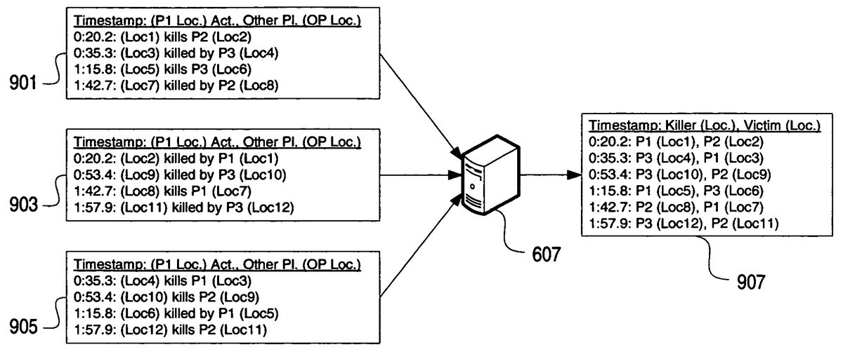
Upon receiving the game session telemetry data, in step705the process server607analyzes the game session telemetry data and combines the game session telemetry data from each game console into a single game session file, removing redundancy where possible. For example, each kill may be reported twice, once by the player character performing the kill, and once by the player character that was killed. Thus, the process server607matches the reported pairs and records the kill in a single entry in the game session file.FIG. 9conceptually illustrates redundancy removal performed by process server607after receiving recorded game data from three game consoles participating in a three-player two-minute Slayer type multiplayer game. InFIG. 9, process server607receives three game session telemetry data files901,903,905, one from each participating game console, corresponding to player 1 (P1), player 2 (P2), and player 3 (P3), respectively. Process server607analyzes the data files, confirms that all data appears accurate (e.g., timestamps and kills match—player 3 should not report an extra kill when neither player 1 nor player 2 report having been killed that extra time), and outputs the processed data907. Processed data907includes, for example, a timestamp of an event, and the event data. Here, the event data includes an identification of a player character that killed another player character, the location of the killing player character at the indicated time, an identification of the killed (victim) player character, and the location of the killed player character at the indicated time. The single game session file907may further include objective data, e.g., bomb or flag carrying information, when the multiplayer game type so provides.
While a single game session file is illustrated herein, the game session telemetry data need not ever actually be stored in a single file, but rather may be stored in multiple files or directly stored in database611. Alternatively, database server611may store each game session as a stream of data corresponding to a game session, e.g., where queries are expected to be based on game sessions. In a system where queries may be based on user, map, weapon, or some other criteria, the game session telemetry data may be indexed by additional or other fields instead of by game session. For example, data may be indexed by map or by user to make queries based on map or user more efficient.
Referring back toFIG. 7, in step707the process server607stores the processed game session telemetry data807in database server611, and the method then waits until a user submits a query in step709. The query may be transmitted as a web services request, and may originate through a web server such as web server609. Web server609may host a web site (FIGS. 11-20, described below) through which a user can navigate to receive and review post-game statistics, strategy, and analysis. The user query may identify a game session for which strategy analysis is desired. The game session may identify a map or virtual environment in which the identified game session was played, which is used to depict the post game analysis. Other query data may optionally be provided, e.g., a location or perspective from which the game analysis should be graphically depicted, and/or a user ID corresponding to one of the players that participated in the queried game session. If no location or perspective is provided, a default may be used.
In step711, based on the received query, the database server611returns the stream of data corresponding to queried game session, and web server609analyzes the data for the identified game session and places the location information in a two-dimensional view selected for display to the user. The two-dimensional view may be based on the location or perspective selected by the user, or may be a default or predetermined location or perspective. Once the location information is placed within the two-dimensional view, the web server609serves the graphic to the user in step713for display on the user's computer615, e.g., in a web browser application window.
FIG. 10illustrates a sample method through which database server611and/or web server609may convert the recorded three dimensional location information into two-dimensional position information on a two-dimensional image. In step1001a game developer, administrator of title server613, a player, or some other individual selects a view from which post-game analysis should be provided. The view may be selected based on a specific location in the virtual environment depicted within the view, based on strategic importance of a location within the view, or any other criteria. Step1003sets a camera location, view, and orientation within the virtual environment based on the desired view. In step1005a projection matrix for the view is created, and in step1007a 2-dimensional image of the view based on the camera location and the projection matrix is composited. The database server611or web server609stores the two-dimensional image with corresponding metadata whereby three-dimensional points can later be inserted or drawn into the two-dimensional image.
At some later time, in step1009database server611receives a query from a user for strategic analysis of a selected game session. As a result, in step1011the database server611, using the stored metadata, calculates where the queried location information is located within the two-dimensional view, and in step1013the database server611saves a composite image of the selected view with the location information for the queried game session overlaid on the image. Finally, in instep1015, the database server sends the composite image to the web server609for further delivery to the user. Those of skill in the art will appreciate that each step ofFIG. 10may be performed at any time, provided steps1001-1007are performed prior to steps1011-1015. Where a system is capable of rendering screenshots in real-time (e.g., using saved films and/or a farm of game consoles dedicated to this purpose), a user may specify details about the screenshot she would like to see or have the screenshot itself generated from the saved film and aggregate data.
Those of skill in the art will appreciate that variations and modifications to the method ofFIG. 10may be created and/or performed. For example, according to an illustrative aspect, a developer in step1001may manually navigate a game level or map with a debug camera and pick locations in step1003which would provide interesting points of view for various locations on the map during a game. The developer in step1005may run a command or execute a utility which takes a screenshot, stores depth information (z-buffer), and the camera information and saves it into a package in step1007. The relevant camera information may include the world to view matrix, the projection matrix, the viewport bounds and the far clipping distance, among other information. With this information, a world point can be projected into 2D screen space in step1011by multiplying the world point by the world to view matrix to get the world point into camera space and then by the projection matrix to transform the world point into screen space. The system may scale and translate the resulting point to get the resulting point into the viewport and then scale and translate the resulting point into image space using viewport bounds.
The system in step1013may draw or render each point in image space using a 2D method and overlay it over the source image. Additionally, the depth information (z-buffer) can be used to determine if a point is obscured or behind visible geometry. If an item is so obscured it may be displayed in a different way, such as with a dotted line or different color.
FIGS. 11-20illustrate screenshots of web site pages that may be used to allow a user to navigate for and review requested post-game strategy information. After optionally logging in to the web site or otherwise identifying him- or herself, the web server609may display a PlayerStats screen1101to the user, on which a selectable tab1102displays a list of games1103selectable by the user for review and analysis. Tab1102may display basic information regarding each game, e.g., a game type, date/time, map name, and the player's final position at the end of the game (e.g., 1st, 2nd, 3rd, etc.).
Upon selecting a specific game session, e.g., game1105, the web server609may serve a GameStats screen1201as illustrated inFIG. 12, through which the user can navigate to review post-game statistics from the post-game carnage report (PCR). GameStats screen1201may provide multiple tabs1203,1205,1207,1209, and1211through which a user can review overall stats, kills, player versus player information, medals (achievements), and hits, respectively.FIG. 12illustrates a GameStats screen when Stats tab1203is selected by the user, and also represents an optional default view when the GameStats screen is selected.FIG. 13illustrates a GameStats screen when Kills tab1205is selected by the user.FIG. 14illustrates a GameStats screen when P.v.P (player versus player) tab1207is selected by the user.FIG. 15illustrates a GameStats screen when Medals (achievements) tab1209is selected by the user.FIG. 16illustrates a GameStats screen when Hits tab1211is selected by the user.
Referring back toFIG. 12, GameStats screen1201may include a link to a GameViewer1213, through which the user can access the recorded game data stored in database server611. Upon selection of GameViewer link1213, web server609sends a query request to database server611for the default view for the game session corresponding to game1105(FIG. 11). Database server611pulls the stored two-dimensional image of the default view (from step1007, above), performs steps1011and1013of the method ofFIG. 10, and sends the composite image to web server609. With reference toFIG. 17, web server609then displays GameViewer screen1701, which includes the composite image1703. Composite image1703depicts an overhead overview of the HALO® 2 map entitled “Ascension.” Composite image1703provides strategic information to the user, including a timeline1723of the game session indicating position and movement information, and information indicating which players killed which other players and a relative time into the game of the kill. Timeline1723may include various identifications of killers and victims, e.g., including a shield corresponding to each player in the appropriate location (i.e., killer or victim) at each occurrence. For example, shield1725may correspond to the player having the gamertag “Aviator,” and a second shield1727may correspond to the player having the gamertag “SChang1038.”
Composite image1703may also provide information regarding locations of each kill, as well as the weapon used for the kill. In composite image1703, each arrow represents a kill. Each arrow originates from a shield image corresponding to a killer player character and terminates at a shield image corresponding to a victim player character. The composite image1703may further include a weapon icon1731indicating a weapon used by the killer to kill the victim. For example, weapon icon1731indicates a rocket launcher, weapon icon1733indicates a machine gun, and weapon icon1735indicates a sniper rifle. Other weapon icons may be used to indicate other weapons. Thus, for example, arrow1729indicates that, using the sniper rifle from the red base, SChang1038killed Aviator, who was located in the dish when killed.
GameViewer screen1701may also include one or more icons1705,1707,1709,1711,1713,1715,1717, and1719, each corresponding to another viewpoint or perspective from which the user can review and analyze the recorded game data. Each icon may include a graphical depiction of the viewpoint and/or a name of the location the viewpoint represents or views. A presently selected view may be highlighted1721. Upon selection of any icon, web server609sends a query request to database server611for the selected view for the game session. Database server611pulls the stored two-dimensional image of the selected view (from step1007, above), performs steps1011and1013of the method ofFIG. 10, and sends the composited image to web server609. For example, upon selection of icon1705, GameViewer screen1701is displayed. Upon selection of icon1707, web server609displays a second GameViewer screen1801(FIG. 18).
FIG. 18illustrates GameViewer screen1801, which includes a composite image1803depicting a view from the Banshee Platform in the map entitled “Ascension.” A user can enlarge a portion of the composite image by selecting a location on the image. For example, if the user selects location1805on composite image1803, web server609displays GameViewer screen1901(FIG. 19), which includes composite image1903. Composite image1903is an enlarged view of composite image1803, centered on location1805.
As discussed above, the recorded game information may include location information regarding paths that players took to complete an objective in some multiplayer games.FIG. 20illustrates a gameviewer screen2001corresponding to game1107on screen1101(FIG. 11). As seen inFIG. 20, upon selecting an Objective Route link2003, web server requests from database server611and displays composite image2005. Composite image2005depicts a view from the southwest corner of a map entitled “Colossus.” Composite image2005depicts a path2007over which a player2009carried the flag and successfully returned the flag to her home base at location2011.
The above description of various illustrative features and aspects of a post-game GameViewer are illustrative, and various modifications and variations are possible. For example, according to one variation, database server611may store and index kill information by gamertag (player ID), instead of or in addition to indexing by game session. A user, via web server609, may request a composite view of a map, e.g., Ascension, using kill data for a single gamertag, e.g., Aviator. The database server611may then obtain all kill information (kills and deaths) for the selected player, and place the kill locations on a background composite image (e.g., the default overview overhead image), and serve the composite image to the web server609for display to the user. The composite image may thus provide an indication of locations in which Aviator was killed most often, as well as locations from which Aviator had the most kills. Instead of a timeline, the composite image may optionally provide a summary of weapons used for each kill and death. The user having gamertag Aviator may analyze the data to determine how to modify his own game play so as to avoid falling into a predictable pattern. Other users may request and analyze Aviator's data to research Aviator's style of play and determine his movement patterns and habits, e.g., always sniping from the highest location on a map.
In another variation, database server611may store and index information by map. A user, via web server609, may request a composite view of a map, e.g., Ascension, for some pre- or user-defined set of players. The database server611may then obtain all kill information (kills and deaths) for the selected players and map, and place the kill locations on a background composite image (e.g., the default overview overhead image), and serve the composite image to the web server609for display to the user. For example, a user might request a composite image based on all players who have ever played a particular map, thus obtaining a composite image providing overall strategic analysis for the map based on general user trends. The user can thus learn how best to play the map when playing against a random assortment of other gamers.
Alternatively, a user could request a composite image based on all players within a predefined group, team, club, clan, or other allied group of users. Groups, clubs, teams, clans, and the like are known in the art and need not be discussed separately at length here. Thus, if a player in a clan has an upcoming match against another clan, that player can request a composite image based on the opponent clan's members, selecting a map on which the upcoming match might be played. The player can then analyze which locations the opponent clan's members hide, wait, and avoid. As a result of the pre-game analysis, the player and his or her clan may alter their strategy based on the expected strategy of the opponent clan.
In another illustrative variation, where the game session telemetry data includes a saved film (FIG. 8B), database server611may recreate the multiplayer game using a game engine application also stored on the database server611or on some other connected device, and output the game to a virtual video output port through which an MPEG, AVI, MOV or other multimedia and/or movie file may be captured based on the output. The game engine may maintain a constant camera position and angle, or rotate through a series of preset camera positions and angles to highlight various areas. The multimedia file is sent to web server609for further distribution to a requesting user, whereby the user can review the generated movie of the game session. Alternatively, the saved film can be converted into XML X3D and/or Virtual Reality Modeling Language (VRML) data, the standards for which are publicly known at www.web3d.org. A user can then navigate, or “fly,” around the virtually depicted environment via a web page served by web server609.
In yet another illustrative variation, instead of the user only being able to select from a predetermined set of views (e.g., view1705-1719ofFIG. 17), the user can place a camera in any position and angle in a map, send the camera placement information to the database server611, and the database server611compiles a composite image based on the user-defined camera location and angle, e.g., using a game engine to render the initial 2D view, then add the location information as described above.
Thus, using the above-described game data collection, reporting, and viewer, users can review and analyze game data and strategy after a game has ended. Users are able to review their own strategy as well as strategies used by other players. In addition, the above described system and methods can be used to detect cheating on an online gaming network. Database server611, or some other server, may analyze the recorded data, including the flag and bomb carrying data, and compare the data against the coded laws of physics in the game engine to determine whether the movements are valid. That is, the video game might adhere to laws of physics similar to those known to exist in reality, or the video game might adhere to different physics, e.g., different gravity, acceleration, thrust, force, etc. Thus, if a player carrying the flag moves halfway across a map in one second, and the database server knows, based on the physics of the game engine, that a player cannot move that far in one second, the database server may determine that the player carrying the flag is cheating. The database server611may notify the online gaming network of the player's cheater status for further action against the user.
The database server611may also notify a matching server within the title server, thus preventing the user from being matched into multiplayer games for that game title. The database server611may also notify web server609of the player's cheater status. If a user having a gamertag identified as a cheater tries to log into the web site served by web server609, the web server may store a cookie on that player's PC615, identifying the owner of that PC as a cheater. The web server may then prevent any user from logging in to the web site via that PC. If the user tries to log in under a different name, the web server609will still detect the cookie, and continue to prevent the user from accessing the web site, regardless of the login name the user attempts to use.
Illustrative aspects may be applied to both single-player and/or multi-player games. For example, a player may use the GameViewer to analyze problem locations for that player in a single-player mode of a game, to identify where enemies are hiding or from where enemies are killing the single player. Those of skill in the art will appreciate that various inputs, functions, modules, procedures, servers, and/or other mechanisms may be used to perform features described herein. The present application includes any novel feature or combination of features disclosed herein either explicitly or any generalization thereof. While the features have been described with respect to specific examples including presently preferred modes of carrying out the invention, those skilled in the art will appreciate that there are numerous variations and permutations of the above described systems and techniques. Thus, the spirit and scope of the invention should be construed broadly as set forth in the appended claims.
Claims
- In a computing network which includes one or more game consoles connectable to a secure private network on which players of an online video game can log on for purposes of playing the online video game and competing with one another, one or more computer-readable media storing computer-executable instructions for performing a method for collecting player telemetry data while the game is played and for analyzing the telemetry data recorded during a game session so that less skilled players have an opportunity to research tactics of more advanced players, wherein said video game comprises a simulated environment in which the game is played, and said telemetry data comprises location information corresponding to one or more events occurring within the simulated environment, and wherein said method is comprised of steps for: at one or more of the player consoles, recording game session telemetry data by either recording at least timestamp and location data for one or more predefined events which occur while the video game is being played, or recording player inputs and periodically recording checkpoints which include all video game state data at the instant of each checkpoint;once the video game is completed, automatically uploading to the secure private network the recorded game session telemetry data from the one or more player consoles at which the telemetry data was recorded, said game session telemetry data corresponding to at least a first player-character controlled by one of the players using one of said player consoles during the game session;at the secure network, analyzing the game session telemetry data received from all player consoles at the conclusion of the game session so as to combine the game session telemetry data from each game console into a single game session file and so as to remove redundant telemetry data where possible;storing the analyzed game session telemetry data in a database at the secure private network;at least one of the players of the game session sending to the secure private network a query regarding how a particular feat by one of the other players was accomplished, and said private network thereafter querying the database for telemetry data matching the query;and the private network generating a two dimensional image comprising a first view of the simulated environment overlaid with the queried telemetry data, wherein the overlaid telemetry data is placed in the two dimensional image at an approximate location of each event to which the overlaid telemetry data corresponds so that the query can be viewed and analyzed by the player submitting the query.
- In a computing network which includes one or more game consoles connectable to a secure private network on which players of an online video game can log on for purposes of playing the online video game and competing with one another, a method for collecting player telemetry data while the game is played and for analyzing the telemetry data recorded during a game session so that less skilled players have an opportunity to research tactics of more advanced players, wherein said video game comprises a simulated environment in which the game is played, and said telemetry data comprises location information corresponding to one or more events occurring within the simulated environment, and wherein said method is comprised of steps for: at one or more of the player consoles, recording game session telemetry data by either recording at least timestamp and location data for one or more predefined events which occur while the video game is being played, or recording player inputs and periodically recording checkpoints which include all video game state data at the instant of each checkpoint;once the video game is completed, automatically uploading to the secure private network the recorded game session telemetry data from the one or more player consoles at which the telemetry data was recorded, said game session telemetry data corresponding to at least a first player-character controlled by one of the players using one of said player consoles during the game session;at the secure network, analyzing the game session telemetry data received from all player consoles at the conclusion of the game session so as to combine the game session telemetry data from each game console into a single game session file and so as to remove redundant telemetry data where possible;storing the analyzed game session telemetry data in a database at the secure private network;at least one of the players of the game session sending to the secure private network a query regarding how a particular feat by one of the other players was accomplished, and said private network thereafter querying the database for telemetry data matching the query;and the private network generating a two dimensional image comprising a first view of the simulated environment overlaid with the queried telemetry data, wherein the overlaid telemetry data is placed in the two dimensional image at an approximate location of each event to which the overlaid telemetry data corresponds so that the query can be viewed and analyzed by the player submitting the query.
- A method as defined in claims 1 or 2 wherein the one or more predefined events comprises a first player character killing a second character in the simulated environment of the video game, and wherein the overlaid telemetry data indicates an identity of a killer and an identity of a victim.
- A method as defined in claim 3 , wherein the game session telemetry data further comprises a weapon used by the first player character to kill the second character, and wherein the overlaid telemetry data further comprises an indication of the weapon used.
- A method as defined in claim 3 , wherein the second character compnses a second player character.
- A method as defined in claims 1 or 2 wherein the query comprises a map.
- A method as defined in claims 1 or 2 wherein the query comprises an identification of an allied group of users.
- A method as defined in claims 1 or 2 wherein the one or more predefined events comprises the player character carrying an object usable in the video game to complete an objective.
- The method of claim 8 , wherein the telemetry data comprises a location of the player character, determined at least once for a predetermined amount of time, while the player character is carrying the object usable in the video game to complete the objective.
- A method as defined in claims 1 or 2 wherein the game session telemetry data corresponds to a player-character, said player-character controlled by a user of a game console, and said game session telemetry data comprising location information over time, each location corresponding to one or more events occurring during the game session.
- A method as defined in claim 10 further comprising steps for comparing the stored game session telemetry data against the physics of a game engine of the video game;and determining that a user corresponding to the telemetry data is a cheater when the stored game session telemetry data is adverse to the physics of the game engine.
- A method as defined in claim 10 wherein the game session telemetry data comprises location information over time as the player character carries an object usable in the video game to complete an objective.
- A method as defined in 11 further comprising steps for detecting when the user is attempting to log in to a web server;and when the user has been determined to be a cheater, causing a cookie indicating a cheater status to be stored on a computer corresponding to the user.
- A method as defined in claim 13 further comprising steps for checking for the presence of the cookie on a computer attempting to log in to the web site;and when the cookie is present, preventing anyone from logging in to the web site from the computer on which the cookie is stored.
Disclaimer: Data collected from the USPTO and may be malformed, incomplete, and/or otherwise inaccurate.