U.S. Pat. No. 7,486,868
LIGHT-EMITTING FIBERS INTERTWINED IN GRASS RELATED TO A PLAYER'S OR GAME OBJECT'S POSITION
AssigneeInternational Business Machines Corp
Issue DateAugust 1, 2007
Illustrative Figure
Abstract
A method, system and computer program product for improving accuracy and experience of a game. Signals are sent from a computer system to appropriate sensors based on a player's or game object's position to activate connected light-emitting fibers that are blended with grass on a playing field. The light-emitting fibers are activated in such a manner to display light to indicate an infraction (e.g., a player was in an offside position), a successful play (e.g., team made a first down), appropriate maneuvers, boundaries for a play, etc., thereby ensuring the game is fair and accurate and enhancing the experience of the game.
Description
DETAILED DESCRIPTION The present invention comprises a method, system and computer program product for improving accuracy and experience of a game. In one embodiment of the present invention, signals are sent from a computer system to appropriate sensors based on a player's or game object's position to activate connected light-emitting fibers that are blended with grass on a playing field. The light-emitting fibers are activated in such a manner as to display light to indicate an infraction (e.g., a player was in an offside position), a successful play (e.g., team made a first down), appropriate maneuvers, boundaries for a play, etc., thereby ensuring the game is fair and accurate and enhancing the experience of the game. While the following discusses the present invention in connection with sports, the principles of the present invention may be applied to other events, such as half-time shows for a band or a dance team. For example, dynamic lines may be displayed on the playing field indicating where particular band or dance team members need to be on the field. The principles of the present invention may be applied to any event that uses a field. Further, a person of ordinary skill in the art would be capable of applying the principles of the present invention to any event that uses a playing field. Further, embodiments covering such permutations would fall within the scope of the present invention. In the following description, numerous specific details are set forth to provide a thorough understanding of the present invention. However, it will be apparent to those skilled in the art that the present invention may be practiced without such specific details. In other instances, well-known circuits have been shown in block diagram form in order not to obscure the present invention in unnecessary detail. For the most ...
DETAILED DESCRIPTION
The present invention comprises a method, system and computer program product for improving accuracy and experience of a game. In one embodiment of the present invention, signals are sent from a computer system to appropriate sensors based on a player's or game object's position to activate connected light-emitting fibers that are blended with grass on a playing field. The light-emitting fibers are activated in such a manner as to display light to indicate an infraction (e.g., a player was in an offside position), a successful play (e.g., team made a first down), appropriate maneuvers, boundaries for a play, etc., thereby ensuring the game is fair and accurate and enhancing the experience of the game.
While the following discusses the present invention in connection with sports, the principles of the present invention may be applied to other events, such as half-time shows for a band or a dance team. For example, dynamic lines may be displayed on the playing field indicating where particular band or dance team members need to be on the field. The principles of the present invention may be applied to any event that uses a field. Further, a person of ordinary skill in the art would be capable of applying the principles of the present invention to any event that uses a playing field. Further, embodiments covering such permutations would fall within the scope of the present invention.
In the following description, numerous specific details are set forth to provide a thorough understanding of the present invention. However, it will be apparent to those skilled in the art that the present invention may be practiced without such specific details. In other instances, well-known circuits have been shown in block diagram form in order not to obscure the present invention in unnecessary detail. For the most part, details considering timing considerations and the like have been omitted inasmuch as such details are not necessary to obtain a complete understanding of the present invention and are within the skills of persons of ordinary skill in the relevant art.
FIGS.1A-B—Game Field Implementing Grass Blended With Fiber Optic Blades
FIG. 1Aillustrates an embodiment of the present invention of a game playing field100(e.g., soccer field, football field) where field100is divided into “trays”101A-X that may be square shaped. Trays101A-X may collectively or individually be referred to as trays101or tray101, respectively. It is noted that trays101may be configured in a different shape than a square and thatFIG. 1Ais illustrative. Further, field100may include any number of trays101(e.g., 1,750 trays) that are interconnected with each other. Each tray101may include thousands of blades of grass102(e.g., polyethylene grass), blended with light-emitting fibers103(e.g., optical fibers), that reflect light upwards from tray101as illustrated inFIG. 1B.
FIG. 1Billustrates one of the thousands of blades of grass102in tray101in accordance with an embodiment of the present invention. Referring toFIG. 1B, each blade of grass102may be positioned in or on the soil104or other material. A portion of or all of the thousands of blades of grass102in tray101may each be blended with a light-emitting fiber103. Light-emitting fiber103may be connected to a sensor105configured to detect the obscuring of light thereby indicating the movement of a ball or a player passing light-emitting fiber103. Sensor105may further be configured to activate the connected light-emitting fiber103thereby allowing light-emitting fiber103to provide light of a certain color (including white light). Each sensor105may be connected to a computer106configured to control the activation of light-emitting fibers103in each tray101in field100as discussed further below in connection withFIGS. 3-5. A more detail discussion of computer system106is provided below in connection withFIG. 2.
FIG.2—Computer System
FIG. 2illustrates an embodiment of a hardware configuration of computer system106(FIG. 1B) which is representative of a hardware environment for practicing the present invention. Computer system106may have a processor201coupled to various other components by system bus202. An operating system203may run on processor201and provide control and coordinate the functions of the various components ofFIG. 2. An application204in accordance with the principles of the present invention may run in conjunction with operating system203and provide calls to operating system203where the calls implement the various functions or services to be performed by application204. Application204may include, for example, a program for improving the accuracy and experience of a game by implementing fiber optic field technology as discussed further below in association withFIGS. 3-5.
Referring toFIG. 2, read-only memory (“ROM”)205may be coupled to system bus202and include a basic input/output system (“BIOS”) that controls certain basic functions of computer system106. Random access memory (“RAM”)206and disk adapter207may also be coupled to system bus202. It should be noted that software components including operating system203and application204may be loaded into RAM206, which may be computer system's106main memory for execution. Disk adapter207may be an integrated drive electronics (“IDE”) adapter that communicates with a disk unit208, e.g., disk drive. It is noted that the program for improving the accuracy and experience of a game by implementing fiber optic field technology, as discussed further below in association withFIGS. 3-5, may reside in disk unit208or in application204.
Referring toFIG. 2, computer system106may further include a communications adapter209coupled to bus202. Communications adapter209may interconnect bus202with a network (e.g., local area network (“LAN”), wide area network (“WAN”)) to allow computer system106to communicate with sensors105(FIG. 1B).
Computer system106may further include a radio frequency identification receiver210(indicated as “RFID RXVR” inFIG. 2) configured to receive data sent from a radio frequency identification (“RFID”) chip or tag that may be placed on an object (e.g., soccer ball), on a player or in a player's equipment (e.g., football helmet, player's shoe). The RFID chip or tag stores data that may be thought of as an “electronic label” or a “code plate” that uniquely identifies items or players. Hence, upon RFID RXVR210receiving radio frequency identification tag data, application204may be configured to read the tag data and determine the object (e.g., soccer ball) or player (e.g., Joe Smith) associated with the tag data.
In connection with receiving the tag data, computer system106may further receive geographic information via a geographic data receiver211(indicated as “Geographic Data RXVR” inFIG. 2). The geographic information may include global positioning system (“GPS”) data from a GPS receiver which may be placed inside a ball (e.g., football, soccer ball) or on a player or in a player's equipment (e.g., football helmet, player's shoe). As is commonly known in the art, the GPS receiver uses triangulation to determine its location. The GPS receiver may relay position data to geographic data receiver211, such as by using the NMEA 0183 protocol. Upon receiving the position data along with the tag data, computer system106is able to determine the position of the ball or the identified player on field100(FIG. 1A).
Referring toFIG. 2, input/output (“I/O”) devices may also be connected to computer system106via a user interface adapter222and a display adapter236. Keyboard224, mouse226and speaker230may all be interconnected to bus202through user interface adapter222. Data may be inputted to computer system106through any of these devices. A display monitor238may be connected to system bus202by display adapter236. In this manner, a user is capable of inputting to computer system106through keyboard224or mouse226and receiving output from computer system106via display238or speaker230.
The various aspects, features, embodiments or implementations of the invention described herein can be used alone or in various combinations. The methods of the present invention can be implemented by software, hardware or a combination of hardware and software. The present invention can also be embodied as computer readable code on a computer readable medium. The computer readable medium is any data storage device that can store data which can thereafter be read by a computer system. Examples of the computer readable medium include read-only memory, random access memory, CD-ROMs, flash memory cards, DVDs, magnetic tape, optical data storage devices, and carrier waves. The computer readable medium can also be distributed over network-coupled computer systems so that the computer readable code is stored and executed in a distributed fashion.
As stated in the Background Information section, technology is playing an important role in sports, whether applied to an athlete's health, the athlete's technique, equipment's characteristics or even ensuring a fair game. For example, a system referred to as “instant replay” has been implemented in several sports (e.g., football, hockey, college football, basketball, tennis, rugby, etc.) where plays in a sporting match can be reviewed (or replayed) using recorded video feeds of the sporting match in order to ensure that the correct call is made on the play. However, instant replay is usually limited to being used in certain situations. Hence, many calls are still subject to human error. Further, even with instant replay, mistakes may still occur as usually a referee, a replay judge, etc., can only overturn a call if the call is clearly in error. Hence, a call may be incorrect but if there is not enough evidence to show the call to be clearly incorrect, the call will stand. Recently, a synthetic turf system used on a game field has been developed that includes blades of polyethylene grass blended with light-emitting fibers with the capability of reflecting light upwards. The fiber-optical laden blades are supposed to have the same look, feel and durability as non-illuminated blades. This system is commonly being referred to as “Turf TV” as the fiber-optical blades can be used to display team logos and even commercial viewing. As technology continues to play an important role in sports, it would be desirable if this fiber optic field technology could be used to ensure the game is even more fair and accurate than under the current system of instant replay thereby enhancing the experience of the game. The fiber optic field technology, as discussed in connection withFIGS. 1A-B, is used to ensure the game is more fair and accurate than the current system of instant replay as discussed further below in connection withFIGS. 3-5.FIG. 3is a flowchart of a method for drawing dynamic lines on field100(FIG. 1A) to indicate an appropriate distance from an object (e.g., soccer ball) on field100to begin a play (e.g., direct free kick in soccer).FIG. 4is a diagram illustrating appropriate light-emitting fibers103being activated in a manner that displays a circle around a soccer ball with a radius of ten yards, where a “direct free kick” in soccer requires the opponents to be beyond ten yards from the location of the soccer ball.FIG. 5is a flowchart of a method for drawing dynamic lines on field100to highlight an infraction, a successful play, etc. based on game rules.
FIG.3—Method for Drawing Dynamic Lines on the Playing Field to Indicate an Appropriate Distance From an Object
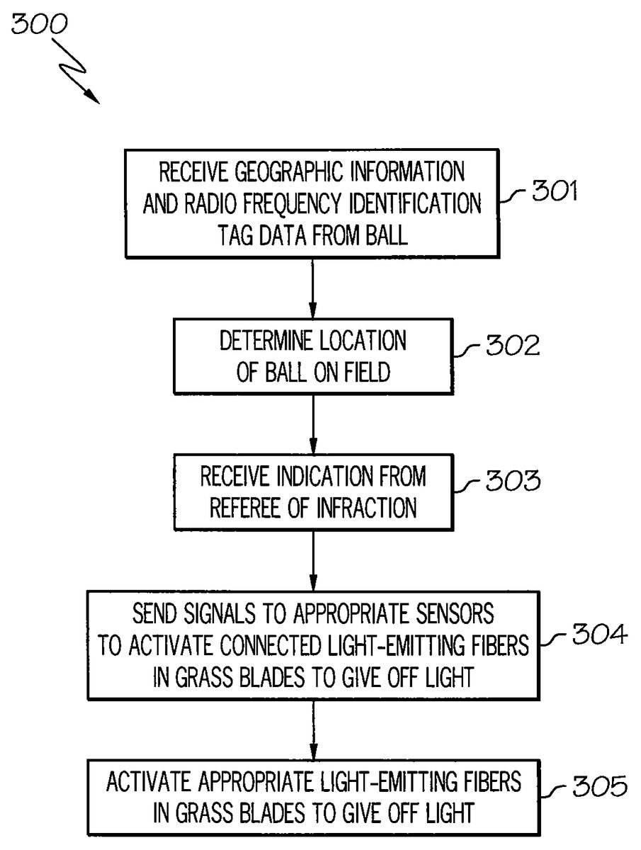
FIG. 3is a method300for drawing dynamic lines on field100(FIG. 1A) to indicate an appropriate distance from an object (e.g., soccer ball) in accordance with an embodiment of the present invention.
Referring toFIG. 3, in conjunction withFIGS. 1-2, in step301, computer system106receives geographic information and radio frequency identification tag data from a ball on field100. For example, the ball (e.g., soccer ball) may be equipped with both a global positioning system receiver and a radio frequency tag as illustrated inFIG. 4. Referring toFIG. 4,FIG. 4is a diagram illustrating appropriate light-emitting fibers103being activated in a manner that displays a circle around a soccer ball401in accordance with an embodiment of the present invention. As illustrated inFIG. 4, soccer ball401may be equipped with a GPS receiver402and a RFID tag403. Both GPS receiver402and RFID tag403may be configured to transmit geographic and radio frequency identification tag data, respectively, to computer system106.
Returning toFIG. 3, in conjunction withFIGS. 1-2, in step302, computer system106determines the location of the ball on field100based on the geographic information received from the ball in step301. Further, computer system106identifies the ball based on the received radio frequency identification tag data in step301thereby associating the received geographic information with the ball.
In step303, computer system106receives an indication from a referee, directly or indirectly, of an infraction. For example, computer system106may receive an indication of a foul (e.g., pushing, tripping) in the game of soccer thereby necessitating awarding the opposing team a “direct free kick.” For a direct free kick, the soccer ball should be stationary and opponents must remain ten yards from the ball until the ball is in play.
In step304, computer system106sends signals to appropriate sensors105to activate connected light-emitting fibers103in grass blades102to give off light. For example, computer system106, after determining the location of the ball in step302, may send signals to appropriate sensors105that are located ten yards from the ball to activate those connected light-emitting fibers103to give off light.
In step305, the appropriate light-emitting fibers103in grass blades102are activated to give off light. For example, referring toFIG. 4, computer system106, after determining the location of soccer ball401in step302, may send signals to appropriate sensors105that are located ten yards from ball401to activate those connected light-emitting fibers103to give off light thereby displaying a lighted circle404with a radius often yards from soccer ball401. By displaying lighted circle404, referees can accurately determine if an opposing player is within ten yards from soccer ball401thereby ensuring the game is fair and accurate and enhancing the experience of the game. It is noted that the line, circle, etc., may be displayed for a specified duration of time or until the game or field condition or information has been updated or changed.
WhileFIG. 3was discussed in connection with an example of a direct free kick in soccer, the principles of the present invention ofFIG. 3may be applied to other sports and other infractions where a location from the game playing object (e.g., football) is important in ensuring the game is fair and accurate. It is noted that a person of ordinary skill in the art would be capable of applying the principles of the present invention ofFIG. 3to other sports and other infractions where a location from the game playing object is important in ensuring the game is fair and accurate. Further, embodiments covering such permutations would fall within the scope of the present invention.
Further, whileFIG. 3was discussed in connection with an example of a direct free kick in soccer, the principles of the present invention ofFIG. 3may be applied to determining the location of any game playing object (e.g., baseball bat). It is noted that a person of ordinary skill in the art would be capable of applying the principles of the present invention ofFIG. 3to determining the location of any game playing object (e.g., baseball bat). Further, embodiments covering such permutations would fall within the scope of the present invention.
Method300may include other and/or additional steps that, for clarity, are not depicted. Further, method300may be executed in a different order presented and that the order presented in the discussion ofFIG. 3is illustrative. Additionally, certain steps in method300may be executed in a substantially simultaneous manner or may be omitted.
A method for drawing dynamic lines on field100to highlight an infraction, a successful play, etc. based on game rules is now discussed below in association withFIG. 5.
FIG.5—Method for Drawing Dynamic Lines on the Playing Field to Indicate an Infraction, Successful Play, etc. Based on Game Rules
FIG. 5is a method500for drawing dynamic lines on field100(FIG. 1A) to indicate an infraction, a successful play, etc. based on game rules.
Referring toFIG. 5, in conjunction withFIGS. 1-2, in step501, computer system106receives geographic information and radio frequency identification tag data from a player on field100. For example, the player's equipment (e.g., helmet, shoe) may be equipped with both a global positioning system receiver and a radio frequency tag. Both the global positioning system receiver and the radio frequency tag may be configured to transmit geographic and radio frequency identification tag data, respectively, to computer system106.
In step502, computer system106determines the location of the player on field100based on the geographic information received from the player in step501. Further, computer system106identifies the player based on the received radio frequency identification tag data in step501thereby associating the received geographic information with the player. In addition to determining the location of the player on field100, computer system106may determine the orientation of the player based on multiple geographic data received from the player over a period of time. For example, computer system106may determine that the player is running in a northwest manner based on multiple received geographic data from the player.
In step503, computer system106receives geographic information and radio frequency identification tag data from a ball on field100. For example, a football may be equipped with both a global positioning system receiver and a radio frequency tag. Both the global positioning system receiver and the radio frequency tag may be configured to transmit geographic and radio frequency identification tag data, respectively, to computer system106.
In step504, computer system106determines the location of the ball on field100based on the geographic information received from the ball in step503. Further, computer system106identifies the ball based on the received radio frequency identification tag data in step503thereby associating the received geographic information with the ball.
In step505, computer system106determines dynamic lines on field100according to game rules. “Dynamic lines,” as used herein, refers to lines, circles, squares, etc., that are generated, but not displayed on field100, that indicate boundaries for an infraction, a successful play, etc. For example, computer system106may dynamically determine a line which indicates an offside position in soccer.
In step506, computer system106determines whether there are any infractions based on the game rules and the location of the players on field100. For example, computer system106determines whether a soccer player is in an offside position. If there is an infraction, then, in step507, computer system106sends signals to appropriate sensors105to activate connected light-emitting fibers103in grass blades102to give off light to highlight the infraction. For example, computer system106, after determining a player is in an offside position, may send signals to appropriate sensors105that are located at the offside position to activate those connected light-emitting fibers103to give off light.
In step508, the appropriate light-emitting fibers103in grass blades102are activated to give off light to highlight the infraction. For example, the light-emitting fibers103may be activated in a manner to highlight that a player was in an offside position. By displaying light on field100in a manner to indicate an infraction (e.g., a player was in an offside position), referees can accurately determine if an infraction has occurred thereby ensuring the game is fair and accurate and enhancing the experience of the game.
If, however, there was no infraction, then, in step509, computer system106determines whether there are any successful plays based on the game rules and the location of the players on field100. For example, computer system106determines whether the football past the first down line. If the football past the first down line, then, in step510, computer system106sends signals to appropriate sensors105to activate connected light-emitting fibers103in grass blades102to give off light to highlight the fact that the team made a first down. For example, computer system106, after determining a first down has been made, may send signals to appropriate sensors105that are located at the first down line to activate those connected light-emitting fibers103to give off light.
In step510, the appropriate light-emitting fibers103in grass blades102are activated to give off light to highlight the successful play. For example, the light-emitting fibers103may be activated in a manner to highlight that a team made a first down. By displaying light on field100in a manner to indicate a successful play (e.g., team made a first down), referees can accurately determine if a successful play has occurred thereby ensuring the game is fair and accurate and enhancing the experience of the game.
If, however, there was not a successful play, then computer system106receives additional geographic information and radio frequency identification tag data from a player on field100in step501.
WhileFIG. 5was discussed in connection with examples of displaying light to highlight infractions, such as being offside in soccer, or successful plays, such as making a first down in football, the principles of the present invention ofFIG. 5may be applied to other sports and other infractions or successful plays where an infraction or successful play is based on the position of a playing object and/or player(s). It is noted that a person of ordinary skill in the art would be capable of applying the principles of the present invention ofFIG. 5to other sports and other infractions or successful plays where an infraction or successful play is based on the position of a playing object and/or player(s). Further, embodiments covering such permutations would fall within the scope of the present invention.
Further, whileFIG. 5was discussed in connection with displaying light to indicate infractions or successful plays, the principles of the present invention ofFIG. 5may be applied to displaying light: to indicate the direction of a player; to guide an individual (e.g., a player, a band member) to perform a particular play, stance, orientation, etc., to improve their skills; to indicate a huddle, and so forth. It is noted that a person of ordinary skill in the art would be capable of applying the principles of the present invention ofFIG. 5to display light to indicate other aspects of the game other than infractions or successful plays. Further, embodiments covering such permutations would fall within the scope of the present invention.
Method500may include other and/or additional steps that, for clarity, are not depicted. Further, method500may be executed in a different order presented and that the order presented in the discussion ofFIG. 5is illustrative. Additionally, certain steps in method500(e.g., steps501and503; and steps502and504) may be executed in a substantially simultaneous manner or may be omitted.
Although the method, system and computer program product are described in connection with several embodiments, it is not intended to be limited to the specific forms set forth herein, but on the contrary, it is intended to cover such alternatives, modifications and equivalents, as can be reasonably included within the spirit and scope of the invention as defined by the appended claims. It is noted that the headings are used only for organizational purposes and not meant to limit the scope of the description or claims.
Claims
- A method for improving accuracy and experience of a game comprising the steps of: sending signals to appropriate sensors to activate appropriate light-emitting fibers blended with grass on a field;activating said appropriate light-emitting fibers to give off light;receiving geographic information from a game object;determining location of said game object on said field;and receiving an indication from a referee of an infraction;wherein said appropriate light-emitting fibers are activated to give off light in a manner that indicates an appropriate distance from said game object on said field.
- A method for improving accuracy and experience of a game comprising the steps of: sending signals to appropriate sensors to activate appropriate light-emitting fibers blended with grass on a field: activating said appropriate light-emitting fibers to give off light;and determining dynamic lines on said field according to game rules;wherein said signals are sent to said appropriate sensors to activate said appropriate light-emitting fibers to highlight one of the following: an infraction and a successful play.
- A method for improving accuracy and exerience of a game comprising the steps of: sending signals to appropriate sensors to activate appropriate light-emitting fibers blended with grass on a field;and activating said appropriate light-emitting fibers to give off light;wherein said signals are sent to said appropriate sensors to activate said appropriate light-emitting fibers to perform one or more of the following: guide an orientation of an individual, highlight a direction of a player, and highlight a huddle.
Disclaimer: Data collected from the USPTO and may be malformed, incomplete, and/or otherwise inaccurate.