U.S. Pat. No. 7,338,363
GAMING MACHINE, SERVER, AND PROGRAM
AssigneeUniversal Entertainment Corp
Issue DateOctober 17, 2003
Bot M8 LLC Asserts Sony’s PlayStation 4 “Uncharted” Game Infringes Its Patent, but Court Finds Bot M8’s Patent Invalid
Bot M8 LLC Asserts Sony’s PlayStation 4 “Uncharted” Game Infringes Its Patent, but Court Finds Bot M8’s Patent Invalid
Bot M8 LLC v. Sony Corporation of America et al
No. 3:19-cv-07027
United States District Court for the Northern District of California
Filed August 12, 2019

Sony Corporation of America (“Sony”) has been awarded summary judgment against Bot M8 LLC, which had sued Sony in 2019. Bot M8’s lawsuit alleged that Sony’s PlayStation 4 “Uncharted 4” and “Uncharted: the Lost Legacy” games infringed U.S. Patent No. 7,338,363 (“the ’363 Patent”) because they provided an unlockable weapon system allegedly comprising “specification values.” The Court found that Claim 1 of the ’363 Patent was directed to unpatentable subject matter.
In Alice Corp. v. CLS Bank Int’l et al., the Supreme Court created a two-part framework for subject matter eligibility. First, courts must determine whether a patent’s claims are directed to an abstract idea. Second, if a patent’s claims are directed to an abstract idea, courts are to determine whether a claim may be patentable despite being directed to an abstract idea.
With regard to the first inquiry, the Court characterized Claim 1 of the ’363 Patent as directed to an abstract idea. The Court particularly criticized the lack of detail in the claims of the ’363 Patent:
“At the most specific, claim 1 of the ’363 patent doesn’t actually teach how to increase or decrease the difficulty of a slot machine, or any gaming machine for that matter, based on prior results to keep players engaged. It only instructs a game operator to present new jackpot opportunities if the two slots players win enough and to take away jackpot opportunities if the two lose enough. Well, how?”
With regard to the second inquiry, the Court cited Mayo Collaborative Servs. v. Prometheus Labs, Inc., which provides that “the mere recitation of a generic computer cannot transform a patent-ineligible abstract idea into a patent-eligible invention.” The Court held that, although the ’363 Patent gives special names to generic computer parts (such as a “transmitting device” that transmits data and a “specification value determining device” that determines a specification value), the parts are still generic computer parts that perform conventional computing tasks.
In view of its decisions in both prongs of the Alice/Mayo two-part framework, the Court found that Claim 1 of the ’363 Patent was invalid under 35 U.S.C. § 101.
Illustrative Figure
Abstract
A slot machine is provided with specification value setting means for setting at least one specification value as a control condition when game control is carried out, total result data receiving means for receiving from a server the data of the total result of a game result achieved by a first gaming machine and a game result achieved by a second gaming machine, specification value determining means for determining the specification value on the basis of the data of the total result received by the total result data receiving means, and specification value renewing means for renewing the specification value set by the specification value setting means to the specification value determined by the specification value determining means. There is provided a slot machine for renewing the specification value on the basis of the total result of the game results achieved by the first and the second gaming machines.
Description
DETAILED DESCRIPTION OF THE PREFERRED EMBODIMENTS According to the present invention, a preferred embodiment will be described hereunder referring to the drawings. FIG. 1is a perspective view of a gaming machine according to the embodiment of the present invention. In the following embodiment, a slot machine to which the present invention is applied will be described as a preferable embodiment of the gaming machine according to the present invention. A housing12enclosing an outer periphery of a slot machine10comprises a main body11and a door13. A rectangular display window14is provided on the front face of the housing12which forms the whole body of the slot machine10. Three kinds of reels26L,26C,26R are freely rotatably provided in the housing12, and plural kinds of identification information pictures (i.e., symbols) are drawn on the outer peripheral surface of each reel. Each of the reels26L,26C,26R is provided so as to be visually recognized through the display window14. The identification information pictures (i.e., symbols) drawn on the outer peripheral surfaces of the reels26L,26C,26R are driven downward as the reels are rotated. When the rotation of each of the reels26L,26C,26R is stopped, three identification information pictures (i.e., symbols) drawn on the outer peripheral surface of each reel are visually recognizable through the display window14. A display device30is provided at the lower side of the display window14. The display device30comprises a liquid crystal display, for example. As described later, various images such as notification pictures for game contents, effect pictures for amusing game players, etc. are displayed on the display device30. Furthermore, a touch sensor56(seeFIG. 4) is provided on the display device30to enable various kinds of operations. A substantially horizontal seat portion28is provided at the lower side of the display device30. A medal slot31is provided on the right side of the upper face of the seat portion28. A medal, a token, ...
DETAILED DESCRIPTION OF THE PREFERRED EMBODIMENTS
According to the present invention, a preferred embodiment will be described hereunder referring to the drawings.
FIG. 1is a perspective view of a gaming machine according to the embodiment of the present invention. In the following embodiment, a slot machine to which the present invention is applied will be described as a preferable embodiment of the gaming machine according to the present invention.
A housing12enclosing an outer periphery of a slot machine10comprises a main body11and a door13. A rectangular display window14is provided on the front face of the housing12which forms the whole body of the slot machine10.
Three kinds of reels26L,26C,26R are freely rotatably provided in the housing12, and plural kinds of identification information pictures (i.e., symbols) are drawn on the outer peripheral surface of each reel. Each of the reels26L,26C,26R is provided so as to be visually recognized through the display window14. The identification information pictures (i.e., symbols) drawn on the outer peripheral surfaces of the reels26L,26C,26R are driven downward as the reels are rotated. When the rotation of each of the reels26L,26C,26R is stopped, three identification information pictures (i.e., symbols) drawn on the outer peripheral surface of each reel are visually recognizable through the display window14.
A display device30is provided at the lower side of the display window14. The display device30comprises a liquid crystal display, for example. As described later, various images such as notification pictures for game contents, effect pictures for amusing game players, etc. are displayed on the display device30.
Furthermore, a touch sensor56(seeFIG. 4) is provided on the display device30to enable various kinds of operations.
A substantially horizontal seat portion28is provided at the lower side of the display device30. A medal slot31is provided on the right side of the upper face of the seat portion28. A medal, a token, or a coin as a game medium may be inserted into the medal slot31for playing the game. By way of example, the medal is used in the following description. A 1-BET switch20for setting only one medal out of the inserted medals as a betting target for a game by one pushing operation is provided on the left side of the upper face of the seat portion28. In addition, a 2-BET switch22for setting only two medals out of the inserted medals as a betting target for the game is also provided. Furthermore, a maximum BET switch24for setting the permitted maximum number of medals out of the inserted medals as a betting target for the game is provided.
When the 1-BET switch20is operated by a game player, only a payline L1, which may be a prize-winning line, is set as a activated payline for determination of a game result (hereinafter, the activated payline will be referred to as “activated line”). When two or more medals have been already inserted and also the 2-BET switch22is operated by the game player, not only the payline L1, but also paylines L2A, L2B, that is, totally three paylines are set as activated lines.
Furthermore, when three or more medals have been already inserted and also the maximum BET switch24is operated by the game player, not only the paylines L1, L2A, L2B, but also paylines3A,3B, that is, totally five paylines are set as activated lines. However, when the number of residual medals out of the inserted medals is equal to two, only the three paylines L1, L2A, L2B out of the five paylines are activated. When the number of residual medals out of the inserted medals is equal to one, only the payline L1out of the five paylines is activated. With respect to the activated paylines, an indication thereof is displayed at a side of the display window14and notified to the game player.
A game start allowing state is set when a game player pushes the 1-BET switch20, the 2-BET switch22, or the maximum BET switch24.
As shown inFIG. 1, a start lever32is provided on the left side of the front face of the seat portion28so as to be operative by tilting. When the game player tilts the start lever32, the three reels26L,26C,26R start to rotate all at once. When the three reels26L,26C,26R are rotated, the identification information pictures (i.e., symbols) drawn on the outer peripheral surface of each of the reels26L,26C,26R are variably displayed.
When the rotational speeds of the three reels26L,26C,26R reach a predetermined speed, the game player is allowed to operate reel stop buttons34L,34C,34R as described later. However, the slot machine10may be configured without such stop buttons.
Three reel stop buttons34L,34C,34R which can be pushed are provided at the center on the front face of the seat portion28. The reel stop button34L is provided to stop the reel26L, the reel stop button34C is provided to stop the reel26C and the reel stop button34R is provided to stop the reel26R.
A payout button36is provided on the left side of the start lever32. When the game player pushes the payout button36, the inserted medals are paid out from a medal payout opening38at the lower portion on the front face of the housing12. The medals thus paid out are stored in a medal tray40.
Sound-transmissible portions42are provided on the upper side of the medal tray40to output sounds emitted from speaks (not shown) mounted in the housing12to the outside of the housing12.
As described above, a predetermined number of plural kinds of identification pictures (i.e., symbols), for example, twenty one identification pictures (i.e., symbols) are drawn on the outer peripheral surface of each of the reels26L,26C,26R. A predetermined number of medals are paid out and the current game condition is shifted to a more desirable game condition for the game player in accordance with the combination of identification information pictures (i.e., symbols) when each of the reels26L,26C,26R is stopped.
FIG. 3is a schematic diagram showing the internal construction of the housing of the slot machine10when the door13of the slot machine10is opened.
Various kinds of devices, various kinds of control boards (not shown) are contained in the slot machine10as shown inFIG. 3.
A setting switch72is provided in the housing12, and specification values such as a big-hit shift probability, a payout, and a payout rate are set initially by the operation of a staff member of an arcade. In the gaming machine according to this embodiment, six levels can be set for each specification value. However, the slot machine according to the present invention is not limited to this particular embodiment, and any number of levels may be set for each specification value.
FIG. 4is a block diagram showing a control circuit for the slot machine according to this embodiment.
The start level32described above is connected to an interface circuit group102of a main control circuit100, and the interface circuit group102is connected to an input-output bus104. An actuation start signal generated from the start lever32is converted to a predetermined signal in the interface circuit group102, and then supplied to the input-output bus104. The input-output bus104is designed so that a data signal or address signal is input/output into/from a central processing unit106(hereinafter referred to as “CPU”) therethrough.
To the interface circuit group102are connected the reel stop buttons34L,34C,34R, the 1-BET switch20, the 2-BET switch22, the maximum BET switch24, and the payout button36. Signals generated from these buttons and the switches are supplied to the interface circuit group102, converted to predetermined signals, and supplied to the input-output bus104.
Furthermore, a medal counter52and a medal pass sensor54are also connected to the interface circuit group102. Signals generated from the counter and the sensor are also supplied to the interface circuit group102, converted to desired signals, and then supplied to the input-output bus104.
Furthermore, a touch sensor56is provided to the interface circuit group102. By touching the display device30, a contact signal containing the contact position or the like is supplied from the touch sensor56.
A ROM (Read Only Memory)108and a RAM (Random Access Memory)110are connected to the input-output bus104. The ROM108stores a control program for controlling the overall flow of the game of the slot machine. Furthermore, the ROM108also stores initial data for executing the control program, image data to be displayed on the display device30and audio data for sounds to be emitted from the speakers46.
The RAM110temporarily stores flags and variables used for the control program.
The input-output bus104is provided with a random number generator112for generating random numbers. The random number generator112generates numeric values in a fixed range, for example, random numbers contained in the range from “0” to “65535” (corresponding to the value of 216). The random number may be generated through operation processing of the CPU106.
In the slot machine10of this embodiment, the random numbers are generated by the random number generator112. However, the present invention is not limited to this mode, and the random numbers may be generated by the CPU106on the basis of a program stored in the ROM108.
A communication interface circuit74is connected to the input-output bus104, and thus the slot machine of this embodiment can communicate with a server80or the like through a communication line such as a public phone line network, a local area network (LAN), or the like.
A motor control device117for driving the reels26L,26C,26R is connected to the input-output bus104.
A motor driving circuit118is connected to the motor control device117. Furthermore, stepping motors62L,62C,62R for rotating the reels26L,26C,26R respectively are connected to the motor driving circuit118. The stepping motors62L,62C,62R are provided in the three reels26L,26C,26R respectively so that the rotating shafts of the stepping motors62L,62C,62R serve as the rotational centers of the reels26L,26C,26R, respectively.
A driving control command generated from the CPU106is converted to a driving signal by the motor driving circuit118through the motor control device117, and the driving signal thus converted is supplied to the stepping motors62L,62C,62R. The driving control command contains a command for the rotational speed, and not only the rotation control and stop control of the stepping motors62L,62C,62R, but also the control of the rotational speeds thereof are performed on the basis of the driving control command.
As described above, the CPU106can perform the rotation control and stop control of the reels26L,26C,26R and the rotational speed control thereof by controlling the stepping motors62L,62C,62R.
Each of the reels26L,26C,26R is provided with a rotation angle position sensor (not shown) for detecting the rotation angle position of the corresponding reel, and the rotation angle position sensors are connected to a reel rotation angle position detecting circuit120. When a signal indicating the rotation angle position of each of the reels26L,26C,26R is generated from the rotation angle position sensor, the signal is supplied to the reel rotation angle position detecting circuit120. The signal supplied to the reel rotation angle position detecting circuit120is converted to a predetermined signal, and then supplied to the CPU106through the motor control device117.
On the basis of the signal indicating the rotation angle position of each of the reels26L,26C,26R, CPU106can specify identification information pictures (i.e., symbols) displayed while the game player can visually recognize the pictures (i.e., symbols) through the display window14.
A lamp driving circuit122for driving an illumination lamp44is also connected to the input-output bus104. The CPU106supplies a driving signal to the illumination lamp44through the lamp driving circuit122, and turns on the illumination lamp44in accordance with the game condition.
Furthermore, a speaker driving circuit124for driving the speakers46is also connected to the input-output bus104. The CPU106reads out audio data stored in the ROM108, and supplies the audio data thus read to the speaker driving circuit124. The speakers46supplied with the data through the speaker driving circuit124generates predetermined sounds.
Furthermore, a hopper driving circuit126for driving a hopper128is connected to the input-output bus104. The CPU106reads out the number of medals to be paid out, and supplies a driving signal to the hopper driving circuit126. The hopper driving circuit126supplied with the driving signal makes the hopper128pay out the medals.
Furthermore, a display control device114for controlling the image display operation of the display device30is also connected to the input-output bus104. The display device30is connected to the display control device114. The CPU106reads out data, etc. stored in the ROM108, and supplies the data to the display control device114as described later. The display device30supplied with the data through the display control device114displays images thereon.
FIG. 5shows an example case where slot machines, each of which serves as a communication terminal, is connected to a server.
A plurality of slot machines10A,10B,10C are connected to a server80through a communication line. Although the figure only has three slot machines, it should be understood that more than three slot machines may be employed in the system. The communication line may comprise a public phone line network, a cellular phone line network, a local area network (LAN), or the like.
As described later, the server80receives information on game conditions which are output from the slot machines10A,10B,10C. The server80determines the setting of the signal processing in the slot machines10A,10B,10C on the basis of the information concerned, and then transmits the set information to the slot machines10A,10B,10C through the communication line.
As described above, the main control circuit100of each of the slot machines10A,10B,10C as a communication terminal is provided with an input-output bus104. Each communication interface circuit74is connected to the input-output bus104. The slot machines10A,10B,10C are connected to the server80through the communication interface circuits74. Information such as control information, etc. is input/output between each of the slot machines10A,10B,10C and the server80.
FIG. 6is a block diagram showing the circuit construction of the server80described above.
The server80comprises a hard disc drive88, a CPU82, a ROM84, a RAM86, a communication interface circuit90, and a station number switch87. A program, etc. described later are recorded in the hard disc drive88. As shown inFIG. 5, the communication interface circuit90is connected to the slot machines10A,10B,10C so that it can communicate with the slot machines10A,10B,10C. The office number switch87sets a communication office number. The server80serves as a master for the slot machines10A,10B,10C, and the station number switch87of the server80is set to “0000”.
Transmission data between each of the slot machines10A,10B,10C and the server80comprises a header portion and a packet portion. The header portion contains data such as the communication station number of a transmission source, the communication station number of a transmission destination, etc. The packet portion contains data such as a command code, data based on the command code, etc. For example, it is assumed that data are transmitted from a slot machine having a communication station number “0001” to the server80having a communication station number “0000”. The communication station number of the transmission source is set to “0001”, and the communication station number of the transmission destination is set to “0000”. Furthermore, the command data and the data are set, and then the transmission data are transmitted. As a result, only the server80corresponding to the transmission destination having the communication station number “0000” receives the transmission data.
The programs recorded in the hard disc drive88contain a program for carrying out communication with the slot machines10A,10B,10C, and a program for receiving information output from the slot machines10A,10B,10C. The other programs recorded in the hard disc drive88contain a program for controlling the slot game, a program for totalizing the game results of plural gaming machines.
Furthermore, various kinds of tables are recorded in the hard disc drive88described above. The tables thus recorded contain a type code table in which type codes indicating the types of slot machines are associated with the names of the types, etc.
Furthermore, various kinds of tables are generated in the hard disc drive88described above. The tables thus generated contain a table number table in which communication station numbers of communication-possible slot machines are associated with the table numbers of the slot machines, etc.
When powered on, each of the slot machines10A,10B,10C outputs a communication allowance request signal to the server80to check whether it can communicate with the server80. The sever80receiving this signal first checks whether it is connected to the slot machines10A,10B,10C so that the communications can be made therebetween. After this check, a communication allowance signal for notifying that the server80and the slot machines10A,10B,10C are allowed to communicate with each other is output from the server80to the slot machines10A,10B,10C. Each of the slot machines10A,10B,10C receiving this signal supplies the table number data and the type code. The server80receives the table number data and generates a table.
The server80achieves the types of the slot machines, the table number data thereof, etc. in the manner as described above. Furthermore, the server80totalizes the game results of plural slot machines on the basis of the various kinds of tables described above.
In this embodiment, server-client type communications based on superordinate-subordinate management concept are carried out. However, the preset invention is not limited to this communication mode, and it should be understood that the present invention is also applied to peer-to-peer type communications based on mutually-equal management concept. That is, at least two gaming machines may be connected to each other so that they can communicate with each other.
As described above, a specification value determining table as shown inFIG. 7is recorded in the ROM108. The specification value determining table is a correspondence table for determining specification values containing a big-hit shift probability, a payout, and a payout rate on the basis of a result achieved by totalizing game results, that is, the total result and the setting of the setting switch72described above. In the specification value determining table, the specification values are shown by using various kinds of symbols and numeric values in place of actual numeric values.
The initial specification values are determined on the basis of the setting of the setting switch72contained in the housing12. With respect to the column title, “1” of “PROBABILITY 1” shows that each combination of an alphabet and a numeral in each row of the column (“PROBABILITY 1”) refers to the big-hit shift probability when the setting of the setting switch is set to “1”. Also, “6” of “PAYOUT 6” shows each combination of an alphabet and a numeral in each row of the column (“PAYOUT 6”) refers to the payout when the setting of the setting switch72is set to “6”. InFIG. 7, “PROBABILITY” means “big-hit shift probability”, and “PAYOUT” means “payout”.
The game is carried out with plural gaming machines, and the specification values are renewed by referring to the total of the game results of the plural gaming machines, that is, the total result and the specification value determining table.
For example, if games are carried out with plural gaming machines and if the total result of the gaming machines is in the range from A1to A2and if the setting of the setting switch72is set to “1”, the total result becomes in the range from A1to A2so that the specification values are renewed to the contents in the columns of “PROBABILITY 1,” “PAYOUT 1,” and “PAYOUT RATE 1.” That is, as shown in the second row from the top row for setting1ofFIG. 7, the probability, the payout, and the payout rate are renewed to “D1100,” “E1100,” and “F12”.
FIG. 8is a block diagram showing the electrical circuit of the display control device114described above.
The interface circuit202is connected to the input-output bus204, and an image display command output from the main control circuit100is supplied to the input-output bus204through the interface circuit202. A data signal or address signal is input through the input-output bus204to a center processing circuit (hereinafter referred to as CPU)206.
A ROM (Read Only Memory)208and a RAM (Random Access Memory)210are also connected to the input-output bus204described above. The ROM208stores a display control program for generating a driving signal to be supplied to the display device30on the basis of the image display command output from the main control circuit100. The RAM210stores flags and variable values used for the above program.
Furthermore, an image data processor (hereinafter referred to as VDP)212is also connected to the input-output bus204. The VDP212contains various circuits such as a so-called sprite circuit, a screen circuit, a pallet circuit, etc. The VDP212is a processor which can execute various processing to make the display device30display images.
A video RAM214is connected to the VDP212described above. The video RAM214stores image data corresponding to the image display command output from the main control circuit100. Furthermore, a driving circuit218is connected to the VDP212. The driving circuit218outputs a driving signal for driving the display device30.
The CPU206described above reads out the display control program stored in the ROM208. Subsequently, the CPU206executes the display control program thus read out. By executing the display control program, the CPU206stores the image data corresponding to the image display command output from the main control circuit100into the RAM214. The image display command output from the main control circuit100contains various display commands such as a background display command, an operation image display command, a character display command, etc.
The ROM216for image data stores various image data such as character image data of characters, e.g., mobiles, moving characters, etc. displayed in a visible-effect scene; background image data constituting the background of the display device30; and so on.
The image data for operation described above contain image data for displaying images on the display device30in such a display mode that the images take a series of actions.
Next,FIG. 9is a schematic diagram showing the concept of image data generated in the video RAM214described above. Here, the size of the image data generated in the video RAM214by the screen display command will be referred to as “screen image area R1”. InFIG. 9, the screen image area R1is illustrated as an area surrounded by a solid line. The display area displayed on the display device30will be referred to as a display area R2. InFIG. 9, the display area R2is illustrated as an area surrounded by a broken line.
As shown inFIG. 9, the screen image area R1is set so as to be larger than the display area R2displayed on the display device30. With this setting, an image to be displayed on the display device30can be smoothly scrolled on the screen.
When a character display command is output from the main control circuit100, the VDP212reads out each image data of character images C1to C3from the image data ROM216. The image data thus read out are recorded at a prescribed area of a prescribed video RAM214adapted the display device30.
Furthermore, when a background display command is output from the main control circuit100, the VDP212reads out the image data of an image B1of the background from the image data ROM216. The image data thus read out are recorded in a prescribed area of the prescribed video RAM214adapted to the display device30.
After generating image data in the video RAM214, the VDP212reads out only the image data stored in the display area R2from the video RAM214, and supplies the image data concerned as a display signal to the driving circuit218, whereby the images corresponding to the image data are displayed frame by frame. The images to be displayed on the display device30are displayed while smoothly scrolled.
As described above, the image data are recorded on the video RAM214, so that the images are displayed on the display device30and the game progresses.FIG. 10shows a display example of images in this game.
The display device30is used as a sub screen of the slot game unlike each of the reels26L,26C,26R.
As shown inFIG. 10, two selection button images are displayed at the lower side of the display device30. The selection button images comprise two items of “1. SELECT GAMING MACHINE” and “2. DISPLAY GAME CONDITION”. When the game player touches one of the operation button images, the corresponding item is selected, and the images as shown inFIGS. 11 and 12are displayed. In the following description, a display device of a first gaming machine operated by the game player is referred to as the display device30A, and a display device of a second gaming machine selected by another game player is referred to as the display device30B.
FIG. 11is a schematic diagram showing a game machine selection image displayed on the display device30A.FIG. 12is a schematic diagram showing an image after selection of the gaming machine, which is displayed on the display device30B. When “1. SELECT GAMING MACHINE” is selected inFIG. 10, the gaming machine selection image shown inFIG. 11is displayed. As shown inFIG. 11, the gaming machine selection image contains a ten-key image and various kinds of operating button images. An image “PLEASE INPUT NUMBER OF GAMING MACHINE YOU WANT TO PLAY WITH” is displayed at the center of the gaming machine selection image.
The game player inputs the number of the gaming machine with which the player wants to play the game utilizing the ten-key image, and the number of the gaming machine thus input is displayed on the display device30A. When the game player touches “ENTER” button, the number of the gaming machine is determined. On the other hand, when the game player touches “RETURN” button, the gaming machine selection image is returned to the selection image shown inFIG. 10.
When the game player pushes “ENTER” button, “PLAY WITH 15-TH GAMING MACHINE!” is displayed on the display device30B of the second gaming machine thus selected as shown inFIG. 12, and the periphery of this display image is illuminated. Furthermore, “START PLAY AFTER 10 SECONDS” is displayed at the center portion of the display device30B. After 10 seconds, the image is switched such that the play is started.
When the game is finished, an image indicating the specification values determined on the basis of the total number of payout medals for the respective gaming machines is displayed on the display device30as shown inFIGS. 13 and 14. When the specification values are improved, “CONGRATULATIONS !” is displayed at the upper portion of the display device30and the periphery thereof is illuminated as shown inFIG. 13. The big-hit shift probability, the payout, and the payout rate are displayed with characters in the area extending from the center portion to the lower portion of the display device30. On the other hand, when the specification values are reduced, “SORRY” is displayed at the upper portion of the display device30and the box is darkened as shown inFIG. 14.
When the game player selects “2. DISPLAY GAME CONDITION” shown inFIG. 10, the big-hit shift probability, the payout, and the payout rate are displayed in the area extending from the center portion to the lower portion of the display device30.
Sub routines for controlling the slot machine10will be described with reference toFIGS. 15 to 20. A sub routine shown inFIG. 15is called from the actuating main program of the slot machine10and executed in advance.
In the following description, it is assumed that the slot machine10is started in advance, the variables used in the CPU106are initialized to predetermined values and the CPU106operates normally.
First, as shown inFIG. 15, the CPU106executes game player detection processing (step S11). In this processing, the CPU106determines whether any game player exists as described later. After finishing this processing, the CPU106shifts the processing to step S12.
Subsequently, the CPU106executes game content control processing (step S12). In this processing, the CPU106executes the control of the game content corresponding to the main object of the game as described later. After finishing this processing, the CPU106shifts the processing to step S13.
Subsequently, the CPU106executes specification value renewal processing (step S13). In this processing, the CPU106renews the specification values stored in the RAM110on the basis of the data received from the server80. Immediately after finishing this processing, the CPU106finishes this sub routine.
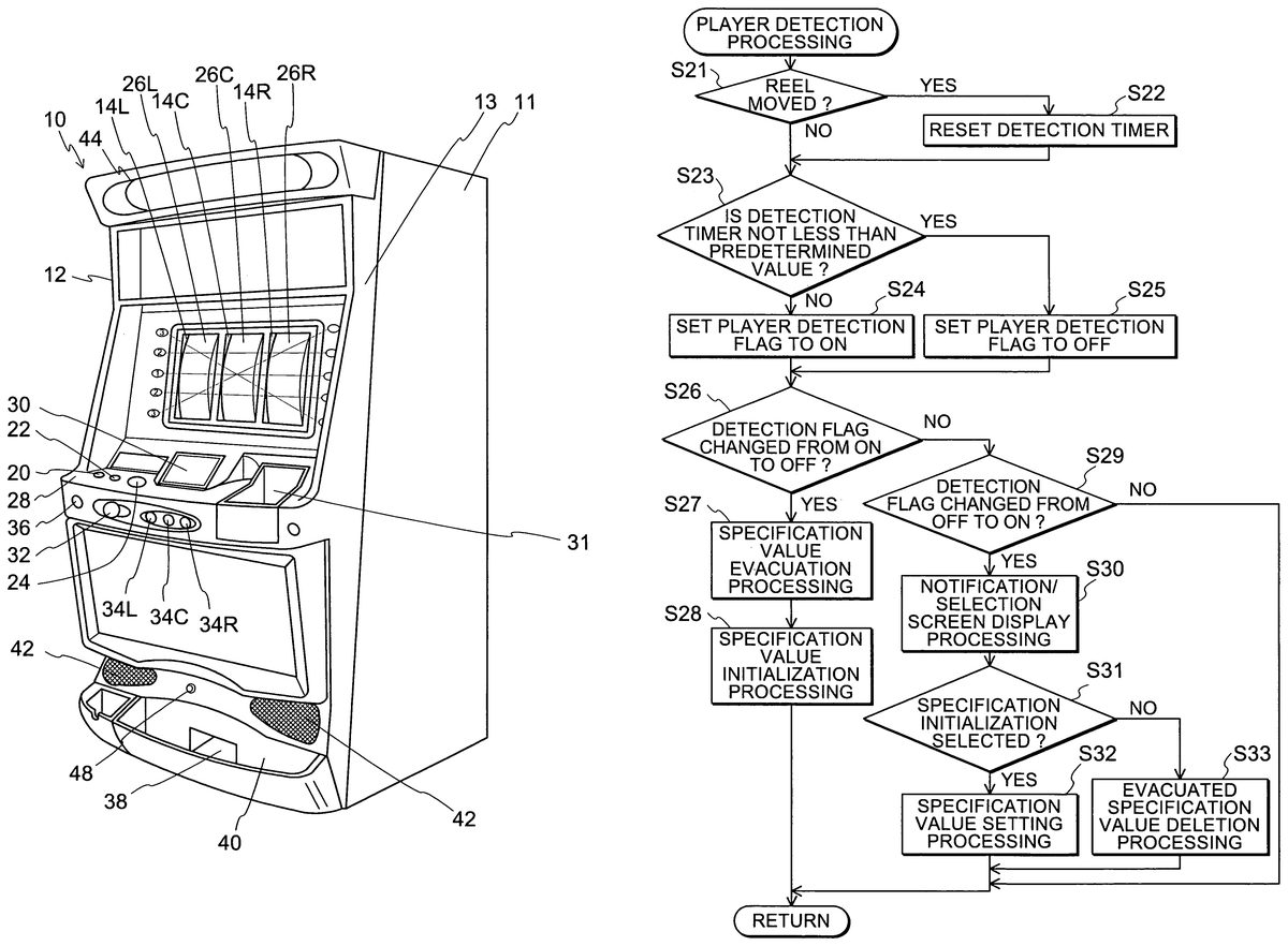
As described above, the processing ofFIG. 16is executed in the sub routine called in step S11.
First, the CPU106determines whether each of the reels26L,26C,26R is varying (step S21). In this processing, the CPU106determines whether the CPU106itself supplies the driving control command to the motor control device117. If the CPU106determines to supply the driving control command to the motor control device117, the CPU106shifts the processing to step S22. If the CPU106determines that no driving control command is supplied to the motor control device117, the CPU106shifts the processing to step S23.
Subsequently, the CPU106executes reset processing of a detection timer (step S22). In this processing, the CPU106resets the detection timer contained in the CPU106. After finishing this processing, the CPU106shifts the processing to step S23.
Subsequently, the CPU determines whether the detection value of the detection timer is not less than a predetermined value (step S23). In this processing, if the CPU106determines that the detection value of the detection timer is not less than the predetermined value, the CPU106shifts the processing to step S25. If the CPU106determines that the detection value of the detection timer is not less than the predetermined value, the CPU106shifts the processing to step S24.
Subsequently, the CPU106executes game player detection flag activating processing (step S24). In this processing, the CPU106records as “ON” the game player detection flag positioned in the RAM110. That is, the CPU106determines that a game player exists. After finishing this processing, CPU106shifts the processing to step S26.
In step S25, game player detection flag inactivating processing is executed. In this processing, the CPU106records as “OFF” the game player detection flag positioned in the RAM110. That is, the CPU106determines that no game player exists. After finishing this processing, the CPU106shifts the processing to step S26.
Subsequently, the CPU106determines whether the detection flag is changed from “ON” to “OFF” (step S26). In this processing, if the CPU106determines that the detection flag positioned in the RAM110is changed from “ON” to “OFF”, the CPU106shifts the processing to step S27. If the CPU106determines that the detection flag is not changed from “ON” to “OFF”, CPU106shifts the processing to step S29.
Subsequently, specification value evacuation processing is executed by the CPU106(step S27). In this processing, various specification values positioned in the RAM110are recorded at positions different from the addresses positioned in the RAM110by the CPU106(that is, the specification values at predetermined addresses (i.e., original addresses) in the RAM110are recorded at addresses different from the original addresses in the RAM110). After finishing this processing, the CPU106shifts the processing to step S28.
Subsequently, the CPU106executes specification value initialization processing (step S28). In this processing, the CPU106initializes various kinds of specification values. Specifically, the CPU106records in a predetermined area of the RAM110each specification value when the total result of the specification value determining table shown inFIG. 7is “−”. After the processing is finished, the CPU106immediately finishes this sub routine.
In step S29, the CPU106determines whether the detection flag is changed from “OFF” to “ON”. In this processing, if the CPU106determined that the detection flag positioned in the RAM110is changed from “OFF” to “ON”, the CPU106shifts the processing to step S30. On the other hand, if the CPU106determines that the detection flag is not changed from “OFF” to “ON”, the CPU106immediately finishes this sub routine.
Subsequently, the CPU106executes notification/selection screen display processing (step S30). In this processing, the CPU106displays an image as shown inFIG. 22. After finishing this processing, the CPU106shifts the processing to step S31.
Subsequently, the CPU106determines whether initialization of specification values is selected or not (step S31). Here, selection of the initialization of the specification values means that the game player touches “YES” of the operation button image displayed on the screen of the display device shown inFIG. 22. Non-selection of the initialization of the specification values means that the game player touches “NO” of the operation button image displayed on the screen of the display device30. In this processing, if the CPU106determines that the initialization is selected, the CPU106shifts the processing to step S32. If the CPU106determines that the initialization is not selected, the CPU106shifts the processing to step S33.
In step S32, the CPU106executes specification value setting processing. In this processing, the CPU106records in the RAM110the various specification values which have been restored in the RAM110through the processing of step S27, whereby the various specification values set previously can be reset. After finishing this processing, the CPU106finishes this sub routine.
In step S33, the CPU106executes restored specification value deletion processing (step S33). In this processing, the CPU106resets the various kinds of specifications restored in the RAM110through the processing of step S27, thereby keeping the initialized state. After finishing this processing, the CPU106finishes this sub routine.
As described above, the processing shown inFIG. 17is carried out in game content control processing called from step S13as described above.
First, the CPU106determines whether a medal is inserted or not (step S41). In this processing, if the CPU106determines that a medal is inserted, the CPU106shifts the processing to step S42. On the other hand, if the CPU106determines that no medal is inserted, the CPU106immediately finishes this sub routine.
In step S42, the CPU106determines whether the BET switch is operated or not. In this processing, if the CPU106determines that the BET switch is operated, the CPU106shifts the processing to step S43. On the other hand, if the CPU106determines that the BET switch is operated, the CPU106immediately finishes this sub routine. The BET switch contains the 1-BET switch20, the 2-BET switch22, and the maximum BET switch24.
In step S43, the CPU106determines whether the start lever32is operated or not. In this processing, if the CPU106determines whether the start lever32is operated, the CPU106shifts the processing to step S44. On the other hand, if the CPU106determines that the start lever32is not operated, the CPU106immediately finishes this sub routine.
In step S44, the CPU106executes gaming machine driving control processing. In this processing, the CPU106executes the control for concrete contents of the game. After finishing this processing, the CPU106shifts the processing to step S45.
Subsequently, the CPU106executes stop winning-combination determination processing (step S45). In this processing, the reel rotation angle position detecting circuit120receives a signal representing a rotation angle position which is output from the rotation angle position sensor. The reel rotation angle position detecting circuit120converts the signal thus received to a predetermined signal. Furthermore, the reel rotation angle position detecting circuit120supplies the received signal to the CPU106through the bus104. The CPU106receiving the signal from the reel rotation angle position detecting circuit120detects the rotation angle position of each of the reels26L,26C,26R on the basis of the signal. Furthermore, the CPU106identifies a winning combination on the basis of the stop positions of the reels26L,26C,26R, that is, symbols (design) stopped and displayed at the display window14, the table representing the stop modes of the symbols for which medals are paid out, and the data indicating activated lines for which medals are betted. Furthermore, the CPU106records the winning-combination data indicating the identified winning-combination in the RAM110. After finishing this processing, the CPU106shifts the processing to step S46.
Subsequently, the CPU106executes payout processing (step S46). In this processing, the CPU106calculates the number of medals to be paid out (hereinafter referred to as “payout number”) on the basis of the kind of the winning-combination determined by the processing in step45. The CPU106supplies a driving signal to the hopper driving circuit126on the basis of the payout number thus calculated. The hopper driving circuit126receiving the driving signal drives the hopper128to pay out medals. After finishing this processing, the CPU106finishes this sub routine.
As described above, the processing shown inFIG. 8is called in the gaming machine driving control processing routine called in step S44.
First, the CPU106executes internal lottery processing (step S51). In this processing, the CPU106outputs a command to the random number generator112to generate a random number. Upon receiving this command, the random number generator112generates a random number. The CPU106records the internal lottery data based on the random number thus achieved at a predetermined position of the RAM110. After finishing this processing, the CPU106shifts the processing to step S52.
Subsequently, the reel rotation control processing is executed (step S52). In this processing, the CPU106outputs a command to the motor control device117to rotate each of the reels26L,26C,26R. Upon receiving the command, the motor control device117transmits to the motor driving circuit118a signal indicating that each of the reels26L,26C,26R is rotated. With this signal, each of the stepping motors62L,62C,62R is driven, and each of the three reels26L,26C,26R starts to rotate. After finishing this processing, the CPU106shifts the processing to step S53.
Subsequently, the CPU106executes reel position detection processing (step S53). In this processing, the CPU106receives signals indicating the rotation angle positions output from the rotation angle position sensors. The reel rotation angle position detecting circuit120converts the signals to predetermined signals. The signals thus converted are supplied to the CPU106through the input-output bus104. The CPU106receiving the signals described above detects the rotation angle positions of the reels26L,26C,26R on the basis of these signals. After finishing this processing, the CPU106shifts the processing to step S54.
Subsequently, the CPU106executes reel stop control processing (step S54). In this processing, the CPU106receives stop signals generated from the reel stop buttons34L,34C,34R through the interface circuit group102and the input-output bus104as described later. The stop signal is generated when the game player pushes each of the reel stop buttons34L,34C,34R. The CPU106receiving each stop signal transmits a stop control signal to the motor control device117through the input-output bus104to stop the reel26L,26C,26R corresponding to the reel stop button34L,34C,34R thus pushed. The motor control device117receiving the signal transmits a driving signal to the stepping motor62L,62C,62R. Each stepping motor62L,62C,62R receiving the corresponding stop signal controls the rotation and stop of the corresponding reel26L,26C,26R and also the controls the rotational speed thereof, whereby symbols drawn on the peripheral surface of each of the reels26L,26C,26R are stopped and displayed. The reels26L,26C,26R are stopped at the positions calculated through the internal lottery processing of step S51. After finishing this processing, the CPU106shifts the processing to step S55.
Subsequently, the CPU106determines whether all the reels are stopped or not (step S55). In this processing, if the CPU106determines that all the reels are stopped, the CPU106finishes this sub routine. If the CPU106determines that al the reels are not stopped, the CPU106shifts the processing to step S53. Specifically, on the basis of the signal indicating the rotation angle position detected through the processing of step S53, the CPU106determines whether the stepping motor62L,62C,62R is stopped. If the CPU106determines that the stepping motors62L,62C,62R are stopped, the CPU106finishes this sub routine. If the CPU106determines that all the stepping motors62L,62C,62R are not stopped, the CPU106shifts the processing to step S53.
As described above, the processing shown inFIG. 19is carried out in the reel stop control processing routine called in step S54.
First, the CPU106determines whether the left reel stop button34L is operated (step S61). In this processing, if the CPU106determines that the left reel stop button34L is operated, the CPU106shifts the processing to step S62. If the CPU106determines that the left reel stop button34L is not operated, the CPU106shifts the processing to step S63.
Specifically, when the CPU106determines that it receives a signal supplied through the operation of the left reel stop button34L, the CPU106shifts the processing to step S62. If the CPU106determines that it does not receive the signal supplied through the operation of the left reel stop button34L, the CPU106shifts the processing to step S63.
In step S62, the CPU106executes left reel stop processing. In this processing, the CPU106transmits a stop signal to the motor control device117. The CPU106stops the stepping motor62L through the motor driving circuit118to stop the left reel26L. The stepping motor62L is stopped on the basis of internal lottery data generated through the processing of step S51and the signal representing the rotation angle position detected through the processing of the step S53. If this processing is finished, the CPU106shifts the processing to step S63.
In step S63, the CPU106determines whether the center reel stop button34C is operated or not. In this processing, if the CPU106determines that the center reel stop button34C is operated, the CPU106shifts the processing to step S64. If the CPU106determines that the center reel stop button34C is not operated, the CPU106shifts the processing to step S65.
Specifically, if the CPU106determines that it receives a signal supplied through the operation of the center reel stop button34C, the CPU106shifts the processing to step S64. If the CPU106determines that it does not receive the signal supplied through the operation of the center reel stop button34C, the CPU shifts the processing to step S65.
In step S64, the CPU106executes center reel stop processing. In this processing, the CPU106transmits a stop signal to the motor control device117. The CPU106stops the stepping motor62C through the motor driving circuit118to stop the center reel26C. At this time, the stepping motor62C is stopped on the basis of the internal lottery data generated through the processing of step S51and the rotation angle position detected through the step S53. If this processing is finished, the CPU106shifts the processing to step S65.
In step65, the CPU106determines whether the right reel stop button34R is operated or not. In this processing, if the CPU106determines that the right reel stop button34R is operated, the CPU106shifts the processing to step S66. If the CPU106determines that the right reel stop button34R is not operated, the CPU106finishes this sub routine.
Specifically, if the CPU106determines that it receives the signal supplied through the right reel stop button34R, the CPU106shifts the processing to step S66. On the other hand, if the CPU106determines that it does not receive the signal supplied through the operation of the right reel stop button34R, the CPU106finishes this sub routine.
In step S66, the CPU106executes the right reel stop processing. In this processing, the CPU106transmits a stop signal to the motor control device117. The CPU106stops the stepping motor62R through the motor driving circuit118to stop the right reel26R. At this time, the stepping motor62R is stopped on the basis of the internal lottery data generated through the processing of step S51and the signal indicating the rotation angle position detected through the processing of the step S53. If this processing is finished, the CPU106finishes this sub routine.
The processing shown inFIG. 20is carried out in the specification value renewal processing routine called in step S13.
First, the CPU106transmits the data of the number of medals to be paid out (step S71). In this processing, the CPU106transmits the data of the number of medals paid out through the processing of step S46, that is, the game result to the server80through the interface circuit group102. After this processing is finished, the CPU106shifts the processing to step S72.
Subsequently, the CPU106determines whether it receives the data of the total result from the server80(step S72). As described later, the server80totalizes the data of the numbers of payout medals transmitted from two gaming machines to calculate a total result. The data of the total result thus calculated is transmitted to each gaming machine through the communication interface circuit90. The CPU106determines whether the data of the total result is received. If the CPU106determines that the data of the total result is received, the CPU106shifts the processing to step S73. If the CPU106determines that the data of the total result is not received, the CPU106determines again whether the data of the total result is received or not.
Subsequently, the CPU106executes specification value determining processing (step S73). In this processing, the CPU106refers to the specification value determining table recorded in the ROM108on the basis of the data of the total result received through the processing of step S72to determine the big-hit shift probability, the payout, and the payout rate. When this processing is finished, the CPU106shifts the processing to step S74.
Subsequently, the CPU106executes the specification value renewal processing (step S74). In this processing, the CPU106renews the respective data of the big-hit shift probability, the payout and the payout rate stored in the RAM110to the respective data of the big-hit shift probability, the payout, and the payout rate determined through the processing of the step S73, and stores the data thus renewed into the RAM110. Specifically, if the total of the numbers of payout medals is not less than a predetermined fixed number, the big-hit probability, the payout and the payout rate are increased. On the other hand, if the total of the numbers of payout medals is less than the predetermined fixed number, the big-hit probability, the payout, and the payout rate are reduced so as to be depreciated. After finishing this processing, the CPU106finishes this sub routine.
FIG. 21shows the data communication between each of the two gaming machines10A,10B and the server80. In the following description, the hardware of the gaming machine10A is represented by adding the reference numerals with a character “A”, and the hardware of the gaming machine10B is represented by adding the reference numerals with a character B.
First, the gaming machine10A executes gaming machine data transmission processing (step S81). In this processing, when the player operates the ten keys displayed on the display device30shown inFIG. 11, the gaming machine10B with which the game player wants to play the game jointly is selected. That is, the gaming machine having a payout medal number with which the player wants to add his/her payout medal number is selected. A signal indicating that the gaming machine10B is selected is transmitted through the interface circuit group102A and the input-output bus104A to CPU106A. The CPU106A transmits the data of the gaming machine10A of the player concerned and the gaming machine10B selected by the player concerned to the server80. After finishing this processing, the CPU106A shifts the processing to step S82.
The server80executes gaming machine data reception processing (step S91). In this processing, the CPU82receives the data of the gaming machine10A of the player and the gaming machine10B selected by the player. After finishing this processing, the CPU82shifts the processing to step S82.
Subsequently, the server80transmits a gaming machine selection notifying signal (step S92). In this processing, the CPU82transmits to the gaming machine10B through the communication interface circuit90a signal indicating that there is a notification that the player of the gaming machine10A wishes to jointly play with the gaming machine10B. After finishing this processing, the CPU82shifts the processing to step S93.
The gaming machine10B receives the gaming machine selection notifying signal (step S101). In this processing, the CPU106B receives from the server80the signal indicating that there is a notification that the player of the gaming machine10A wishes to jointly play with the gaming machine10B. After finishing this processing, the CPU106B shifts the processing to step S102.
Subsequently, the gaming machine10B plays the game (step S102). In this processing, the processing shown inFIGS. 16 to 19described above is carried out in the gaming machine10B. After finishing this processing, the CPU106B shifts the processing to step S103.
Subsequently, the CPU106B transmits the data of the game result (step S103). In this processing, the CPU106B transmits the data of the game result, that is, the data of the number of medals paid out for a predetermined period to the server80through the interface circuit group102B and the input-output bus104B. After finishing this processing, the CPU106B shifts the processing to step S104.
Like the gaming machine10B, the gaming machine10A plays the game (step S82). In this processing, the processing shown inFIGS. 16 to 19described above is carried out. After finishing this processing, the CPU106A shifts the processing to step S83.
Subsequently, the CPU106A transmits the data of the game result (step S83). In this processing, the CPU106A transmits the data of the game result, that is, the data of the number of medals paid out for a predetermined period to the server80through the interface circuit group102A and the input-output bus104A. After finishing this processing, the CPU106A shifts the processing to step S84.
The server80receives the data of the game results (step S93). In this processing, the CPU82receives from the gaming machines10A and10B the data of the game results, that is, the data of the payout medal numbers of the gaming machines10A and10B, and records the data into the RAM86. After finishing this processing, the CPU82shifts the processing to step S94.
Subsequently, the server80totalizes the game results (step S94). In this processing, the CPU82adds the data of the payout medal numbers of the gaming machines10A and10B which are recorded in the RAM86, and records the total result data into the RAM86. After finishing this processing, the CPU82shifts the processing to step S95.
Subsequently, the server80transmits the total result data (step S95). In this processing, the CPU82transmits the total result data calculated in step S94to the gaming machines10A and10B through the communication interface circuits90A and90B. After finishing this processing, the CPU82immediately finishes this sub routine.
The gaming machine10A receives the total result data (step S84). In this processing, the CPU106A receives from the server80the total result data transmitted through the processing of the step S95, that is, the data of the sum of the numbers of medals paid out to the gaming machines10A and10B. After finishing this processing, the CPU106A shifts the processing to step S85.
Subsequently, the gaming machine10A determines the specification values (step S85). In this processing, on the basis of the total result data received in step S84, the CPU106A refers to the specification value determining table recorded in the ROM108A and determines the specification values to be altered. After finishing this processing, the CPU106A shifts the processing to step S86.
Subsequently, the gaming machine10A renews the specification values (step S86). In this processing, the CPU106A renews the probability data, the payout data and the payout rate data recorded in the RAM110A to the corresponding specification values determined through the processing of the step S85. After finishing this processing, the CPU106A immediately finishes this sub routine.
Like the gaming machine10A, the gaming machine10B also receives the total result data (step S104). In this processing, the CPU106B receives from the server80the total result data transmitted through the processing of the step S95, that is, the data of the sum of the numbers of medals paid out to the gaming machines10A and10B. After finishing this processing, the CPU106B shifts the processing to step S105.
Subsequently, the gaming machine10B determines the specification values (step S105). In this processing, on the basis of the total result data received in step S104, the CPU106B refers to the specification value determining table recorded in the ROM108B and determines the specification values. After finishing this processing, the CPU106B shifts the processing to step S106.
Subsequently, the gaming machine10B renews the specification (step S106). In this processing, the CPU106B renews the big-hit shift probability data, the payout data and the payout rate recorded in the RAM110B to the corresponding specification values determined through the processing of the step S105. After finishing this processing, the CPU106B immediately finishes this sub routine.
By carrying out the above-described processing shown inFIG. 21, the specification value is renewed on the basis of the total of the number of medals paid out to the gaming machines10A and10B. Specifically, if the total number of the payout medals is not less than a predetermined fixed number, the specification values are increased. On the other hand, if the total number of payout medals is less than the predetermined fixed number, the specification values are reduced. Accordingly, even when the number of medals paid out to one of jointly-played gaming machines is large, the specification values would be reduced (or depreciated) if the number of medals paid out to the other gaming machine is small, so that the next game play must be carried out under a more unfavorable condition than the preceding game play. Conversely, even when the number of medals paid out for one of the jointly-played gaming machines is small, the specification values would be increased (or improved) if the number of medals paid out to the other gaming machine is large, so that the next game play could be carried out under a more favorable condition that the preceding game play.
In the above embodiment, the gaming machines are designed so that the operations are carried out for the detailed setting by using the touch sensors56. However, this invention is not limited to this mode, and an operating portion such as a switch or the like may be used in place of the touch sensor.
In the above embodiment, the slot machine with which the player operates the stop buttons so as to stop the reels is described. However, the present invention is not limited to this mode. The present applies to a slot machine for the casino such that the reels may automatically stop after they rotate for a certain period of time. Although the slot machine provided with mechanical reels is described in the above embodiment, it should be understood that the present invention may apply to the video slot machine.
Furthermore, in the above embodiment, a gaming machine which can be selected as a jointly-playing gaming machine (i.e., a partner gaming machine) is limited to only one gaming machine10B. However, this invention is not limited to this mode, and plural gaming machines may be selected as partner gaming machines.
Furthermore, in the above embodiment, it is assumed that the player of a gaming machine that is requested to be jointly played necessarily participates in the joint game play irrespective of player's intention. However, this invention is not limited to this mode, and the gaming machine may be designed so that the joint player can reject the offer for playing the game jointly on the player's decision. For example, the gaming machine may be provided with an operating portion such as a switch so that the player may reject the offer.
Furthermore, in the above embodiment, the player is allowed to freely select a gaming machine with which the player wants to totalize the game results (i.e., a partner gaming machine). However, this invention is not limited to this mode, and it may be modified so that a gaming machine with which the game results are totalized (i.e., a partner gaming machine) has been already determined when the player plays the game. For example, a partner gaming machine(s) is/are predetermined at the manufacturing time thereof, or determined on the manager side of the arcade.
In the above embodiment, slot machines are used as the gaming machines. However, this invention is not limited to the slot machines, but it may be applied to pachinko machines or other types of gaming machines.
Furthermore, in the above embodiment, the server totalizes the game results, and transmits the total result to each gaming machine, however, this invention is not limited to this mode. For example, it may be modified so that the server merely receives the game result of each gaming machine and transmits the game result to the game result to the partner gaming machine(s), and the total of the game results is calculated at each gaming machine.
Furthermore, the specification value determining table shown inFIG. 7is used, and the total of the payout medal numbers are associated with each other. However, this invention is not limited to this mode, and the specification values may be determined by using tables shown inFIGS. 23A and 23B. That is,FIG. 23Ashows a table indicating the total result and the change of the specification values based on the total result, andFIG. 23Bshows a table indicating the set number and the specification values (the big-hit shift probability, the payout, and the payout rate) for each set number. As the set number decreases, the specification values are more advantageous to the player. For example, it is assumed that the set number for the specification values is originally set to “8”, and also a total result of “A5to A6” is achieved when a game play is played jointly. At this time, the change is equal to “+2” as shown inFIG. 23A, and thus the set number of the specification values is enhanced to “6”. The specification values may be determined in the manner as described above.
Furthermore, in the above embodiment, the specification values are determined by totalizing the number of medals paid out for a predetermined time period. However, this invention is not limited to this mode. For example, there may be used a mode for predetermining a score for each combination of symbols, and determining the specification values on the basis of comparison of the scores for combinations of symbols achieved after one game is played. Alternatively, there may be used a mode of determining the specification values on the basis of the total of results of a sub game different from the slot game or on the basis of comparison of game results achieved by other methods.
According to this invention, a game result of one player and a game result of other player may be totalized, and the specification values may be changed on the basis of the total result. Therefore, even when the game result of the one player is bad, the specification values may be increased or improved because the game result of the other player could be good. Accordingly, the player may have a sense of anticipation to the game although the his game result is bad. Furthermore, even when the game result of the player is good, the specification values may be reduced or depreciated because the game result of the other player could be bad. In order to avoid such situation, the players do their best to achieve a good game result. Accordingly, exciting and thrilling games can be provided.
Claims
- A first gaming machine for transmitting/receiving data to/from a server, comprising: a specification value setting device for setting at least one specification value as a control condition for game control;a transmitting device for transmitting data of a game result to the server;a gaming machine determining device for determining a second gaming machine operated by a co-player;a total result data receiving device for receiving from the server data of a total game result achieved by the first gaming machine and the second gaming machine based on the data of the game result transmitted by the transmitting device;a specification value determining device for determining a specification value based on the data of the total game result received by the total result data receiving device;and a specification value renewing device for renewing to replace the specification value set by the specification value setting device with the specification value determined by the specification value determining device.
- The first gaming machine according to claim 1 , wherein the gaming machine determining device determines a plurality of gaming machines including the second gaming machine.
- The first gaming machine according to claim 2 , wherein the total result data receiving device receives from the server data of a total game result and wherein the total game result is achieved by the plurality of gaming machines including the first and the second gaming machines.
- A first gaming machine for transmitting/receiving data to/from a second gaming machine operated by a co-player, comprising: a specification value setting device for setting at least one specification value as a control condition for game control;a gaming machine determining device for determining the second gaming machine;a receiving device for receiving from the second gaming machine data of a game result achieved by the second gaming machine;a game result totalizing device for totalizing a game result achieved by the first gaming machine and the game result achieved by the second gaming machine based on the data of the game result of the second gaming machine received by the receiving device so as to calculate a total result;a specification value determining device for determining a specification value based on the total result calculated by the game result totalizing device;and a specification value renewing device for renewing to replace the specification value set by the specification value setting device with the specification value determined by the specification value determining device.
- The first gaming machine according to claim 4 , wherein the gaming machine determining device determines a plurality of gaming machines operated by co-players including the second gaming machine and wherein the first gaming machine transmits and receives data to and from the plurality of gaming machines.
- The first gaming machine according to claim 5 , wherein the receiving device receives data of game results achieved by the plurality of gaming machines including the second gaming machine and wherein the game result totalizing device totalizes a game result achieved by the first gaming machine and the game results achieved by the plurality of gaming machines including the second gaming machines based on the data of the game results of the plurality of gaming machines received by the receiving device so as to calculate the total result.
- The first gaming machine according to claim 1 , further comprising a gaming machine selecting device for selecting the second gaming machine based on an operation by a game player, wherein the gaming machine determining device determines the second gaming machine based on a selection result by the gaming machine selecting device.
- A server for transmitting/receiving data to/from a first gaming machine operated by a game player and a second gaming machine operated by a co-player, comprising: a specification value setting device for setting at least one specification value as a control condition for game control with the first gaming machine;a game result data receiving device for receiving data of a game result transmitted from the first gaming machine and data of a game result transmitted from the second gaming machine;a game result totalizing device for totalizing the game result of the first gaming machine and the game result of the second gaming machine on the basis of the data of the game result transmitted from the first gaming machine and the data of the game result transmitted from the second gaming machine so as to calculate a total result wherein the data of the game results are received by the game result data receiving device;a specification value determining device for determining a specification value based on the total result calculated by the game result totalizing device;and a determined specification value transmitting device for transmitting the specification value determined by the specification value determining device to the first gaming machine and the second gaming machine.
- The server according to claim 8 , wherein the server transmits and receives data to and from a plurality of gaming machines including the first and the second gaming machines.
- The server according to claim 9 , wherein the game result data receiving device receives data of game results transmitted from the plurality of gaming machines including the first and the second gaming machines.
- A program stored on media for directing a computer of a first gaming machine for transmitting/receiving data to/from a server to perform: setting at least one specification value as a control condition for game control with the first gaming machine;transmitting data of a game result to the server;determining a second gaming machine operated by a co-player;receiving from the server data of a total result totalizing the game result achieved by the first gaming machine and a game result achieved by the second gaming machine;determining a specification value based on the data of the total result;and renewing to replace the set specification value with the determined specification value.
- The program according to claim 11 , wherein the computer of the first gaming machine performs determining at least one gaming machine operated by another co-player other than the second gaming machine.
- The program according to claim 12 , wherein the computer of the first gaming machine performs receiving from the server data of the total result totalizing a game result achieved by the at least one gaming machine other than the second gaming as well as the game results achieved by the first and the second gaming machines.
- The first gaming machine according to claim 1 , wherein the specification value comprises a big-hit shift probability, a payout, a payout rate, or a combination thereof.
- A method of renewing at least one specification value for a first gaming machine for transmitting/receiving data to/from a server, comprising: setting a first specification value as a control condition for game control with the first gaming machine;determining a second gaming machine operated by a co-player;performing a game;transmitting data of a game result to the server;receiving from the server data of a total result totalizing the game result achieved by the first gaming machine and a game result achieved by the second gaming machine;determining a second specification value based on the data of the total result;and renewing the specification value from the first specification value to the second specification value.
- A method for setting a value associated with an award obtainable based on a game result from subsequent play of a game on a first gaming machine, comprising: determining a total game result based on a first game result from prior play of a game on the first gaming machine and a second game result from prior play of a game on a second gaming machine;and setting the value in accordance with the determined total game result.
- The method according to 16 , wherein: the value associated with the obtainable award is one of (i) a probability associated with an obtainable big prize payout, (ii) an amount associated with an obtainable regular payout based on a game result from subsequent play of a game on the first gaming machine and a game result from subsequent play of a game on the second gaming machine, and (iii) a rate associated with the obtainable regular payout.
- The method according to 16 , wherein: the determining of the total game result includes summing the first result and the second result.
- The method according to 16 , wherein: the prior played game on the first gaming machine and the prior played game on the second gaming machine are a same type game;and the value is set for subsequent play of the same type game on the first gaming.
- The method according to 16 , wherein: setting the value includes modifying a prior value associated with the award obtainable based on the game result from the prior play of the game on the first gaming machine.
- The method according to 20 , wherein: the prior value is modified to be (i) less favorable to a player of the first gaming machine, if an amount of the determined total game result is less than a threshold amount, and (ii) more favorable to the player of the first gaming machine, if the amount of the determined total game result is more than the threshold amount.
- The method according to 21 , wherein: the threshold amount is a highest amount of a range of amounts extending from a lowest amount of the range to the highest amount;and the prior value is modified to be less favorable to the player of the first gaming machine, if the amount of the determined total game result is within the range of amounts.
- The method according to 16 , further comprising: selecting the second gaming machine prior to determining the total game result.
- The method according to 23 , wherein: the second gaming machine is selected by the first gaming machine in accordance with a predefined selection criteria.
- The method according to 23 , further comprising: accepting, by a player of the second gaming machine, the selection of the second gaming machine by a player of the first gaming machine, prior to determining the total game result;wherein the determining is performed based on the player of the second gaming machine accepting the selection of the second gaming machine.
- The method according to 16 , wherein the value is a first value, and further comprising: setting a second value associated with an award obtainable based on a game result from subsequent play of a game on the second gaming machine, in accordance with the determined total game result.
- The method according to 16 , further comprising: storing a table including predefined different values associated with the award obtainable based on different game results from play of a game on the first gaming machine, for different total game results;wherein the value is set also in accordance with the stored table.
Disclaimer: Data collected from the USPTO and may be malformed, incomplete, and/or otherwise inaccurate.