U.S. Pat. No. 6,937,240
METHODS AND APPARATUS FOR TRANSFORMING THREE-DIMENSIONAL OBJECTS IN VIDEO GAMES
AssigneeSquare Enix Co., Ltd.
Issue DateJanuary 26, 2001
Illustrative Figure
Abstract
In the present invention, for an unprocessed joint, a joint index and a joint rotation angle are obtained (S25, S27). For the unprocessed vertex corresponding to the obtained joint index, a vertex index and a weight w for the vertex are obtained. On the basis of the weight w and the rotation angle in the current frame, coordinate values of the vertex buffer are changed. A quarternion q1 according to the joint rotation angle in the current frame and a unit quarternion are sphere-linear interpolated with the weight w. From the resultant quarternion q, a conversion matrix R is determined for the joint. An overall conversion matrix M is obtained as M=RJTB, where a matrix T represents a relative coordinates from a parent joint, a matrix J represents a basic rotation angle, and B denotes a conversion matrix of the parent joint.
Description
DESCRIPTION OF THE PREFERRED EMBODIMENTS FIG. 1shows an example of a game apparatus101for home use for executing a computer program of an embodiment according to the invention. The home-use game apparatus101for example comprises; a CPU (central processing unit)103connected to an internal bus119, a ROM (read-only memory)104, a RAM (random access memory)105, a HDD (hard disk drive)107, a sound processing section109, a graphics processing section111, a CD-ROM drive113, a communication interface115, and an interface section117. The graphics processing section111has a frame buffer112. The sound processing section109and the graphics processing section111of the home-use game apparatus101are connected to a TV set121having a display screen120. A removable CD-ROM131is fit to the CD-ROM drive113. On the CD-ROM131are recorded a game program133of the invention and data135. The communication interface115is connected through a communication medium141to a network151. To the interface section117are connected a keypad161having operation buttons and a memory card171. The CPU103executes the program stored on the ROM104and executes a game program133stored on the CD-ROM131to control the home game apparatus101. The RAM105is a work area of the CPU103. The HDD107is a memory region for storing for example the game program133and data135recorded on the CD-ROM131. The memory card171is a memory region for storing data the game program133refers to. The sound processing section109, when an instruction to output sound is issued from the program executed with the CPU103, interprets the instruction and outputs sound signals to the TV set121. The graphics processing section111generates graphic data according to the picture producing instruction issued from the CPU103, to write the data into the frame buffer112. The graphic processing section111sends signals for displaying the written graphics data on a display screen120to the TV set121. The CD-ROM drive113reads the game program133and the data135on the CD-ROM131. The communication interface115is connected to the network151through the communication medium141and controls exchange of communication data with other computers. ...
DESCRIPTION OF THE PREFERRED EMBODIMENTS
FIG. 1shows an example of a game apparatus101for home use for executing a computer program of an embodiment according to the invention. The home-use game apparatus101for example comprises; a CPU (central processing unit)103connected to an internal bus119, a ROM (read-only memory)104, a RAM (random access memory)105, a HDD (hard disk drive)107, a sound processing section109, a graphics processing section111, a CD-ROM drive113, a communication interface115, and an interface section117. The graphics processing section111has a frame buffer112.
The sound processing section109and the graphics processing section111of the home-use game apparatus101are connected to a TV set121having a display screen120. A removable CD-ROM131is fit to the CD-ROM drive113. On the CD-ROM131are recorded a game program133of the invention and data135. The communication interface115is connected through a communication medium141to a network151. To the interface section117are connected a keypad161having operation buttons and a memory card171.
The CPU103executes the program stored on the ROM104and executes a game program133stored on the CD-ROM131to control the home game apparatus101. The RAM105is a work area of the CPU103. The HDD107is a memory region for storing for example the game program133and data135recorded on the CD-ROM131. The memory card171is a memory region for storing data the game program133refers to. The sound processing section109, when an instruction to output sound is issued from the program executed with the CPU103, interprets the instruction and outputs sound signals to the TV set121.
The graphics processing section111generates graphic data according to the picture producing instruction issued from the CPU103, to write the data into the frame buffer112. The graphic processing section111sends signals for displaying the written graphics data on a display screen120to the TV set121. The CD-ROM drive113reads the game program133and the data135on the CD-ROM131. The communication interface115is connected to the network151through the communication medium141and controls exchange of communication data with other computers. Operation signals entered through the keypad161are sent through the interface117to the RAM105. The CPU103interprets the input operation signals entered through the keypad161and executes calculating operations.
The game program133and the data135in the embodiment according to the present invention are stored first for example on the CD-ROM131. The game program133and the data135are read with the CD-ROM drive113at the time of execution, and loaded to the RAM105. The data135loaded to the RAM105are, as shown inFIG. 1, a list of vertex coordinates200, a list of normal vectors300, a list of triangular polygons400, a list of vertex groups500, cluster data600, and animation data700. The data storage media used in the course of processing the program related to present invention, include a matrix buffer800, a vertex buffer850, a normal vector buffer870, a matrix cache900, and a frame counter1100, which will be described in detail below. The game program133and data135in the embodiment according to the present invention, which is stored in the CD-ROM131, may be read out from the CD-ROM drive113in advance to be stored in the HDD107. In the case the game program133and data135in the embodiment according to the present invention are stored in the HDD107, the game program133and data135are loaded from the HDD107to the RAM105.
The CPU103processes the game program133and data135of the invention, which have been loaded in the RAM105and issues the resultant signal, a picture producing instruction, to the graphics processing section111. Intermediate data are stored in the RAM105. The graphics processing section111works according to the picture producing instruction from the CPU103, writes the graphics data to the frame buffer112, and sends signals to be displayed on the display screen120to the TV set121.
The program algorithm of the invention executed in the home game apparatus101as described above and the data for use will be described below.
Data for use in connection with the invention will be described in reference toFIGS. 2,3,4,5,6,7,8and9.
FIG. 2shows the vertex coordinates list200of a three-dimensional object constituted with triangular polygons. The vertex coordinates list200includes a column210for vertex coordinate indexes and a column220for coordinates (x, y, z).
InFIG. 2, the coordinates of the vertex index vtx0are (0, 0, 0), the coordinates of the vertex index vtx1are (0, 0, 100), the coordinates of the vertex index vtx2are (0, 100, 0), the coordinates of the vertex index vtx3are (0, 100, 100), and the coordinates of the vertex index vtx4are (100, 0, 0). The coordinates of the vertex in the vertex coordinates list200are relative position coordinates from corresponding joints in a virtual skeleton.
FIG. 3shows a list300of normal vectors. The normal vector list300defines normal vectors at respective vertexes of each triangular polygon, and includes a column310for normal vector indexes and a column320for normal vectors (x, y, z).
InFIG. 3, the normal vector of the normal vector index nml 0 is (1, 0, 0), the normal vector of the normal vector index nml 1 is (−1, 0, 0), the normal vector of the normal vector index nml 2 is (0, 0, −1), the normal vector of the normal vector index nml 3 is (−1, −1, 0), and the normal vector of the normal vector index nml 4 is (0, −1, 0).
FIG. 4shows a triangular polygon list400which stores vertex indexes and normal vector indexes of vertexes 0, 1 and 2 constituting each triangular polygon. The triangular polygon list400includes a column410for triangular polygon indexes, a column420for the vertex indexes and normal vector indexes constituting the vertex 0, a column430for the vertex indexes and normal vector indexes constituting the vertex 1, and a column440for the vertex indexes and normal vector indexes constituting the vertex 2.
InFIG. 4, the vertex 0 of the triangular polygon index plg0 is constituted with the vertex of the index vtx0and the normal vector of the index nml 0, the vertex 1 of the triangular polygon index plg0 is constituted with the vertex of the index vtx1and the normal vector of the index nml 2, and the vertex 2 of the triangular polygon index plg0 is constituted with the vertex of the index vtx2and the normal vector of the index nml 3.
The vertex 0 of the triangular polygon index plg1 is constituted with the vertex of the index vtx0and the normal vector of the index nml 1, the vertex 1 of the triangular polygon index plg1 is constituted with the vertex of the index vtx2and the normal vector of the index nml 3, and the vertex 2 of the triangular polygon index plg1 is constituted with the vertex of the index vtx3and the normal vector of the index nml 4.
Providing the vertex coordinates list200and the normal vector list300, and separately providing the triangular polygon list400for storing the vertex indexes and normal vector indexes makes it possible to also use the same vertex coordinates data and the same normal vector data in the triangular polygon list400. It also facilitates defining a separate normal vector for the same vertex. However, one normal can be made to correspond to only one vertex.
Vertexes that define the three-dimensional object are divided into groups.FIG. 5shows a list500of groups of vertexes. In the vertex group list500are stored: the number of vertex groups, the number of vertexes (members) belonging to each of the vertex groups, each vertex index belonging to the vertex group, the weight predefined to each vertex, the number of normals defined to each vertex, and the normal index of each vertex. Therefore, the vertex group list500includes: the box510for the number of groups, boxes520,522and524for the number of vertexes, boxes530,532,534,536,550,552,554,556and558for the vertex indexes, boxes540,542,544,546,560,562,564,566and568for the weights for vertexes, boxes570,572,574,576,580,582,584,586and588for the number of normals, and boxes591,592,593,594,595,596,597,598and599for the normal vector indexes. When the number of vertexes box appears, data for new vertex groups start. The vertex group numbers are given in order from the head data (data located higher in the Figure) in the vertex group list500.
The number of groups box510inFIG. 5shows that the number of groups is 3. The number of vertexes box520shows that the number of vertexes in the vertex group 0 is 4. In the box530for the vertex indexes belonging to the vertex group 0 is stored the vertex index vtx1. In the box540for the weight to the vertex index vtx1is stored a weight 1.0. In the box570for the number of normals to the vertex index vtx0is stored the value 2. In the box591for the normal vector indexes to the vertex index vtx1are stored normal vector indexes nml 0 and nml 1.
In the box532for the vertex indexes belonging to the vertex group 0 is stored the vertex index vtx2. In the box542for the weight to the vertex index vtx2is stored a weight 1.0. In the box572for the number of normals to the vertex index vtx2is stored a value 1. In the box592for the normal vector indexes to the vertex index vtx2is stored a normal vector index nml 10.
In the box534for the vertex indexes belonging to the vertex group 0 is stored an vertex index vtx3. In the box544for the weight to the vertex index vtx1is stored a weight of 1.0. In the box574for the number of normals to the vertex index vtx3is stored a value 1. In the box593for the normal vector indexes to the vertex index vtx3is stored a normal vector index nml 2.
In the box536for the vertex indexes belonging to the vertex group 0 is stored the vertex index vtx4, in the box546for the weight to the vertex index vtx4is stored a weight of 1.0, in the box576for the number of normals to the vertex index vtx4is stored a value of 2, and in the box594for the normal vector indexes to the vertex index vtx4are stored normal vector indexes nml 3 and nml 1.
The box522for the number of vertexes of the vertex group 1 shows that the number is 4. In the box550for the vertex indexes belonging to the group 1 is stored the vertex index vtx5, in the box560for the weight to the vertex index vtx5is stored a weight 0.5, in the box580for the number of normals to the vertex index vtx5is stored a value of 1, and in the box595for the normal vector indexes to the vertex index vtx5is stored the normal vector index nml 11.
In the box552for the vertex index belonging to the vertex group 1 is stored an vertex index vtx6, in the box562for the weight to the vertex index vtx6is stored a weight of 0.5, a value of 1 is stored in the box582for the number of normals to the vertex index vtx6, and in the box596for the normal vector indexes to the vertex index vtx6are stored normal vector indexes nml 4.
In the box554for the vertex index belong to vertex group 1, a vertex index vtx7is stored. In the box564for the weight to the vertex index vtx7, a weight of 1.0 is stored. In the box584for the number of normals to the vertex index vtx7, the value of 1 is stored. In the box597for the normal vector index to the vertex index vtx7, the normal vector index nml 5 is stored.
In the box556for vertex index belong to vertex group 1, a vertex index vtx8is stored. In the box566for weight to the vertex index vtx8, a weight of 1.0 is stored. In the box586for the number of normals to the vertex index vtx8, the value of 3 is stored. In the box598for the normal vector index to the vertex index vtx8, the normal vector index nml 6, nml 8 and nml 9 are stored.
The box524for the number of vertexes of the vertex group 2 shows that the number is 1. In the box558for the vertex indexes belonging to the vertex group 2 is stored a vertex index vtx7, in the box568for the weight to the vertex index vtx7is stored a weight 0.5, in the box588for the number of normals to the vertex index vtx7is stored a value of 1, and in the box599for the normal vector indexes to the vertex index vtx7is stored normal vector indexes nml 7.
In this embodiment, the weight value is a real number between 0 and 1 and any vertex belongs to one group of vertexes.
FIG. 6shows a front view of an example of a virtual skeleton of a human shaped three-dimensional object10. The virtual skeleton20corresponding to the human shaped three-dimensional object10includes a root joint J2, joints J3, J4, J5, J6, J7, J8, J9, J10, J11, J12, J13, J14and J15, a root bone B2, and bones B3, B4, B5, B6, B7, B8, B9, B10, B11, B12, B13, B14and B15.
The relationships are as follows: The bone B3is imagined to be between the joints J4and J5. The bone B5is imagined to be between the joints J5and J6. The bone B8is imagined to be joined to the joint J6. The root bone B2is imagined to be between the joints J3and J7. The bone B6is imagined to be between the joints J7and J8. The bone B7is imagined to be joined to the joint J8.
The bone B4is imagined to be between the joints J2and J9. The bone B9is imagined to be joined to the joint J9. The bone B11is imagined to be between the joints J11and J14. The bone B14is imagined to be between the joints J14and J15. The bone B15is imagined to be joined to the joint J15The bone B10is imagined to be between the joints J10and J12. The bone B12is imagined to be between the joints J12and J13. The bone B13is imagined to be joined to the joint J13.
The virtual skeleton20is literally virtual and is not displayed on the display screen120. Although the three-dimensional object10is human-shaped, it is provided with joints that do not exist in a real human. The bones are also imaginary.
Although the bones are shown inFIG. 6, they are merely shown to facilitate understanding of the virtual skeleton20. Therefore, the virtual skeleton20has no bone data. That is why the word “imagined” is used in the above description.
The joints are constituted in layers. The joints in the example shown inFIG. 6are constituted in layers as shown in FIG.7. The root joint J2is located at the root of the hip and belongs to the uppermost layer. The child joints of the root joint2are; the joint J3at the root of the right leg, the joint J4at the root of the left leg, the joint J9at the root of the neck, the joint J10at the root of the left arm, and the joint J11at the root of the right arm. Since the joint J3is the one at the root of the right leg of the three-dimensional object10, the child joint of the joint J3is the joint J7, the right knee joint of the three-dimensional object10. The child joint of the joint J7is the joint J8, the right ankle joint of the three-dimensional object10.
The joint J4is at the root of the left leg of the three-dimensional object10. Therefore, the child joint of the joint J4is the joint J5, the left knee joint of the three-dimensional object10. The child joint of the joint J5is the joint J6, the left ankle joint of the three-dimensional object10.
The joint J10is at the root of the left arm of the three-dimensional object10. Therefore, the child joint of the joint J10is the joint J12, the left elbow joint of the three-dimensional object10. The child joint of the joint J12is the joint J13, the left knuckle joint of the three-dimensional object10.
The joint J11is at the root of the right arm of the three-dimensional object10. Therefore, the child joint of the joint J11is the right elbow joint J14of the three-dimensional object10. The child joint of the joint J14is the joint J15, the right knuckle joint.
As shown inFIG. 7, every joint, except for the root joint J2, is always made to correspond to a parent joint. A plurality of child joints may be made to correspond to one parent joint and a joint having no end is not made to correspond with a child joint.
Each vertex corresponding to each joint moves according to the amount of change allotted to each joint. At the same time, the child joint of each joint also moves. For example, when the root joint J2makes a parallel movement, all the joints lower in rank than the root joint J2, namely the entire virtual skeleton20makes a parallel movement. Accordingly, the corresponding three-dimensional object10as a whole makes a parallel movement. Since the movement of the root joint J2affects all the joints, the root joint J2may be used for positional arrangement of the three-dimensional object10.
In this embodiment, the virtual skeleton as described above is used. Joint data600are prepared as shown inFIG. 8for the joints of the virtual skeleton. The joint data600includes for every joint data for the joint and data for the vertex group corresponding to the joint. The joint data also includes data related to the joint layer structure.
In the joint data600, the joint index of the root joint is stored in the root index box610. In the example ofFIG. 8, the joint index is “root.” In the box612of the reference parallel movement amount (x, y, z) of the root joint is stored the position to be the reference of the root joint in the reference attitude of the virtual skeleton. In the example ofFIG. 9, the position is (0, 0, 0). In the box614for the reference rotation angle (Rx, Ry, Rz) of the root joint is stored the rotation angle to be used as the reference of the root joint. In the example ofFIG. 8, it is (0, 0, 90). In the box616for the number of joints is stored the number of joints belonging to the layer below that of the root joint. In the example ofFIG. 8, it is 4.
In the box620for the joint index is stored a joint index joint0 belonging to a layer below that of the root joint. In the box622for the parent index is stored the joint index “root” of the parent joint of the joint “joint0.” In the box624for the reference parallel movement amount are stored relative coordinates (90, 20, 0) to be used as the reference from the parent joint “root” of the joint “joint0” in the reference attitude of the virtual skeleton. In the box626for the reference rotation angle are stored relative rotation angles (0, 0, 135) to be used as the reference from the parent joint of the joint “joint0” in the reference attitude of the virtual skeleton.
In the box628for the number of vertex groups is stored the number of vertex groups corresponding to the joint “joint0.” In the example ofFIG. 8, it is 2. In the boxes630and632for the vertex group numbers are stored vertex group numbers in the vertex group list500corresponding concretely to the joint “joint0.” In the example ofFIG. 8, they are the vertex group 0 and the vertex group 2.
In the box640for the joint index are stored joint indexes of the joints belonging to the virtual skeleton other than the root joint “root” and the joint “joint0.” In the example ofFIG. 8, it is the joint index “joint1.” In the parent index box642for storing the index of the parent joint of the joint “joint1” is stored the joint index “joint0.”
In the box644for the reference parallel movement amount are stored relative coordinates (40, 0, 0) to be used as the reference from the parent joint ‘joint0’ of the joint ‘joint0’ in the reference attitude of the virtual skeleton. In the box646for the reference rotation angle are stored relative rotation angles (0, 0, 45) to be used as the reference from the parent joint “joint1” of the joint “joint1” in the reference attitude of the virtual skeleton.
In the box648for the number of vertex groups is stored the number of vertex groups corresponding to the joint “joint1.” In the example ofFIG. 8, it is 1. In the box650for the vertex group number is stored the vertex group number in the vertex group list500corresponding concretely to the joint “joint1.” In the example ofFIG. 8, it is the vertex group 1.
The operations to the joints of the virtual skeleton for transforming is made according to animation data700shown inFIGS. 9A and 9B. The data include the animation data700A (FIG. 9A) for defining the number of clusters and the number of frames, and animation data700B (FIG. 9B) for defining the rotation angle of each cluster which moves at every frame display period from the start to the end of transformation. In the animation data700B, joints are arranged in order from the root joint to the lowest layer.
InFIG. 9A, the number of joints to be moved is stored in the box710. In the example ofFIG. 9A, the number of joints is 2. The number of time frames from the start to the end of transformation is stored in the box720. In the example ofFIG. 9A, the number of frames is 10. In the following, the rotation angles of the joints of the frame display period are specified in the animation data700B (FIG. 9B) at every two lines corresponding to the number “Z” of the joints to be moved. In the box730for the joint index is stored the index of the joint to be moved. In the box740for the rotation angles (Rx, Ry, Rz) are stored the angles of rotation from the reference attitude.
In the frame 0, the rotation angles of the joint “joint0” to be moved are (0, 0, 0). The rotation angles of the joint “joint1” to be moved are also (0, 0, 0). This means that it remains in the reference attitude. Next, in the frame 1, the rotation angles of the joint “joint0” are (10, 0, 135). The rotation angles of the joint “joint1” are (−10, 5, 45). Data like these follow down to the frame 9. In the frame 9, the rotation angles of the joint “joint0” are (90, 0, 150). The rotation angles of the joint “joint1” are (−90, 45, 45).
In this embodiment, the rotation angle has three parameters, Rx, Ry, Rz. The angle RX denotes the rotation angle about the x axis passing through the joint. The angle Ry denotes the rotation angle about the y axis passing through the joint. The angle Rz denotes the rotation angle about the z axis passing through the joint. While the rotation here is assumed to be made in the order of x, y, and z, it may be made in any order. However, a different order of rotation results in a different position after the rotation. Therefore, it is necessary that the order of rotation at the time of creating data is the same as that at the time of transforming the virtual skeleton.
The data described above are used in this embodiment. Before describing the program processing in this embodiment, the principle of the operation will be described with reference toFIGS. 10A,10B,10c, and10D. The operation of a right arm of a virtual skeleton shown InFIG. 6will be explained hereinafter.
FIG. 10Ashows a two-dimensional virtual skeleton in the state before transformation. The right arm of the virtual skeleton is constituted with joints J11and J14and bones B11and B14.
Beside, in this embodiment, joint0 is assigned to a joint index of joints J11and joint 1 is assigned to a joint index of Joint J14. InFIGS. 10A,10B,10C and10D, a parent joint of Joint J11and a child joint of Joint J14are omitted.
The vertex group 0 and the vertex group2correspond to Joint J11(Joint index joint0) (See FIG.8). The operation example will be explained by paying attention to the vertex group 0. Four vertexes vtx1, vtx2, vtx3and vtx4are included in the vertex group 0 (See FIG.5). The each of the four vertexes vtx1, vtx2, vtx3and vtx4is 1.0 (100%). InFIG. 10A, the positions of four vertexes vtx1, vtx2, vtx3and vtx4are indicated as E1, E2, E3and E4respectively.
While, the vertex group 1 corresponds to Joint J14(Joint index joint1) (See FIG.8). Four vertexes vtx5, vtx6, vtx7and vtx8are included in the vertex group 1 (See FIG.5). The weights of vertexes vtx5and vtx6are 0.5 (50%) and the weights of vtx7and vtx8are 1.0 (100%). InFIG. 10A, the positions of four vertexes vtx5, vtx6. vtx7and vtx8are indicated as E5, E6, E7and E8respectively.
Besides, inFIG. 10A, designations of joints corresponding to the vertexes and weights of the vertexes are shown in the lower portion of the characters denoting the positions E1, E2, E3, E5, E6, E7and E8of the vertexes.
FIG. 10Bshows the virtual skeleton with its joint J14rotated through 60 degrees. However, unlike inFIG. 10A, the vertexes vtx5and vtx6at the positions V5and V6have a weight of 100% rather than 50%. In this case, each of the vertexes corresponding to joint J14moves with the rotation of joint J14. For example, vertex8 moves to the position E8a. As shown inFIG. 10B, it is seen that the position E8aof vertex6 ends up lying inside the three dimensional object. In such a way the three-dimensional object cannot be displayed in a smooth shape.
FIG. 10Cshows a case transformed by a method disclosed in Japanese Patent Laid-open Publication No. Hei-10 74270 referred to in the Related Background Art. In this case, the influence rate of the positions V5and V6of each of vertexes vtx5and vtx6to joint J11is 50% and to joint J14is 100%.FIG. 10Cshows the positions E5and E6of vertexes vtx5and vtx6after transformation where both of the influence rates of the vertexes vtx5and vtx6to Joint11is 100%. Further,FIG. 10Cshows the positions E5aand E6aof the vertexes after transformation in the case that both of the influence rates of the vertexes vxt5 and vxt6 to joint11is 100%. InFIG. 10C, lines connecting between positions of each vertexes prior to and after transformation are shown as a dotted lines in the case that both influence rates of vertexes vtx5and vtx6to joint J14is 100%.
In the technique described in Japanese Patent laid-Open Publication No. Hei-10 74270, the position coordinates of V5and V5aare interpolated with rates of influence on the joints A and B to obtain the position E5bof vertex vtx5. The position coordinates of V6and V6aare also interpolated with rates of influence on the joints J11and J14to obtain the position E6bof vertex vtx6. The vertex positions E5band E6bobtained by interpolation are the positions of vertexes V5and V6after the transformation.
As described in the Related Background Art, if the parent joint, the joint A, of the joint B does not move, the positions E5and E6coordinates themselves may be used in the incorporation process. However, the joint A may actually move. In this case, the positions of vertexes vtx5and vtx6after the movement of joint 11, the positions of vertex vtx5and vtx6after the rotation of joint J14should be calculated by a vertex conversion process. In this case, the vertex conversion must be made twice to obtain the positions of VS and V6, and to obtain the positions of V5aand V6a.
In this embodiment as shown inFIG. 10A, only one weight for one joint J14is defined to correspond to the vertex vtx5in the position E6and the vertex vtx6in the position E6. In the example ofFIG. 10A, both of the weights to the vertexes vtx5and vtx6is 50%. In the case that the weight is 0.5 and the rotation angle of joint J14is 60 degree, in this embodiment, positions of vertexes vtx5and vtx6are calculated when joint14is rotated by 30 degrees. The calculated positions of vertexvtx5and vtx6are matched with positions at which vertexes vtx5and vtx6receive 100% influence (weight 100%) by joint J14rotated by 30 degrees. The calculated positions are made vertexes vtx5and vtx6after transformation.
InFIG. 10D, the bone B14shown with broken lines is the state after being rotated by 30 degrees. The positions of vertexes vtx5and vtx6when the bone B14is rotated by 30 degrees and where vertexes vtx5and vtx6are affected by joint J14by 100% (weight 100%), are E5cand E6crespectively. On one hand, the positions of vertexes vtx7and vtx8of which weights to joint J14are 1.0 (100%), are E7aand E8a. These positions E7aand E8acorrespond to positions when the bone B14is rotated by 60 degrees. As shown inFIG. 10D, in the application of the process according to the present embodiment, the position E6cof vertex6does not dive inside the three-dimensional object and therefore the three-dimensional object after transformation is smooth.
Since the direction of rotation inFIGS. 10A,10B,10C and10D is limited to that about a single axis, the rotation angle corresponding to the weight is obtained easily. Thus, where rotation is made in a three-dimensional space, attention should be paid to the points set forth below.
Counter-clockwise direction of each axis in a positive direction of the axis is assigned to the rotation around each axis as a positive rotational direction in the following explanation. For example, the conversion of rotating in the order of 0 degree about the x-axis, 0 degree about the y-axis, and 90 degrees about the z-axis is completely the same as the conversion of rotating in the order of 180 degree about the x-axis, 180 degree about the y-axis, and −90 degrees about the z-axis. The rotary conversion matrix is also the same.
However, simple changes in the angle of each axis according to the weight due to the vertex of a weight of 50% leads to an undesirable result. That is to say, the former becomes the conversion of rotating in the order of 0 degree about the x-axis, 0 degree about the y-axis, and 45 degrees about the z-axis. The latter becomes the conversion of rotating in the order of 90 degree about the x-axis, 90 degree about the y-axis, and −45 degrees about the z-axis. Although the two produce the same conversion before the change, they become completely different after the change.
Therefore in this embodiment, reflection of the weight is made by the use of a quarternion and sphere-linear interpolation. A brief description of the quarternion and sphere-linear interpolation will be given below.
A quarternion is also known as a four element number and expressed by a combination of vectors and a scalar values. For example, a quarternion q=a+bi+cj+dk, where a, b, c, and d are scalar values, and i, j, and k are unit vectors. An expression such as q=(b, c, d, a)=q(V, a) is also used where Vector V=(b, c, d). A quarternion can express a rotation around a rotary axis after defining the rotary axis.
It is assumed that i represents the x axis, j the y axis, and k the z axis. The quarternion when rotating by Rx turns about the x axis is qx=(sin(Rx/2), 0, 0, cos(Rx/2)). The quarternion when rotating by Ry turns about the y axis is qy=(0, sin(Ry/2), 0, cos(Ry/2)). The quarternion when rotating by Rz turns about the z axis is qz=(0, 0, sin(RZ/2), cos(RZ/2)). The quarternion of rotating in the order of x axis, y axis, and z axis is obtained with grot=gx*qy*qz (The sign * denotes multiplication of quarternions). The sign grot represents a rotary axis and rotation angle for obtaining the same result by a single rotation as the result obtained by rotating in the order of x axis, y axis, and z axis. However, mutual multiplication of quarternions becomes as follows. The sign “X” denotes an outer product and the sign “·” an inner product:
[Equation 1]q1*q2=(V1,w1)*(V2,w2)=(V2*w1+V1*w2+V1×V2,w1*w2-V1·V2)(1)
The sphere-linear interpolation may be easily understood by considering a situation as shown in FIG.11. InFIG. 11, points P1, P2and P3are on an arc whose center is a point O. It is assumed that a vector G is a vector from the point O to a point P1, a vector H is a vector from the point O to a point P2, and a vector P is a vector from the point O to a point P3, and further it is assumed that the angle between the vectors G and H is θ2, the angle between the vectors G and P is θ1, and the vector P is sought. It can be written as P=αG+βH (α and β are real numbers). Since |P|=1, G·H=cos θ2, and G•P=cos θ1, P is obtained from the equation below:
[Equation 2]
P=(Gsin(θ2−θ1)+Hsin θ1)/sin θ2 (2)
If it is assumed that θ1=θ2u (u is [0,1]), it becomes as follows:
[Equation 3]
P=(Gsin(1−u)θ2+Hsin(θ2u))/sin θ2 (3)
The same operation is applicable to the quarternion. When a quarternions q0=(V0, w0) and q1=(V1, w1) are sphere-linear interpolated with t (belonging to [0, 1]), the resultant quarternion becomes as follows:
[Equation 4]
q=(q0*sin((1−t)ω)+q1*sin(t*ω))/sin ω (4)
ω=acos(w0*w1+V0·V1)
The designation (t*ω) denotes a scalar product of t and ω, and the designation a cos denotes arc-cosine.
To obtain the movement destination position E5C and E6C of the vertexes Vtx6 and Vtx6 shown inFIG. 10Din this embodiment, sphere-linear interpolation is applied to the unit quarternion qi=(0, 0, 0, 1) and the quarternion corresponding to the rotation made to the joint J14. It is also possible to simplify as q2=qi, and calculate with q=(1−t)q1+qi*t.
The rotary conversion matrix based on the quarternion q=(x, y, z, w) obtained from the above calculation is as follows.
[Equation 5]
R=1-2*(y*y+z*z)2*(x*y-w*z)2*(x*z+w*y)02*(x*y+w*z)1-2*(x*x+z*z)2*(y*z-w*x)02*(x*z-w*y)2*(y*z+w*x)1-2*(x*x+y*y)00001(5)
The sign * in the equation (5) denotes a scalar product.
For the details of the quarternion and the sphere-linear interpolation, refer toAdvanced Animation and Rendering Techniques Theory and Practice(Alan Watt and Mark Watt, ADDI SON-WESLEY ISBN 0-201-54412-1, p360-p368).
Creating the vertex conversion matrix using the quarternion and the sphere-linear interpolation is like performing the process of (a) obtaining a rotation axis determined from the rotation angle (Rx, Ry, Rz) of the joint and the rotation angle corresponding to the rotation axis, (b) further changing the rotation angle according to the weight predefined to the vertex corresponding to the joint, and (c) rotating about the corresponding rotary axis by the changed rotation angle. Although there are many methods to obtain the same resultant rotation, use of the quarternion and the sphere-linear interpolation is the shortest way to make the intended rotation.
On the basis of the above assumption, the flow of process of this embodiment will be hereinafter described.
At the time of start-up, the CPU103reads the game program133and the data135necessary for the execution of graphics processing and playing games from the CD-ROM131through the CD-ROM drive113on the basis of the operating system stored in the ROM104, and transfers them to the RAM105. The CPU103performs the processes described below by executing the game program133transferred to the RAM105.
By the way, some of the controls and processes performed with the home use game apparatuses101are actually performed with the CPU103in cooperation with circuits other than the CPU103. For the convenience of description, the operation of the CPU103will be mainly explained.
The game program133and the data135necessary for the execution of graphics processing and playing games from the CD-ROM131are actually read according to the instructions from the CPU103and as the process progresses are transferred to the RAM105in succession. However, in the description below, the description of reading the data from the CD-ROM131and transferring to the RAM105is omitted to facilitate understanding the invention.
If the game program133and the data135necessary for the execution of graphics processing and playing games are stored in the HDD107, they are read, according to the instruction of the CPU103, from the HDD107and transferred to the RAM105in succession. However, for clarity purposes as mentioned above, the description of reading the data from the HDD107and transferring to the RAM105is omitted.
FIG. 12shows a main flow of this embodiment. At first, an initial setting is made (step S1). In this initial setting, the data as shown inFIGS. 2to5,8, and9are read and loades in the RAM105. A frame counter is reset to zero. Then the status of the virtual space is set (step S3). The virtual space status setting includes for example; giving an instruction to start the animation of a three-dimensional object by the keypad161operation by the operator, and in the case a viewpoint position is changed also by the keypad161operation by the operator, changing the status in the virtual space accordingly.
Then, the object is transformed according to the invention (step S5). This will be elaborated on later. A picture producing process is applied to the changed three-dimensional object (step S7). Light source calculation and see-through conversion are made and pictures are produced in the frame buffer112. The picture producing process of this embodiment is the same as that of the prior art. Then a frame counter1100is given an increment of 1 (step S9). Whether the process is over is determined (step S11). If the end of the process is shown with the value of the frame counter1100, the process is finished. If not, the process goes back to the step S3.
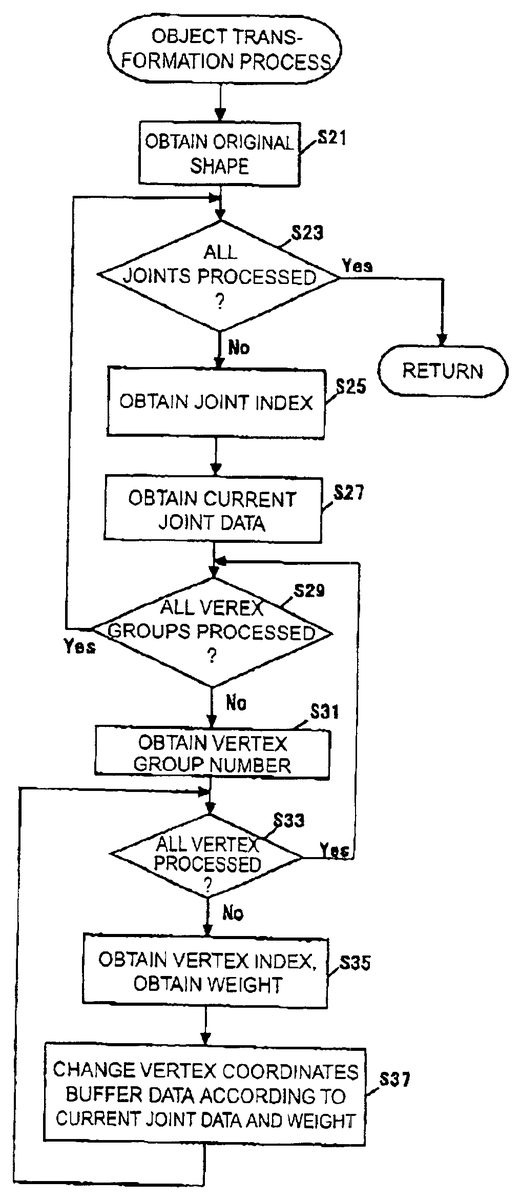
Details of the object transformation process are shown in FIG.13. As seen from the explanation ofFIG. 12, the frame number is known before transforming the object. At first, the original shape of the three-dimensional object is acquired (step S21). Here, the vertex coordinates list200copied to the RAM105is copied to create a vertex buffer850in the RAM105. Whether the transformation process is applied to all the joints is determined (step S23). If the transformation process is applied to all the joints, the process goes to the step S7of FIG.12. If the transformation process is not finished for all the joints, the process goes to the step S25.
In the step S25, a joint index is obtained from the animation data700. Current joint data related to the obtained joint index are obtained (step S27). The current joint data here means the rotation angles (Rx, Ry, Rz) of the joint. As already explained for the animation data700, it is arranged that a rotary angle of the joint is obtained in order from those in higher layers. That is to say, for the joints in higher layers than the joint in the transformation process, the process is performed in a step prior to that of the joint. Therefore, the joints in higher layers are arranged in upper places in the animation data700.
Next, it is determined whether the movement process is completed for all the vertex groups corresponding to the acquired joint index (step S29). If the movement process for all the vertex groups corresponding to the acquired joint index is completed, the process returns to the step S23to move on to the next process for the next joint index. On the other hand, if the movement process is not finished for all the vertex groups corresponding to the acquired joint index, an unprocessed vertex group number is acquired from the joint data600(step S31).
Next, while using the vertex group list500for reference, whether the movement process is finished for all the vertexes belonging to the acquired vertex group number is determined (step S33). The vertex group list500does not include data of the vertex group number. However, the vertex group number can be made known from the number of appearances of the lines520to524of the vertex number (member number) as the vertex group list500is scanned from above. That is to say, the number of appearances of the lines520to524of the vertex number minus 1 is the vertex group number. Therefore, the vertex data related to the obtained vertex group number can be obtained by scanning the vertex group list500from above until the number of appearances of the lines520to524of the vertex number minus1becomes the obtained vertex group number.
If the movement process is finished for all the vertexes belonging to the obtained vertex group number, the process returns to the step S29. If the movement process is not finished for all the vertexes belonging to the obtained vertex group number, vertex indexes yet to be processed are obtained from the vertex group list500and also the weights w (w is not less than 0 and not more than 1) for the vertexes are obtained from the vertex group list500(step S35).
The coordinates data of the vertex buffer are changed on the basis of current joint data (rotation angle in the current frame) and the weight w (step S37). In the step S37, sphere-linear interpolation is applied to the above-described quarternion. That is to say, the quarternion q1 by the rotation angle of the joint in the current frame and the unit quarternion gi are interpolated with the weight w. From the quarternion g obtained by the sphere-linear interpolation, a conversion matrix R in the joint is obtained with the above equation (5).
An overall matrix for obtaining from the original vertex coordinates v the vertex coordinates va after rotation due to the joint rotation becomes M=MJTB using a matrix J representing relative coordinates from a parent joint, a matrix T representing a reference rotation angle, and a conversion matrix B of the parent joint. That is to say, the vertex coordinates va to be finally obtained are obtained from the equation below:
Equation 6
va=vM(6)
The calculated coordinates va=(xa, ya, za) are written to an vertex buffer850. The normal vector of the vertex is taken out of the normal vector list300, converted using the rotary component only of the conversion matrix M into a vector, and written to a normal vector buffer870. As a result, the coordinates of the vertex and the normal vector value are renewed. The renewed coordinates of the vertex and the normal vector value are respectively stored in the vertex buffer850and the normal vector buffer870, and the picture of the three-dimensional object is produced in the frame buffer112according to the contents in the vertex buffer850and the normal vector buffer870.
After the step S37, the process returns to the step S33, and the steps S35and S37are executed until the movement process is finished for all the vertexes in the vertex group.
The process of step S37using the matrix M is an approximation means for executing the process in real time A more accurate normal vector can be obtained by creating the normal vector in consideration of information such as edge data (an angle formed with a neighboring polygon).
In the process of the above step S37, the conversion matrix M is calculated for every vertex. However, it is not necessary to calculated the conversion matrix M for every vertex. In the case of an vertex corresponding to the same joint, a conversion matrix M previously calculated as it is may be used if the same weight is predefined to the vertex. The cache of the conversion matrix M and the buffer of the conversion matrix B will be described below.
FIG. 14shows the matrix buffer800of the conversion matrix B of the parent joint. In each time frame in the animation data700, processing is made in order from the root joint to the joint in the lowermost layer. Since every joint except for the root joint is affected with a parent joint, the conversion matrix B of a weight of 100% of the parent joint is necessary. Also at the time of processing a vertex corresponding to a parent joint, the conversion matrix B as it is can be used if the weight of the vertex corresponding to the parent joint is 100%.
Therefore, in the matrix buffer800, data of the conversion matrix at the weight of 100% are stored for each joint. In the box810, for the joint indexes, are stored joint indexes below the root joint. In the box820, for the matrix data, data of conversion matrixes of respective joints are stored. In the above, it is M=RJTB. Basically, the same equation may be used for calculation. Here are assumed a conversion matrix Ra obtained without using a quarternion with a weight f 100% and a conversion matrix Ba of a weight of 100% of a parent joint of a further parent joint. The conversion matrix B to be obtained is B=RaJTBa.
Two types of embodiments of the cache of the conversion matrix M will be shown here.FIG. 15shows a matrix cache900provided with a box910for storing vertex weight value calculated immediately before and a box920for the conversion matrix M corresponding to the weight. If a plural number of vertexes having the same weight exist for the same joint, a conversion matrix M once calculated may be used again.
Therefore, if a new vertex is processed for movement (FIG.13: step S37), first the matrix cache900is used for reference. A determination is made whether the weight value of the new vertex is in agreement with the weight value stored in the weight box910of the matrix cache900. If in agreement, the data of the conversion matrix M stored in the box920of the conversion matrix M may be used for the new vertex. Therefore, the vertex is moved with the conversion matrix M read out of the matrix cache900. On the other hand, if the weight value of the new vertex is not in agreement with the weight value stored in the weight box910of the matrix cache900, a new conversion matrix M is calculated in the same manner as described above. The new vertex weight and the calculated conversion matrix M are stored in the matrix cache900.
This technique is effective on condition that the vertex indexes are sorted by the vertex weight data for each joint or for each vertex group. The vertex group list500ofFIG. 5shows the manner of the vertex indexes being sorted by the vertex weight data.
InFIG. 15, only the data of one conversion matrix M can be cached. However, inFIG. 16, a method is shown by which data of a plural number of conversion matrixes M are cached. A matrix cache1000includes for each weight: boxes1010,1020, and1030for the weight values; conversion matrix data boxes1012,1022, and1032; and pointers1014,1024, and1034to the next data.
In the example ofFIG. 16, conversion matrixes are stored for weights of 0.4, 0.2 and 0.8. As for the last data, a null is stored in place of a pointer to the next data.
In the case where a new vertex is to be moved (FIG.13: step S37) and the state of the matrix cache1000as shown inFIG. 16is evaluated, first the matrix cache1000is used for reference. A determination is made whether the weight value of the new vertex is in agreement with one of weight values stored in the boxes1010to1030for the weight of the matrix cache1000.
In the case the weight value of the new vertex is in agreement with one of the weight values stored in the boxes1010to1030for the weight of the matrix cache1000, the data of the corresponding conversion matrix M stored in the boxes1012,1022and1032of the conversion matrix M can be used for the new vertex. Therefore, the data is read from the matrix cache1000, and the conversion matrix read is used to move the vertex.
On the other hand, in the case where the weight value of the new vertex is not in agreement with any of weight values stored in the boxes1010,1020and1030for the weight of the matrix cache1000, a new conversion matrix M is calculated in the same manner as described above. And the new data, namely the new vertex weight and the calculated conversion matrix M, are added to the matrix cache1000.
When the matrix cache1000as shown inFIG. 16is used, if the weight for each vertex is defined in hierarchies, the hit rate of the matrix cache1000increases and both the speed and capacity increase. Weights in hierarchies for example are arranged so that they can be set within a range from 0.0 to 1.0, in hierarchies of 0.2. For example it is arranged that weights other than a multiple of 0.2 such as 0.1 and 0.79 cannot be set.
When the matrix cache1000as shown inFIG. 16is used, it works effectively even if the vertex indexes, unlike those in the matrix cache900ofFIG. 15, are not sorted by the vertex weight. However, since a plural number of data exist in the matrix cache1000, a process of searching data from matrix cache1000is necessary.
To increase the search process speed of the matrix cache1000, the following process can be applied.FIG. 17shows schematic representations of a plural number of conversion matrix caches that can be searched at high speeds. In the matrix cache2000shown inFIG. 17, the data for every weight includes; weight boxes2010,2020, and2030, conversion matrix data boxes2012,2022, and2032, next data pointers (next)2014,2024, and2034, and previous data pointers (prev)2016,2026, and2036.
In the example ofFIG. 17, conversion matrix data are stored for the cases of weights of 0.2, 0.4, and 0.8. The conversion matrix with a weight of 0.2 is the head data, and therefore a “null” is stored in the previous data pointer2016. The conversion matrix with a weight of 0.8 is the last data, and therefore a “null” is stored in the next data pointer2034.
The matrix cache2000is always sorted by the weight values. That is to say, in the case a conversion matrix data of a weight is to be added, the weight of each data in the matrix cache200is compared with the weight of the conversion matrix thereof. The comparison is performed in the order of the data having the lower weight in the matrix cache2000. When the data has the weight lower than that of the conversion matrix, the data of the conversion matrix is added before the data.
In the next data pointer2014is stored a pointer indicating the position of the data of a weight of 0.4. In the next data pointer2024is stored a pointer indicating the position of the data of a weight of 0.8. In the previous data pointer2036is stored a pointer indicating the position of the data of a weight of 0.4. In the previous data pointer2026is stored a pointer indicating the position of the data of a weight of 0.2.
For example, when a conversion matrix data of a weight of 0.6 is to be added in the state of data shown inFIG. 17being stored, the data of the weight of 0.6 is added next to the data of a weight of 0.4 and before the data of a weight of 0.8. At that time, a pointer indicating the position of the data of the weight of 0.6 is stored in the pointer2024to the next data of the weight of 0.4. A pointer indicating the position of the data of the weight of 0.6 is stored in the pointer2034to the previous data of the weight of 0.8.
In the example ofFIG. 17, in addition to the matrix cache2000, a reference data pointer2100is provided to indicate the data used for reference immediately before. In the case data is stored in the matrix cache2000and the data in the matrix cache2000is used for reference, pointers directed to the data are stored in the reference data pointer2100.
A data structure ofFIG. 17is prepared and the vertex indexes ofFIG. 5are sorted by the vertex weight data. In the case a new vertex is to be moved (FIG.13: step S37), first the reference data pointer2100is used for reference. And the data in the matrix cache2000indicated with the reference data pointer2100is used for reference. The weight of the vertex to be processed is compared with the weight of the data used for reference.
When the two weights are in agreement as a result of the comparison, the coordinates of the vertex are converted with the conversion matrix of the data used for reference. When the weight of the vertex to be processed is greater than that of the data used for reference, data next to the data used for reference is used for reference. When the weight of the vertex to be processed is smaller than that of the data used for reference, data before the data used for reference is used for reference.
Thereafter, the weight of the data used for reference is compared in succession with the weight of the vertex to be processed. Where the next data is used for reference on the assumption that the weight of the vertex to be processed is greater than the weight of the data used for reference, and as a result of comparison with the next data it is determined that the weight of the vertex to be processed is smaller than the weight of the data used for reference, it is determined that the intended conversion matrix does not exist in the matrix cache2000. In that case, data of the conversion matrix of the newly calculated weight is stored before the data used last for reference.
Where the weight of the vertex to be processed is determined to be greater than the weight of the data used for reference but the pointer to the next data is null, it is determined that an intended conversion matrix does not exist in the matrix cache2000. In that case, data of the conversion matrix of the newly calculated weight is stored next to the data used last for reference.
Likewise, in the case that the next data is used for reference on the assumption that the weight of the vertex to be processed is smaller than the weight of the data used for reference, and the weight of the vertex to be processed is determined to be greater than the weight of the data used for reference as a result of comparison with that of the previous data, it is determined that the intended conversion matrix does not exist in the matrix cache2000. In that case, data of the conversion matrix of the newly calculated weight is stored next to the data used last for reference.
In the case the weight of the vertex to be processed is determined to be smaller than the weight of the data used for reference but the pointer to the previous data is null, it is determined that an intended conversion matrix does not exist in the matrix cache2000. In that case, data of the conversion matrix of the newly calculated weight is stored before the data used last for reference.
Providing the reference data pointer2100as shown in FIG.17and sorting in advance the vertex indexes ofFIG. 5with the vertex weight data, it is possible to detect intended data in an early hierarchy and increase the processing speed.
Sorting and arranging the data in the matrix cache2000according to the weight and providing the data pointers directed to both of the previous and next data make it unnecessary to search for all the data. That is to say, since the data are sorted, the data searching may be made in the increasing or decreasing order of weight depending on the result of comparison of data weights first used for reference. As a result, the search process speed is increased.
As described above, the introduction of the matrix cache reduces the amount of calculation processing of the conversion matrix M and increases the processing speed.
As described above, when the three-dimensional object having a shape determined with a plurality of vertexes is to be transformed, the rotation angle of each joint in a virtual skeleton corresponding to the three dimensional object is obtained at every time frame(step S27). The virtual skeleton is constituted with a plurality of joints, with the plurality of vertexes corresponding to any one of the plurality of joints. The obtained rotation angle of the joint corresponding to each vertex is changed according to the weight predefined for the vertex, and the vertex is moved according to the changed rotation angle at every time frame (step S37).
The rotation angle of the vertex is obtained by changing the rotation angle of the joint corresponding to the vertex according to the weight predefined to the vertex. The vertex is moved according to the rotation angle of the vertex.
Therefore, the three-dimensional object can be smoothly transformed without calculating two pieces of position information for every vertex in a virtual three-dimensional space. Use of quarternions especially enables the rotation of vertexes with a shortest distance between the vertex positions before and after transformation.
Recently the number of vertexes defined for three-dimensional objects has increased greatly because more realistic CG images are desired. According to the present invention, since only one vertex conversion suffices for one vertex in the present invention, a small increase in the processing amount suffices for one vertex.
In other words, even when the three-dimensional object after transformation is not required to be smooth in shape, the transformation requires one conversion for every vertex. Therefore, even if present invention is applied to maintain a smooth shape, the number of vertex conversions remains unchanged.
When the present invention is to be applied, the conversion matrix must be calculated according to the rotation angle of the joint and the weight given to the vertex. However, the conversion matrix calculating process need not be made for every vertex when the matrix caches shown inFIGS. 15to17are used. Therefore, the present invention makes it possible to hold down the increase in the processing amount required for making the post-transformation shape smooth in spite of an increase in the number of vertexes.
In the above embodiment, each vertex is rotated with the same rotary axis as that of the rotation angle of the joint. Therefore, the vertex can be moved while maintaining the distance between the joint to the vertex. For example, since the human knee has bones, the distance between the knee joint to the knee top of the knee portion of a three-dimensional object simulating a human must be kept constant. Applying the invention makes transformation of the joint in the knee portion possible while maintaining the swell of the knee portion.
Displayed Example
FIG. 18shows a polygon model of the leg portion of a human shaped three-dimensional object in a basic attitude. It shows, for reference, a joint J7and bones B2, B6and B7(for the right leg only) of a virtual skeleton (shown in FIG.6). InFIG. 18, portions C and D are shown that are greatly affected when the joint J7is rotated. Changes in three rectangular polygons a1, a2 and a3 of the portion C and five rectangular polygons b1 to b5 of the portion D are observed.
FIG. 19shows a state as a result of rotating the joint J7by the use of present invention. As described above, each vertex of the three-dimensional object is moved by a rotation angle for the vertex obtained by changing the rotation angle of a corresponding joint according to a weight predefined for the vertex. The vertexes of the polygons of the portions C and D shown inFIG. 18correspond to the joint J7. The portion C is moved to the portion Ca, and the portion D to Da.
The polygon a1z of the portion Ca corresponds to the polygon a1 ofFIG. 18, the polygon a2z to the polygon a2 ofFIG. 18, and the polygon a3z to the polygon a3 of FIG.18. The polygon a2z is greatly affected by the rotation of the joint J7and its area has become very small. As seen inFIG. 19, polygons a1z and a3z have become respectively smaller in area than the corresponding polygons a1 and a3.
The polygon b1z of the portion Da corresponds to the polygon b1 ofFIG. 18, the polygon b2z to the polygon b2 ofFIG. 18, the polygon b3z to the polygon b3 ofFIG. 18, b4z to the polygon b4 ofFIG. 18, and the polygon b5z to the polygon b5 of FIG.18. In contrast to the portion Aa, the portion Ba is greatly extended. The polygons b3z and b4z are greatly affected by the rotation of the joint J7and have become greater than the corresponding polygons b3 and b4. The polygons b1z, b2z, and b5z have also become greater than polygons b1, b2, and b5.
From the polygon model ofFIG. 18, an image can be produced as shown inFIG. 20. Athree-dimensional object is expressed in a smooth shape. On the other hand, an image as shown inFIG. 21is obtained from the polygon model shown in FIG.19. When the invention is used to transform a three-dimensional object, as seen inFIG. 21, the vertexes of the polygon in the portion Ca are not buried in the three-dimensional object, and the polygon does not become too large. The three-dimensional object as a whole is drawn in a smooth shape.
The following modifications are applicable to the above embodiments.
(Modification 1)
The animation data700is assumed to include the rotation angle data for all the frames. However, it is not necessary to include the rotation angle data for all the frames. The rotation angle of a frame lacking data may be determined by interpolating the rotation angles of frames located before and after the frame lacking the data.
(Modification 2)
The above description is made on the assumption of a triangular polygon. However, the present invention may be applied to models with polygons comprising more than three vertexes for transforming three-dimensional objects by moving vertexes.
(Modification 3)
The above embodiment shows an example in which conversion matrixes are created. However, processing without using the matrixes is also possible. However, the conversion matrix is advantageous because it can process parallel movements at the same time.
(Modification 4)
In the above embodiment, the weight is reflected by the use of quarternions and sphere-linear interpolation. However, a simple linear interpolation may also be used in place of the sphere-linear interpolation. The term simple linear interpolation means a process of linear interpolation between variables of two quarternions according to their weights. Since the simple linear interpolation is simpler than the sphere-linear interpolation, the use of the simple linear interpolation simplifies the process. Even if the simple linear interpolation is used, three-dimensional objects are not displayed in unnatural shapes on the video game screen as long as the changes in the angle are limited within a certain extent.
(Modification 5)
Changing Hardware for Use:
FIG. 1is an example arrangement which may be modified in various ways. Provision of the communication interface115is optional. Since the present invention is not directly related to the sound processing, provision of the sound processing section109is not essential.
The CD-ROM is merely an example of recording medium, and may be replaced with other recording media such as; internal memory (a ROM for example), DVD-ROM, memory cartridge, floppy disk, magnetic disk, and DVD-RAM. In that case, it is necessary to read the CD-ROM drive113with a corresponding medium to make it a readable drive.
Moreover, the invention is described above as embodied with a computer program. However, the invention may be embodied with a combination of a computer program and a dedicated device such as an electronic circuit, or with only the dedicated device such as the electronic circuit.
While the invention is concretely described above by way of embodiments, the invention is not limited to those embodiments but may be embodied in various ways within the scope and spirit of the invention. For example, while the above description of embodiment of the invention is made with a home game apparatus as a platform, the platform may be realized with an ordinary computer, or an arcade game apparatus. It is also conceivable that a mobile information terminal, car navigation system, etc. are used as the platform.
Moreover, the recording medium for supplying the programs and data for putting the invention to practical use is not limited to the CD-ROM that can be inserted into and removed from the computer or the game apparatus. That is to say, it may be arranged, as shown inFIG. 1, such that the programs and data for putting the invention to practical use are recorded in the memory on the other apparatus side on the network151connected through the interface115and the communication line141, stored in order as required in the RAM105, and used.
According to the invention as described above, the shape of the three-dimensional object after being transformed is smooth since the rotation angle of each vertex is calculated from the rotation angle of each joint and the weight defined to the vertex, and the vertex is rotated through the calculated angle. Moreover, the vertex conversion for each vertex is made only once, so that the increase in the amount of processing can be restricted even if the number of vertexes of the three-dimensional object increases.
From the invention thus described, it will be obvious that the embodiments of the invention may be varied in many ways. Such variations are not to be regarded as a departure from the spirit and scope of the invention, and all such modifications as would be obvious to one skilled in the art are intended for inclusion within the scope of the following claims.
Claims
- A computer-readable recording medium for a video game, with the medium recording a video game program for transforming a three-dimensional object having a shape defined with a plurality of vertexes, the program causing the computer, to obtain the rotation angle of each joint in a virtual skeleton of three-dimensional object constituted with a plurality of joints with each of the plurality of vertexes made to correspond to any one of the plurality of joints according to animation data defining the movement of the virtual skeleton at every frame display period;and to calculate the rotation angle of the vertex on the basis of the obtained rotation angle of each joint and a weight predefined for the vertex corresponding to the joint, and to move the vertex according to the rotation angle at every frame display period, wherein the vertex corresponding to the one joint is sorted with the weight predefined for the vertex;and in the movement of the vertex, a determination is made whether the same weight as that predefined for the vertex moved immediately before is defined for the vertex be moved;when it is determined that the same weight as that predefined for the vertex moved immediately before is not defined for the vertex to be moved, the rotation angle of the vertex to be moved is calculated on the basis of the obtained rotation angle of the joint corresponding to the vertex to be moved and the weight predefined for the vertex to be moved, and data on the rotation angle is stored;the vertex to be moved is moved according to the stored data on the rotation angle, and when it is determined that the same weight as that predefined to the vertex moved immediately before is defined for the vertex to be moved, the vertex to be moved is moved according to the stored data on the rotation angle.
- A computer-readable recording medium for a video game, with the medium recording a video game program for transforming a three-dimensional object having a shape defined with a plurality of vertexes, the program causing the computer;to obtain the rotation angle of each joint in a virtual skeleton of the three-dimensional object constituted with a plurality of joints with each of the plurality of vertexes made to correspond to any one of the plurality of joints according to animation data defining the movement of the virtual skeleton at every frame display period;and to calculate the rotation angle of the vertex on the basis of the obtained rotation angle of each joint and a weight predefined for the vertex corresponding to the joint, and to move the vertex according to the rotation angle at every frame display period, wherein in the movement of the vertex, a determination is made whether the same weight as that predefined for the already moved vertex among the vertexes corresponding to the same joints is defined for the vertex to be moved;when it is determined that the same weight as that predefined for the already moved vertex among the vertexes corresponding to the same joints is not defined for the vertex to be moved, the rotation angle of the vertex is calculated according to the obtained rotation angle of the joint corresponding to the vertex to be moved and the weight predefined for the vertex to be moved, and the data on the rotation angle is associated with the weight of the vertex and stored;the vertex to be moved is moved according to the calculated rotation angle;and when it is determined that the same weight as that predefined for the already moved vertex among the vertexes corresponding to the same joints is defined for the vertex to be moved, the data on the rotation angle stored as associated with the weight predefined for the vertex to be moved is obtained, and the vertex to be moved is moved according to the data on the rotation angle.
Disclaimer: Data collected from the USPTO and may be malformed, incomplete, and/or otherwise inaccurate.