U.S. Pat. No. 11,967,846
MODULAR CHARGER FOR A GAME CONTROLLER
Issue DateSeptember 20, 2021
Illustrative Figure
Abstract
A mobile charger for a game controller includes a printed circuit board supporting a universal serial bus plug at one end of the board and a charging plug at the opposing end, the board further supporting a rechargeable battery, a housing body including a base form having an internal volume and a top plate, the housing body including opposing openings for the USB plug and the charging plug, the top plate including a mounting location for mounting the PCB, the top plate aligned over and mountable to the base form. The USB male plug may be inserted into a female USP port to receive a and whereby the male charging plug may be plugged into a female charge port on the wireless game controller to offload the charge in the rechargeable battery to the wireless game controller rechargeable battery while the controller is use during game play.
Description
DETAILED DESCRIPTION OF THE INVENTION In various embodiments described in enabling detail herein, the inventor provides a unique charging device for a game controller that may be used to charge the controller while it is being used. The present invention is described using the following examples, which may describe more than one relevant embodiment falling within the scope of the invention. It is a goal of the present invention to provide charging capability to a game controller of a computer-aided game during use of the controller to play the game. FIG.1Ais a perspective view of a modular game controller charging device100depicting an end bearing an extended USB plug. Controller charging device100is adapted to provide a charging capability to any game controller of a computer-aided gaming console or gaming box during play of the game without disrupting the game. Charging device100is an assembly of mechanical and electrical components and includes a device housing101that encloses the electrical and mechanical components. Housing101may be molded of a rigid, lightweight, plastic or polymer material. Housing101has a length, a width, and a depth that provides sufficient volume for housing the above-mentioned components. Charging device100includes a printed circuit board (PCB) not visible in this view that supports a PCB rechargeable battery and two opposing charge plugs. In this view, an input universal serial bus (USB) male charge plug104is depicted in an extended position through a rectangular opening in housing101provided for the purpose. In one embodiment, input USB charge plug104is completely retractable into housing101with the aid of a carriage platform that slides longitudinally back and forth within the housing and can be manipulated by a slider mechanism103protruding through slots102provided on opposing sides of housing101, although only one side is shown. Input USB male charge plug104is adapted to plug into a USB charge port on a laptop, a gaming ...
DETAILED DESCRIPTION OF THE INVENTION
In various embodiments described in enabling detail herein, the inventor provides a unique charging device for a game controller that may be used to charge the controller while it is being used. The present invention is described using the following examples, which may describe more than one relevant embodiment falling within the scope of the invention. It is a goal of the present invention to provide charging capability to a game controller of a computer-aided game during use of the controller to play the game.
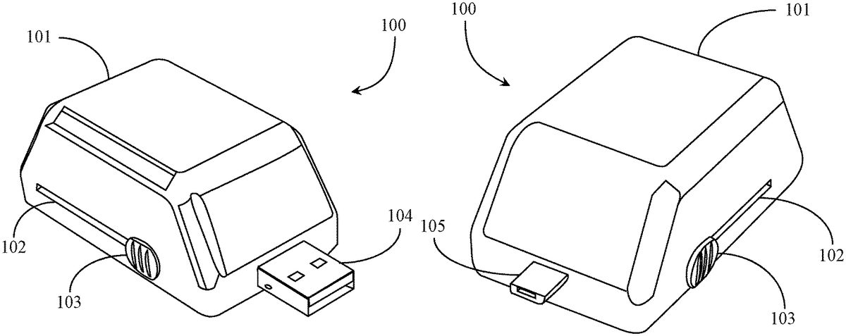
FIG.1Ais a perspective view of a modular game controller charging device100depicting an end bearing an extended USB plug. Controller charging device100is adapted to provide a charging capability to any game controller of a computer-aided gaming console or gaming box during play of the game without disrupting the game. Charging device100is an assembly of mechanical and electrical components and includes a device housing101that encloses the electrical and mechanical components. Housing101may be molded of a rigid, lightweight, plastic or polymer material. Housing101has a length, a width, and a depth that provides sufficient volume for housing the above-mentioned components.
Charging device100includes a printed circuit board (PCB) not visible in this view that supports a PCB rechargeable battery and two opposing charge plugs. In this view, an input universal serial bus (USB) male charge plug104is depicted in an extended position through a rectangular opening in housing101provided for the purpose. In one embodiment, input USB charge plug104is completely retractable into housing101with the aid of a carriage platform that slides longitudinally back and forth within the housing and can be manipulated by a slider mechanism103protruding through slots102provided on opposing sides of housing101, although only one side is shown. Input USB male charge plug104is adapted to plug into a USB charge port on a laptop, a gaming console, or computer to receive power from the onboard power source to charge a battery enclosed within charging device100. Input USB plug104may be plugged into an AC/USB wall adapter that is plugged into a power outlet or into a car jack/USB adapter.
FIG.1Bis a perspective view of modular game controller charging device100ofFIG.1Adepicting an opposing end bearing an extended output micro-USB male plug105. In this perspective view, charging device is rotated 180 degrees to depict the output micro-USB charge plug105extended with the aid of the carriage device describe above. Output micro-USB male plug105adapted to fit into a micro-USB charging port on a game controller to transfer power from the onboard battery to the rechargeable battery in the game controller. The PCB board supporting the opposing USB plugs is shorter in length than hosing101allowing for one of the charge plugs104or105to be retracted into the housing while the other charge plug is extended for use. The carriage platform supports the PCB board and uses slots102as a track system. Slider buttons103are urged in one direction to extend one charge plug or the opposing charge plug for use. Plastic housing101may be radiused or rounded on all edges and corners to promote physical comfort for a user handling the device. Slider buttons103extend through slots102at opposing sides of housing101and may be knurled, slotted, or otherwise surfaced for grip ease afforded to the user operating the device.
FIG.2is a perspective view of a sliding carriage apparatus106of modular game controller device100ofFIG.1AandFIG.1B. Carriage106may be fabricated from a lightweight plastic or polymer material. Carriage106is adapted to support a PCB mounted thereto that includes the opposing plugs104(input USB plug) and105(output micro-USB plug). Slider buttons103extend orthogonal from the longitudinal direction of slide path and are accessible outside of housing101described further above. Slots102support the stems connecting the slider buttons103to the carriage106, such that the carriage is suspended within housing101and may be urged back and forth as required to extend and retract one charge plug or the other charge plug. It is duly noted that the standard size USB charge plug104(FIG.1A) is adapted to receive power from a USB-enabled power source to charge a rechargeable PCB battery (not visible) connected to both opposing charge plugs on the PCB. Output micro-USB charge plug105(FIG.1B) is adapted to charge a rechargeable game controller battery or set of batteries in the game controller through the standard micro-USB charge port on the controller. The charging plugs or ports are not limited to what is shown, but may also include Lightning and Samsung 30-pin. Additional types include USB A-C Type, micro USB A or B, USB mini-b (5 pin or 4 pin) USB 3.0 A or B-Type, USB 3.0 micro B, micro USB AB or USB Mini b (Fugi). The apparatus may be adapted to any plug types known in the art or that may be envisioned in the future.
Sliding carriage106may be fabricated of a lightweight polymer material that may include Delrin or similar dense polymatroids that are machinable and have a low friction coefficient. Carriage106has a machined interface topside113that may serve as a mounting interface for a PCB that includes the opposing USB charge plug components. Opposing slide buttons103extend through slots102(FIG.1A,1B) providing a user interface for extending and retracting each USB charge plug through openings in housing101(FIG.1A,B) provided therein for the purpose.
FIG.3is a perspective view of a housing baseplate107completing housing101ofFIGS.1A and1B. Base plate107may be fabricated of lightweight plastic or polymer material and closes the housing body of housing101to complete the assembly enclosing all of the mechanical and electric components. Mounting posts108are provided at four corners of the rectangular form for the purpose of accepting hardware for closing the modular charging assembly. Baseplate107includes the lower portions109of opposing slots102depicted inFIGS.1A and1B. As well, the openings for the opposing charge plugs are represented herein as lower portions of said openings110for the standard USB plug and111for the micro-USB plug. Modular charger100(FIG.1) may be disassembled by removing baseplate107from the upper housing body. Screws may be used as fasteners to assemble charger100.
FIG.4is a perspective view of a printed circuit board112supporting the opposing USB plugs and a rechargeable battery mounted on the sliding carriage apparatus ofFIG.2. Printed circuit board (PCB)112is adapted to support a PCB rechargeable battery (not pictured here) that may be charged through input USB plug104introduced inFIG.1Aabove and may transfer charge to another rechargeable device through output micro-USB plug105introduced inFIG.1Babove. PCB112includes all of the required circuitry, transistor, resistors, electrical traces, etc. to enable charging the PCB battery and then using the charged battery to power (charge) the battery or batteries of a game controller. PCB112is, in a preferred embodiment, mounted to sliding carriage106introduced inFIG.2above so that each plug might be retracted and extended from housing101introduced inFIGS.1A and1B. In one embodiment, the PCB battery is mounted or otherwise contained on PCB112and is wired to the appropriate leads on the board for charge and for discharge to a game controller. In a preferred embodiment, the PCB battery is a lightweight Li ion or similar rechargeable battery weighing approximately 2-3 grams having a rectangular form of about 0.5 to 1 inch in length, 0.5 inch in width, and a one-eight inch in thickness dimension. In some embodiments, the battery may be cylindrical with dimensions of 18 mm wide and 50 mm long.
FIG.5is an exploded elevation view of game controller charging device100ofFIG.1AandFIG.1Bdepicting order of assembly of parts. In this view, PCB112supporting opposing charge plugs input USB plug104and output micro-USB plug105is mounted to or otherwise affixed to sliding carriage106. In this embodiment a rechargeable PCB battery501(broken boundary) is depicted on PCB112and may be retained thereon by hardware, pocket, or compartment to prevent it from sliding or becoming disconnected from the PCB. The battery501may be larger than shown, having more capacity, the only requirement is that it nests on the PCB and fits within the housing101, not impeding the sliding ability of carriage106. Housing body101fits over carriage106and PCB112and is closed in assembly by base plate107according to the direction of the arrows. A user manipulates carriage106by interaction with opposing slide buttons103. In one embodiment, free movement of carriage106is slightly limited by friction tolerancing wherein the slots are held to a uniform with that is just larger that the width or diameter of the stem portions of slide buttons103allowing frictional contact.
In one embodiment, the carriage platform106is suspended with the housing101of charger device100wherein the bottom surface of the carriage suspends just above the floor of baseplate107. In another embodiment, the friction tolerancing calls for the underside of the carriage to rub against the floor of the baseplate creating some friction so that the retracted and extended positions are maintained positionally without requiring repeated readjustments.
FIG.6is a process flow chart600depicting steps for charging an active game controller while play continues. It is assumed in this process that charging device100is first charged at step601by plugging it into a USB port on a computing device, for example a gaming console, or into a USB port on an AC/USB adapter. At step602, it may be determined by a user whether the game controller charger is fully charged. The modular game controller charger may include one or more light emitting diodes (LEDs) that are visible from outside of the housing for communicating the charge state of the device.
If at step602, the user determines that the game controller charger is not fully charged, the process may loop back to step601. If it is determined that the game controller charger is fully charged at step602, the user and one or more gaming partners may start play at step603. At step604, a player may determine if a game controller requires charging during game play. If at step604it is determined that the game controller does not require charging, then play is continued at step606. If at step604it is determined that a game controller requires charging, then the fully charged game controller charger may be plugged into the micro-USB charge port on the game controller while the game controller is in active use and the process proceeds to step606without interruption of the game in process. After step606, the process loops back to decision step604as game play continues.
In one embodiment of the present invention, the game controller charger may include a retaining spreader clip that may be glued to or otherwise installed over the micro-USB port on the game controller wherein the clip wings may latch into grooves or indents provided on the outside of the housing of the device so that the charger may be retained in port with more structural integrity preventing inadvertent disconnection and mitigating any side-to-side forces against the charger device while it is plugged into the controller. Such an accessory device is not required to practice the present invention but may provide structural integrity to the interface and assurance that inadvertent disconnects do not occur during game play using the controller being charged. More detail about such an accessory clip is provided in the embodiment described below.
FIG.7is an overhead view of a wireless game controller700with the modular charging device ofFIGS.1A and1Bretained in a ported position in the micro-USB charge port of the game controller. In this embodiment, a game controller700is depicted at least in outline. Gaming controls are not illustrated in this view but may be assumed present. Game controller700includes a micro-USB charge port701for accepting a charge plug. Charging device100is plugged into game controller700via micro-USB charge plug105.
In this embodiment, an accessory retainer clip702may be provided with charging device100that may be glued on to or otherwise installed over micro-USB charge port701. Retainer clip702is a spreader clip having two retainer arms with hook ends that may fit within slots or clip depressions placed on the outside opposing sides of game controller charging device100. Retainer clip702may be fabricated of a resilient, somewhat flexible, metal, plastic or polymer composite material. Retainer clip702is adapted to be spread apart, creating tension, at the retainer arms when a user plugs charger device100into charge port701with micro-USB charge plug in extended position. The clip arms of retainer clip702are, in a preferred embodiment, flexed outward by the edge-rounded housing body of the charging device when the device is being plugged in and then snap back to position according to the direction of the arrows with the aid of strategically placed slots or depressions provided on the housing body. Such slots or depressions are adapted to accept the hooked ends of the parallel clip arms in order to secure charging device100into the charge position and provide protection against unintended removal of the charging device due to any forces that might affect the coupling during routine play using game controller700. In a preferred embodiment, the clip arms are sufficiently flexible for enabling a user to remove charging device100from port701by urging one or both of the flexible clip arms back out of the slots or depressions manually, after which the charging device may be unplugged.
FIG.8Ais a front elevation view of the housing retainer clip702ofFIG.7. Retainer clip702has an oblong opening801placed at center of a base strip that may be aligned dimensionally over a micro-USB port like port701ofFIG.7so access to the port is not obstructed. The base strip is flexible and light weight and may conform to a straight surface or to a slightly or moderately curved surface. In the case where a micro-USB port is located on a curved surface, the angle of the clip arms802relative to the base strip may be changed to offset the curvature enabling the same spread and snap in function afforded by the clip hooked ends803. In one embodiment, more than one clip maybe provided with a modular game controller charger like charger100wherein clips are designed specifically for popular game controllers having known contours at the micro-USB charge port surfaces.
FIG.8Bis a side elevation view of housing retainer clip702ofFIG.8A. Retainer clip702has two clip arms802supporting hooked ends803that are adapted to seat into slots or depressions703(FIG.7) provided on the outside opposing surfaces of the game charging device. In one embodiment, small handle forms (not depicted) may be provided on the outside surfaces of the flexible clip arms802so that a user may finger grab them to pull hooked ends803out from the slots or depressions in the housing body of the game charger when decoupling the charge plug from the charge port on the game controller.
In one embodiment, the base strip including around the micro-USB port relief opening may include a glue strip backing804with a peel off cover enabling a user to orient the clip and glue it onto the game controller surface via the backing. In another embodiment, a retainer clip may come with a small diameter drill bit and two small self-tapping screws enabling a user to install the clip and remove the clip if required. Clip702is not specifically required in order to practice the present invention. It may be provided as an accessory to improve the structural integrity of the micro-USB coupling between the charging device of the invention and a game controller when the controller is being charged while in use. In one embodiment, a game controller charging device may be provided as a fixed element with no moving parts such as a slider platform to support PCB112.
FIG.9is a perspective view of a modular game controller charging device900according to another embodiment of the present invention. In this embodiment, charging device900is shown disassembled and having a hollow base form901and a top plate902adapted to be mountable to PCB112and base form901to fix PCB112in position with input USB plug104and output micro-USB plug105extending through appropriately dimensioned material relief openings placed in the end walls of top plate902with material relief extending to the base form901on the side of input USB plug104. Top plate902includes a pair of linearly arranged conical mounting forms903providing screw mounting capability to mount PCB112to top plate902.
Top plate902may be aligned to and installed to base form901using screw hardware, snap hardware, or latch hardware fitted thereto according to the directional arrows. Top plate902has a depth that is sufficient to cover the thickness dimension of PCB112. Base form901is largely hollow having an internal volume (broken boundary) that may be accessed by removing the base form from the top plate and PCB112. Internal volume inside base form901may be used to store a battery connected to PBB112, and perhaps an extra battery. In this embodiment, charging device900has no moving parts like the slider platform introduced inFIG.5as carriage106. Therefore, USB components are not retractable into the charging device housing. In one embodiment, separate end caps made of plastic or rubber may be provided to protect the USB components when charging device900is not in use.
It will be apparent with skill in the art that the modular game controller charging device of the present invention may be provided using some or all the elements described herein without departing from the spirit and scope of the invention. The arrangement of elements and functionality thereof relative to the charging device of the invention is described in different embodiments each of which is an implementation of the present invention. While the uses and methods are described in enabling detail herein, it is to be noted that many alterations could be made in the details of the construction and the arrangement of the elements without departing from the spirit and scope of this invention. The present invention is limited only by the breadth of the claims below.
Claims
- A modular mobile charging apparatus for a wireless game controller comprising: a printed circuit board (PCB) supporting an input universal serial bus (USB) male plug disposed at one end of the board and an output male charging plug disposed at the opposing end of the board, the board having access to a rechargeable battery;a housing body including a base form having an internal volume and a top plate, the housing body including opposing openings for the input USB male plug and the output male charging plug, the top plate including a mounting location for mounting the PCB, the top plate aligned over and mountable to the base form;characterized in that the output male charging plug may be plugged into a female charge port on the wireless game controller to offload the charge in the rechargeable battery to the wireless game controller rechargeable battery while the wireless controller is hand-held, mobile and in a state of use during game play.
- The charging apparatus of claim 1, wherein the input USB male plug is an A-type standard plug and the output male charging plug is a micro USB type A charging plug.
- The charging apparatus of claim 2, wherein the output male charging plug is a USB-C discharge port.
- The charging apparatus of claim 1, wherein the rechargeable battery is mounted to the PCB.
- The charging apparatus of claim 1, wherein the input USB male plug may receive charge from a computing device, a gaming console, a vehicle battery-to-USB adaptor, and an alternating current (AC)-to-USB adaptor.
- The charging apparatus of claim 1, wherein the rechargeable battery has a capacity of equal to or greater than 3.7 volts.
- The charging apparatus of claim 1, wherein the rechargeable battery resides within the internal volume of the base form and is connected to the PCB by wire.
- The charging apparatus of claim 1, further including a retainer clip accessory operated as a separate part installed to the game controller for clipping to the housing body when the output male charging plug is plugged into a micro-USB charge port on the game controller retaining the charging apparatus in inserted position in the port.
- The charging apparatus of claim 8, wherein the retainer clip includes to clip arms spaced apart on a base strip, the base strip including a central opening for providing access to the output micro-USB charge port on the game controller, the clip arms including hooked ends that seat in depressions provided for the purpose on the housing body.
- The charging apparatus of claim 9, wherein the housing body includes slots in place of depressions.
- The charging apparatus of claim 9, wherein the retainer clip is glued onto the game controller via a glue strip provided on the back side of the base strip.
- The charging apparatus of claim 8, wherein the retainer clip is installed onto the game controller using screw hardware.
- The charging apparatus of claim 2, wherein an angle of extension of the clip arms from the base strip is predesigned according to a contour of the game controller surface at the micro-USB charge port.
- The charging apparatus of claim 9, wherein a rounded front of the housing body functions to spread the clip arms of the retainer clip apart before they snap back into their seats during the act of plugging in the output male charging plug into the micro-USB charge port on the game controller.
- A modular mobile charging apparatus for a wireless game controller comprising: a printed circuit board (PCB) supporting an input universal serial bus (USB) male plug disposed at one end of the board and an output charging male plug disposed at an opposing end of the board, the board further supporting a rechargeable battery;a carriage platform to which the PCB is mounted to, the carriage platform including opposing slide buttons extending orthogonally from edges of the carriage platform;and a housing body including a base plate and top housing, the housing body including opposing openings for the input USB male plug and the output charging male plug and opposing slots for supporting the carriage platform at stem portions of the slide buttons, the slide buttons accessible from outside the housing body;characterized in that the input USB male plug and the output male charging plug may be alternatively retracted into and extended out from the housing body by sliding the carriage platform along the slots in the housing body, whereby the input USB male plug may be extended and plugged into a power source to receive a charge to the rechargeable battery and whereby the output male charging plug may be extended and plugged into a mated charge port on the wireless game controller to offload charge to the wireless game controller battery while the controller is in a mobile, hand-held state of use during game play.
- The charging apparatus of claim 15, wherein the carriage platform is frictionally controlled relative to sliding the platform along the slots in the housing body.
- The charging apparatus of claim 1, wherein the frictional control is provided through tight tolerancing of the stem port ins of the slide buttons relative to a slot width in the housing body.
- The charging apparatus of claim 15, wherein the base plate closes the housing body using standard screw hardware.
Disclaimer: Data collected from the USPTO and may be malformed, incomplete, and/or otherwise inaccurate.