U.S. Pat. No. 11,771,997
Method of and System for Preventing Wall Hacking in Video Games by Using Ray Tracing to Filter Outgoing Data Packets
AssigneeTooMuchVoltage Software Inc.
Issue DateJanuary 10, 2022
Illustrative Figure
Abstract
There is provided a method and a system for preventing wall-hacking by using server side ray tracing to filter data packets to be provided to user devices during a multiplayer video gaming session. Map information and player updates indicative of player actions are received, and an acceleration structure is generated. Primary rays from the virtual frustum associated with players are generated and intersections between rays and players geometries on the map are determined based on the acceleration structure. The visibility matrix is generated based on the determined intersections. The visibility matrix includes pair wise visibility information between each player. Data packets provided to each user device are then filtered based on the visibility matrix.
Description
DETAILED DESCRIPTION The examples and conditional language recited herein are principally intended to aid the reader in understanding the principles of the present technology and not to limit its scope to such specifically recited examples and conditions. It will be appreciated that those skilled in the art may devise various arrangements which, although not explicitly described or shown herein, nonetheless embody the principles of the present technology and are included within its spirit and scope. Furthermore, as an aid to understanding, the following description may describe relatively simplified implementations of the present technology. As persons skilled in the art would understand, various implementations of the present technology may be of a greater complexity. In some cases, what are believed to be helpful examples of modifications to the present technology may also be set forth. This is done merely as an aid to understanding, and, again, not to define the scope or set forth the bounds of the present technology. These modifications are not an exhaustive list, and a person skilled in the art may make other modifications while nonetheless remaining within the scope of the present technology. Further, where no examples of modifications have been set forth, it should not be interpreted that no modifications are possible and/or that what is described is the sole manner of implementing that element of the present technology. Moreover, all statements herein reciting principles, aspects, and implementations of the present technology, as well as specific examples thereof, are intended to encompass both structural and functional equivalents thereof, whether they are currently known or developed in the future. Thus, for example, it will be appreciated by those skilled in the art that any block diagrams herein represent conceptual views of illustrative circuitry embodying the principles of the present technology. Similarly, it will be appreciated that ...
DETAILED DESCRIPTION
The examples and conditional language recited herein are principally intended to aid the reader in understanding the principles of the present technology and not to limit its scope to such specifically recited examples and conditions. It will be appreciated that those skilled in the art may devise various arrangements which, although not explicitly described or shown herein, nonetheless embody the principles of the present technology and are included within its spirit and scope.
Furthermore, as an aid to understanding, the following description may describe relatively simplified implementations of the present technology. As persons skilled in the art would understand, various implementations of the present technology may be of a greater complexity.
In some cases, what are believed to be helpful examples of modifications to the present technology may also be set forth. This is done merely as an aid to understanding, and, again, not to define the scope or set forth the bounds of the present technology. These modifications are not an exhaustive list, and a person skilled in the art may make other modifications while nonetheless remaining within the scope of the present technology. Further, where no examples of modifications have been set forth, it should not be interpreted that no modifications are possible and/or that what is described is the sole manner of implementing that element of the present technology.
Moreover, all statements herein reciting principles, aspects, and implementations of the present technology, as well as specific examples thereof, are intended to encompass both structural and functional equivalents thereof, whether they are currently known or developed in the future. Thus, for example, it will be appreciated by those skilled in the art that any block diagrams herein represent conceptual views of illustrative circuitry embodying the principles of the present technology. Similarly, it will be appreciated that any flowcharts, flow diagrams, state transition diagrams, pseudo-code, and the like represent various processes which may be substantially represented in computer-readable media and so executed by a computer or processor, whether or not such computer or processor is explicitly shown.
The functions of the various elements shown in the figures, including any functional block labeled as a “processor” or a “graphics processing unit”, may be provided through the use of dedicated hardware as well as hardware capable of executing software in association with appropriate software. When provided by a processor, the functions may be provided by a single dedicated processor, by a single shared processor, or by a plurality of individual processors, some of which may be shared. In one or more non-limiting embodiments of the present technology, the processor may be a general purpose processor, such as a central processing unit (CPU) or a processor dedicated to a specific purpose, such as a graphics processing unit (GPU). Moreover, explicit use of the term “processor” or “controller” should not be construed to refer exclusively to hardware capable of executing software, and may implicitly include, without limitation, digital signal processor (DSP) hardware, network processor, application specific integrated circuit (ASIC), field programmable gate array (FPGA), read-only memory (ROM) for storing software, random access memory (RAM), and non-volatile storage. Other hardware, conventional and/or custom, may also be included.
Software modules, or simply modules which are implied to be software, may be represented herein as any combination of flowchart elements or other elements indicating performance of process steps and/or textual description. Such modules may be executed by hardware that is expressly or implicitly shown.
With these fundamentals in place, we will now consider some non-limiting examples to illustrate various implementations of aspects of the present technology.
Electronic Device
Referring toFIG.1, there is shown an electronic device100suitable for use with some implementations of the present technology, the electronic device100comprising various hardware components including one or more single or multi-core processors collectively represented by processor110, a graphics processing unit (GPU)111, a solid-state drive120, a random access memory130, a display interface140, and an input/output interface150.
A Graphics Processing Unit or a GPU is an electronic hardware unit designed to provide visuals for computers. It can either be a separate piece of hardware installable on a motherboard, integrated into a motherboard or provided alongside a CPU on the same chip. Modern GPUs are backed by massively parallel processors capable of intensive mathematical computations.
Communication between the various components of the electronic device100may be enabled by one or more internal and/or external buses160(e.g. a PCI bus, universal serial bus, IEEE 1394 “Firewire” bus, SCSI bus, Serial-ATA bus, etc.), to which the various hardware components are electronically coupled.
The input/output interface150may be coupled to a touchscreen190and/or to the one or more internal and/or external buses160. The touchscreen190may be part of the display. In one or more embodiments, the touchscreen190is the display. The touchscreen190may equally be referred to as a screen190. In the embodiments illustrated inFIG.1, the touchscreen190comprises touch hardware194(e.g., pressure-sensitive cells embedded in a layer of a display allowing detection of a physical interaction between a user and the display) and a touch input/output controller192allowing communication with the display interface140and/or the one or more internal and/or external buses160. In one or more embodiments, the input/output interface150may be connected to a keyboard (not shown), a mouse (not shown) or a trackpad (not shown) allowing the user to interact with the electronic device100in addition or in replacement of the touchscreen190.
According to implementations of the present technology, the solid-state drive120stores program instructions suitable for being loaded into the random-access memory130and executed by the processor110and/or the GPU111for preventing wall hacking in video games by using server-side ray tracing. For example, the program instructions may be part of a library or an application.
The electronic device100may be implemented as a server, a desktop computer, a laptop computer, a tablet, a smartphone, a personal digital assistant or any device that may be configured to implement the present technology, as it may be understood by a person skilled in the art.
System
Referring toFIG.2, there is shown a schematic diagram of a system200, the system200being suitable for implementing one or more non-limiting embodiments of the present technology. It is to be expressly understood that the system200as shown is merely an illustrative implementation of the present technology. Thus, the description thereof that follows is intended to be only a description of illustrative examples of the present technology. This description is not intended to define the scope or set forth the bounds of the present technology. In some cases, what are believed to be helpful examples of modifications to the system200may also be set forth below. This is done merely as an aid to understanding, and, again, not to define the scope or set forth the bounds of the present technology. These modifications are not an exhaustive list, and, as a person skilled in the art would understand, other modifications are likely possible. Further, where this has not been done (i.e., where no examples of modifications have been set forth), it should not be interpreted that no modifications are possible and/or that what is described is the sole manner of implementing that element of the present technology. As a person skilled in the art would understand, this is likely not the case. In addition, it is to be understood that the system200may provide in certain instances simple implementations of the present technology, and that where such is the case they have been presented in this manner as an aid to understanding. As persons skilled in the art would understand, various implementations of the present technology may be of a greater complexity.
The system200comprises inter alia a plurality of client devices210, a game server250, and a database240communicatively coupled over a communications network270.
Client Device
The system200comprises the plurality of client devices210or plurality of user devices210. The plurality of client devices210are associated with a plurality of users205, respectively.
As depicted inFIG.2, the plurality of client devices210comprises a first client device212associated with a first user202, a second client device214associated with a second user204, and a third client device216associated with a third user206. It will be appreciated that the number of client devices210is not limited and may include more or less client devices.
As such, each of the client devices212,214,216can sometimes be referred to as a “electronic device”, “user device”, “end user device” or “client electronic device”.
Each of the client devices210comprises one or more components of the electronic device100such as the processor110, the graphics processing unit (GPU)111, the solid-state drive120, the random access memory130, the display interface140, and the input/output interface150.
It will be appreciated that in some embodiments, each client device212,214,216may be implemented differently.
Each of the plurality of client devices210is configured to execute a game client application230(not separately numbered).
Game client application230may be specific to a game or may be used to host multiple different games, with video for a game being presented using a display of the client device212,214,216and interacted with using input/output interfaces of the client device212,214,216. In at least one embodiment, game data may also be stored locally to a database (not shown) or persistent storage device on that client device212,214,216. In at least one embodiment, a processing device of the client device212,214,216is a central processing unit (CPU). In at least one embodiment, the client device212,214,216may also utilize one or more graphics processing units (GPUs) for executing game code.
Game client application230may be obtained over a network, and/or through any of variety of other mechanisms including, but not limited to a portable computer readable storage medium, such as a portable memory device, a DVD, or the like.
The users202,204,206use respective client devices212,214,216to execute game client application230and interact in an environment together during a gaming session by transmitting and receiving data from the game server250and/or to each other.
Each of the users202,204,206can provide input to the respective client devices212,214,216. The input can be or include, for example, a tap or swipe on a touch screen, a point and click with a mouse, and/or one or more entries on a keyboard.
Data corresponding to the input is transmitted from the user interface of the client device212,214,216along a path to the game event procedure executed by the game server250which determines and/or manages game events for the game based on the user input. The game events are generally actions or movements taken by a player or a player's character or avatar in the virtual environment for the online game.
During a given gaming session executed by the game client application230, each user202,204,206is associated with a respective character in the multiplayer game that interacts in a virtual environment. The virtual environment may for example include a map.
As such, the user202,204,206controlling its respective associated character via the respective client device212,214,216may be referred to as respective player212,214,216. Each player212,214,216is associated with identifier.
It will be appreciated that the nature of the character, attributes and possible actions depend on the game provided by the game client application230and the game server250.
As a non-limiting example, the game client application230and the game server250may provide a third person shooter and/or a first person shooter game.
Non-limiting examples of multiplayer video games include the Call of Duty franchise, the Counter Strike franchise, the Quake franchise, Halo franchise and the like.
Game Server
The game server250is configured to inter alia: (i) host an online gaming environment accessible by the plurality of client devices210via the game client application230; (ii) provide online gaming sessions in virtual environments for interaction by the plurality of client devices210by executing a game event procedure; (iii) connect to API235executing a visibility determination procedure310; (iv) receive user inputs in the virtual gaming environment from the plurality of client devices210; (v) process the user inputs in the virtual gaming environment; (vi) update the online game state based on at least the processed user inputs; (vii) perform a visibility determination procedure310using the API235; (viii) filter outgoing data packets using a data filtering procedure300based on the outcome of the visibility determination procedure310; and (ix) provide filtered data packets including updated game states to the client devices210.
It will be appreciated that (ii)-(ix) may be executed a plurality of times, sequentially, in parallel or a combination thereof.
The game server250is an authoritative source of events in the game—it receives and processes player data, while also transmitting game play data to allow connected plurality of client devices210to maintain their own versions of the game world for display in the game client application230.
In some embodiments, the game server250may be hosted or implemented locally, remotely, centrally, distributively, in the cloud, or in any other manner that provides the data communication infrastructure needed for online gaming with the plurality of client devices210. As such, the game server250may also represent a tournament server or an eSport server, which may contain additional modules or components to support competitive gaming broadcast, streaming, and processing.
The game server250is configured to perform filtering of data packets to be provided to the plurality of client devices210by executing the data filtering procedure300so as to prevent wall hacking in the video game. To achieve that purpose, the game server250connects to the API235to perform a visibility determination procedure310, and uses the output of the visibility determination procedure310to perform filtering of packets by executing the data filtering procedure300.
The game server250has components that are sufficient to execute visibility determination procedure310as fast as the time it takes to render one frame of the game state for each client device212,214,216.
As a non-limiting example, a game server250with sufficient capabilities to implement one of NVIDIA OptiX™ Ray Tracing Engine, real-time rendering pipelines that voxelize the scene for the purpose of tracing rays crudely, (signed) distance fields (SDFs), and other geometric primitives may be sufficient to perform the visibility determination procedure310as will be described herein.
As a non-limiting example, a game server250may have as a GPU a RTX2070SUPER from NVIDIA to host a single CS:GO gaming session including 10 players at128tics.
How the game server250is configured to do so will be explained in more detail herein below.
It will be appreciated that the game server250can be implemented as a conventional computer server and may comprise at least some of the features of the electronic device100shown inFIG.1. In a non-limiting example of one or more embodiments of the present technology, the game server250is implemented as a server running an operating system (OS). Needless to say that the game server250may be implemented in any suitable hardware and/or software and/or firmware or a combination thereof. In the disclosed non-limiting embodiment of present technology, the game server250is a single server. In one or more alternative non-limiting embodiments of the present technology, the functionality of the game server250may be distributed and may be implemented via multiple servers (not shown).
In some embodiments of the present technology, at least one of the components may be provided with encryption using any of a variety of encryption mechanisms. In one or more other embodiments, no components may be provided with encryption.
The implementation of the game server250is well known to the person skilled in the art. However, the game server250comprises a communication interface (not shown) configured to communicate with various entities (such as the database240, for example and other devices potentially coupled to the communication network270) via the communication network270. The game server250further comprises at least one computer processor (e.g., the processor110of the electronic device100) operationally connected with the communication interface and structured and configured to execute various processes to be described herein.
Database
A database240is directly coupled to the game server250. In one or more alternative implementations, the database240may be communicatively coupled to the game server250over the communication network270without departing from the teachings of the present technology. In one or more other embodiments, the database240may be optional. Although the database240is illustrated schematically herein as a single entity, it will be appreciated that the database240may be configured in a distributed manner, for example, the database240may have different components, each component being configured for a particular kind of retrieval therefrom or storage therein.
The database240may be a structured collection of data, irrespective of its particular structure or the computer hardware on which data is stored, implemented or otherwise rendered available for use. The database240may reside on the same hardware as a process that stores or makes use of the information stored in the database240or it may reside on separate hardware, such as on the game server250. The database240may receive data from the game server250for storage thereof and may provide stored data to the game server250for use thereof.
In the context of the present technology, the database240is configured to store inter alia game information, player information and/or network information or any other type of information related to the processes described herein. In some embodiments, visibility determination results from data filtering procedure300may be stored for future analysis.
Communication Network
In one or more embodiments of the present technology, the communications network270is the Internet. In one or more alternative non-limiting embodiments, the communication network270may be implemented as any suitable local area network (LAN), wide area network (WAN), a private communication network or a combination thereof. It will be appreciated that implementations for the communication network270are for illustration purposes only. How a communication link275(not separately numbered) between the client device210, the game server250, the database240, and/or another electronic device (not shown) and the communications network270is implemented will depend inter alia on how each electronic device is implemented.
Data Filtering Procedure
The game server250is configured to execute the data filtering procedure300via the API235. The purpose of the data filtering procedure300is to filter outgoing data packets to be transmitted to each of the plurality of client devices210during a multiplayer gaming session so as to prevent wall-hacking.
As such, the data filtering procedure300is configured to inter alia: (i) receive outgoing data packets including updated game states; (ii) execute the visibility determination procedure310to obtain pair-wise visibility information of the plurality of users205; and (iii) filter the outgoing data packets using the pair-wise visibility information to obtain filtered packets for each client device212,214,216; and (iv) transmit the filtered data packets to each client device212,214,216.
The data filtering procedure300further enables saving bandwidth by limiting data that is transmitted from the game to the client devices to only what is required for the users to play the game
The data filtering procedure300starts off by launching an instance of a graphics API. The data filtering procedure300executes a headless instance, i.e., an instance without a graphical user interface (GUI). It will be appreciated that the instance may not be headless if the data filtering procedure300is launched with a debugging view. For example, if an operator of a game server uses a debugging view for debugging the present API235, the instance will not be headless.
The API235launches the visibility determination procedure310in a separate thread which awaits feeding of samplers, material and map geometry instance information. It may be appreciated that procedure300, the API235and visibility determination procedures310may not be threaded but embedded within and executed from the same thread as the game server250.
How the visibility determination procedure310is executed will now be explained with reference toFIG.3.
Visibility Determination Procedure
The visibility determination procedure310is configured to determine pair-wise visibility information of the plurality of users205during one or more frames of a multiplayer gaming session.
In the context of the visibility determination procedure310, the pair-wise visibility information between players is stored in a data structure which will be referred to as visibility matrix hereinafter. The visibility matrix is a square matrix representing the visibility of each player against every other player during the gaming session, as computed using the procedures described hereinafter. The visibility matrix is populated by using ray tracing techniques on the server side such that each client device212,214,216participating in the gaming session receives, from the gaming server250, data packets that have been filtered using the visibility matrix, thus preventing the use of world hacking and wall hacking techniques that enable cheaters to see players that would be otherwise not visible in the environment or map (i.e., as intented by the video game operator or provider) due to objects or other types of opaque obstacles in the map.
Each player is associated with a respective player geometry surrounding its character.
The player geometry may include one of a bounding box and an armature. It will be appreciated that the type of player geometry depends on the type of game. The bounding box is a cuboid surrounding the respective player. The armature is a geometry surrounding the respective player.
In the visibility matrix, all player IDs are labelled on both the rows and the columns. Each cell within the visibility matrix contains a configurable number of Boolean flags that collectively indicate whether the player ID on the column can see the player ID indicated on the row. Each Boolean flag represents the player visibility in a different frame. Any bits within a cell being one represents a transmit decision on the server's part. Only a cell of all zeroes prevents a packet transmit decision.
Reference is now made toFIG.6andFIG.7, which depict respectively a non-limiting example of a scene500involving four players in a video game and the associated visibility matrix520in accordance with one or more non-limiting embodiments of the present technology.
In the non-limiting example illustrated inFIG.7, the visibility matrix520comprises three Boolean flag per cell, thus corresponding to the three different frames during the gaming session. The first frame is depicted inFIG.6, and the second and third frames are set to 0 (not depicted)
The scene500comprises four players located at respective positions: a first player502, a second player506, a third player510and a fourth player514. The scene500depicts a first frame in a first moment in time, which corresponds to the first digit in each cell of the visibility matrix520. The visibility determination of one player against another player is an evaluation of whether any flags within a cell are equal to one. Given that the Boolean flags are stored in individual bits in memory, this temporal visibility determination simply reduces to vector comparisons aided by SIMD units inside the CPU arithmetic and logic units.
The first player502casts rays from the first virtual frustum504. It can be seen that the third player510and the fourth player514are within the casted rays of the first virtual frustum504. The second player506is not within the casted rays of the first virtual frustum504. This is reflected in the first column of the visibility matrix520shown inFIG.7.
The second player506casts rays from the second virtual frustum508. It can be seen that a portion of the third player510and the fourth player514are within the casted rays of the second virtual frustum508. The first player504is not within the casted rays of the second virtual frustum508. This is reflected in the second column of the visibility matrix520shown inFIG.7.
The third player510casts rays from the third virtual frustum512. It can be seen that the first player504and the second player506are within the casted rays of the second virtual frustum508. The fourth player514is not within the casted rays of the third virtual frustum512. This is reflected in the third column of the visibility matrix520shown inFIG.7.
The fourth player514casts rays from the fourth virtual frustum516. It can be seen that a portion of each of the first player502, the second player506and the third player510are within the casted rays of the second virtual frustum508. This is reflected in the fourth column of the visibility matrix520shown inFIG.7.
In some embodiments, each cell holds more than one flag because visibility determination for frames independent of each other may not be taken into account and a limited history of visibility may be taken into account. It will be appreciated that visibility is unidirectional: player1seeing player2does not guarantee that player2is in fact capable of seeing player1. A frame counter is used and monotonically increases by one with every passing frame. The modulus of the frame counter with the number of Booleans that fit in a single cell determines which flag in every cell will be evaluated at any given frame. Beginning with every frame, flags associated with that frame in each cell are reset to zero indicating a lack of visibility.
The visibility determination procedure310casts rays from every player's virtual frustum using the player's aspect ratio. Each player's aspect ratio is received from the game server250, and matches that of the player's. An under-reported ratio places the player at a disadvantage and an over-reported ratio should be rejected server-side and regarded as misinformation. This mechanism prevents players (i.e. client devices) from abusing the data filtering procedure300. In scenarios where this information is not available, a reasonable maximum frustum aspect ratio is used for all players equally (e.g., 16:9).
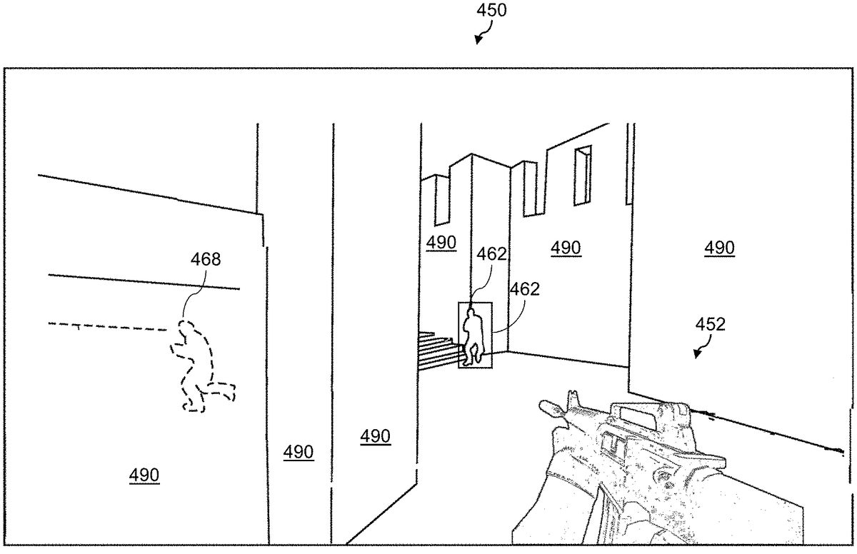
With brief reference toFIG.4, there is illustrated a non-limiting example of a simplified first person view frame in a video game hostable by the game server250and executable by the game client application230of a given one of the client devices212,214,216.
The client device212controls first player452in first person view and may interact with the virtual environment or map (collectively represented by map elements490). The map elements490may include walls, doors, objects, etc.
Other players462,468participate in the online gaming session and also interact together and/or with the virtual environment. The first player452sees second player462, which is located in front of him. Fourth player468(depicted in dotted lines) is located behind a wall and should not be normally visible to the first player452. However, if the first player452uses wall hacking code on the game client application230, the first player452may gain an unfair advantage over remaining players.
In the illustrated example, the procedures and methods described herein are intended to prevent first player452from wall hacking.
In one or more embodiments where only bounding boxes are available, the rays will register player visibility as they intersect player bounding boxes and continue along the ray direction as if these intersections did not occur until encountering a solid wall. This prevents players' bounding boxes from hiding each other in the event that they line up behind each other visually. This scenario, which is referred to as an independent visibility scenario, is depicted inFIG.5A, which illustrates a ray407casted from a player virtual frustum405intersecting with bounding boxes412,416,420of players410,414and418until it encounters a solid wall430.
Independent visibility includes any visibility generated by player geometry resulting from a sequence of rays casted irrespective of any source of light. As a non-limiting example, independent visibility can be a single ray casted directly from a viewer's frustum.
Another scenario arises when a player's body is leaving casted shadows on the surrounding environment due to a source of light. This scenario is referred to as dependent visibility, and is depicted inFIG.5B, where a secondary ray409is casted from an intersection of primary ray408originating from the player virtual frustum405is intersecting with bounding boxes412,416,420of players410,414and418until it encounters a solid wall430. With a sun435as a light source behind the solid wall430. If the same visibility determination procedure310were to be used forFIG.5B, it would falsely inform that 3 player shadows are visible, which is not true due to wall430behind those players obscuring player shadows.
Thus, to overcome this problem in the dependent visibility scenario, the visibility determination procedure310accumulates player IDs along the path into the ray's payload and only registers visibility for those accumulated players if the shadow ray fails to register a hit with the map. A non-limiting example of this packing strategy is illustrated below:
Layout (location = 0) rayPayloadInEXT struct {/*2 bits:rayMask compressed2 bits:hitType1 bit:secondary ray flag3 bits:player hit booleans via secondary ray6 bits:originating player ID6 bits:1stplayer hit via secondary6 bits:2ndplayer hit via secondary6 bits:3rdplayer hit via secondary*/uint rayMaskHitTypeSecFlagSecHitsPlayerIds;} rayLoad;
In this example, the entire payload is represented using 32 bits and can contain dependent visibility for 3 players back to back. An additional 32 bits will be sufficient to accommodate dependent visibility for 4 more players (accounting for additional hit flags). It will be appreciated that such optimization is game-specific and has to be done on a per-game basis and involves knowing the upper bound on the number of players in a session at any given time. The ray mask is utilized to avoid intersecting friendly players as their information is always transmitted. The hit type indicates one of the following:
0) No hit was registered. The primary ray escaped to the sky.
1) Only the environment was hit by the primary ray.
2) Players were registered as independently visible via the primary ray.
3) Player hits were packed onto the ray payload via the shadow ray.
It will be appreciated that this information is useful for debugging and to also register dependent visibility at the end of a traversal if and only if a shadow ray missed the map, thus reaching the light source and leaving shadows of players intersected along the way.
Turning back toFIG.3, the visibility determination procedure310comprises inter alia a preparation procedure320including map data preparation procedure328and a player data preparation procedure324, a pre-pass procedure330, and a ray-casting procedure350.
In one or more embodiments, the ray casting-procedure350comprises one of a super sampling procedure360and an importance sampling procedure370.
Additionally, a force-casting procedure380may be launched.
It will be appreciated that the electronic device executing the visibility determination procedure310does not require a display output.
In one or more embodiments, for example if the game supports player appearances with greatly varying materials, the visibility determination procedure310is configured to cache the range of materials that describe the varieties of player appearances to avoid retransmitting them later. The cached range of materials may be retained until the next map change.
Preparation Procedure
The updated player information is transmitted by each client device212,214,216to the game server250. The updated player information comprises, for each client device212,214,216respectively, actions of the respective player on the map.
In one or more embodiments, the actions include one or more of: player actions related to movement (e.g., strafing, crouching, moving forward or backwards, jumping etc.), player actions resulting in changes in viewing direction (e.g., moving the mouse, gun recoil due to fired weapon etc.), player actions related to gameplay (e.g., firing bullets, opening doors, picking up items, etc.)
In one or more other embodiments, the actions may further include one or more of: entirely new player viewing directions, aspect ratio and vertical or horizontal field of view, entirely new player positions, player health, animation states, updated lighting information indicating dynamic lighting in the map, and changes to a subset of map geometry instances indicating a dynamic map.
The game server250updates the game state to obtain a current or updated game state based at least in part on the updated player information received from the plurality of client devices210.
The game server250then transmits at least a portion (i.e., a subset) of the updated player information to the player data preparation procedure324.
Player Data Preparation Procedure
The player data preparation procedure324is executed and receives, from the game server250, at least a portion of the updated player information or player updates at every frame.
The player data preparation procedure receives, for each player or client device212,214,216, current vantage point data and future vantage point data.
The current vantage point data includes, for each player, eye data, look data, up data, aspect ratio and y-field of view (FOV). It will be appreciated that eye data in this context refers to the current three dimensional location of the player's eye in space, look data refers to the current direction that the player is looking at described by a unit length vector in three dimensional space, up refers to a current direction pointing from the tip of the player's head towards the sky, again provided in unit length in three dimensional space. The up direction is orthogonal to the look direction (forms a 90 degrees celcius angle).
The future vantage point data includes, for each player: future eye, future look, future up, future aspect ratio and future y-FOV.
It will be appreciated that that the current vantage point data and the future vantage point data are determined by the game server250and provided to the player data preparation procedure324.
In one or more embodiments, for example when the client devices212,214,216are located remotely (i.e., not in LAN), the player data preparation procedure324receives lagging indicators for each client device212,214,216. The lagging indicators may include for example a ping associated with each player, or an indication that the ping is above a predetermined threshold known to the player data preparation procedure324.
The updated player information comprises, for client device212,214,216respectively, actions of the respective player on the map.
In one or more embodiments where the video game executed by the game client application230and the game server250support dynamic map changes, the player data preparation procedure324receives indication of changes to the map.
In one or more embodiments where the video game executed by the game client application230and the game server250support dynamic lighting, the player data preparation procedure324receives indications of change to lighting information.
The player data preparation procedure324is configured to generate, for each player, based on the player geometry, the current vantage point data and the future vantage point data, respective collated player geometry.FIG.10shows an example of a collated player geometry670, where a player is shown at a current time t (672), future time t+1 (674) and future time t+2 (676) with virtual frustum678from another player attempting to intersect the collated player geometry670.
In one or more embodiments, the collated player geometry is generated using the current eye and future eye vantage point data.
In one or more other embodiments, the collated player geometry is generated further using a future bounding box. Such a future bounding box causes the dimensions of the bounding box to interpolate as well as its position while future versions of the bounding boxes are being generated and collated.
In one or more other embodiments, when armatures are available instead of bounding boxes, the player data preparation procedure324further uses current and future animation states to generate the collated player geometry.
The player data preparation procedure324thus obtains, for each player, a respective collated player geometry.
The player data preparation procedure324additionally initializes bits within the visibility determination matrix for the current frame to zero.
Map Preparation Procedure
The map data preparation procedure328receives map geometry instances.
In one or more embodiments, the map data preparation procedure328receives the samplers and materials for map geometry instances.
In one or more embodiments, the map data preparation procedure328further receives samplers and materials for players.
In one or more embodiments where the video game executed by the game client application230and the game server250support dynamic lighting, the map data preparation procedure328receives indications of change to lighting information.
The map data preparation procedure328is configured to generate an acceleration structure. The acceleration structure to generate comprises a top level acceleration structure (TLAS) comprised of a plurality of bottom-level acceleration structures (BLASes).
The map data preparation procedure328is configured to generate BLASes using the map geometry instances.
The BLASes are acceleration structures representing chunks of triangles or shapes arranged together on a top-down structure.
The map data preparation procedure328is configured to generate the TLAS by combining the BLASes of map geometry instances together.
The TLAS represents an entire scene. The two-level design of the TLAS allows composing different scenes by mixing and matching different BLASes together.
It will be appreciated that respective player and map geometry instance materials may be used alongside the TLAS.
The map data preparation procedure328outputs the TLAS.
Pre-Pass Procedure
The pre-pass procedure330is configured to generate look-a-head corners using a look-a-head procedure334and bound stretchings using a bound stretching procedure338.
In one or more embodiments, the pre-pass procedure330is configured to generate acceleration structures including BLASes and a TLAS for lagging players only.
Look-a-Head
The look-a-head procedure334is configured to: (i) determine respective origins of each of the plurality of virtual sub-frusta; and (ii) clip the respective origins against the map.
In one or more embodiments, the look-a-head procedure334is configured to construct a ray segment starting from the player's current eye (i.e., origin) and ending at a quarter of the player's height above the eye, clip the ray segment against the map at a clipped position, and from the clipped position, build four additional ray segments aligned laterally with the four upper corners of the player's current bounding box.
The look-a-head procedure334is configured to repeat steps (i)-(ii) with the initial ray segment ending instead at half the player's height below the current eye. This provides another four (4) of the virtual sub-frusta origins.
In one or more embodiments, when armatures are available instead of bounding boxes, the look-a-head procedure334is configured to, from the clipped position, build four additional ray segments aligned laterally with the four upper corners of a bounding box surrounding the player armature.
FIG.11illustrates an approximate arrangement of a plurality of sub-frusta704(not separately numbered) with a main sub-frusta706in accordance with one or more non-limiting embodiments of the present technology.
Bound Stretching Procedure
With insufficient virtual resolutions it is possible for distant players to become invisible as their occupied virtual screen real-estate shrinks. While in some embodiments, the visibility determination procedure310employs a jitter similar to temporal super-sampling to capture sub-pixel detail, additional measures may further be used. The pre-pass procedure determines how far player geometries (e.g., bounding boxes or armatures) can be stretched without exceeding twice their initial volume or intersecting the map world at large. The information gathered is used to increase player sizes as the virtual resolution shrinks, which is referred to as bound stretching.
The bound stretching procedure338is configured to inter alia: (i) receive the current player geometry (i.e., one of bounding box or current player armature); (ii) construct a ray segment from the center of the player geometry in the positive X direction with A times the size of the X dimension of the player geometry, where A is a configurable threshold, (e.g. A=1.13); (iii) clip the ray segment against the map; and (iv) obtain the stretch bound for the skewing player geometry in the positive X direction based on the clipped segment ray length.
The bound stretching procedure338is configured to repeat steps (i)-(iv) for the following directions and dimensions:Negative X direction, X dimension of player geometry (bounding box or armature): retrieving skewing bounds in the negative X directionPositive Y direction, Y dimension of player geometry (bounding box or armature): retrieving skewing bounds in the positive Y directionNegative Y direction, Y dimension of player geometry (bounding box or armature): retrieving skewing bounds in the negative Y directionPositive Z direction, Z dimension of player geometry (bounding box or armature): retrieving skewing bounds in the positive Z directionNegative Z direction, Z dimension of player geometry (bounding box or armature): retrieving skewing bounds in the negative Z direction
The bound stretching procedure338thus obtains stretch bounds (i.e., threshold distances) as six (6) skewing amounts, one for each dimension and direction.
In one or more embodiments, the pre-pass procedure330is configured to generate a TLAS for lagging players. One or more of the plurality of players210may be determined to be lagging based on the lagging indication. In one or more embodiments, the pre-pass procedure330determines that players are lagging based on their respective pings being above a threshold.
The pre-pass procedure330is configured to use the stretch bounds or threshold distances to generate, for each player, an enlarged player BLAS. The pre-pass procedure330then generates an alternate (lagging) TLAS using enlarged player BLASes while reusing map instance geometry BLASes built during map data preparation procedure328.
In one or more embodiments, the pre-pass procedure330uses materials for respective enlarged players and map geometry instances alongside the TLAS.
Ray-Casting Procedure
The ray-casting procedure350is configured to inter alia: (i) receive one or more of the TLAS, originating player IDs, current and future vantage point data for all players and in one embodiment ray masks representative of player team associations; (ii) trace rays; (iii) determine intersections between rays, players and other geometry based on one or more of the TLASes (iv) generate and populate a visibility matrix indicative of pair-wise visibility between players.
In one or more embodiments, the ray-casting procedure350is configured to divide, for each player, the respective virtual frustum into a plurality of sub-frusta to be placed on the look-a-head corners and the original vantage point (e.g., eye location).
In one or more embodiments, the ray-casting procedure350is configured to construct an in-between virtual frustum based on current vantage point data and future vantage point data for each player. Building in-between frusta is also referred to as viewer forward projection, as it produces some rays into the near future using future vantage point information.FIG.9demonstrates such an in-between frustum where each of in-between frusta622,624,626try to intersect player630behind wall620. Ray623will fail because in-between frustum622is entirely behind the wall620while in-between frustum624is partially past the wall620and is able to capture player630via ray625. It also showcases its usefulness in detecting players that are not currently visible but will be in the immediate future thus, allowing packets to be transmitted ahead of time to prevent sudden unnatural player appearances on client devices210. Similarly, the usefulness of collated player geometry shown inFIG.10can also now be witnessed. Players that may not be visible now but will be momentarily due to their own initiated movements can also have their packets transmitted ahead of time to client devices210thanks to their collated geometries as shown inFIG.10.
In one embodiment, the ray-casting procedure350uses in-between sub-frusta starting from look-a-head corners based on current vantage point data and future vantage point data for each player.
FIG.12illustrates an example of sub-frusta in action in CS:GO using a debug view830(left) of a first person view810including enemy player820(right). In the debug view830, a plurality of sub-frusta832(only one numbered) are visible, where each sub-frustum832includes a bound-stretched bounding box834of the enemy player820.
In one or more embodiments, every look-a-head corner also conducts line-of-sight tests to every other enemy player in the game, which may be necessary because look-a-head corners alone will not be able to prevent surprise appearance caused by rapid head swings, as can they only account for popping resulting from lateral movement. Further, the ray casting procedure for a lagging player is configured to perform line-of-sight tests on three locations along player velocity vectors to account for forward projection of enemy positions. Much like force-casters each virtual pixel within a sub-frustum can either take on one or more line-of-sight tests dependent on sub-frusta resolutions.
As a non-limiting example, in a CS:GO implementation with a base resolution of 640×640, each sub-frustum will approximately have a resolution of 213×213. Given that the upper bound on player count is 64, the first64virtual pixel rows can naturally be associated with line-of-sight tests. Since each virtual row has also213virtual pixels the first three virtual pixels can trace along the combatant's velocity vector. This is our implemented approach for evenly distributing line-of-sight tests across virtual pixels.
In one or more embodiments where there is presence of lagging players, the ray-casting procedure350uses the lagging TLAS having been generated for lagging players.
The ray-casting procedure350casts rays.
It will be appreciated that a ray includes an origin, direction and parametric interval (TMin, TMax) in which intersections may occur at T locations along the interval. To be concrete, positions along the ray are: origin+T*direction (the direction does not get normalized).
In some embodiments the ray-casting procedure350is configured to execute one of a super sampling procedure360and an importance sampling procedure370. In some embodiments both may lead to launching of a force-casting procedure380.
The super sampling procedure360is executed when the respective player geometries are bounding boxes. The importance sampling procedure370is executed when the respective player geometries are armatures. The same force-casting procedure380may be executed for both bounding boxes and armatures.
Super Sampling Procedure
The visibility determination procedure310may use a super sampling procedure360to counter lowered resolutions.
The super sampling procedure360is configured to inter alia: (i) receive a collection of collated bounding boxes and their bounding spheres for each player; (ii) receive constructed in-between frustum or sub-frustum; (iii) receive primary rays in the constructed frustum or sub-frustum; —and (iv) potentially output further primary rays mimicking the initial primary ray with sub-pixel variations in ray direction.
It will be appreciated that the bounding sphere is determined using the bounding box.
In one or more embodiments, during the super sampling procedure360, a cone is traced from every pixel starting from the eye with the area of the base being approximately pixel sized. Players with bounding spheres that are enveloped by this cone or overlap this cone are deemed to be sub-pixel. If a cone encounters a sub-pixel player, a number of additional rays—jittered differently—are allotted to attempt intersecting the sub-pixel player. This number scales relative to the distance measured against the furthest encountered player. It will be appreciated that it is a form of selective super-sampling and is done with the sole purpose of increasing the likelihood of visibility for sub-pixel players.
In one or more embodiments, the super sampling procedure360does not use exact cones, and verifies if the centroid of the player's collated geometry is sufficiently far enough from the viewer by using a predetermined multiple of its bounding sphere radius shrunk with increasing viewer pixel footprint.
If the player is sufficiently far enough, the super sampling procedure360measures an angle difference via a dot product between the originally traced ray and a ray pointing to the player's geometric centroid. If this difference is below a threshold increased with increasing viewer pixel footprint, the player is deemed sub-pixel. This two step process is illustrated inFIG.8Awhere a length of vector606between first player virtual frustum602and sphere surrounding player604is verified and inFIG.8B, where angle difference612between the primary ray610and vector606is approximated using a dot product instead of using exact cones.
With one or more players deemed subpixel via the procedure outlined above it is expected that super sampling procedure360generates further primary rays mimicking the initial primary ray with sub-pixel variations in ray direction.
In one or more embodiments, the super sampling procedure360ignores players on the same team.
Importance Sampling Procedure
The importance sampling procedure370is configured to inter alia: (i) receive a collection of collated armatures of all players and their bounding spheres; (ii) constructed in-between frustum; (iii) primary rays in the constructed (sub-)frustum; and (iv) redirect primary rays towards locations on encountered player armatures.
The purpose of importance sampling procedure370is to redirect rays to a set of armatures that will potentially yield better results as the rays become more likely to intersect collated player geometry.
In one embodiment, the in-between frustum is determined to be a sub-frustum.
For every collated armature provided in (i), we execute the sub-pixel determination procedure described in the previous section for every primary ray.
If a collated armature is determined to be sub-pixel, a reference to it is added to a list of sub-pixel players for the primary ray that encountered it.
Every primary ray that has a non-empty list of sub-pixel players, selects one entry from that list and re-directs itself towards a location on the armature of the selected entry.
In one or more embodiments, the importance sampling procedure370ignores players in the same team.
Force-Casting Procedure
The force-casting procedure380is configured to inter alia: (i) receive a collection of force-casters and their bounding spheres; (ii) constructed in-between frustum; (iii) primary rays in the constructed (sub-)frustum; and (iv) casts additional rays uniformly on the surface of a number of chosen force-casters;
The force-casting procedure380casts an additional number of primary rays uniformly distributed across the surfaces of force-casters visible in the virtual frustum to cover openings in the map that may be missed during ray generation
In one embodiment, the in-between frustum is determined to be a sub-frustum.
For every force-caster received, their bounding spheres are tested to be at least partially covered in the virtual frustum via the direction vector of the primary ray and a vector extended to the center of their bounding spheres. The threshold that the dot product is tested against factors in the radius of the bounding sphere. Primary must be deemed to be associated with launching force-casters. Otherwise they will not engage in this process.
If the force-caster is overlapping the direction vector of the primary ray, it will launch an additional number of primary rays each covering a unit area over the surface of the force-caster.
The number of additional primary rays depends on whether there are sufficient virtual pixels in the virtual frustum.
These additional primary rays will then attempt to cover openings in the environment that may otherwise be missed.
The intersection determination procedure390used by primary rays will now be explained below.
Intersection Determination Procedure
The intersection determination procedure390is used to determine intersections between rays (including primary and secondary, when applicable) and one or more of players, maps, light sources and optionally scattering materials so as to populate the visibility determination matrix. It will be appreciated that rays traverse the scene by traversing the TLAS.
In some embodiments, rays are set to use regular ray tracing (i.e. not use modified path-tracing).
In other embodiment, rays may be set to use modified path-tracing as will be explained below.
FIG.13shows a non-limiting example of path tracing with two primary rays862,863. Next Event Estimation (NEE) ray864obtained by the primary ray862intersecting the diffuse material850is trying to reach light source870but is being blocked by player852. A diffuse secondary ray866is obtained by the primary ray863intersecting diffuse material850.
Intersections Between Primary Rays and Players
In embodiments where path tracing is not used:
The intersection determination procedure390is configured to: (i) extract the originating player ID from the ray payload; (ii) locates the cell on the visibility matrix corresponding to the current originating player ID and the intersected player's ID; and (iii) sets the bit corresponding to the current frame to 1 (register independent visibility of encountered player).
The ray then continues traversal as if this intersection did not happen.
In embodiments where path tracing is used:
The intersection determination procedure390is configured to: (i) record the ID of the encountered player onto the ray payload (in preparation for dependent visibility); (ii) causes the ray to launch a secondary ray starting from the location of intersection towards a direction determined by the material properties of the intersected surface.
In one or more embodiments, the ray may launch an additional secondary ray starting from the location of intersection towards a subset of nearby light sources that are determined to have sufficient visual impact to intersect potential players via NEE (use NEE SBT).
Intersections Between Primary Rays and Map
In embodiments where path tracing is not used:
The intersection determination procedure390is configured to: (i) cause launching of an additional secondary ray starting from the location of intersection towards a subset of nearby light sources that are determined to have sufficient visual impact to intersect potential players via shadow rays;
In some embodiments, the ray may launch a secondary ray solely for the purpose of capturing global ambient occlusion (use AO SBT).
In some embodiments, if the intersected surface is determined to be mirror-like, the ray may launch a secondary ray starting from the location of intersection with the reflected direction of the primary ray off of the encountered surface for the purpose of capturing visibility in mirrors (use simple reflection SBT).
In embodiments where path tracing is used:
The intersection determination procedure390is configured to cause the ray to launch a secondary ray starting from the location of intersection towards a direction determined by the material properties of the intersected surface.
In one or more embodiments, the ray may launch an additional secondary ray starting from the location of intersection towards a subset of nearby light sources that are determined to have sufficient visual impact to intersect potential players via NEE (use NEE SBT).
In some embodiments, where it is determined to be intersecting scattering material: The intersection determination procedure390is configured to reduce ray strength based on scattering coefficient of the intersected material, and in response to the ray strength being reduced below a threshold, and terminate the ray.
It is contemplated that in alternative embodiments The intersection determination procedure390terminates ray based on the likelihood of termination via the scattering coefficient.
If the potentially encountered scattering material above has not resulted in a termination, continue as if no intersection has occurred.
No Intersections Reported
The intersection determination procedure390terminates the ray.
Intersections Between Primary Rays and Light Sources
The intersection determination procedure390terminates the ray.
The primary ray procedure has now potentially partially populated the visibility matrix.
Intersections Between Secondary Rays and Players
The ray traverses the scene by traversing the acceleration structure.
In some embodiments, the ray is set to not use modified path-tracing.
In other embodiments, the ray is set to use modified path-tracing.
Intersections Between Secondary Rays and Players (Simple Reflection SBT)
The intersection determination procedure390is configured to: (i) extract the originating player ID from the ray payload; (ii) locate the cell on the visibility matrix corresponding to the current originating player ID and the intersected player's ID; and (iii) set the bit corresponding to the current frame inside the cell is set to 1 (register independent visibility of encountered player); and (iv) the ray then continues traversal as if this intersection did not happen.
Intersections Between Secondary Rays and Map (Simple Reflection SBT)
If the intersected surface is mirror-like, the intersection determination procedure390is configured to: cause the ray to launch a secondary ray starting from the location of intersection with the reflected direction of the current secondary ray off of the encountered surface for the purpose of capturing visibility in mirrors (use simple reflection SBT).
If the intersected surface is not mirror-like, The intersection determination procedure390is configured to: launch a secondary ray starting from the location of intersection towards a subset of nearby light sources that are determined to have sufficient visual impact to intersect potential players via shadow rays.
Intersections Between Secondary Rays and Scattering Material (Simple Reflection SBT)
The intersection determination procedure390is configured to: (i) reduce ray strength via scattering coefficient of the intersected material; and (ii) if the ray strength is reduced below a threshold, terminate the ray.
In some embodiments, The intersection determination procedure390may terminate the ray based on the likelihood of termination via the scattering coefficient.
If the potentially encountered scattering material above has not resulted in a termination, continue as if no intersection has occurred.
No Intersections Reported (Simple Reflection SBT)
The intersection determination procedure390terminates the ray.
Intersections Between Secondary Rays and Players (AO SBT)
The intersection determination procedure390is configured to: (i) extract the originating player ID from the ray payload; (ii) locate the cell on the visibility matrix corresponding to the current originating player ID and the intersected player's ID; (iii) set the bit corresponding to the current frame inside the cell to 1 (i.e., register independent visibility of encountered player).
The ray then continues traversal as if this intersection did not happen.
Intersections Between Secondary Rays and all Other Scenarios (AO SBT)
When intersecting anything else or when finished looking for intersections (i.e. all other scenarios), The intersection determination procedure390is configured to terminate the ray.
Intersections Between Secondary Rays and Players (NEE SBT)
The intersection determination procedure390is configured to: (i) extract the originating player ID from the ray payload; (ii) locate the cell on the visibility matrix corresponding to the current originating player ID and the intersected player's ID; (iii) set the bit corresponding to the current frame inside the cell to 1 (register as if registering independent visibility of encountered player); and (iv) terminate the ray.
Intersections Between Secondary Rays all Other Scenarios (NEE SBT)
When intersecting anything else or when finished looking for intersections (i.e. all other scenarios), The intersection determination procedure390is configured to terminate the ray.
Otherwise:
Intersections Between Secondary Rays and Players (Otherwise)
In embodiments where modified path-tracing is not used
The intersection determination procedure390is configured to: (i) record the ID of the encountered player onto the ray payload (in preparation for dependent visibility).
The ray then continues traversal as if this intersection did not happen.
In embodiments where path tracing is used:
The intersection determination procedure390is configured to: (i) record the ID of the encountered player onto the ray payload (in preparation for dependent visibility); and (ii) causing the ray to launch a secondary ray starting from the location of intersection towards a direction determined by the material properties of the intersected surface.
In one or more embodiments, the ray may launch an additional secondary ray starting from the location of intersection towards a subset of nearby light sources that are determined to have sufficient visual impact to intersect potential players via NEE (use NEE SBT).
Intersections Between Secondary Rays and Map (Otherwise)
In embodiments where modified path-tracing is not used
The intersection determination procedure390is configured to terminate the ray.
In embodiments where path tracing is used:
The intersection determination procedure390is configured to cause the ray to launch a secondary ray starting from the location of intersection towards a direction determined by the material properties of the intersected surface.
In one or more embodiments, the ray may launch an additional secondary ray starting from the location of intersection towards a subset of nearby light sources that are determined to have sufficient visual impact to intersect potential players via NEE (use NEE SBT).
Intersections Between Secondary Rays and Scattering Materials (Otherwise)
The intersection determination procedure390is configured to: (i) reduce ray strength via scattering coefficient of the intersected material; and (ii) if ray strength is reduced below a threshold, terminate the ray.
In some embodiments, the intersection determination procedure390is configured to terminate ray based on the likelihood of termination via the scattering coefficient. Otherwise The intersection determination procedure390is configured to continue as if no intersection occurred.
Intersections Between Secondary Rays and Light Source (Otherwise)
It will be appreciated that that in some embodiments, there are no intersections. Such an embodiment for example could be the sky which some traditional path-tracing applications consider a light source.
The intersection determination procedure390is configured to extract the originating player ID from the ray payload; (ii) for every recorded encountered player ID on the ray payload, locate the cell on the visibility matrix corresponding to the current originating player ID and the recorded encountered player's ID; and (iii) set the bit corresponding to the current frame inside the cell to 1 (register dependent visibility of encountered player).
At this point the visibility matrix for the current frame is deemed to be in a completely determined state.
The visibility determination procedure310thus outputs the visibility matrix. The visibility matrix is used by the game server250to filter data packets transmitted to each client device212,214,216to prevent wall hacking.
Method Description
Now turning toFIG.14, there is depicted a flowchart of a method900for determining pair-wise visibility between players during a video game, the method being executable in accordance with one or more non-limiting embodiments of the present technology.
In one or more embodiments, the server250comprises a processing device such as the processor110and/or the GPU111operatively connected to a non-transitory computer readable storage medium such as the solid-state drive120and/or the random-access memory130storing computer-readable instructions. The processing device is operable to provide real-time ray tracing, for example, via the GPU111. The processing device, upon executing the computer-readable instructions, is configured to or operable to execute the method900.
In one or more other embodiments, the output of method900may be used for preventing wall hacking from happening by filtering outgoing data packets provided to the client devices.
According to processing step902, the server250receives map information for the gaming session.
According to processing step904, the server250receives player updates indicative of actions of the respective players on the map, the player updates including respective virtual frustum information for each player.
According to processing step906, the server250generates an acceleration structure using the map information and the player updates.
According to processing step908, the server250generates, for each player, respective primary rays from the respective virtual frustum associated with the player.
According to processing step910, the server250determines, for each player, based on the respective primary rays and the acceleration structure, intersections between the respective primary rays and the respective player geometries on the map
According to processing step912, the server250generating a visibility matrix based on at least the determined intersections, the visibility matrix comprising pair-wise visibility between the respective players on the map.
In one or more embodiments, the visibility matrix obtained via method900may be used to filter outgoing data packets transmitted to each of the plurality of client devices210. In one or more other embodiments, the visibility matrix obtained via method900may be used to analyze past multiplayer gaming sessions so as to perform statistical analysis.
Reference will now be made toFIG.15toFIG.26, describing non-limiting embodiments of the data filtering procedure300in the forms of method1000to method1450.
FIG.15depicts a flow chart of a method for executing a server gaming loop1000and a flow chart of a method of executing a ray tracing consumption loop1100in accordance with one or more non-limiting embodiments of the present technology.
Server Loop
According to processing step1002, the server250starts the online gaming session. The online gaming session begins for each of the client devices212,214,216.
According to processing step1004, the server250feeds map information to the consumption loop1100. The server250provides map information. The consumption loop1100executes a map preparation method1200.
According to processing step1006, the server250receives player updates. In one or more embodiments, the server250receives player updates from each of the client devices210over the communication network270.
According to processing step1008, the server250runs a game frame.
According to processing step1010, the server250feeds per-frame data to the consumption loop1100. The consumption loop1100executes a frame pre-pass and pass routine1250.
According to processing step1012, the server250receives a visibility matrix determined by the consumption loop1100.
According to processing step1014, the server250transmits player packets based on the visibility matrix.
The server250executes processing steps1006to1014repeatedly until a stopping criterion is met, such as the end of the gaming session.
Consumption Loop
According to processing step1100, the server250starts a ray tracing framework instance.
According to processing step1102, the server250receives the map information from the server loop1000and executes a map preparation routine or method1200.
According to processing step1104, the server250receives the per-frame data from the server loop1000and executes the frame pre-pass and pass routine1250or method1250.
Map Preparation Routine and Frame Pre-Pass and Pass Routine
Now turning toFIG.14, the map preparation routine1200and the frame pre-pass and pass routine1250will now be described.
According to processing step1202, the server250receives map data.
According to processing step1204, the server250generates bottom level map acceleration structures.
According to processing step1252, the server250receives per-frame data.
According to processing step1254, the server250generates a top level acceleration structure using map and per-frame data.
According to processing step1256, the server250determines if a lagging player is present in the online gaming session. If a lagging player is present, the server250proceeds to processing step1258. If a lagging player is not present, the server250proceeds to processing step1262.
According to processing step1258, the server250runs pre-pass to retrieve stretch-bounds and look-ahead corners for all players.
According to processing step1260, the server250generates a top level acceleration structure for lagging players. The server250then proceeds to step1262.
According to processing step1262, the server250determines if the game uses a regular pipeline. If the game uses a regular pipeline, the server250proceeds by executing a regular ray tracing method1300with bounding boxes. If the game does not use a regular pipeline, the server250proceeds by executing method1400to run a path-traced algorithm with armatures.
Reference is now be made toFIG.17toFIG.22for the regular ray tracing method with bounding boxes.
Regular Ray Tracing with Bounding Boxes
FIG.17—Method1300
According to processing step1302, the server250launches primary rays for every virtual pixel. The server250launches primary rays for every virtual pixel by executing method1310.
According to processing step1338, the server250determines if a hit was registered.
If a hit was registered, the server250proceeds to method1340.
If method1340determines that the intersection should be ignored, the server250proceeds to method1338. If method1340determines that a shadow ray should be launched it proceeds to processing step1368.
According to step1368, if shadow rays are supported the server250proceeds to method1370. If not, the server250proceeds to processing step1386.
If method1370determines that the shadow ray is already launched, the server250proceeds to processing step1386. Otherwise, the server250launches a shadow ray and proceeds to processing step1338.
If a hit was not registered at processing step1338, the server250proceeds to processing step1376.
According to processing step1376, the server250determines if shadow rays are supported.
If shadow rays are supported, the server250proceeds to method1380to handle registration of accumulated player IDS for regular pipelines.
If shadow rays are not supported, the server250terminates the current transport path and proceeds to processing step1386.
According to processing step1386, the server250waits on all the primary launches to finish.
According to processing step1388, the server250provides the visibility matrix including registered hits from step1388. The method1300ends and proceeds to processing step1012of the method1000.
Primary Ray Launch for Regular Ray Tracing
FIG.18—Method1310
According to processing step1312, the server250determines if a player is lagging.
If a player is lagging, the server250executes processing step1314.
According to processing step1314, the server250subdivides frustum into sub-frusta placed on look-a-head corners.
According to processing step1316, the server250launches further rays only against the lagging TLAS and proceeds to processing step1318.
If the player is not lagging, the server250executes processing step1318.
According to processing step1318, the server250picks in-between basis.
According to processing step1320, the server250determines if selective super-sampling is used.
If selective super-sampling is used, the server250proceeds to processing step1322. If selective super-sampling is not used, the server250proceeds to processing step1326.
According to processing step1322, the server250determines if the ray-cone is overlapping sub-pixel players. If the ray-cone is overlapping sub-pixel players the server250proceeds to processing step1324. If the ray-cone is not overlapping sub-pixel players, the server250proceeds to processing step1326.
According to processing step1324, in response to the ray-cone overlapping sub-pixel players, the server250launches multiple jittered primary rays based on distance. It then proceeds to processing step1328.
According to processing step1326, in response to the ray-cone not overlapping sub-pixel players, the server250launches single jittered primary ray. It then proceeds to processing step1328.
According to processing step1328, the server250determines if force casters should be used.
If it is determined that force casters should be used, the server250proceeds to execute method1330for running force-caster logic.
If it is determined that force casters should not be used, the server250proceeeds to execute processing step1338of method1300.
Handle Force-Caster Logic
FIG.19—Method1330
According to processing step1332, the server250determines if a launch ID is associated with a force-caster.
If a launch ID is associated with a force-caster, the server250proceeds to processing step1334.
If a launch ID is not associated with a force-caster, the server250proceeds to execute processing step1338of method1300if launched from method1300or step1402of method1400if launched from method1400.
According to processing step1334, the server250determines if a force-caster is in view.
If the server250determines that the force-caster is not in view, the server250proceeds to execute processing step1338of method1300if launched from method1300or step1402of method1400if launched from method1400.
If the server250determines that the force-caster is in view, the server250proceeds tp execute processing step1336.
According to processing step1336, the server250launches one or more rays on force-caster surface based on virtual resolution.
The method1330ends and the server250proceeds to execute processing step1338of method1300if launched from method1300or step1402of method1400if launched from method1400.
Handle Ray Hits for Regular Ray Tracing
FIG.20—Method1340
According to processing step1342, the server250determines if reflective surfaces are supported.
If reflective surfaces are supported, the server250proceeds to execute processing step1344. If reflective surfaces are not supported, the server250proceeds to execute processing step1350.
According to processing step1344, the server250determines if the intersection is against a reflective map surface. If it is against a reflective map surface, the server250executes processing step1346. If it is not against a reflective map surface, the server250proceeds to execute processing step1350.
According to processing step1346, the server250launches reflected ray and registers all intersected players for originating player frame. It then proceeds to processing step1348.
According to processing step1348, the server250determines if it intersected another reflective surface. If it did not intersect another reflective surface, the server250proceeeds to processing step1338. If it did intersect another reflective surface the server250proceeds to processing step1346.
According to processing step1350, the server250determines if it intersected against a diffuse a map surface. If it intersected against a diffuse map surface, the server250executes processing step1352. If it did not insersect against a diffuse map surface, the server250proceeds to execute step1360.
According to processing step1352, the server250determines if global AO is supported. If global AO is not supported, the server250proceeds to execute processing step1358.
If global AO is supported, the server250proceeds to execute processing step1354.
According to processing step1354, the server250launches AO ray and registers all intersected players for originating player frame. It then proceeds to processing step1356.
According to processing step1356, the server250ignores this ray going forward. It then proceeds to processing step1356.
According to processing step1358, the server250sets hit type to map hit. The server250then attemps shadow ray launch at intersection.
According to processing step1360, if it did not insersect against a diffuse map surface, the server250determines if shadow rays are supported. If shadow rays are supported it proceeds to processing step1362. Otherwise it proceeds to processing step1366.
According to processing step1362, the server250determines if the ray is a shadow ray. If the ray is a shadow ray the server250proceeds to execute processing step1364. If the ray is not a shadow ray the server250proceeds to execute processing step1366.
According to processing step1364, if the ray is a shadow ray, the server250accumulates player ID on the ray payload.
According to processing step1366, if the ray is not a shadow ray, the server250registers player hit for this originating and frame. and sets type to primary hit.
After processing steps1364and/or1366, the server250proceeds to processing step1338.
Shadow Rays for Regular Ray Tracing
FIG.21—Method1370
According to processing step1372, the server250determines if a shadow was already launched. If a shadow ray was already launched, the server250proceeds to processing step1386. If a shadow ray was not already launched, the server250proceeds to processing step1374.
According to processing step1374, the server250sets the shadow flag and launches the ray. The server250then proceeds to processing step1338.
Handle registration of accumulated players for regular ray tracing:
FIG.22—Method1380
According to processing step1382, the server250determines if the player IDs are accumulated on the payload. If the player IDs are accumulated on the payload, the server250proceeds to execute processing step1384. If the player IDs are not accumulated on the payload, the server250proceeds to processing step1386of method1300.
According to processing step1384, the server250sets the hit type to shadow and registers all players on the ray payload for originating player frame. It then proceeds to processing step1386of method1300.
Reference is now be made toFIG.23toFIG.26for the path traced procedure with armatures.
Path-Tracing with Armatures
FIG.23—Method1400
According to processing step1401, the server250launches a primary ray by executing method1410. It then proceeds to processing step1402.
According to processing step1402, the server250determines if a ray intersection was detected.
If a ray intersection was detected, the server250handles the ray hit by executing method1430.
If a ray intersection was not detected, the ray hit the sky. The server250proceeds to processing step1404.
If method1430exits with outcome A, it has determined that the ray has to be terminated and that it also has accumulated player IDs that require visibility registration. The server250proceeds to processing step1404to register all dependent visibility.
If method1430exits with outcome B, the ray hit has been ignored. The server250proceeds to processing processing step1402as if the intersection has not happened.
If method1430exits with outcome C, the whole ray path is to be terminated. The server250proceeds to processing step1406.
If method1430exits with outcome D the server250attempts to launch secondary rays. It proceeds to processing step1450to handle secondary ray logic.
If method1450determines that maximum bounces have been reached the server250proceeds to processing step1406.
Otherwise it has launched a secondary ray and it proceeds to processing this ray via step1402.
According to processing step1404, the server250registers accumulated players on the ray payload for this originating player and frame. It then proceeds to processing step1406.
According to processing step1406, the server250waits on all primary launches to finish. It then proceeds to processing step1408.
According to processing step1408, the server250transmits visibility matrix including registered hits.
Primary Rays for Path-Tracing with Armatures
FIG.24—Method1410
According to processing step1412, the server250determines if the player is lagging. If the player is lagging, the server250proceeds to execute processing step1414. If the player is not lagging, the server250proceeds to execute processing step1418.
According to processing step1414, the server250subdivides the frustum into sub-frusta placed on look-a-head corners. It then proceeds to processing step1416.
According to processing step1416, the server250launches further all rays against the lagging TLAS. It then proceeds to processing step1418.
According to processing step1418, the server250picks an in-between basis using viewer velocity and a PRNG. It then proceeds to processing step1420.
According to processing step1420, the server250determines if selective super sampling is used.
If selective super sampling is used, the server250proceeds to execute processing step1422.
If selective super sampling is not used, the server250proceeds to execute processing step1426.
According to processing step1422, the server250determines if the ray-cone overlaps sub-pixel player(s). If the ray-cone overlaps sub-pixel player(s), the server250proceeds to execute processing step1424. If the ray-cone does not overlap sub-pixel player(s), the server250proceeds to execute processing step1426.
According to processing step1424, the server250selects from the sub-pixel armatures overlapping this ray cone, an armature to redirect the ray towards. This corresponds to the importance sampling procedure370.
According to processing step1426, the server250launches single jittered primary ray.
According to processing step1428, the server250determines if force casters should be used. If force casters should be used, the server250proceeds to execute method1330to run force-caster logic. If force casters should not be used, the server250proceeds to execute step1402from of method1400.
Handling Ray Hits for Path-Tracing with Armatures
FIG.25—Method1430
According to processing step1432, the server250determines if the ray intersection is against the map. If the ray has intersected the map, the server250proceeds to attempt a secondary ray launch by executing method1450. If there is no ray hit against the map, the server250proceeds to execute processing step1434.
According to processing step1434, the server250determines if the ray intersection is against a player. If the ray intersection is against a player, the server250proceeds to execute processing step1436. If the ray intersection is not against a player, the server250proceeds to execute processing step1438.
According to processing step1436, the server250accumulates player ID on the ray payload. The server250then proceeds to attempt a secondary ray launch by executing method1450.
According to processing step1438, the server250determines if the ray intersection is against absorbing/scattering material. If the ray intersection is against absorbing/scattering material, the server250proceeds to execute processing step1440.
If the ray hit is not against absorbing/scattering material, a light source was hit and the server250terminates the path with registration of accumulated player IDs and proceeds to execute processing step1404of method1400.
According to processing step1440, the server250determines if russian-roulette is used. If russian-roulette is used, the server250proceeds to execute processing step1442. If russian-roulette is not used, the server250proceeds to execute processing step1444.
According to processing step1442, the server250determines if the ray should be terminated based on a dice roll. If the ray should be terminated based on a dice roll, the server250terminates the path and proceeds to execute processing step1406of method1400.
If the ray should not be terminated based on a dice roll, the server250ignores the current intersection and proceeds to processing step1402of method1400.
According to processing step1444, the server250weakens the ray against vertex info and records the strength on the payload. It then proceeds to process step1446.
According to processing step1446, the server250determines if the ray is weak. In one or more embodiments, the server250determines if the ray is weak by comparing the ray strength to a threshold.
If the ray is determined to be weak, the server250terminates the path and proceeds to execute processing step1406of method1400.
If the ray is determined not to be weak, the server250ignores the current intersection and keeps proceeds to processing step1402of method1400.
Next Event Estimation Handling for Path-Tracing with Armatures
FIG.26—Method1450
According to processing step1452, the server250determines if the ray has reached the maximum number of bounces. If the ray reached the maximum number of bounces, the server250terminates the path and proceeds to execute processing step1406of method1400. If the ray has not reached the maximum number of bounces, the server250proceeds to execute processing step1454.
According to processing step1454, the server250launches the secondary ray based on material properties
According to processing step1456, the server250launches a NEE ray if a light source is picked for NEE,
According to processing step1458, the server250determines if a player was hit. If a player was hit, it proceeds to processing step1460. Otherwise, it proceeds to processing step1462.
According to processing step1460, the server250registers hit player for originating and frame. It then proceeds to processing step1462.
According to processing step1462, the server250terminates NEE ray and continues with material-scattered secondary ray. The server250proceeds to processing step1402of method1400.
It should be apparent to those skilled in the art that at least some embodiments of the present technology aim to expand a range of technical solutions for addressing a particular technical problem, namely preventing wall hacking from happening in multiplayer video games by using server side ray tracing, which may save bandwidth and computational resources by only transmitting required client update data to client devices.
It should be expressly understood that not all technical effects mentioned herein need to be enjoyed in each and every embodiment of the present technology. For example, embodiments of the present technology may be implemented without the user enjoying some of these technical effects, while other non-limiting embodiments may be implemented with the user enjoying other technical effects or none at all.
Some of these steps and signal sending-receiving are well known in the art and, as such, have been omitted in certain portions of this description for the sake of simplicity. The signals can be sent-received using optical means (such as a fiber-optic connection), electronic means (such as using wired or wireless connection), and mechanical means (such as pressure-based, temperature based or any other suitable physical parameter based).
Modifications and improvements to the above-described implementations of the present technology may become apparent to those skilled in the art. The foregoing description is intended to be exemplary rather than limiting.
Claims
- A method for preventing wall hacking by using ray tracing to filter data packets to be provided to a plurality of user devices during a video gaming session, each respective user device being associated with a respective player having a respective player geometry in the gaming session, the method being executed by at least one processing device, the at least one processing device being connected to the plurality of user devices, the method comprising: receiving map information for the gaming session;for a given iteration of a plurality of iterations during the gaming session: receiving player updates indicative of actions of the respective players on the map, the player updates including respective virtual frustum information for each player;generating an acceleration structure using the map information and the player updates;generating, for each player, respective primary rays from the respective virtual frustum associated with the player;determining, for each player, based on the respective primary rays and the acceleration structure, intersections between the respective primary rays and the respective player geometries on the map;generating a visibility matrix based on at least the determined intersections, the visibility matrix comprising pair-wise visibility between the respective players on the map;receiving outgoing data packets representative of player states on the map for the given iteration;filtering the outgoing data packets based on the visibility matrix to obtain respective filtered data packets for each player;and transmitting the respective filtered data packets to each of the plurality of user devices.
- The method of claim 1, wherein said generating the acceleration structure comprises: generating a plurality of bottom-level acceleration structures based on map geometry instances in the map information and the respective player geometry;and combining the plurality of bottom-level acceleration structures to obtain a top-level acceleration structure to be used for determining intersection between the respective primary rays and the respective player geometries on the map.
- The method of claim 1, wherein said method further comprises, prior to said generating, the acceleration structure using the map information and the player updates: receiving current vantage point data;receiving future vantage point data;and generating, for each player, using the current vantage point data and future vantage point data, a collated player geometry associated with the respective player;and wherein said generating the acceleration structure comprises further using collated player geometry.
- The method of claim 1, receiving current vantage point data;receiving future vantage point data;and generate, for each of the respective virtual frustum associated with the player, a respective plurality of virtual frusta using the current vantage point data and future vantage point data from which the respective primary rays are launched.
- The method of claim 1, receiving a set of force-casters and associated bounding spheres;determining if a given force-caster of the set of force-casters overlaps with a given primary ray;and in response to the given force-caster of the set of force-casters overlapping with the primary ray: launching further primary rays.
- The method of claim 1, wherein said method further comprises, prior to generating said visibility matrix: determining intersections between the respective rays and players on the map;involving a given light source;storing an indication of players having intersected rays having reached the given light source in association with the respective player having launched the primary rays;and wherein said generating the visibility matrix comprises using the stored indications of players.
- The method of claim 3, further comprising, prior to said generating the visibility matrix: receiving a respective ping associated with each player;in response to the ping associated with at least one given player being above a predetermined threshold: determining respective origins for each of a plurality of virtual sub-frusta obtained for the respective virtual frustum for each respective player;clipping the respective origins against the map;determining respective threshold distances from a center of a geometry of each respective player, the respective threshold distances being proportional to the geometry of the respective player;generating, based on the respective threshold distances, at least one bottom level acceleration structure for each respective player;and generating, using the generated bottom level acceleration structures, a top level acceleration structure for the at least one given player, the top level acceleration structure to be used for determining intersecting primary rays of the at least one given player originating from at least the respective clipped origins.
- The method of claim 6, wherein said player geometries comprise player armatures;wherein said generating, for each player, respective primary rays from the respective virtual frustum associated with the player comprises: determining respective difference vectors between each originating player and a centroid of each remaining player armature;determining if lengths of the respective difference vectors are above a predetermined threshold, the predetermined threshold being based on the respective player armature;determining, for the respective difference vector lengths with lengths above the threshold, an angle based on the respective difference vectors and the respective primary rays;and in response to the angle being below a threshold, redirect the primary rays towards the player armatures to be used for determining further intersections for generating the visibility matrix.
- The method of claim 6, wherein said player geometries comprise bounding boxes;and wherein said generating, for each player, respective primary rays from the respective virtual frustum associated with the player comprises: determining respective difference vectors between each originating player and a centroid of each remaining player bounding box;determining if lengths of the respective difference vectors are above a predetermined threshold, the predetermined threshold being based on respective the bounding box;determining, for respective difference vectors with lengths above the threshold, an angle based on the respective difference vectors and the respective primary rays;and in response to the angle being below a threshold, launch further primary rays to be used for determining further intersections for generating the visibility matrix.
- A method for determining pair-wise visibility between players during a video game session by using ray-tracing, each player having a respective player geometry, the method being executed by at least one processing device, the method comprising: receiving map information for the gaming session;for a given iteration of a plurality of iterations during the gaming session: receiving player updates indicative of actions of the respective players on the map, the player updates including respective virtual frustum information for each player;generating an acceleration structure using the map information and the player updates;generating, for each player, respective primary rays from the respective virtual frustum associated with the player;determining, for each player, based on the respective primary rays and the acceleration structure, intersections between the respective primary rays and the respective player geometries on the map;and generating a visibility matrix based on at least the determined intersections, the visibility matrix comprising pair-wise visibility between the respective players on the map.
- A system for preventing wall hacking by using ray tracing to filter data packets to be provided to a plurality of user devices connected to the system during a video gaming session, each respective user device being associated with a respective player having a respective player geometry, the system comprising: a non-transitory storage medium comprising computer-readable instructions;and at least one processing device operatively connected to the non-transitory storage medium;the at least one processing device, upon executing the computer-readable instructions, being configured for: receiving map information for the gaming session;for a given iteration of a plurality of iterations during the gaming session: receiving player updates indicative of actions of the respective players on the map, the player updates including respective virtual frustum information for each player;generating an acceleration structure using the map information and the player updates;generating, for each player, respective primary rays from the respective virtual frustum associated with the player;determining, for each player, based on the respective primary rays and the acceleration structure, intersections between the respective primary rays and the respective player geometries on the map;generating a visibility matrix based on at least the determined intersections, the visibility matrix comprising pair-wise visibility between the respective players on the map;receiving outgoing data packets representative of player states on the map for the given iteration;filtering the outgoing data packets based on the visibility matrix to obtain respective filtered data packets for each player;and transmitting the respective filtered data packets to each of the plurality of user devices.
- The system of claim 11, wherein said generating the acceleration structure comprises: generating a plurality of bottom-level acceleration structures based on map geometry instances in the map information and the respective player geometry;and combining the plurality of bottom-level acceleration structures to obtain a top-level acceleration structure to be used for determining intersection between the respective primary rays and the respective player geometries on the map.
- The system of claim 11, wherein said at least one processing device is further configured for, prior to said generating the acceleration structure using the map information and the player updates: receiving current vantage point data;receiving future vantage point data;generating, for each player, using the current vantage point data and future vantage point data, a collated player geometry associated with the respective player;and wherein said generating the acceleration structure comprises further using collated player geometry.
- The system of claim 11, receiving current vantage point data;receiving future vantage point data;and generate, for each of the respective virtual frustum associated with the player, a respective plurality of virtual frusta using the current vantage point data and future vantage point data from which the respective primary rays are launched.
- The system of claim 11, receiving a set of force-casters and associated bounding spheres;determining if a given force-caster of the set of force-casters overlaps with a given primary ray in response to the given force-caster of the set of force-casters overlapping with the primary ray: launching further primary rays.
- The system of claim 11, wherein said at least one processing device is further configured for, prior to generating said visibility matrix: determining intersections between the respective rays and players on the map;involving a given light source;storing an indication of players having intersected rays having reached the given light source in association with the respective player having launched the primary rays;and wherein said generating the visibility matrix comprises using the stored indications of players.
- The system of claim 12, further comprising, prior to said generating the visibility matrix: receiving a respective ping associated with each player;in response to the ping associated with at least one given player being above a predetermined threshold: determining respective origins for each of a plurality of virtual sub-frusta obtained for the respective virtual frustum for each respective player;clipping the respective origins against the map;determining respective threshold distances from a center of a geometry of each respective player, the respective threshold distances being proportional to the geometry of the respective player;generating, based on the respective threshold distances, at least one bottom level acceleration structure for each respective player;and generating, using the generated bottom level acceleration structures, a top-level acceleration structure for the at least one given player, the top-level acceleration structure to be used for determining intersecting primary rays of the at least one given player originating from at least the respective clipped origins.
- The system of claim 16, wherein said player geometries comprise player armatures;wherein said generating, for each player, respective primary rays from the respective virtual frustum associated with the player comprises: determining respective difference vectors between each originating player and a centroid of each remaining player armature;determining if lengths of the respective difference vectors are above a predetermined threshold, the predetermined threshold being based on the respective player armature;determining, for the respective difference vector lengths with lengths above the threshold, an angle based on the respective difference vectors and the respective primary rays;and in response to the angle being below a threshold, redirect the primary rays towards the player armatures to be used for determining further intersections for generating the visibility matrix.
- The system of claim 18, wherein said player geometries comprise bounding boxes;and wherein said generating, for each player, respective primary rays from the respective virtual frustum associated with the player comprises: determining respective difference vectors between each originating player and a centroid of each remaining player bounding box;determining if lengths of the respective difference vectors are above a predetermined threshold, the predetermined threshold being based on respective the bounding box;determining, for respective difference vectors with lengths above the threshold, an angle based on the respective difference vectors and the respective primary rays;and in response to the angle being below a threshold, launch further primary rays to be used for determining further intersections for generating the visibility matrix.
- The system of claim 11, wherein said at least one processing device comprises a graphics processing unit (GPU).
Disclaimer: Data collected from the USPTO and may be malformed, incomplete, and/or otherwise inaccurate.