U.S. Pat. No. 10,992,185
SYSTEMS AND METHODS OF USING ELECTROMAGNETIC WAVES TO WIRELESSLY DELIVER POWER TO GAME CONTROLLERS
AssigneeEnergous Corporation
Issue DateJanuary 25, 2019
Illustrative Figure
Abstract
Wireless charging systems and methods are disclosed herein. An example method includes: sending, by a receiver, a communication signal to a transmitter, the receiver being embedded in a radio frequency (RF) transparent housing that is adapted to electrically connect the game controller with the receiver, wherein: the receiver is separated from the transmitter by a non-zero distance, the RF transparent housing supports the game controller, and the communication signal includes information that allows the transmitter to determine the receiver's location. After the sending, the method includes: (A) receiving, by the receiver, RF signals from the transmitter, wherein: the transmitter determines parameters of the RF signals based on the communication signal, and at least one RF signal from the RF signals constructively interferences with at least one other RF signal from the RF signals at the receiver's location, and (B) converting, by the receiver, the received RF signals into electricity.
Description
In accordance with common practice, the various features illustrated in the drawings may not be drawn to scale. Accordingly, the dimensions of the various features may be arbitrarily expanded or reduced for clarity. In addition, some of the drawings may not depict all of the components of a given system, method or device. Finally, like reference numerals may be used to denote like features throughout the specification and figures. DETAILED DESCRIPTION Numerous details are described herein in order to provide a thorough understanding of the example embodiments illustrated in the accompanying drawings. However, some embodiments may be practiced without many of the specific details, and the scope of the claims is only limited by those features and aspects specifically recited in the claims. Furthermore, well-known processes, components, and materials have not been described in exhaustive detail so as not to unnecessarily obscure pertinent aspects of the embodiments described herein. As used here, the following terms may have the following definitions: “Pocket-forming” may refer to generating two or more RF waves which converge in 3-d space, forming controlled constructive and destructive interference patterns. “Pockets of energy” may refer to areas or regions of space where energy or power may accumulate in the form of constructive interference patterns of RF waves. “Null-space” may refer to areas or regions of space where pockets of energy do not form because of destructive interference patterns of RF waves. “Adaptive pocket-forming” may refer to dynamically adjusting pocket-forming to regulate power on one or more targeted receivers. “FET transistor” refers to a switch used to open or close an analog or digital circuit. “Delay-locked loop clock” refers to a digital circuit used to change the phase of a clock signal with a periodic waveform to enhance timing characteristics of integrated circuits. FIG. 1is a block diagram of ...
In accordance with common practice, the various features illustrated in the drawings may not be drawn to scale. Accordingly, the dimensions of the various features may be arbitrarily expanded or reduced for clarity. In addition, some of the drawings may not depict all of the components of a given system, method or device. Finally, like reference numerals may be used to denote like features throughout the specification and figures.
DETAILED DESCRIPTION
Numerous details are described herein in order to provide a thorough understanding of the example embodiments illustrated in the accompanying drawings. However, some embodiments may be practiced without many of the specific details, and the scope of the claims is only limited by those features and aspects specifically recited in the claims. Furthermore, well-known processes, components, and materials have not been described in exhaustive detail so as not to unnecessarily obscure pertinent aspects of the embodiments described herein.
As used here, the following terms may have the following definitions:
“Pocket-forming” may refer to generating two or more RF waves which converge in 3-d space, forming controlled constructive and destructive interference patterns.
“Pockets of energy” may refer to areas or regions of space where energy or power may accumulate in the form of constructive interference patterns of RF waves.
“Null-space” may refer to areas or regions of space where pockets of energy do not form because of destructive interference patterns of RF waves.
“Adaptive pocket-forming” may refer to dynamically adjusting pocket-forming to regulate power on one or more targeted receivers.
“FET transistor” refers to a switch used to open or close an analog or digital circuit.
“Delay-locked loop clock” refers to a digital circuit used to change the phase of a clock signal with a periodic waveform to enhance timing characteristics of integrated circuits.
FIG. 1is a block diagram of components of wireless power transmission environment100, in accordance with some embodiments. Wireless power transmission environment100includes, for example, transmitters102(e.g., transmitters102a,102b. . .102n) and one or more receivers120(e.g., receivers120a,120b. . .120n). In some embodiments, each respective wireless power transmission environment100includes a number of receivers120, each of which is associated with a respective electronic device122.
An example transmitter102(e.g., transmitter102a) includes, for example, one or more processor(s)104, a memory106, one or more antenna arrays110, one or more communications components112(also referred to herein as a communications radio), and/or one or more transmitter sensors114. In some embodiments, these components are interconnected by way of a communications bus108. References to these components of transmitters102cover embodiments in which one or more of these components (and combinations thereof) are included.
In some embodiments, the memory106stores one or more programs (e.g., sets of instructions) and/or data structures, collectively referred to as “modules107” herein. In some embodiments, the memory106, or the non-transitory computer readable storage medium of the memory106stores the following programs, modules, and data structures, or a subset or superset thereof:information received from receiver120(e.g., generated by receiver sensor128and then transmitted to the transmitter102a);information received from transmitter sensor114;an adaptive pocket-forming module that adjusts one or more power waves transmitted by one or more transmitters102; and/ora beacon transmitting module that transmits a communication signal118for detecting a receiver120(e.g., within a transmission field of the transmitter102).
The above-identified modules (e.g., data structures and/or programs including sets of instructions) need not be implemented as separate software programs, procedures, or modules, and thus various subsets of these modules may be combined or otherwise re-arranged in various embodiments. In some embodiments, the memory106stores a subset of the modules identified above. In some embodiments, an external mapping memory132that is communicatively connected to communications component112stores one or more modules identified above. Furthermore, the memory106and/or external mapping memory132may store additional modules not described above. In some embodiments, the modules stored in the memory106, or a non-transitory computer readable storage medium of memory106, provide instructions for implementing respective operations in the methods described below. In some embodiments, some or all of these modules may be implemented with specialized hardware circuits that subsume part or all of the module functionality. One or more of the above-identified elements may be executed by one or more of processor(s)104. In some embodiments, one or more of the modules described with regard to the memory106is implemented on the memory104of a server (not shown) that is communicatively coupled to one or more transmitters102and/or by a memory of electronic device122and/or receiver120.
In some embodiments, a single processor104(e.g., processor104of transmitter102a) executes software modules for controlling multiple transmitters102(e.g., transmitters102b. . .102n). In some embodiments, a single transmitter102(e.g., transmitter102a) includes multiple processors104, such as one or more transmitter processors (configured to, e.g., control transmission of signals116by antenna array110), one or more communications component processors (configured to, e.g., control communications transmitted by communications component112and/or receive communications by way of communications component112) and/or one or more sensor processors (configured to, e.g., control operation of transmitter sensor114and/or receive output from transmitter sensor114).
Wireless power receiver120(also referred to as a receiver120, e.g., a receiver of electronic device122) receives power transmission signals116and/or communications118transmitted by transmitters102. In some embodiments, receiver120includes one or more antennas124(e.g., an antenna array including multiple antenna elements), power converter126, receiver sensor128, and/or other components or circuitry (e.g., processor(s)140, memory142, and/or communication component(s)144). In some embodiments, these components are interconnected by way of a communications bus146. References to these components of receiver120cover embodiments in which one or more of these components (and combinations thereof) are included.
Receiver120converts energy from received signals116(also referred to herein as RF power transmission signals, or simply, RF signals, RF waves, power waves, or power transmission signals) into electrical energy to power and/or charge electronic device122. For example, receiver120uses power converter126to convert captured energy from power waves116to alternating current (AC) electricity or direct current (DC) electricity usable to power and/or charge electronic device122. Non-limiting examples of power converter126include rectifiers, rectifying circuits, voltage conditioners, among suitable circuitry and devices.
In some embodiments, receiver120is a standalone device that is detachably coupled to one or more electronic devices122. For example, electronic device122has processor(s)132for controlling one or more functions of electronic device122, and receiver120has processor(s)140for controlling one or more functions of receiver120.
In some embodiments, receiver120is a component of electronic device122. For example, processor(s)132controls functions of electronic device122and receiver120. In addition, in some embodiments, receiver120includes processor(s)140, which communicate(s) with processor(s)132of the electronic device122.
In some embodiments, electronic device122includes processor(s)132, memory134, communication component(s)136, and/or battery/batteries130. In some embodiments, these components are interconnected by way of a communications bus138. In some embodiments, communications between electronic device122and receiver120occur via communications component(s)136and/or144. In some embodiments, communications between electronic device122and receiver120occur via a wired connection between communications bus138and communications bus146. In some embodiments, electronic device122and receiver120share a single communications bus.
In some embodiments, receiver120receives one or more power waves116directly from transmitter102(e.g., via one or more antennas124). In some embodiments, receiver120harvests power waves from one or more pockets of energy created by one or more power waves116transmitted by transmitter102. In some embodiments, the transmitter102is a near-field transmitter that transmits the one or more power waves116within a near-field distance (e.g., less than approximately six inches away from the transmitter102). In some embodiments, the transmitter102is a far-field transmitter that transmits the one or more power waves116within a far-field distance (e.g., more than approximately six inches to approximately fifteen feet or more away from the transmitter102).
In some embodiments, after the power waves116are received and/or energy is harvested from a pocket of energy, circuitry (e.g., integrated circuits, amplifiers, rectifiers, and/or voltage conditioner) of the receiver120converts the energy of the power waves (e.g., radio frequency electromagnetic radiation) to usable power (i.e., electricity), which powers electronic device122and/or is stored to battery130of electronic device122. In some embodiments, a rectifying circuit of the receiver120translates the electrical energy from AC to DC for use by electronic device122. In some embodiments, a voltage conditioning circuit increases or decreases the voltage of the electrical energy as required by the electronic device122. In some embodiments, an electrical relay conveys electrical energy from the receiver120to the electronic device122.
In some embodiments, electronic device122obtains power from multiple transmitters102and/or using multiple receivers120. In some embodiments, the wireless power transmission environment100includes a plurality of electronic devices122, each having at least one respective receiver120that is used to harvest power waves from the transmitters102into usable power for charging the electronic devices122.
In some embodiments, the one or more transmitters102adjust one or more characteristics (e.g., waveform characteristics, such as phase, gain, direction, amplitude, polarization, and/or frequency) of power waves116. For example, a transmitter102selects a subset of one or more antenna elements of antenna array110to initiate transmission of power waves116, cease transmission of power waves116, and/or adjust one or more characteristics used to transmit power waves116. In some embodiments, the one or more transmitters102adjust power waves116such that trajectories of power waves116converge at a predetermined location within a transmission field (e.g., a location or region in space), resulting in controlled constructive or destructive interference patterns. The transmitter102may adjust sets of characteristics for transmitting the power waves116to account for changes at the wireless power receiver that may negatively impact transmission of the power waves116.
In some embodiments, respective antenna arrays110of the one or more transmitters102may include antennas having one or more polarizations. For example, a respective antenna array110may include vertical or horizontal polarization, right hand or left hand circular polarization, elliptical polarization, or other polarizations, as well as any number of polarization combinations. In some embodiments, antenna array110is capable of dynamically varying the antenna polarization (or any other characteristic) to optimize wireless power transmission.
In some embodiments, respective antenna arrays110of the one or more transmitters102may include a set of one or more antennas configured to transmit the power waves116into respective transmission fields of the one or more transmitters102. Integrated circuits (not shown) of the respective transmitter102, such as a controller circuit (e.g., a radio frequency integrated circuit (RFIC)) and/or waveform generator, may control the behavior of the antennas. For example, based on the information received from the receiver by way of the communication signal118, a controller circuit (e.g., processor104of the transmitter102,FIG. 1) may determine a set of one or more waveform characteristics (e.g., amplitude, frequency, trajectory, direction, phase, polarization, among other characteristics) used for transmitting the power waves116that would effectively provide power to the receiver102and electronic device122. The controller circuit may also identify a subset of antennas from the antenna arrays110that would be effective in transmitting the power waves116. In some embodiments, a waveform generator circuit (not shown inFIG. 1) of the respective transmitter102coupled to the processor104may convert energy and generate the power waves116having the waveform characteristics identified by the processor104/controller circuit, and then provide the power waves to the antenna arrays110for transmission.
In some embodiments, constructive interference of power waves occurs when two or more power waves116(e.g., RF power transmission signals) are in phase with each other and converge into a combined wave such that an amplitude of the combined wave is greater than amplitude of a single one of the power waves. For example, the positive and negative peaks of sinusoidal waveforms arriving at a location from multiple antennas “add together” to create larger positive and negative peaks. In some embodiments, a pocket of energy is formed at a location in a transmission field where constructive interference of power waves occurs.
In some embodiments, destructive interference of power waves occurs when two or more power waves are out of phase and converge into a combined wave such that the amplitude of the combined wave is less than the amplitude of a single one of the power waves. For example, the power waves “cancel each other out,” thereby diminishing the amount of energy concentrated at a location in the transmission field. In some embodiments, destructive interference is used to generate a negligible amount of energy or “null” at a location within the transmission field where the power waves converge.
In some embodiments, the one or more transmitters102transmit power waves116that create two or more discrete transmission fields (e.g., overlapping and/or non-overlapping discrete transmission fields). In some embodiments, a first transmission field (i.e., an area of physical space into which a first set of power waves is transmitted) is managed by a first processor104of a first transmitter (e.g., transmitter102a) and a second transmission field (i.e., another area of physical space into which a second set of power waves is transmitted) is managed by a second processor104of a second transmitter (e.g., transmitter102b). In some embodiments, the two or more discrete transmission fields (e.g., overlapping and/or non-overlapping) are managed by the transmitter processors104as a single transmission field. Moreover, in some embodiments, a single processor104manages the first and second transmission fields.
In some embodiments, communications component112transmits communication signals118by way of a wired and/or wireless communication connection to receiver120. In some embodiments, communications component112generates communication signals118used for triangulation of receiver120. In some embodiments, communication signals118are used to convey information between transmitter102and receiver120for adjusting one or more characteristics used to transmit the power waves116. In some embodiments, communication signals118include information related to status, efficiency, user data, power consumption, billing, geo-location, and other types of information.
In some embodiments, communications component112transmits communication signals118to receiver120by way of the electronic device122a. For example, communications component112may convey information to communications component136of the electronic device122a, which the electronic device122amay in turn convey to the receiver120(e.g., via bus138).
In some embodiments, communications component112includes a communications component antenna for communicating with receiver120and/or other transmitters102(e.g., transmitters102bthrough102n). In some embodiments, these communication signals118are sent using a first channel (e.g., a first frequency band) that is independent and distinct from a second channel (e.g., a second frequency band distinct from the first frequency band) used for transmission of the power waves116.
In some embodiments, the receiver120includes a receiver-side communications component144(also referred to herein as a communications radio) configured to communicate various types of data with one or more of the transmitters102, through a respective communication signal118generated by the receiver-side communications component (in some embodiments, a respective communication signal118is referred to as an advertising signal). The data may include location indicators for the receiver102and/or electronic device122, a power status of the device122, status information for the receiver102, status information for the electronic device122, status information about the power waves116, and/or status information for pockets of energy. In other words, the receiver120may provide data to the transmitter102, by way of the communication signal118, regarding the current operation of the system100, including: information identifying a present location of the receiver120or the device122, an amount of energy (i.e., usable power) received by the receiver120, and an amount of usable power received and/or used by the electronic device122, among other possible data points containing other types of information.
In some embodiments, the data contained within communication signals118is used by electronic device122, receiver120, and/or transmitters102for determining adjustments of the one or more characteristics used by the antenna array110to transmit the power waves116. Using a communication signal118, the transmitter102communicates data that is used, e.g., to identify receivers120within a transmission field, identify electronic devices122, determine safe and effective waveform characteristics for power waves, and/or hone the placement of pockets of energy. In some embodiments, receiver120uses a communication signal118to communicate data for, e.g., alerting transmitters102that the receiver120has entered or is about to enter a transmission field, provide information about electronic device122, provide user information that corresponds to electronic device122, indicate the effectiveness of received power waves116, and/or provide updated characteristics or transmission parameters that the one or more transmitters102use to adjust transmission of the power waves116.
In some embodiments, transmitter sensor114and/or receiver sensor128detect and/or identify conditions of electronic device122, receiver120, transmitter102, and/or a transmission field. In some embodiments, data generated by transmitter sensor114and/or receiver sensor128is used by transmitter102to determine appropriate adjustments to the one or more characteristics used to transmit the power waves116. Data from transmitter sensor114and/or receiver sensor128received by transmitter102includes, e.g., raw sensor data and/or sensor data processed by a processor104, such as a sensor processor. Processed sensor data includes, e.g., determinations based upon sensor data output. In some embodiments, sensor data received from sensors that are external to the receiver120and the transmitters102is also used (such as thermal imaging data, information from optical sensors, and others).
In some embodiments, receiver sensor128is a gyroscope that provides raw data such as orientation data (e.g., tri-axial orientation data), and processing this raw data may include determining a location of receiver120and/or or a location of receiver antenna124using the orientation data.
In some embodiments, receiver sensor128includes one or more infrared sensors (e.g., that output thermal imaging information), and processing this infrared sensor data includes identifying a person (e.g., indicating presence of the person and/or indicating an identification of the person) or other sensitive object based upon the thermal imaging information.
In some embodiments, receiver sensor128includes a gyroscope and/or an accelerometer that indicates an orientation of receiver120and/or electronic device122. As one example, transmitters102receive orientation information from receiver sensor128and the transmitters102(or a component thereof, such as the processor104) use the received orientation information to determine whether electronic device122is flat on a table, in motion, and/or in use (e.g., next to a user's head).
In some embodiments, receiver sensor128is a sensor of electronic device122(e.g., an electronic device122that is remote from receiver102). In some embodiments, receiver120and/or electronic device122includes a communication system for transmitting signals (e.g., sensor signals output by receiver sensor128) to transmitter102.
Non-limiting examples of transmitter sensor114and/or receiver sensor128include, e.g., infrared, pyroelectric, ultrasonic, laser, optical, Doppler, gyro, accelerometer, microwave, millimeter, RF standing-wave sensors, resonant LC sensors, capacitive sensors, and/or inductive sensors. In some embodiments, technologies for transmitter sensor114and/or receiver sensor128include binary sensors that acquire stereoscopic sensor data, such as the location of a human or other sensitive object.
In some embodiments, transmitter sensor114and/or receiver sensor128is configured for human recognition (e.g., capable of distinguishing between a person and other objects, such as furniture). Examples of sensor data output by human recognition-enabled sensors include: body temperature data, infrared range-finder data, motion data, activity recognition data, silhouette detection and recognition data, gesture data, heart rate data, portable devices data, and wearable device data (e.g., biometric readings and output, accelerometer data).
In some embodiments, transmitters102adjust one or more characteristics used to transmit the power waves116to ensure compliance with electromagnetic field (EMF) exposure protection standards for human subjects. Maximum exposure limits are defined by US and European standards in terms of power density limits and electric field limits (as well as magnetic field limits). These include, for example, limits established by the Federal Communications Commission (FCC) for maximum permissible exposure (MPE), and limits established by European regulators for radiation exposure. Limits established by the FCC for MPE are codified at 47 C.F.R. § 1.1310. For electromagnetic field (EMF) frequencies in the microwave range, power density can be used to express an intensity of exposure. Power density is defined as power per unit area. For example, power density can be commonly expressed in terms of watts per square meter (W/m2), milliwatts per square centimeter (mW/cm2), or microwatts per square centimeter (μW/cm2). In some embodiments, output from transmitter sensor114and/or receiver sensor128is used by transmitter102to detect whether a person or other sensitive object enters a power transmission region (e.g., a location within a predetermined distance of a transmitter102, power waves generated by transmitter102, and/or a pocket of energy). In some embodiments, in response to detecting that a person or other sensitive object has entered the power transmission region, the transmitter102adjusts one or more power waves116(e.g., by ceasing power wave transmission, reducing power wave transmission, and/or adjusting the one or more characteristics of the power waves). In some embodiments, in response to detecting that a person or other sensitive object has entered the power transmission region, the transmitter102activates an alarm (e.g., by transmitting a signal to a loudspeaker that is a component of transmitter102or to an alarm device that is remote from transmitter102). In some embodiments, in response to detecting that a person or other sensitive object has entered a power transmission region, the transmitter102transmits a digital message to a system log or administrative computing device. These techniques for ensuring compliance with EMF exposure standards.
In some embodiments, antenna array110includes multiple antenna elements (e.g., configurable “tiles”) collectively forming an antenna array. Antenna array110generates power transmission signals, e.g., RF power waves, ultrasonic power waves, infrared power waves, and/or magnetic resonance power waves. In some embodiments, the antennas of an antenna array110(e.g., of a single transmitter, such as transmitter102a, and/or of multiple transmitters, such as transmitters102a,102b, . . . ,102n) transmit two or more power waves that intersect at a defined location (e.g., a location corresponding to a detected location of a receiver120), thereby forming a pocket of energy (e.g., a concentration of energy) at the defined location.
In some embodiments, transmitter102assigns a first task to a first subset of antenna elements of antenna array110, a second task to a second subset of antenna elements of antenna array110, and so on, such that the constituent antennas of antenna array110perform different tasks (e.g., determining locations of previously undetected receivers120and/or transmitting power waves116to one or more receivers120). As one example, in an antenna array110with ten antennas, nine antennas transmit power waves116that form a pocket of energy and the tenth antenna operates in conjunction with communications component112to identify new receivers in the transmission field. In another example, an antenna array110having ten antenna elements is split into two groups of five antenna elements, each of which transmits power waves116to two different receivers120in the transmission field.
Various embodiments of the transmitter102are illustrated and described herein. For example, an embodiment of the transmitter102is connected to a power source inside a vehicle (e.g., as shown inFIGS. 4A-4Cand described below), another embodiment of the transmitter102is embedded in a toolbox (e.g., as shown inFIGS. 6A-6Band described below), and another embodiment of the transmitter102is placed on a police vehicle (e.g., as shown inFIGS. 11B-11Dand described below). Various other examples are provided below.
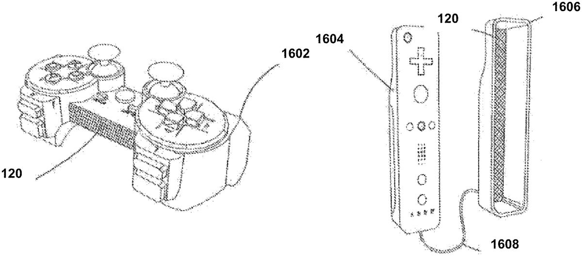
Various embodiments of the receiver120are also illustrated and described herein. For example, an embodiment of the receiver120is connected to a wireless power tool (e.g., as shown inFIGS. 6A-6Cand described below), another embodiment of the receiver120is embedded in a military uniform (e.g., as shown inFIGS. 10A-10Band described below), and yet another embodiment of the receiver120is embedded in medical devices (e.g., as shown inFIGS. 18A-18Cand described below). Various other examples are provided below.
FIG. 2provides an example flowchart of a process for wireless power transmission, in accordance with some embodiments.
In a first step201, a transmitter102(TX) establishes a connection or otherwise associates with a receiver120(RX). That is, in some embodiments, transmitters and receivers may communicate with one another over a wireless communication protocol capable of transmitting information between two processors of electrical devices (e.g., BLUETOOTH, BLUETOOTH Low Energy (BLE), WI-FI, NFC, ZIGBEE). For example, in embodiments implementing BLUETOOTH or BLUETOOTH variants, the transmitter may scan for receivers broadcasting advertisement signals or a receiver may transmit an advertisement signal to the transmitter. The advertisement signal may announce the receiver's presence to the transmitter, and may trigger an association between the transmitter and the receiver. As described herein, in some embodiments, the advertisement signal may communicate information that may be used by various devices (e.g., transmitters, client devices, server computers, other receivers) to execute and manage pocket-forming procedures. Information contained within the advertisement signal may include a device identifier (e.g., MAC address, IP address, UUID), the voltage of electrical energy received, client device power consumption, and other types of data related to power transmission. The transmitter may use the advertisement signal transmitted to identify the receiver and, in some cases, locate the receiver in a two-dimensional space or in a three-dimensional space. Once the transmitter identifies the receiver, the transmitter may establish the connection associated in the transmitter with the receiver, allowing the transmitter and receiver to communicate control signals over a second channel. The advertising signal is an example of the communication signal118(FIG. 1).
In a next step203, the transmitter may use the advertisement signal to determine waveform characteristics (discussed above) for transmitting the power transmission signals, to then establish the pockets of energy. The transmitter may use information contained in the receiver's advertisement signal, or in subsequent control/feedback signals received from the receiver, to determine how to produce and transmit the power transmission signals so that the receiver may receive the power transmission signals. In some cases, the transmitter may transmit power transmission signals in a way that establishes a pocket of energy, from which the receiver may harvest electrical energy. In some embodiments, the transmitter may include a processor104executing software modules capable of automatically identifying the power transmission signal features needed to establish a pocket of energy based on information received from the receiver, such as the voltage of the electrical energy harvested by the receiver from the power transmission signals. It should be appreciated that in some embodiments, the functions of the processor and/or the software modules may be implemented in an Application Specific Integrated Circuit (ASIC).
Additionally or alternatively, in some embodiments, the advertisement signal or a subsequent signal transmitted by the receiver over a second communications channel may indicate one or more waveform characteristics (also referred to herein as power transmission signals features), which the transmitter may then use to produce and transmit power transmission signals to establish a pocket of energy. For example, in some cases the transmitter may automatically identify the phase and gain necessary for transmitting the power transmission signals based on the location of the device and the type of device or receiver; and, in some cases, the receiver may inform the transmitter of the phase and gain for effectively transmitting the power transmission signals.
In a next step205, after the transmitter determines the appropriate waveform characteristics to use when transmitting the power transmission signals, the transmitter may begin transmitting power transmission signals, over a separate channel from the signals (e.g., power waves116are distinct from the communication signals118,FIG. 1). Power transmission signals may be transmitted to establish a pocket of energy. The transmitter's antenna elements may transmit the power transmission signals such that the power transmission signals converge in a two-dimensional or three-dimensional space around the receiver. The resulting field around the receiver forms a pocket of energy from which the receiver may harvest electrical energy. One antenna element may be used to transmit power transmission signals to establish two-dimensional energy transmissions; and in some cases, a second or additional antenna element may be used to transmit power transmission signals in order to establish a three-dimensional pocket of energy. In some cases, a plurality of antenna elements may be used to transmit power transmission signals in order to establish the pocket of energy. Moreover, in some cases, the plurality of antennas may include all of the antennas in the transmitter; and, in some cases, the plurality of antennas may include a number of the antennas in the transmitter, but fewer than all of the antennas of the transmitter. Various techniques for transmitting power transmission signals are discussed in further detail above with reference toFIG. 1.
As previously mentioned, the transmitter102may produce and transmit power transmission signals, according to a determined set of power transmission signal features. In some embodiments, the power transmission signals are produced and transmitted using an external power source and a local oscillator chip comprising a piezoelectric material. The transmitter may include a controller circuit (e.g., an RFIC) that controls production and transmission of the power transmission signals based on information related to power transmission and pocket-forming received from the receiver. This control data may be communicated over a different channel from the power transmission signals, using wireless communications protocols, such as BLE, NFC, or ZIGBEE®. The RFIC of the transmitter may automatically adjust the phase and/or relative magnitudes of the power transmission signals as needed. Pocket-forming is accomplished by the transmitter transmitting the power transmission signals in a manner that forms constructive interference patterns.
In a next step207, the receiver may harvest or otherwise receive electrical energy from the power transmission signals of a single beam or a pocket of energy. The receiver may include a rectifier and AC/DC converter (e.g., power converters126,FIG. 1), which may convert the electrical energy from AC current to DC current, and the rectifier of the receiver may then rectify the electrical energy, resulting in usable electrical energy for a client device associated with the receiver, such as a laptop computer, smartphone, battery, toy, or other electrical device. The receiver may utilize the pocket of energy produced by the transmitter during pocket-forming to charge or otherwise power the electronic device. Receiving the power transmission signals is discussed in further detail above with reference toFIG. 1.
In next step210, the receiver may generate data containing information indicating the effectiveness of the single beam or energy pockets providing the receiver power transmission signals. The receiver may then transmit control/feedback signals containing the data to the transmitter. The control/feedback signal is an example of the communication signals118. The control signals may be transmitted intermittently, depending on whether the transmitter and receiver are communicating synchronously (i.e., the transmitter is expecting to receive control data from the receiver). Additionally, the transmitter may continuously transmit the power transmission signals to the receiver, irrespective of whether the transmitter and receiver are communicating control signals. The data may contain information related to transmitting power transmission signals and/or establishing effective pockets of energy. Some of the information in the control data may inform the transmitter how to effectively produce and transmit, and in some cases adjust, the features of the power transmission signals. The control signals may be transmitted and received over a second channel, independent from the power transmission signals, using a wireless protocol capable of transmitting control data related to power transmission signals and/or pocket-forming, such as BLE, NFC, WI-FI, or the like.
As mentioned, the data may contain information indicating the effectiveness of the power transmission signals of the single beam or establishing the pocket of energy. The data may be generated by a processor of the receiver monitoring various aspects of the receiver and/or the client device associated with the receiver. The data may be based on various types of information, such as the voltage of electrical energy received from the power transmission signals, the quality of the power transmission signals reception, the quality of the battery charge or quality of the power reception, and location or motion of the receiver, among other types of information useful for adjusting the power transmission signals and/or pocket-forming.
In some embodiments, a receiver may determine the amount of power being received from power transmission signals transmitted from the transmitter and may then indicate that the transmitter should “split” or segment the power transmission signals into less-powerful power transmission signals. The less-powerful power transmission signals may be bounced off objects or walls nearby the device, thereby reducing the amount of power being transmitted directly from the transmitter to the receiver.
In a next step211, the transmitter may calibrate the antennas transmitting the power transmission signals, so that the antennas transmit power transmission signals having a more effective set of features (e.g., direction, phase, gain, amplitude). In some embodiments, a processor of the transmitter may automatically determine more effective features for producing and transmitting the power transmission signals based on the signal(s) received from the receiver. The transmitter may then automatically reconfigure the antennas to transmit recalibrated power transmission signals according to the newly determined more-effective features. For example, the processor of the transmitter may adjust gain and/or phase of the power transmission signals, among other features of power transmission feature, to adjust for a change in location of the receiver, after a user moved the receiver outside of the three-dimensional space where the pocket of energy is established.
FIG. 3provides an example flowchart of a process for wirelessly powering a plurality of receivers, in accordance with some embodiments. For the sake of brevity, features already described above with reference toFIGS. 1 and 2are not repeated here.
In a first step301, a transmitter102(TX) establishes a connection or otherwise associates with a receiver120(RX), as discussed above. The transmitter may scan for receivers broadcasting advertisement signals or a receiver may transmit an advertisement signal to the transmitter. The advertisement signal may announce the receiver's presence to the transmitter, and may trigger an association between the transmitter and the receiver.
Next, in step303, when the transmitter detects the advertisement signal, the transmitter may automatically form a communication connection with that receiver, which may allow the transmitter and receiver to communicate control signals and power transmission signals. The transmitter may then command that receiver to begin transmitting real-time sample data or other data. The transmitter may also begin transmitting power transmission signals from antennas of the transmitter's antenna array.
In a next step305, the receiver may then measure the voltage, among other metrics related to effectiveness of the power transmission signals, based on the electrical energy received by the receiver's antennas. The receiver may generate data containing the measured information, and then transmit control signals (e.g., communication signals118,FIG. 1) containing the data to the transmitter. For example, the receiver may sample the voltage measurements of received electrical energy, for example, at a rate of 100 times per second. The receiver may transmit the voltage sample measurement back to the transmitter, 100 times a second, in the form of control signals.
In a next step307, the transmitter may execute one or more software modules monitoring the metrics, such as voltage measurements, received from the receiver. Algorithms may vary production and transmission of power transmission signals by the transmitter's antennas, to maximize the effectiveness of the pockets of energy around the receiver. For example, the transmitter may adjust the phase at which the transmitter's antennas transmit the power transmission signals, until that power received by the receiver indicates establishment of a pocket of energy around the receiver. When an optimal configuration for the antennas is identified, memory106of the transmitter may store the configurations to keep the transmitter broadcasting at that highest level.
In a next step309, algorithms of the transmitter may determine when it is necessary to adjust the power transmission signals and may also vary the configuration of the transmit antennas, in response to determining such adjustments are necessary. For example, the transmitter may determine the power received at a receiver is less than maximal, based on the data received from the receiver. The transmitter may then automatically adjust the phase of the power transmission signals, but may also simultaneously continue to receive and monitor the voltage being reported back from receiver.
In a next step311, after a determined period of time for communicating with a particular receiver, the transmitter may scan and/or automatically detect advertisements from other receivers that may be in range of the transmitter. The transmitter may establish a connection to the second receiver responsive to, e.g., BLUETOOTH advertisements, from a second receiver.
In a next step313, after establishing a second communication connection with the second receiver, the transmitter may proceed to adjust one or more antennas in the transmitter's antenna array. In some embodiments, the transmitter may identify a subset of antennas to service the second receiver, thereby parsing the array into subsets of arrays that are associated with a respective receiver. In some embodiments, the entire antenna array may service a first receiver for a given period of time, and then the entire array may service the second receiver for that period of time.
Manual or automated processes performed by the transmitter may select a subset of arrays to service the second receiver. In this example, the transmitter's array may be split in half, forming two subsets. As a result, half of the antennas may be configured to transmit power transmission signals to the first receiver, and half of the antennas may be configured for the second receiver. In the current step313, the transmitter may apply similar techniques discussed above to configure or optimize the subset of antennas for the second receiver. While selecting a subset of an array for transmitting power transmission signals, the transmitter and second receiver may be transmitting and receiving data. As a result, by the time that the transmitter alternates back to communicating with the first receiver and/or scan for new receivers, the transmitter has already received a sufficient amount of sample data to adjust the phases of the waves transmitted by the second subset of the transmitter's antenna array to transmit power transmission waves to the second receiver effectively.
In a next step315, after adjusting the second subset to transmit power transmission signals to the second receiver, the transmitter may alternate back to communicating data with the first receiver, or scanning for additional receivers. The transmitter may reconfigure the antennas of the first subset, and then alternate between the first and second receivers at a predetermined interval.
In a next step317, the transmitter may continue to alternate between receivers and scanning for new receivers, at a predetermined interval. As each new receiver is detected, the transmitter may establish a connection and begin transmitting power transmission signals, accordingly.
In one example embodiment, the receiver may be electrically connected to a device like a smart phone. The transmitter's processor would scan for any BLUETOOTH devices. The receiver may begin advertising that it's a BLUETOOTH device through the BLUETOOTH chip (e.g., broadcasting advertising signals). The advertising signal may include unique identifiers so that the transmitter, when it scanned that advertisement, could distinguish that advertisement and ultimately that receiver from all the other BLUETOOTH devices nearby within range. When the transmitter detects that advertisement and notices it is a receiver, then the transmitter may immediately form a communication connection with that receiver and command that receiver to begin sending real time sample data.
The receiver would then measure the voltage at its receiving antennas, and send that voltage sample measurement back to the transmitter (e.g., 100 times a second). The transmitter may start to vary the configuration of the transmit antennas by adjusting the phase. As the transmitter adjusts the phase, the transmitter monitors the voltage being sent back from the receiver. In some implementations, the higher the voltage, the more energy may be in the pocket. The antenna phases may be altered until the voltage is at the highest level and there is a maximum pocket of energy around the receiver. The transmitter may keep the antennas at the particular phase so the voltage is at the highest level.
The transmitter may vary each individual antenna, one at a time. For example, if there are 32 antennas in the transmitter, and each antenna has 8 phases, the transmitter may begin with the first antenna and would step the first antenna through all 8 phases. The receiver may then send back the power level for each of the 8 phases of the first antenna. The transmitter may then store the highest phase for the first antenna. The transmitter may repeat this process for the second antenna, and step it through 8 phases. The receiver may again send back the power levels from each phase, and the transmitter may store the highest level. Next the transmitter may repeat the process for the third antenna and continue to repeat the process until all 32 antennas have stepped through the 8 phases. At the end of the process, the transmitter may transmit the maximum voltage in the most efficient manner to the receiver.
In another example embodiment, the transmitter may detect a second receiver's advertisement and form a communication connection with the second receiver. When the transmitter forms the communication with the second receiver, the transmitter may aim the original 32 antennas towards the second receiver and repeat the phase process for each of the 32 antennas aimed at the second receiver. Once the process is completed, the second receiver may receive as much power as possible from the transmitter. The transmitter may communicate with the second receiver for a period of time (e.g., a second), and then alternate back to the first receiver for a period of time (e.g., a second), and the transmitter may continue to alternate back and forth between the first receiver and the second receiver at the time period intervals.
In yet another implementation, the transmitter may detect a second receiver's advertisement and form a communication connection with the second receiver. First, the transmitter may communicate with the first receiver and re-assign half of the example 32 the antennas aimed at the first receiver, dedicating only 16 towards the first receiver. The transmitter may then assign the second half of the antennas to the second receiver, dedicating 16 antennas to the second receiver. The transmitter may adjust the phases for the second half of the antennas. Once the 16 antennas have gone through each of the 8 phases, the second receiver may be receiving the maximum voltage in the most efficient manner.
FIGS. 4A-4Dillustrate in-vehicle wireless power transmission systems, in accordance with some embodiments.
Referring toFIG. 4A, a wireless power transmitter system400can be implemented in order to charge or power one or more electronic devices401(e.g., an embodiment of the electronic device122,FIG. 1) inside a vehicle. According to some aspects of this embodiment, transmitter102can be configured within a cylindrical shape, exhibiting a longitude between about 2 and 3 inches, and a diameter ranging from about 0.5 inch to about 1 inch. As illustrated in close-up view402, transmitter102can include a suitable connector404with pins406that can be inserted into car lighter socket408for powering transmitter102. Transmitter102can function as a standalone, self-contained device that can integrate circuitry module414and antenna array412(e.g., an embodiment of the antenna array110,FIG. 1), along with connector404and pins406.
Car lighter socket408can supply 12 or 24 DC volts for powering transmitter102, which may be sufficient power for most portable electronic devices401such as smartphones, DVD players, portable gaming systems, tablets, laptops computers, and the like. In some embodiments, circuitry module414of transmitter102can include a DC-to-DC converter or a DC-to-AC converter, depending on the electrical charging requirements of electronic device401. Yet in other embodiments, circuitry module414can include a switchable power converter that can be configured according to the charging requirements of electronic device401.
Operation of transmitter102inFIG. 4Acan be driven by a power source, in this case, car lighter socket308. Transmitter102can use communication component112(not shown inFIG. 4A) in circuitry module414to locate a receiver120(not shown inFIG. 4A) embedded in electronic device401. Processor(s)104(not shown inFIG. 4A) which may be included in circuitry module414of the transmitter102may determine the optimum path for the generation of pocket-forming, according to the location of electronic device401within the vehicle. As depicted inFIG. 4A, electronic device401can be located in the passenger seat, right beside the driver seat. Processors104may communicate with a radio frequency integrated circuit in circuitry module414so as to control the generation and transmission of RF waves116through antenna array412which may include two or more antenna elements. Transmission of RF waves116can be aimed at electronic device401in the passenger seat for the generation of pocket-forming suitable for charging or powering electronic device401.
The wireless power transmission system400can also be used for powering or charging an electronic device401located in the backseats of the vehicle, or any other locations inside vehicle. In this case, transmitter102can use any suitable reflecting surface of the vehicle, preferably metallic, in order to transmit RF waves116and redirect the formation of pockets of energy towards electronic device401, with minimal or no power loss. For example, transmitter102can use the vehicle ceiling to bounce off transmitted RF waves116towards electronic device401for the generation of pockets of energy capable of providing suitable charging or powering to electronic device401.
In some embodiments, the wireless power transmission400powers or charges two or more electronic devices401inside vehicle, where transmitter102can be capable of producing multiple pocket forming. In such case, transmitter102can generate multiple RF waves116directly aimed at or reflected towards electronic devices401through the use of suitable reflecting surfaces of the vehicle, thereby powering or charging one or more electronic devices401at the same time.
FIG. 4Billustrates a wireless power transmission system420where transmitter102includes a cable422for positioning antenna array412in different areas inside a vehicle. As seen in close-up view421, transmitter102, through the use of connector404and pins406, can be connected to car lighter socket408to receive power necessary for operation. According to some aspects of this embodiment, circuitry module414of transmitter102can be operatively coupled with car lighter socket408, while antenna array412can be operatively connected with circuitry module414through cable422, thereby allowing antenna array412to be separately positioned across vehicle, as required by the application or according to the relative position of one or more electronic devices401. For example, as shown inFIG. 4B, cable422can be run from circuitry module414to antenna array412which can be slipped in one of the vehicle's sun visor424. In this way, antenna array412can emit RF waves116from a high-up position down to one or more electronic devices401for the generation of pockets of energy that may provide suitable charging or powering. This configuration may be particularly beneficial for charging or powering electronic devices401in the vehicle's backseats.
Antenna array412inFIG. 4Bcan exhibit a flat rectangular shape, with dimensions between about 4×2 inches to about 8×4 inches, depending on the number and configuration of antenna elements412. Cable422can include a suitable conductor covered by an insulating material, it may be flexible and may exhibit a suitable length as required by the application. Preferably, cable422can be positioned between circuitry module414of transmitter102and antenna array412in such a way as to not obstruct the visibility of the windshield, as illustrated inFIG. 4B.
Referring now toFIG. 4C, a wireless power transmission system430includes a transmitter102with its circuitry module414connected to car lighter socket408, while its antenna array412can be positioned on the vehicle's floor432. Similarly as inFIG. 4B, antenna array412may exhibit a flat rectangular shape with dimensions between about 4×2 inches to about 8×4 inches, depending on the number and configuration of antenna elements. According to some aspects of this embodiment, antenna array412can be covered by the vehicle floor mats (not shown inFIG. 4C), where this antenna array412can emit RF waves116from the bottom of the vehicle floor432upwards to one or more electronic devices401that may be positioned in the passenger seat, as illustrated inFIG. 4C, or in any another suitable location within the vehicle.
Similarly as inFIG. 4B, cable422can operatively connect circuitry module414(not shown inFIG. 4C) to antenna array412for the transmission of RF waves116that may produce pockets of energy suitable for charging or powering one or more electronic devices401inside the vehicle. In this particular embodiment, antenna array412may include a suitable combination of flexible and conducting materials that may allow transmission of RF waves116, while avoiding fractures or breakdown when a passenger steps on antenna array412placed underneath the vehicle's floor432mats.
Although these example embodiments of wireless power transmission may describe transmitter102as a standalone device that may be connected to a car lighter socket408, including the different configurations and positions for its antenna array412, other transmitter102configurations and features may be contemplated as well. For example, antenna array412of transmitter102may be positioned in any suitable areas inside the vehicle such as passenger seats and backseats, storage compartments, and center console among others. In other embodiments, transmitter102may be configured as a built-in device that may be factory-integrated in suitable areas or parts of the vehicle such as sun-visors, sunroofs, sound speakers, dashboards, and the like.
FIG. 4Dshows a simplified flowchart of a wireless power transmission process440that may be implemented for charging one or more electronic devices401inside a vehicle. This process may be applicable in the embodiments of the wireless power transmission systems400,420, and430.
The wireless power transmission process440may begin with a wireless charging request, at block442. Subsequently, transmitter102may perform a BLUETOOTH scanning for identifying any suitable electronic device401that may require wireless charging or powering, at block444. Specifically, this BLUETOOTH scanning may be carried out by a communication component integrated in circuitry module414of transmitter102.
Using BLUETOOTH scanning, transmitter102may determine if there are one or more electronic devices401available for charging or powering, at block446. Basically, any suitable electronic device401operatively coupled with a receiver120and capable of BLUETOOTH communication may be considered “available” for wireless charging or powering. If there are no available electronic devices401for wireless charging or powering, then BLUETOOTH scanning can be repeated until there is at least one electronic device401available. If one or more electronic devices401are available, then wireless power transmission process440may continue at block448, where one or more electronic devices401may log into a charging application developed in any suitable operating systems such as iOS, ANDROID, and WINDOWS, among others. This charging application may establish a suitable communication channel between transmitter102and electronic device401, where configuration of transmitter102can be accessed and reprogrammed according to the charging or powering requirements of electronic devices401.
One or more electronic devices401may access the charging application in order to modify the configuration of transmitter102. Specifically, one or more electronic devices401can communicate with transmitter102via BLUETOOTH and log into the charging application to set up charging or powering priorities as necessary, at block450. For example, in a long family trip, charging or powering priorities can be established to first charge or power-up electronic devices401for kids' entertainment such as portable gaming consoles and tablets, followed by the charging or powering of parents' electronic devices401such as smartphones and laptops. Other transmitter102parameters such as power intensity and pocket-forming focus/timing can also be modified through the use of this charging application. However, authorization access to transmitter102configuration may be restricted to certain users who may be required to provide corresponding user-credentials and passwords.
After charging priorities in transmitter102are set, transmission of RF waves116towards the designated electronic devices401can begin, at block452, where these RF waves116may generate pockets of energy at receivers120for powering or charging one or more electronic devices401sequentially or simultaneously. In other embodiments, different charging or powering thresholds may be established for maintaining suitable operation. For example, minimum and maximum charging thresholds may be established at about 20% and 95% of total charge respectively, where charging or powering of electronic devices401may be stopped when reaching 95% of total charge, and may resume when total charge of electronic devices401falls below 20%.
BLUETOOTH scanning may continue throughout the process in order to identify additional electronic devices401that may require wireless charging or powering, at block454. If new or additional electronic devices401are identified, then transmitter102may be accessed through the charging application to set charging or powering priorities for these additional electronic devices401. If no further electronic devices401are recognized by BLUETOOTH scanning, then wireless power transmission process440may end, at block456.
FIGS. 4A-4Dillustrate examples of or relate to the wireless power transmission environment100described above with reference toFIG. 1. For the sake of brevity, certain details related to techniques for wirelessly delivering power described above in reference toFIG. 1are not repeated here, as one of skill in the art will appreciate that these techniques apply to the embodiments ofFIGS. 4A-4D.
Presented below are example methods of wirelessly delivering power to receivers in a vehicle.
In some embodiments, an example method includes defining, by a transmitter, a pocket of energy positioned within a vehicle, and the vehicle includes the transmitter and a power source powering the transmitter. The method further includes charging, by the transmitter, an electronic device positioned within the vehicle, and the electronic device includes a receiver that interfaces with the pocket of energy in the vehicle.
In some embodiments, the power source includes at least one of a vehicle lighter socket and a direct connection to a power wire within the vehicle.
In some embodiments, the electronic device is a first electronic device and the transmitter charges a second electronic device positioned within the vehicle based on the second device interfacing with the pocket of energy in the vehicle.
In some embodiments, another example method includes scanning, using a wireless communication component of a transmitter, for available receivers within a vehicle that are authorized to receive wirelessly delivered power from the transmitter and detecting, by the transmitter, a first receiver and a second receiver of the available receivers within the vehicle based on the scanning. The method further includes, while continuing to scan for available receivers within the vehicle: (i) receiving, by a connector of the transmitter, where the connector is coupled to a power source of the vehicle, electrical current from the power source that is used by the transmitter to generate a plurality of power waves, (ii) receiving, by the wireless communication component of the transmitter, a charging request from the second receiver within the vehicle, (iii) adjusting, by a controller of the transmitter, respective gains and phases of at least a second set of the plurality of power waves, and (iv) transmitting the second set of the plurality of power waves such that the second set of the plurality of power waves converge to form a second constructive interference pattern, distinct from the first constructive interference pattern, in proximity to a location of the second receiver within the vehicle.
In some embodiments, the charging request (i) corresponds to a request for wirelessly delivered power from the transmitter, and (ii) is sent by the second receiver when a charge level of the second receiver is less than a minimum level of charge.
FIGS. 5A-5Dillustrate additional embodiments of wireless power transmission systems associated with vehicles, in accordance with some embodiments.
FIG. 5Aillustrates a wireless power transmission system500where a transmitter102may provide wireless power, through pocket-forming, to sensors in the bottom part of a car502. Transmitter102can be placed in the bottom of car502, and may power, for example, tire pressure gauges, brake sensors and the like. The foregoing gauges and sensors may include embedded or otherwise operatively coupled receivers (not shown) (e.g., an embodiment of the receiver120,FIG. 1) for converting pockets of energy into usable energy. Even though the paths of RF waves504appear to be in straight lines, transmitter102can bounce RF waves504off of suitable reflecting areas of car502to improve power delivery efficiency. One of the main advantages of the foregoing disclosed configuration of the wireless power transmission system500may be the cost-effective solution of eliminating the wires required for powering the aforementioned sensors in the bottom of car502.
FIG. 5Billustrates a wireless power transmission system510where a transmitter102may provide wireless power, through pocket-forming, to sensors in the engine compartment of a car502. Transmitter102can be placed in the bottom internal surface of a hood512(or other suitable locations) of car502in order to power engine sensors such as throttle position sensors, engine coolant temperature sensors, barometric sensors and the like. The transmitter102can use reflecting areas from the engine compartment of car502to bounce off RF waves504(e.g., power waves116,FIG. 1) to improve power delivery efficiency. In some embodiments, transmitter102can be used to power the sensors present in typical alarm systems, for example, door sensors, pressure sensors (for the interior of car502), shock sensors and the like. In other embodiments, transmitter102can function as an alternate or main power supply for alarm speakers514.
FIG. 5Cillustrates a wireless power transmission system520where a transmitter102may provide wireless power, through pocket-forming, to sensors, gauges or small miscellaneous devices in the interior of a car502. In some embodiments, transmitter102can be placed in the instrument panel (not shown) of car502. In this particular embodiment, transmitter102is shown to be powering a rear window defroster522of car504, and thus diminishing the need for wires. In some embodiments, transmitter102can provide power to the actuators in the car windows, and even to the interior lighting system.
FIG. 5Dillustrates a wireless power transmission system530where a transmitter102may provide wireless power, through pocket-forming, to devices in the interior of car502. In this embodiment, transmitter102can provide wireless power to speakers532while eliminating the use of wires.
FIGS. 5A-5Dillustrate examples of or relate to the wireless power transmission environment100described above with reference toFIG. 1. For the sake of brevity, certain details related to techniques for wirelessly delivering power described above in reference toFIG. 1are not repeated here, as one of skill in the art will appreciate that these techniques apply to the embodiments ofFIGS. 5A-5D.
Presented below are example systems and methods of wirelessly delivering power to receivers on or within a vehicle.
In some embodiments, an example method includes defining, by a transmitter, a pocket of energy within a vehicle via a plurality of wireless power transmission waves emitted by the transmitter, the vehicle including the transmitter, a receiver, and a vehicle sensor coupled to the receiver. The method further includes interfacing, by the receiver, with the pocket of energy within the vehicle, and providing, by the receiver, power to the vehicle sensor based on the interfacing.
In some embodiments, the vehicle includes a bottom portion, and the transmitter is located in the bottom portion. The sensor is at least one of a tire pressure sensor and a brake sensor.
Alternatively or in addition, in some embodiments, the vehicle includes an engine compartment and the transmitter is located in the engine compartment. In such embodiments, the sensor is an engine sensor.
In some embodiments, an example system includes a vehicle, one or more sensors coupled to the vehicle, and a transmitter coupled to the vehicle (e.g., an exterior of the vehicle). The vehicle is configured to power the transmitter and the transmitter is configured to define a pocket of energy within the vehicle via a plurality of wireless power transmission waves emitted by the transmitter. The system further includes a receiver coupled to the vehicle. The sensor is coupled to the receiver and the receiver is configured to power the sensor by interfacing with the pocket of energy.
FIGS. 6A-6Dprovide examples of wireless power transmission for wirelessly delivering power to cordless power tools, in accordance with some embodiments.
Referring toFIG. 6A, a wireless power transmission system600may include a transmitter102embedded in a toolbox602to wirelessly charge or power one or more cordless power tools604, according to an embodiment. Toolbox602may be capable of storing and transporting a plurality of cordless power tools604and other related tools or components. Transmitter102may be embedded in a region or area of toolbox602suitable for transmitting RF waves116towards receiver120which may be attached or operatively coupled to the battery606of cordless power tool604. For example, transmitter102may be positioned at the top right corner of toolbox602housing to direct RF waves116towards receiver120for the generation of pockets of energy capable of wirelessly charging the battery606of cordless power tool604. The cordless power tool604may be an example of the electronic device122.
Toolbox602may also include a battery603which may be operatively coupled with transmitter102through a cable (not shown) for allowing the generation and transmission of RF waves116as required by the application. Simply put, battery603may function as a power source for transmitter102. In some embodiments, toolbox602may be connected to an external power source608to charge battery603through a suitable cable610, while simultaneously powering transmitter102for the generation and transmission of RF waves116directed towards receiver120, which can be embedded or attached to cordless power tool604. External power source608source may include a 120/220 AC volt outlet, in which case toolbox602may include a suitable AC/DC converter (not shown) for converting AC voltage and supplying DC voltage to battery603for charging.
In another embodiment, when battery603is charged to a suitable level, toolbox602may be disconnected from external power source608, and subsequently carried and positioned in a desired working area where cordless power tool604may be used. In this case, transmitter102may receive power for the generation and transmission of RF waves116solely and directly from battery603. Charged battery603in toolbox602may provide enough charge to transmitter102for the generation of pockets of energy within a power range of about 1 watt to about 5 watts, and within a working distance of about 5 ft. to about 20 ft. These power levels of pocket of energy may be suitable for charging the battery606of cordless power tool604while in use, or at least extending the life of battery606during operation. In general, the power and range of the generated RF waves116may vary according to the number of antenna elements, distribution, and size of transmitter102. A cordless power tool604not in use or in standby can also be charged by a transmitter102embedded in toolbox602.
FIG. 6Bshows another configuration of the wireless power transmission system600. In this configuration, the portable toolbox602may be located on or within a vehicle612, according to an embodiment. Vehicle612may be a private car or a service van commonly used by technicians having to perform field work or related activities. Similarly as inFIG. 6A, toolbox602may be connected to external power source608for charging battery603and powering transmitter102. External power source608, in this case, may be the battery of vehicle612. Toolbox602may be operatively coupled to external power source608through a suitable connection that includes a car lighter socket614and cable616. In order to avoid draining the battery of vehicle612, engine618may be on or running when charging battery603or powering transmitter102in toolbox602. In some embodiments, transmitter102may generate and direct RF waves116towards the receivers120embedded or attached to one or more cordless power tools604for the wireless charging of batteries112. Transmitter102in toolbox602may wirelessly charge or power two or more cordless power tools604simultaneously or sequentially according to the power or application requirements. Transmitter102in toolbox602may also charge a spare battery620having a suitable receiver120attached.
In some embodiments, when battery603in toolbox602is charged to a suitable level, toolbox602can be disconnected from the car lighter socket614and placed at a location outside vehicle612. Transmitter102in toolbox602may subsequently generate RF waves116which may wirelessly charge or at least extend the life of batteries606during the operation of cordless power tools604, in this case, transmitter102may be energized directly from the charged battery603in toolbox602. In some embodiments, a surface area of the antenna array110(FIG. 1) of the transmitter102embedded in toolbox602may range from approximately 2 in2to about 12 in2depending on the dimensions of toolbox602.
FIG. 6Cillustrates an additional configuration of wireless power transmission system600. In this configuration, transmitter102may be configured in the doors or windows of vehicle612, according to an embodiment. Specifically, the antenna array of transmitter102may be configured to fit one window of vehicle612. In such a case, the antenna array may include between about 300 and about 600 antenna elements distributed within a surface area that may vary between about 90 in2and about 160 in2. This increased number of antenna elements and footprint of transmitter102may allow for a higher level of power distribution and reach of the emitted RF waves116as compared to the embodiment shown inFIG. 6B. For example, transmitter102within the specified dimensions and number of antenna elements may emit RF waves116capable of generating a pocket of energy between about 1 Watt and 10 Watts of power, and within a distance of about 30 ft and about 50 ft.
InFIG. 6C, transmitter102may be constantly and directly connected to an external power source608such as vehicle612battery via car lighter socket614and cable616. Engine618may be on or running when transmitter102is in operation in order to prevent draining of the vehicle's612battery. Transmitter102may generate and direct RF waves116towards the receivers120embedded or attached to one or more cordless power tools604for the charging of batteries606. Transmitter102may wirelessly charge or power two or more cordless power tools604simultaneously or sequentially according to the power or application requirements. Transmitter102may also wirelessly charge a spare battery620having a suitable receiver120attached.
FIG. 6Dshows a flowchart of a wireless power transmission process630that may be implemented for charging one or more cordless power tools604using toolbox602as a portable device. This process may be applicable to the embodiments of wireless power transmission systems600shown inFIGS. 6A-6C.
Wireless power transmission process630may begin by checking the charge levels of battery603embedded in toolbox602, at block632. This charge check may be performed by a control module included in toolbox602(not shown inFIGS. 6A-6B) or by micro-controller (e.g., processor104,FIG. 1) in transmitter102, which may be operatively connected to battery603. Different charging levels for battery603may be established for maintaining suitable operation. For example, minimum and maximum charging thresholds may be established at about 25% and 99% of total charge respectively. At block634, if battery603charge is below the minimum threshold or 25%, then toolbox602can be connected to external power source608using cable610, where external power source608may include vehicle612battery or a standard 120/220 AC volts outlet as explained inFIGS. 6A-6B. When battery603charge is at 99% or at least above 25%, toolbox602can be disconnected from external power source608, at block436.
If battery603is charged to a suitable level, specifically between about 25% and about 99%, then wireless power transmission process630may continue at block638, where communications component112in transmitter102may identify one or more cordless power tools604that may require wireless charging. Charging or powering priorities and other parameters such as power intensity and pocket-forming focus/timing may be established using a control module included in toolbox602or micro-controller in transmitter102. For example, based on charging or powering priorities, transmitter102may be configured to first provide wireless charging to cordless power tools604in use, followed by cordless power tools604in standby, and lastly to spare batteries620.
After cordless power tools604are identified and charging priorities/parameters in transmitter102are set, transmission of RF waves116towards the designated cordless power tools604or spare batteries620can begin, at block640, where these RF waves116may generate pockets of energy at receivers120for powering or charging one or more cordless power tools604and spare batteries620sequentially or simultaneously.
Using communications component112, transmitter102in toolbox602may continuously check if there are other cordless power tools604or spare batteries620that may require wireless charging or powering, at block642. If new or additional cordless power tools604or spare batteries620are identified, then transmitter102in toolbox602may wirelessly charge the identified cordless power tools604and spare batteries620according to the established charging priorities and parameters. If no further cordless power tools604are recognized by communications component112in transmitter102, then wireless power transmission process630may end.
FIGS. 6A-6Dillustrate examples of or relate to the wireless power transmission environment100described above with reference toFIG. 1. For the sake of brevity, certain details related to techniques for wirelessly delivering power described above in reference toFIG. 1are not repeated here, as one of skill in the art will appreciate that these techniques apply to the embodiments ofFIGS. 6A-6D.
Presented below are example methods of wirelessly delivering power to cordless power tools.
In some embodiments, an example method includes establishing, by a transmitter, a connection with a power source; generating, by the transmitter, a plurality of power transmission waves to form a pocket of energy; receiving, by the transmitter, a transmission of a power requirement of a cordless power tool and a receiver location; and transmitting, by the transmitter, the power transmission waves through at least two antennas coupled to the transmitter in response to the received transmission.
In some embodiments, the transmitter establishes communication with the receiver when the cordless power to the cordless power tool is within a predetermined distance (e.g., a distance of 10 feet or less) from the transmitter.
In some embodiments, another example method includes establishing, by a transmitter that is coupled to at least two antennas for transmitting power transmission waves to a plurality of cordless power tools, a connection with a power source that is used to charge a battery of the transmitter and determining, by the transmitter, whether the battery has a charge level that is above a threshold charge level. The method further includes, in accordance with determining that the battery has the charge level that is above the threshold charge level, identifying, by a communication component of the transmitter that is distinct from the at least two antennas of the transmitter, a cordless power tool of the plurality of cordless power tools that requires wireless charging. The method further includes receiving, by the communication component of the transmitter, information that identifies a power requirement of the cordless power tool and a location of a receiver that is coupled to the cordless power tool and transmitting, by the transmitter, a plurality of power transmission waves through the at least two antennas in response to the received information, and the plurality of power transmission waves are transmitted so that the plurality of power transmission waves converges to form a pocket of energy in proximity to the location of the receiver.
FIGS. 7A-7Billustrate wireless power transmission systems used in rescue situations, in accordance with some embodiments.
FIG. 7Ashows a configuration of wireless power transmission system700where a transmitter102may be located on or within a vehicle702, according to some embodiments. Vehicle702may be a rescue car, fire truck, ambulance and the like. Transmitter102may use a diesel generator704as power source210. However, other power sources may be employed too. Transmitter102may generate and direct RF waves116towards receivers120embedded or attached to rescue devices such as lamps, GPS, radios, cellphones, lights, among others. In addition, transmitter102in vehicle702may wirelessly extend the life of batteries in the previously mentioned devices during the operation.
Transmitter102may be located in a telescopic mast706, which may be lifted up for increased range of wireless powering. Furthermore, other transmitter102configurations may be used in dependency of the region and requirements, such requirements may include low profile transmitters for a higher stability of vehicle702during gales or winds with high speed.
FIG. 7Billustrates a disaster zone710, where a rescue vehicle702provides power and charge to a variety of rescue devices of a rescue team. Vehicle702may include a transmitter102located at the top of a telescopic mast706. RF waves116may be transmitted through obstacles and may be reflected on objects for reaching receivers120.
Receivers120may allow tracking of vehicle702, such a feature may allow the capacity to operate beyond the range of transmitter102through the charge on the batteries. When batteries have low charge, receivers120may guide its user to vehicle702in order to obtain charge.
Vehicle702may operate and reach sharper areas than vehicles with a wired power source, such capability is enabled through the wireless power transmission, which allows a higher mobility than cabled power sources.
FIGS. 7A-7Billustrate examples of or relate to the wireless power transmission environment100described above with reference toFIG. 1. For the sake of brevity, certain details related to techniques for wirelessly delivering power described above in reference toFIG. 1are not repeated here, as one of skill in the art will appreciate that these techniques apply to the embodiments ofFIGS. 7A-7B.
Presented below are example methods of wirelessly delivering power to rescue devices.
In some embodiments, an example method includes generating power RF signals from a RF circuit connected to the transmitter controlling the generated RF signals with a controller to provide a power RF signal and short RF communication signals; transmitting the power RF and short RF communication signals, through antenna elements connected to the transmitter, capturing power RF signals in a receiver with an antenna connected to the rescue electronic device to convert the pockets of energy into a DC voltage for charging or powering the rescue electronic device; and communicating power requirements of the rescue electronic device and the receiver location information between the pocket-forming transmitter and receiver with the short RF signals.
In some embodiments, the power source is a mobile diesel generator, a mobile gasoline generator or a vehicle generator or battery.
In some embodiments, the transmitter includes a housing suitable for field use, at least two antenna elements, at least one RF integrated circuit, at least one digital signal processor (DSP), and a communication component for generating the power RF and short RF signals.
In some embodiments, a telescopic mast connected to the transmitter is used to elevate the transmitter above the clutter at a rescue site.
In some embodiments, the method further includes extending the transmission distance of the pocket-forming transmitter by mounting the pocket-forming transmitter a predetermined height with the telescopic mast connected to a top surface of a vehicle including a fire truck, ambulance, rescue truck or other rescue vehicle.
In some embodiments, another example method includes, at a wireless power transmitter that includes a receiver antenna element, a radio frequency (RF) circuit, and a plurality of transmitter antenna elements, and the wireless power transmitter is connected to a power source and a telescoping mast of a mobile vehicle, the telescoping mast extending in a vertical direction above the mobile vehicle, receiving, via the receiver antenna element, a communication signal from a receiver device positioned at a location within a transmission range of the wireless power transmitter and controlling, via the RF circuit, operation of the plurality of transmitter antenna elements to generate wireless power transmission RF signals having predetermined phases and amplitudes using power from the power source. The method further includes transmitting and steering, via the RF circuit, the wireless power transmission RF signals via the plurality of transmitter antenna elements so that the wireless power transmission RF signals constructively interfere at the location.
FIG. 8Aillustrates an example embodiment of a multimode transmitter. Some elements of this figure are described above.
A multimode transmitter800, such as transmitter102, is configured to operate as or includes a wireless power router and/or a communication network router, whether in a serial manner, such as one at a time, or a parallel manner, such as concurrently. More particularly, transmitter800is configured to define a pocket of energy via a plurality of wireless power waves so that a first receiver is able to interface with the pocket of energy, as described herein. Transmitter800is configured to emit the wireless power waves, as described herein. For example, at least one of the wireless power waves can be based on a radio frequency.
Transmitter800is also configured to provide a network communication signal to a second receiver so that the second receiver is able to interface with the network signal (i.e., is able to access the Internet using the network signal). Such provision can be performed in a wired manner, such as via a cable, a wire-line, or others. Such provision can also be performed in a wireless manner, such as optical, radio, laser, sound, infrared, or others. Such provision can based at least in part on the transmitter receiving a unique identifier from the second receiver, such as a media access control (MAC) address. For example, the network signal includes at least one of an Ethernet signal, a WI-FI signal, an optical signal, a radio signal, an infrared signal, a laser signal, or another type of signal, whether via a short range communication protocol, such as BLUETOOTH, or via a long range communication protocol, such as a satellite signal or a cellular signal, such as a cell site. The network signal is based at least in part on a network, and the network is or includes at least one of a local area network (LAN), a wide area network (WAN), a storage area network (SAN), a backbone network, a metropolitan area network, a campus network, a virtual private network, a global area network, a personal area network (PAN), or others, whether for an intranet, an extranet, an internetwork, or darknet.
Transmitter800includes a plurality of antenna elements802, as described herein, and a radio frequency integrated circuit (RFIC). Antenna elements802and RFIC are arranged in a flat array arrangement, which reduces losses due a shorter distance between components. However, other types of arrangements are possible, such as non-flat, for instance, hemispherical. Transmitter800is configured to regulate a phase and an amplitude of pocket-forming operations in antenna elements802, as described herein. For example, such regulation can be via corresponding RFIC in order to generate a desired pocket-forming output and null-space steering. Furthermore, transmitter800can be configured so that multiple pocket-forming outputs may charge a higher number of receivers and allow a better wave trajectory to such receivers. Transmitter800can include an omnidirectional antenna.
In some embodiments, transmitter800includes or is coupled to a plurality of arrays comprising antenna elements802. Such coupling can be direct or indirect, wired or wireless, and/or local or remote. For example, such coupling can be via a wire spanning between transmitter800and at least one of such arrays. Note that such arrays can be embodied as one unit or a plurality of inter-coupled units or intra-coupled units. Such coupling can be direct or indirect, wired or wireless, and/or local or remote. For example, such coupling can be via a wire spanning between at least two of such arrays. Also, note that at least two of such arrays can be identical to each other or different from each based on at least one of structure, function, shape, size, coupling characteristics, or material properties. A presence of such arrays may increase or decrease a number of antenna elements802operating for each application, such as either for a wireless power transmission or a communication network signal transmission. In some embodiments, transmitter800lacks distinct array division, such as visual, such as into the first portion and the second portion. Resultantly, at least one of such arrays comprising antenna elements802operates for the communication network signal transmission only, and the switch, as described herein, changes an operational mode to enable the power router functionality. For example, transmitter800is configured to operate such that a first portion of an array, as described herein, such as a half, transmits the network signal, such as a WI-FI signal, and a second portion of the array, such as the other half, defines the pocket of energy, such as described herein. Line804represents a division in the array arrangement. Note that although the first portion and the second portion are symmetrical, the first portion and the second portion can be asymmetrical. Also, note that the first portion and the second portion can differ from each other or be identical to each other in at least one of a shape, a size, and a number of antenna elements802.
In some embodiments, transmitter800includes an antenna, as described herein. Therefore, transmitter800defines the pocket and provides the network signal via the antenna. Transmitter800can define the pocket and provide the signal simultaneously. Alternatively or additionally, transmitter800is configured to switch between a first operational mode and a second operational mode. Resultantly, transmitter800includes a switch configured to switch between the first mode and the second mode. The switch can be hardware based, such as an A/B switch, a knob, or a lever. The switch can also be software based, such as via a set of processor-executable instructions, for instance. via machine code. Such switch can switch manually, such as via a user input, for instance, via a button. Such switch can also switch automatically, such as via a set of processor-executable instructions, for instance via machine code. In the first mode, transmitter800defines the pocket only. In the second mode, transmitter800provides the network signal only. For example, such switch can be an A/B switch, whether manually switchable or automatically switchable, based on at least one input criterion, which can be remotely updateable. Note that transmitter800can be configured so that the communication network router functionality and the wireless power functionality are simultaneously operating, such as parallel operation, whether dependent or independent on each other, or only the communication network router functionality or the wireless power functionality operates at one time, such as serial operation, whether dependent or independent on each other.
In some embodiments, transmitter800includes a first antenna, as described herein, and a second antenna, as described herein. Therefore, transmitter800defines the pocket via the first antenna and provides the network signal via the second antenna. The first antenna and the second antenna can be controlled via a controller, whether or not transmitter800includes such controller, whether or not such controller is local or remote to transmitter800, whether or not such controller is directly or indirectly coupled to at least one of the first antenna and the second antenna. Note that the first antenna and the second antenna can be part of a larger antenna, such as an array. Also, note that the first antenna and the second antenna can be coupled to each other. Further, the first antenna and the second antenna can be not coupled to each other. Transmitter800is configured to that the first antenna defines the pocket of energy and the second antenna provides the network signal simultaneously. Alternatively or additionally, transmitter800is configured to switch between a first operational mode and a second operational mode. Resultantly, transmitter800includes a switch configured to switch between the first mode and the second mode. The switch can be hardware based, such as an A/B switch, a knob, or a lever. The switch can also be software based, such as via a set of processor-executable instructions, for instance via machine code. Such switch can switch manually, such as via a user input, for instance, via a button. Such switch can also switch automatically, such as via a set of processor-executable instructions, for instance via machine code. In the first mode, transmitter800, via the first antenna defines the pocket only. In the second mode, transmitter800, via the second antenna, provides the network signal only. However, in some embodiments, the transmitter800includes a plurality of antennas, as described herein, such as at least two, defining the pocket of energy. In some embodiments, the plurality of antennas further provides the network signal. For example, such switch can be an A/B switch, whether manually switchable or automatically switchable, based on at least one input criteria, which can be remotely updateable. Note that transmitter800can be configured so that the communication network router functionality and the wireless power functionality are simultaneously operating, such as parallel operation, whether dependent or independent on each other, or only the communication network router functionality or the wireless power functionality operates at one time, such as serial operation, whether dependent or independent on each other.
In some embodiments, a device includes the first receiver and the second receiver. For example, an electronic device, such as a smartphone, includes the first receiver, embodied as a first hardware unit, as described herein, and the second receiver, embodied as a second hardware unit, such as a WI-FI card. Note that the first receiver is physically distinct from the second receiver, whether or not the first receiver is operably coupled to the second receiver. However, in other embodiments, a first device, such as a smartphone, includes the first receiver and a second device, such as a tablet computer, includes a second receiver. Yet, in other embodiments, the first receiver and the second receiver are one receiver, such as described herein.
In some embodiments, transmitter800includes a network communication unit, which can include the communication network router or be coupled to the communication network router, such as via wiring. Such unit can facilitate transmitter800in providing the network signal. Such unit can be implemented via hardware, such as a chip or an appliance, and/or software, such as a module or a software application, in any combination. Such unit can communicate in at least one of a wired manner and a wireless manner. Such unit includes at least one of a router, a network bridge, a firewall, a modem, a network switch, a printer server, or a network repeater. At least two of such components can be structurally distinct from each other or embodied as one unit. At least two of such components can be functionally distinct from each other or function as one unit.
The network bridge enables a connection, whether direct or indirect, such as a link, a path, a network, or a channel, between a plurality of communication networks for inter-communication there between. For example, a first network can be a wired network and a second network can be a wireless network, where the network bridge bridges the first network and the second network so that members of each of the first network and the second network can communicate with each other through the network bridge. Note that the first network and the second network can be of one type, such as based on a common protocol, such as Ethernet, or of different types, such as where the bridge translates a plurality of protocols. Also, note that the plurality of networks can be local to each other or remote from each other in any manner.
The firewall enables control, whether direct or indirect, of at least one of incoming network traffic and outgoing network traffic based on a set of rules applied thereon. For example, the firewall can operate as a barrier between a first network and a second network. The firewall can be network-layer based or a packet-filter based. The firewall can also be application-layer based. The firewall can also be proxy-server based. The firewall can also be network address translation based.
The modem enables signal modulation and signal demodulation. The modem can be a networking modem, such as a broadband modem, or a voice modem.
The network switch enables a connection, whether direct or indirect, of a plurality of devices together on a communication network via packet switching, such as based on a unique network address, for instance MAC address. The switch operates at least one level of an Open Systems Interconnection model (OSI) model, including at least one of a data link layer and a network layer. The network switch can be a multilayer switch. The network switch can be managed or unmanaged.
The print server enables a connection, whether direct or indirect, of a printer to a computer, such as a desktop computer or a laptop computer, over a network. The printer server can receive a print job from the computer, manage the job with other, if any, and send the job to the printer. In some embodiments, the print server is a networked computer. In some embodiments, the print server is a dedicated network device. In some embodiments, the print server is a software application.
The network repeater enables a regeneration or a retransmission of a signal at a higher level or a higher power than when received, such as due to a transmission loss. The network repeater can communicate such signal over an obstruction or extend a range of the signal. The network repeater can translate the signal from a first communication protocol to a second communication protocol. In some embodiments, transmitter800is configured for tethering, such as connecting one device to another. For example, transmitter800allows sharing of a network connection with another device, such as a tablet or a smartphone. Such tethering can be done over any type of network described herein. The tethering can be in a wired manner or a wireless manner.
In some embodiments, the network signal is encrypted, whether onboard or via another device. Such encryption can be performed via a symmetric key architecture, where an encryption key is identical to a decryption key. For example, the key can include alphanumeric or biometric information. However, the network communication signal is encrypted via a public key encryption architecture, such as comprising a public key and a private key, for instance a Pretty Good Privacy (PGP) method. The network signal can be encrypted automatically, such as via an algorithm, for instance a set of processor-executable instructions. However, the network signal can also be encrypted manually, such as via a user input. The network signal can be decrypted in a manner, as described herein. Also, transmitter800can include at least one of an encryption chip and a decryption chip to facilitate the provision of the encryption signal. Note that the encryption chip and the decryption chip can be embodied as at least one of a functional unit and a structural unit.
In some embodiments, transmitter800is configured to define the pocket via a signal path to the first receiver. The signal path is defined via transmitter800based at least in part on at least one of a gain information obtained from the second receiver and a phase information obtained from the second receiver. At least one of the gain information and the phase information can be obtained based on transmitter800providing the network signal, such as based at least in part on receiving a response from the second receiver.
In some embodiments, transmitter800defines the pocket of energy adaptively, as described herein, based on providing the network signal. Such adaption can be based at least in part on at least partially avoiding at least a wireless power wave obstacle portion, such as a chair, positioned between transmitter800and the first receiver. For example, transmitter800can define the pocket of energy via a signal path to the first receiver. The signal path is defined via transmitter800based at least in part on at least one of a gain information obtained from the second receiver and a phase information obtained from the second receiver, such as based at least in part on receiving a response from the second receiver. The at least partially avoiding is based at least in part on the signal path, as previously established.
In some embodiments, transmitter800defines the pocket of energy indoors, such as within a structure, for instance, a building, a tunnel, a vehicle, a hangar, a warehouse, a tent, an arena, or others. Such defining can be based at least in part on bouncing at least one of the wireless power waves from at least one of a floor, a wall extending from the floor, and a ceiling extending from the wall. For example, transmitter800can define the pocket of energy via a signal path to the first receiver. The signal path is defined via transmitter800based at least in part on at least one of a gain information obtained from the second receiver and a phase information obtained from the second receiver, such as based at least in part on receiving a response from the second receiver. The bouncing is at least until the signal path is defined. However, in other embodiments, transmitter800defines the pocket of energy outdoors, such as at a camp site, an air field, a vehicle, a stadium, a street, a yard, a park, a field, or others.
In some embodiments, transmitter800is configured to determine a position of the first receiver based at least in part on a signal triangulation of the second receiver, such as a cellular signal. Transmitter800defines the pocket of energy based at least in part on the position.
FIG. 8Billustrates an example embodiment810of a multimode transmitter defining a pocket of energy and providing a network signal.
Transmitter800outputs power waves116to define pocket of energy812. Receiver120interfaces with pocket energy812to charge laptop computer122a. Transmitter800also provides a network signal to phone122b, which includes a network receiver814to interface with the network signal. Transmitter800determines which signal to output (network or power) through micro-controller (e.g., processor104,FIG. 1), which, for example, receives a unique identifier, such as a MAC address of laptop computer122aor phone122b.
For example, once transmitter800identifies and locates receiver120, a channel or path can be established by knowing the gain or the phases coming from receiver120, as described herein. Transmitter800starts to transmit controlled power waves116, via antenna elements802(FIG. 8B), which converge in 3-dimensional space. Power waves116are produced using power source (not shown) and a local oscillator chip using a suitable piezoelectric material. Power waves116are controlled by RFIC, which includes a chip for adjusting phase and/or relative magnitudes of RF signals, which serve as inputs for antenna elements802to form constructive and destructive interference patterns (pocket-forming). Pocket-forming may take advantage of interference to change the directionality of the antenna elements802where constructive interference generates pocket of energy812and destructive interference generates a null space. Receiver120utilizes pocket of energy812produced by the pocket-forming for charging or powering an electronic device, for example laptop computer122aand thus effectively providing wireless power transmission using pocket-forming.
Transmitter800also identifies and locates receiver814from smartphone122b. Smartphone122bmay request the network signal, such as a WI-FI signal. Therefore, transmitter800may send the requested network signal in parallel with the power waves116for powering laptop computer122a.
In some embodiments, a network router, such as a WI-FI router, includes a housing, which houses transmitter800that outputs power waves116to define pocket of energy812, as described herein, and a network signal, such as a WI-FI signal, as described herein. Such output can be concurrent or non-concurrent. The router can also be configured to provide a wired network connection, whether for a same network or a different network. The router can be used to wirelessly charge a first electronic device and to wirelessly provide network access to a second electronic device. Note that the first device and the second device can be one device or different devices. For example, the router can wirelessly charge a cellular phone, as described herein, and simultaneously provide an internet connection to the cellular phone, as described herein. Alternatively, transmitter800includes a WI-FI router or WI-FI circuitry which is configured to power a tablet computer and provide an internet connection to that tablet computer.
FIG. 8Cillustrates a schematic diagram of an example embodiment of a multimode receiver. Thus, same reference characters identify identical and/or like components described above and any repetitive detailed description thereof will hereinafter be omitted or simplified in order to avoid complication.
Transmitter800includes power source820, a network unit822, and a security unit824operably interconnected with each other in any operational manner, whether directly or indirectly. Note that network unit822and security unit824can also be one unit. Network unit822includes the network communication unit, as described herein. Security unit824enables security operations, such as encryption or decryption, as described herein. For example, security unit824includes at least one of the encryption chip, the decryption chip, and the encryption-decryption chip. Power source820can operate as described herein. However, in other embodiments, power source820can also receive power, include, or be at least one of a mains electricity outlet, a wireless power receiver, as described herein, or an energy storage device, such as a battery. In some embodiments, transmitter800receives power, includes, or is a renewable energy source, such as a wind turbine, a liquid turbine, a photovoltaic cell, a geothermal turbine, or others. For example, transmitter800includes the renewable energy source or is coupled to the renewable energy source, whether directly or indirectly, whether locally or remotely. For example, the wind turbine can be at least one of a vertical axis turbine and a horizontal axis turbine, or others. The liquid turbine can be at least one of a reaction turbine or an impulse turbine, or others. The photovoltaic cell can be at least one of a silicon cell and a thin film cell, or others. The geothermal turbine can be steam-based or others.
FIGS. 8A-8Cillustrate examples of or relate to the wireless power transmission environment100described above with reference toFIG. 1. For the sake of brevity, certain details related to techniques for wirelessly delivering power described above in reference toFIG. 1are not repeated here, as one of skill in the art will appreciate that these techniques apply to the embodiments ofFIGS. 8A-8C.
Presented below an example of a multi-mode transmitter.
In some embodiments, a multi-mode transmitter includes a first antenna element and a second antenna element. Further, the transmitter is configured to emit a first signal by the first antenna element and a second signal by the second antenna element, where the first signal includes a plurality of wireless power waves establishing a pocket of energy. Moreover, the second signal is different from the first signal and the second signal provides WI-FI access.
In some embodiments, the transmitter includes an antenna array, and the antenna array includes the first antenna element and the second antenna element.
In some embodiments, the antenna array is defined via a first portion and a second portion, and the transmitter is configured to emit the first signal via the first portion, and the transmitter is configured to emit the second signal via the second portion.
In some embodiments, the first portion and the second portion are symmetrical geometrically.
In some embodiments, the first portion and the second portion are asymmetrical geometrically.
In some embodiments, the first portion includes a first plurality of antenna elements and the second portion includes a second plurality of antenna elements. Moreover, in some embodiments, the first plurality of antenna elements is numerically different from the second plurality of antenna elements. Alternatively, in some embodiments, the first plurality of antenna elements is numerically identical to the second plurality of antenna elements.
In some embodiments, the transmitter is configured to switch between a first mode and a second mode, and the transmitter is configured to emit the first signal during the first mode only and the second signal during the second mode only.
In some embodiments, the transmitter is configured to emit the first signal to a first receiver and the second signal to a second receiver, and a device includes the first receiver and the second receiver.
In some embodiments, the transmitter is configured to emit the first signal to a first receiver coupled to a first device and the second signal to a second receiver coupled to a second device different from the first device.
In some embodiments, the transmitter is configured to emit the first signal to a first receiver and the second signal to a second receiver, and the first receiver and the second receiver are one receiver.
In some embodiments, the transmitter includes a third antenna element, and the transmitter is configured to emit the first signal concurrently by the first antenna element and the third antenna element.
In some embodiments, the second signal provides WI-FI access by providing a device that receives the second signal with an internet connection.
FIGS. 9A-9Cillustrate various power couplings for transmitters used in wireless power transmission systems, in accordance with some embodiments.
FIG. 9Adepicts a flat transmitter900(e.g., an embodiment of the transmitter102,FIG. 1) of a predetermined size to fit into a number of spaces, which includes antenna elements902. Transmitter900includes a screw cap904. Screw cap904connects the transmitter900to a light socket, wherein the light socket operates as a power source for the transmitter900.
Screw cap904may include a variety of electronics devices, such as, capacitors, inductors, power converters and the like. Such electronic devices may be intended for managing the power source, which feeds transmitter900.
Furthermore, transmitter900including screw cap904as power connection may increase versatility of transmitter900, because transmitter900is able to be located in every place where a screw cap905is received by a light socket.
Transmitter900includes several shapes which may vary in dependence with final application and user preferences.
FIG. 9Bdepicts a flat transmitter910(e.g., an embodiment of the transmitter102,FIG. 1), which includes antenna elements904. Transmitter910includes a cable912with a pair of wires for connection to the power source. Power source includes an electrical service in a building or mobile vehicle and the like.
Cables912include labels of positive and negative cables in case of connecting to a DC current power source and/or ILA and L2 cables in case of AC current power source. Furthermore, more cables may be included, and such cables may be for three-phase power source and a ground cable connection.
Transmitter910includes a variety of electronics devices, such as, capacitors, inductors, power converters and the like. Such electronic devices may be intended for managing the power source which may feed transmitter910.
Transmitter910is located in several places due to the cables912, which may be connected to any power source, and such power source may be AC or DC in dependence with final application and user preferences.
Transmitter910includes several shapes which may vary in dependence with final application and user preferences.
FIG. 9Cdepicts a transmitter920(e.g., an embodiment of the transmitter102,FIG. 1) which includes antenna elements902in a flat arrangement. Transmitter920is connected to a power source through one or more power plug922. Such power plug922complies with the standard of each country and/or region. Power plug922is intended to connect transmitter920to one or more power outlet on the walls, floors, ceilings and/or electric adapters.
Transmitter920includes a variety of electronics devices, such as capacitors, inductors, power converters and the like. Such electronic devices are intended for managing the power source which feeds transmitter920.
Transmitter920includes several shapes which may vary in dependence with final application and user preferences.
FIGS. 9A-9Cillustrate examples of or relate to the wireless power transmission environment100described above with reference toFIG. 1. For the sake of brevity, certain details related to techniques for wirelessly delivering power described above in reference toFIG. 1are not repeated here, as one of skill in the art will appreciate that these techniques apply to the embodiments ofFIGS. 9A-9C.
Presented below is an example method of coupling a transmitter to a power source.
In some embodiments, an example method includes receiving, by an antenna of a receiver coupled to the electronic device, pockets of energy generated in response to RF waves emitted by a pocket-forming transmitter coupled to a power source through a power coupling and converting, by a rectifying circuit of the receiver, the received pockets of energy into electricity to charge the electronic device.
In some embodiments, the power coupling of the transmitter includes an Edison screw cap for insertion into a light socket connected to the power source, and the power source is an electrical service available to a user of the electronic device.
In some embodiments, the power coupling of the transmitter includes a cable with a pair of wires for connection to the power source, and the power source is an electrical service available to a user of the electronic device.
In some embodiments, the power coupling of the transmitter includes an electrical plug for insertion into a socket connected to the power source, and the power source is an electrical service available to a user of the electronic device.
FIGS. 10A-10Cillustrate wireless power transmission systems used in military applications, in accordance with some embodiments.
FIG. 10Ais an example embodiment of a power distribution system1000in a military camp where troops may be settled in remote locations. Power distribution system1000may include a mobile power generator1002, which may serve to power electrical equipment. Mobile power generator1002may be a mobile diesel generator or other sources such as solar photovoltaic arrays, wind turbines or any reliable power source or combination thereof coupled with mobile power generator1002. The power generator1002is configured to power a transmitter102, which may enable wireless power transmission. Transmitter102may use mobile power generator1002as a power source to form pockets of energy. Pockets of energy may form at constructive interference patterns and can be 3-dimensional in shape whereas null-spaces may be generated at destructive interference patterns. Electrical devices1004such as radios, laptops or any devices requiring a power input may be coupled with a receiver120(not shown). Receiver120may then utilize pockets of energy produced by pocket-forming for charging or powering electrical devices1004.
Transmitter102may form pockets of energy covering a range from about a few feet to hundreds of feet depending on the size of the antenna array. For the foregoing application, about 30 to about 60 feet may suffice. Additional transmitters102may be used to extend the distance in a power distribution system. A central transmitter102coupled with mobile power generator1002may serve as a central distribution center while additional transmitters102may be placed at a distance and retransmit energy received from the central transmitter to reach greater distances. Each transmitter102size may be relative to the desired transmission distance.
FIG. 10Bis another example embodiment of a power distribution system1010. A transmitter102coupled with a mobile power generator1002may be mounted over a military vehicle1012in order to add mobility. Military vehicle1012may be any vehicle with enough robustness and ruggedness for battlefield applications such as a high mobility multi-purpose wheeled vehicle (HMMWV/Humvee) armored trucks, tanks or any vehicle capable of carrying transmitter102coupled with mobile power generator1004. Military vehicle1012may accompany soldiers into the battlefield and serve as a power source for electrical devices1004carried by soldiers. Electrical devices1004carried by soldiers may be coupled with receivers120(not shown inFIG. 10B) in order to receive energy from transmitter102.
FIG. 10Cis another embodiment of power distribution system1020where remote controlled vehicles1022designed for espionage, detecting mines or disabling bombs may be powered wirelessly. In this embodiment, remote control and power may be critical factors to prevent exposure or harm to human soldiers1024. Remote controlled vehicle1022may be coupled with a receiver120. A transmitter102coupled with a mobile power generator1004may form pockets of energy1026at constructive interference patterns that may be 3-dimensional in shape whereas null-spaces may be generated at destructive interference patterns. A receiver120may then utilize pockets of energy1026produced by pocket-forming for charging or powering remote controlled vehicle1022.
FIGS. 10A-10Cillustrate examples of or relate to the wireless power transmission environment100described above with reference toFIG. 1. For the sake of brevity, certain details related to techniques for wirelessly delivering power described above in reference toFIG. 1are not repeated here, as one of skill in the art will appreciate that these techniques apply to the embodiments ofFIGS. 10A-10C.
Presented below are example systems and methods of wireless power transmission in military applications.
In some embodiments, an example method includes: (i) communicating, by a receiver associated with a mobile electronic device, a security code to a transmitter coupled to a power source, the transmitter configured to recognize the security code; (ii) receiving, by an antenna of the receiver associated with the mobile electronic device, a pocket of energy generated in response to transmission signal waves emitted by the transmitter, the transmission signal waves being emitted upon recognition of the security code by the transmitter; and (iii) charging, by the receiver, the mobile electronic device, the receiver including a rectifying circuit to convert the received pocket of energy into electricity.
In some embodiments, the power source is one or more of a mobile diesel generator, a mobile gasoline generator, solar panels, and wind turbines.
In some embodiments, the method further includes charging, by the receiver, the mobile electronic device by establishing a path for the pocket of energy to converge in 3-dimensional space upon an antenna of the receiver. The antenna of the receiver is in communication with an antenna of the transmitter and the antenna of the transmitter is broadcasting the transmission signal waves.
In some embodiments, the transmitter includes a plurality of antennas, a radio frequency integrated circuit, and a processor configured to implement security logic and a communications component.
In some embodiments, the method further includes receiving, by the receiver associated with the mobile electronic device, the pocket of energy generated in response to transmission signal waves emitted by a secondary transmitter, the transmission signal waves being emitted by a secondary transmitter in response to the transmission signal waves emitted by the transmitter.
In some embodiments, the receiver receives the pocket of energy from the transmitter and is switched to the secondary transmitter to continue charging the mobile electronic device.
In some embodiments, the pocket of energy is regulated by utilizing adaptive pocket-forming.
In some embodiments, the power source is a mobile generator mechanically coupled to the transmitter and configured to extend reach of the transmission signal waves emitted by transmitter.
In some embodiments, the receiver is in a remote controlled vehicle.
In some embodiments, another example method includes, at a receiver having a communications component, at least one antenna element, and a rectifying circuit: (i) communicating, by the communications component of the receiver, a communications signal, which includes a security code, to a transmitter coupled to a power source, and the transmitter is configured to recognize the security code; (ii) receiving, by the at least one antenna element of the receiver, energy from a plurality of power transmission waves that forms a constructive interference pattern proximate to a location of the receiver, and the transmitter transmits the plurality of power transmission waves in response to recognizing the security code communicated to the transmitter by the receiver; and (iii) charging, using electricity generated by the rectifying circuit using the energy from the plurality of power transmission waves received by the at least one antenna element of the receiver, an electronic device that is coupled with the receiver.
In some embodiments, the transmitter includes a plurality of antennas, a radio frequency integrated circuit, a processor configured to implement a security logic used to recognize the security code, and a communications component.
In some embodiments, the transmitter, in response to recognizing the security code communicated to the transmitter by the receiver: (i) transmits the plurality of power transmission waves to form the constructive interference pattern in proximity to the receiver in response to determining that the receiver is within range of the transmitter; and (ii) transmits the plurality of power transmission waves to a secondary transmitter, that is distinct and separate from the transmitter, in response to determining that the receiver is outside the range of the transmitter, and the secondary transmitter re-transmits the plurality of power transmission waves that forms the constructive interference pattern proximate to the location of the receiver.
In some embodiments, an example system for secured wireless charging of a mobile electronic device includes: (i) a mobile electronic device coupled to a receiver; (ii) the receiver configured to communicate a security code to a transmitter; and (iii) the transmitter configured to: receive the security code from the receiver; recognize, using security logic of the transmitter, the security code; and in response to recognizing the security code, transmit a plurality of power transmission waves that forms a constructive interference pattern proximate to a location of the receiver. The receiver is further configured to: receive, via an antenna element of the receiver, energy from the plurality of power transmission waves; and charge, using electricity generated using the energy from the plurality of power transmission waves received by the antenna element of the receiver, the mobile electronic device.
In some embodiments, the system further includes a secondary transmitter distinct and separate from the transmitter. The transmitter is further configured to, in response to determining that the receiver is outside a range of the transmitter, transmit the plurality of power transmission waves to the secondary transmitter; and the secondary transmitter is configured to re-transmit the plurality of power transmission waves that form a constructive interference pattern proximate to the location of the receiver.
In some embodiments, another example method includes, at a transmitter having a communications component, at least one processor, and a plurality of antenna elements: (i) receiving, by the communications component, a communication signal from a receiver that includes a security code; (ii) analyzing via the at least one processor, using security logic of the transmitter, the security code received from the receiver; and (iii) in response to recognizing the security code, transmitting, by at least some of the plurality of antenna elements, a plurality of power transmission waves that forms a constructive interference pattern proximate to a location of the receiver. In some embodiments, at least one antenna element of the receiver receives energy from the plurality of power transmission waves transmitted by the transmitter; and the receiver, using electricity generated from the plurality of power transmission waves received from the transmitter, charges or powers an electronic device that is coupled with the receiver.
In some embodiments, the plurality of power transmission waves is a plurality of RF power transmission waves.
In some embodiments, the transmitter is a far-field transmitter.
FIG. 11Aillustrates a law enforcement officer wearing a uniform with an integrated wireless power receiver, in accordance with some embodiments.
InFIG. 11A, a law enforcement officer is wearing a uniform with an integrated receiver1104. Uniform with an integrated receiver1104(e.g., an embodiment of the receiver120,FIG. 1) may include electrical devices1102such as radios, night vision goggles, and wearable cameras among others. Electrical devices1102may be coupled to receiver1104through wires strategically distributed in the uniform. Receiver1104may then have an array of sensor elements128distributed thereon.
FIGS. 11B-11Dillustrate wireless power transmitters integrated with various types of mobile law enforcement equipment (e.g., a police squad car and a SWAT team vehicle) for use in conjunction with law enforcement operations, in accordance with some embodiments.
FIG. 11Billustrates a mobile power source1110for police officers wearing uniforms with an integrated receiver1104. Mobile power source1100may also serve electrical devices1102coupled with receivers1104independently. In some embodiments, a police car1112may include a transmitter1103(e.g., an embodiment of the transmitter102,FIG. 1) which may be placed on top of siren1114. Transmitter1103may be coupled to any suitable battery management system in police car1112to get the power necessary to enable wireless power transmission. Transmitter1103may include an array of transducer elements1105which may be distributed along the edge of the structure located on top of siren1114. Transmitter1103may then transmit controlled RF waves1116which may converge in 3-dimensional space. These RF waves1116may be controlled through phase and/or relative amplitude adjustments to form constructive and destructive interference patterns (pocket-forming). Uniforms with an integrated receiver1104may then utilize pockets of energy produced by pocket-forming for charging or powering electrical devices1102.
FIG. 11Cillustrates a mobile power source1120for specialized police officers wearing uniforms with an integrated receiver1104. Mobile power source1120may also serve electrical devices1102coupled with receivers1104independently. InFIG. 11C, a SWAT Mobile Command Truck1122may include a transmitter1103which may be placed on top of siren1126. Transmitter1103may be coupled to any suitable battery management system in SWAT Mobile Command Truck1122to get the power necessary to enable wireless power transmission. Transmitter1103may include an array of transducer elements204which may be distributed along the edge of the structure located on top of siren1126. Transmitter1103may then transmit controlled RF waves1116which may converge in 3-dimensional space. These RF1116may be controlled through phase and/or relative amplitude adjustments to form constructive and destructive interference patterns (pocket-forming). Uniforms with an integrated receiver1104may then utilize pockets of energy produced by pocket-forming for charging or powering electrical devices1102.
FIG. 11Dillustrates a mobile power source1130for remote controlled vehicles1132designed for espionage, detecting mines or disabling bombs that may be powered wirelessly. In this embodiment, remote control and power may be critical factors to prevent exposure or harm to police officers1134. In some embodiments, a police car1136may include a transmitter1103, which may be placed on top of siren1140. Transmitter1103may be coupled to any suitable battery management system in police car1136to get the power necessary to enable wireless power transmission. Transmitter1103may include an array of transducer elements1105, which may be distributed along the edge of the structure located on top of siren1140. Transmitter1103may then transmit controlled RF waves116, which may converge in 3-dimensional space. These RF waves1116may be controlled through phase and/or relative amplitude adjustments to form constructive and destructive interference patterns (pocket-forming). Remote controlled vehicle1132may be coupled with the receiver1104. The receiver1104may then utilize pockets of energy produced by pocket-forming for charging or powering remote controlled vehicle1132.
In summary, law enforcement officers may be required to carry a great deal of equipment which in most cases are electrical devices, the wireless power distribution system disclosed here may charge or power the electrical devices wirelessly. In some embodiments, the wireless power distribution system may include at least one transmitter coupled with any suitable battery management system in a Law Enforcement vehicle, in other embodiments, a Law Enforcement uniform may be coupled with wireless receiver components that may use the pockets of energy to charge or power the electrical devices.
FIGS. 11A-11Dillustrate examples of or relate to the wireless power transmission environment100described above with reference toFIG. 1. For the sake of brevity, certain details related to techniques for wirelessly delivering power described above in reference toFIG. 1are not repeated here, as one of skill in the art will appreciate that these techniques apply to the embodiments ofFIGS. 11A-11D.
Presented below are example systems and methods of wireless power transmission in law enforcement applications.
In some embodiments, an example method for wireless power transmission for electrical devices used by law enforcement equipment is provided. The method includes: emitting RF waves from a pocket-forming transmitter each having an RF wave; integrated circuit, transducer elements, and communication circuitry; generating pockets of energy from the transmitter to converge in 3-dimensional space at predetermined locations within a predefined range; incorporating a receiver within a law enforcement uniform; attaching the electrical devices to the receiver; and convening the pockets of energy in 3-dimensional space from the transmitter to the receiver located within the law enforcement uniform to charge or power the electrical devices. In some embodiments, the electrical devices are radios, night vision goggles, wearable cameras, flashlights, sensors and other portable law enforcement electrical devices for use in law enforcement. In some embodiments, the electrical devices are coupled to the receiver through wires strategically distributed in the uniform. In some embodiments, the transmitter and receiver include transducer and sensor elements, respectively.
In some embodiments, an example apparatus for wireless power receipt by a law enforcement equipment device includes: a receiver configured to be removably coupled to an article of clothing and configured to communicate a security code to a transmitter, the receiver comprising: an antenna configured to receive a pocket of energy, the pocket of energy being generated in response to power transmission waves from the transmitter, the power transmission waves being transmitted upon recognition of the security code by the transmitter; and a rectifying circuit configured to convert the received pocket of energy into electricity to charge a law enforcement equipment removably coupled to the article of clothing.
In some embodiments, the receiver further communicates to the transmitter information including an identification, a location, and an indication of the power level of the law enforcement equipment.
In some embodiments, the antennas of the receiver are arranged as an array integrated into the article of clothing.
It should be noted that the embodiments described above inFIGS. 10A-10Cequally apply to the embodiments shown inFIGS. 11A-11D.
FIGS. 12A-12Dillustrate tracking systems that upload data to a cloud-based service for use in conjunction with wireless power transmission systems, in accordance with some embodiments.
FIG. 12Ashows a wireless tracking system1200for determining the location of objects or living beings. In some embodiments, wireless tracking system1200may be applied in a wireless power transmission system using pocket-forming techniques. Transmitter1202(e.g., an embodiment of the transmitter102,FIG. 1) may be in house1204placed on a suitable location, such as on a wall, for an effective wireless power transmission to electronic device1206. Objects or living beings may use an electronic device1206with embedded or adapted receiver1208. Receiver1208(e.g., an embodiment of the receiver120,FIG. 1) may include components described inFIG. 1and transmitter1202may also include components described inFIG. 1.
While transmitter1202may charge or power receiver1208, micro-controller208(from transmitter1202) may be able to process information provided by communications component from receiver1208, as described above. This information may be repeatedly uploaded to a cloud-based service1210to be stored in a database in determined intervals of time. Through data stored in database, the information may be read through a suitable interface such as computer software from any suitable computing device and from any suitable location. Transmitter1202may use a unique identifier of receiver1208for identifying and tracking electronic device1206from other devices. The unique identifier of receiver1208may be according to the type of communications component that may be used in receiver1208; for example, if a protocol is used, the MAC address may be the unique identifier. This unique identifier may allow the information of electronic device1206with receiver1208to be mapped and stored in the database stored in cloud-based service1210. Other unique identifiers may include International Mobile Equipment Identity (IMEI) numbers, which usually include a 15-digit unique identifier associated with all GSM, UNITS and LTE network mobile users; Unique Device ID (UDID) from iPhones, iPads and Mods, comprising a combination of 40 numbers and letters set by Apple; Android ID, which is set by Google and created when a user first boots up the device; or International Mobile Subscriber Identity (IMSI), which is a unique identification associated with the subscriber identity module (SIM). Furthermore, a user may be able to obtain user credentials to access the database stored in a private or public cloud-based service1210to obtain the information of receiver1208. In some embodiments, cloud-based service1210may be public when the service, provided by the same transmitter1202or wireless manufacturer, is utilized in the public network by using only the user credentials for obtaining the desired information. And, cloud-based service1210may be private when transmitter1202may be adapted to a private network that has more restrictions besides user credentials.
In some embodiments, in order to track the location of a determined living being or object, a cloud-based service1210may be suitable for finding the location of receiver1208. For example, when receiver1208may not be in house1204, a user may be able to access with user credentials a suitable interface such as an Internet explorer, to visually depict the places where receiver1208was located, using information uploaded in database from the cloud-based service1210. Also, if receiver1208may reach power or charge from another transmitter1202located in public establishments such as stores, coffee shops, and libraries, among others, the information may be uploaded to cloud-based service1210, where the user may also be able to depict the information stored in the cloud-based service1210.
In some embodiments, wireless tracking system1200may be programmed to send notifications when living beings or objects are not in the place where it/she/he has to be. For example, if a cat is not at owner's home, a notification such as an interactive message may be sent to a cellphone notifying that the cat is not at home. This interactive message service may be adapted to cloud-based service1210as an extra service. The interactive message may be optionally sent to an e-mail or to computer software as it may be desired. Furthermore, additional information may be included in the interactive message such as current location, time, battery level of receiver1208, among other types of data.
In some embodiments, wireless tracking system1200, may operate when receiver1208includes at least one audio component, such as a speaker or microphone, which may enable location determination via sonic triangulation or other such methods.
In some embodiments, transmitter1202may be connected to an alarm system which may be activated when receiver1208is not located in the place where it has to be.
In one example,FIG. 12Bshows a wireless tracking system1200for tracking the location of a dog1212. In some embodiments, dog1212is wearing a necklace collar1214that may include an integrated chip1216with an embedded receiver1208. Dog1212may be outside first room1220and inside second room1222. First room1220may be the place where dog1212lives; however dog1212escaped and arrived at second room1222(e.g., a coffee shop). In first room1220, a first transmitter1202a(e.g., an embodiment of the transmitter102,FIG. 1) is hanging on a wall, and in second room1222, a second transmitter1202b(e.g., an embodiment of the transmitter102,FIG. 1) is hanging on a wall. First transmitter1202adetects that dog1212is not at home, here the interruption of RF waves116transmission to receiver1208from necklace collar1214allows first transmitter1202ato detect the absence of dog1212in first room1220. In some embodiments, the type of communication component to communicate first transmitter1202aor second transmitter1202bwith receiver1208, is a WI-FI protocol.
Subsequently, the owner of dog1212receives a message notification informing him/her that his/her dog1212is outside first room1220. When dog1212arrived at second room1222, receiver1208received RF waves116from second transmitter1202b, while this second transmitter1202bdetects the presence of a new receiver1208and uploads the location and time to database stored in the public cloud-based service1228. Afterwards, the owner of dog1212accesses public cloud-based service1228through a smartphone application for tracking the location of dog1212. The owner may have his/her credentials to access cloud-based service1228, where the user account is mapped with MAC address of first transmitter1202aand receiver1208. In the cloud-based service1228, a display is provided with the locations with determined times where dog1212has been during its absence from first room1220, using the MAC address of receiver1208. Finally, the owner is now able to rescue his/her dog1212by knowing the current location where dog1212is.
In another example,FIG. 12Cshows a wireless tracking system1200for tracking and controlling the location of a woman1230that has conditional liberty in her house1238, in this example, woman1230is wearing an ankle monitor1232that may include a GPS chip1216with an adapted receiver1208to charge its battery. Ankle monitor1232receives RF waves116from transmitter1202that is hanging on a wall from house1238. Receiver1208communicates with transmitter1202through a ZIGBEE protocol. In this case, the unique identifier which is used to identify receiver1208is Personal Area Network Identifier (PAN ID). Receiver1208sends information to transmitter1202about the battery status, how many times battery has been charged, battery age indicator, and cycle efficiency. This information may be uploaded to a private cloud-based service1240which, is monitored by a police station that supervises woman1230. Further, transmitter1202may include an alarm system which may be activated when receiver1208is not receiving RF waves116or/and woman1230is not in house1238. This alarm system provides an audio RF alert, while transmitter1202sends a notification to computer software of police office.
As shown inFIG. 12C, woman1230escaped house1238; therefore the alarm system is activated providing audio sound alert and a police office receives a message notification informing it that woman1230is outside house1238. Then, a police officer detects the location of woman1230in a map using the GPS chip1216from ankle monitor1232. Further, the police officer accesses the private cloud-based network to monitor the battery life and the last time when receiver1208received RF waves116. The police officer may also have his/her credentials to access the private cloud-based service1240, where the user account is mapped with PAN ID of transmitter1202. In addition, if the woman1230arrived to a public place such as coffee shop, receiver1208may upload information and location of the woman1230to public cloud-based service1240which may be transferred to private cloud-based service1240; this operation is used as a back-up tracking system in case GPS does not work appropriately. Finally, the woman1230may be found and handcuffed by police officer due to location was provided by GPS and/or private-cloud based service.
In one more example,FIG. 12Dshows a wireless tracking system1200for tracking and controlling commodities of generators1242stored inside a warehouse1243. Here, one transmitter1202is used, which is hanging on a wall of warehouse1243. Each generator1242has an electronic tag1244with an adapted receiver1208. Transmitter1202may transfer RF waves116to each receiver1208for powering and tracking each electronic tag1244. The communication component used in these receivers1208is a BLUETOOTH protocol. In this embodiment, the unique identifier is U LIII for the BLUETOOTH protocol. If one or more generators are illegally removed from warehouse1243, transmitter1202activates an alarm and notifies a security guard through an interactive message informing him/her that one or more generators1242are being stolen. The security guard accesses a cloud-based service1250through an application and identifies generators1242that were stolen through UUID of each electronic tag1244. The security guard receives another interactive message informing the current location of the stolen generators1242, in which this information was obtained when receivers1208from electronic tags1244receive RF waves116from other transmitter1202. This other transmitter1202may upload the information of the current location of the stolen generators, allowing the guard to find these generators1242.
FIGS. 12A-12Dillustrate examples of or relate to the wireless power transmission environment100described above with reference toFIG. 1. For the sake of brevity, certain details related to techniques for wirelessly delivering power described above in reference toFIG. 1are not repeated here, as one of skill in the art will appreciate that these techniques apply to the embodiments ofFIGS. 12A-12D.
Presented below are example methods of wireless power transmission in tracking systems.
In some embodiments, an example method includes: (i) transmitting, by a transmitter, a plurality of wireless power transmission waves; (ii) defining, by the transmitter, a pocket of energy via the waves whereby a receiver is configured to interface with the pocket of energy to charge an electronic device coupled to the receiver; (iii) receiving, by the transmitter, a signal from the receiver based on the receiver interfacing with the pocket of energy; and (iv) tracking, by the transmitter, the electronic device based on the signal from the receiver, and the electronic device is associated with a living being or object.
In some embodiments, the signal includes a unique identifier associated with the electronic device.
In some embodiments, the unique identifier includes at least one of a media access control (MAC) address, an International Mobile Equipment identity number, a 15-digit unique identifier for at least one of a Global System for Mobile Communications (GSM) network, a Universal Mobile Telecommunications System (UMTS) network, and a Long Term Evolution (LTE) network, a Unique Device ID for at least one of a smartphone and a portable music player, an Android advertising ID, and an International Mobile Subscriber identity for a SIM card.
In some embodiments, the transmitter includes a controller and a communication device coupled to the controller, and the communication device is configured to communicate with the receiver in order to control the tracking.
In some embodiments, the signal includes information corresponding to at least one of a battery level of the electronic device, a geographical location of the electronic device, and a unique identifier associated with the electronic device.
In some embodiments, the method further includes uploading, by the transmitter, the information to a cloud based service.
In some embodiments, the electronic device is at least one of a bracelet, a necklace, a belt, a ring, an ear chip, and a watch.
In some embodiments, the receiver is coupled to at least one of a global positioning system (GPS) chip and a real-time location system chip.
In some embodiments, the method further includes decoding, by the transmitter, a short RF signal to identify at least one of a gain and a phase of the receiver, and the decoding facilitates a determination of a geographical location of the receiver; and tracking, by the transmitter, the device based on the decoding.
In some embodiments, another example method includes: (i) transmitting, by a set of a plurality of antennas of a transmitter, a plurality of power waves, such that at least a portion of the plurality of power waves are phase shifted by the transmitter to converge to form a first constructive interference pattern at a first location of a receiver that is coupled with an electronic device; (ii) receiving, by a communications device of the transmitter, a signal from the receiver, the signal indicating a geographical location of the electronic device coupled to the receiver, a power level of a battery of the electronic device, and a unique identifier associated with the electronic device; (iii) storing, by the transmitter, into a database configured to store device data associated with one or more electronic devices, the geographical location and the unique identifier; and (iv) transmitting, by the set of the plurality of antennas of the transmitter, the plurality of power waves while receiving the signal from the receiver, such that at least a portion of the plurality of power waves are phase shifted by the transmitter to converge to form a second constructive interference pattern, distinct from the first constructive interference pattern, at the second location of the receiver, and the second location is based on at least one of the geographical location of the electronic device, the power level of the battery of the electronic device, and the unique identifier associated with the electronic device, and the receiver is configured to harvest energy from the first and second constructive interference patterns to at least partially power the electronic device.
In some embodiments, the method further includes: (i) identifying, by the transmitter, a new geographical location of the receiver based upon the signal received from the receiver; and (ii) updating, by the transmitter, the device data of the electronic device stored in one or more storage media according to at least one geographical location received from the signal, in response to identifying the new geographical location based on the signal.
In some embodiments, storing the geographical location into the database further includes: uploading, by the transmitter, the geographical location of the electronic device to the database of a cloud-based service.
In some embodiments, the method further includes: (i) determining whether the second location (e.g., the new geographic location) of the receiver indicates that the electronic device is located within a predetermined location; and (ii) in accordance with a determination that the second location of the receiver indicates that the electronic device is not located within the predetermined location, sending a notification to a user other than a user associated with the electronic device.
In some embodiments, the method further includes: (i) determining whether the second location (e.g., the new geographic location) of the receiver indicates that the electronic device is located within a predetermined location; and (ii) in accordance with a determination that the second location of the receiver indicates that the electronic device is not located within the predetermined location, activating an alarm system that is connected to the transmitter.
FIGS. 13A-13Dillustrate wireless power transmission systems powered with alternative energy sources, in accordance with some embodiments.
FIG. 13Aillustrates a wireless power transmission system (WPT)1300where a transmitter1302, similar to transmitter102described inFIG. 1above, utilizes at least one solar panel1304as power supply for providing wireless power, through pocket-forming, to users wanting to charge their electronic devices. In this embodiment, a bus stop station may include solar panel1304in its roof1306for providing solar power to transmitter1302. Users at such a bus stop station may power their electronic devices, wirelessly through pocket forming, while waiting for transportation. In this embodiment, one user may charge a tablet1308while another user may power a BLUETOOTH headset1310. Both electronic devices, i.e., tablet1308and/or headset1310may include receivers suitable for pocket forming (e.g., an embodiment of the receiver120,FIG. 1). Moreover, the aforementioned bus stop station may include an energy storing unit1312for saving surplus solar energy. Such energy storing unit1312may function as battery component for transmitter1302. WPT1300may be beneficial because users can power devices using alternative sources of energy different from coal or fuel oils. Moreover, electronic devices can be charged while traveling without requiring any wired connections and without the inconveniences typically associated with carrying chargers. The disclosed arrangement could also be employed in train stations, airports and other such places. Furthermore, energy storing unit1312can be used to provide power at such locations during the night, or during poor solar conditions.
FIG. 13Billustrates a wireless power transmission system (WPT)1320where either one or a plurality of transmitters1322can be used to provide wireless power, through pocket-forming, to pedestrians wanting to charge electronic devices. As in the previous embodiment fromFIG. 13A, transmitter1322can utilize solar panels1324as power supply. In addition, transmitter1322and solar panel1324can be placed in lamp pole structures and can be seen as mainstream infrastructure. Solar panels1324for this application can be from about 10 feet to about 30 feet in size. In this embodiment, pedestrians may charge their electronic devices, which may operatively be coupled to, attached to, or otherwise include receivers suitable for pocket-forming, while walking on the street on their way to work or while enjoying foods or beverages in food carts and the like. In some embodiments, WPT1320can be used wherever a lamp pole structure can be placed, for example, in parks, bridges and the like. In other variations of WPT1320, pedestrians may charge portable rechargeable batteries1326which upon charging may be utilized at their homes or work sites. This foregoing embodiment may be beneficial for regions where electricity may be scarce, for example, in villages or in third world contexts. Moreover, electric companies can set up dedicated stations for powering such batteries1326and may charge a fee based on the amount of power requested. WPT1320may lead to spreading green infrastructures for power handling and distribution. Such an example can be seen inFIG. 13Cbelow.
FIG. 13Cillustrates a wireless power transmission system (WPT)1330where a transmitter1332may utilize a typical wind turbine1334as power supply. By using the power of the wind and the components typically associated with wind turbine1334, power can be delivered wirelessly, through transmitter1332and pocket-forming, to houses or dedicated regions without utilizing wires, thereby reducing the cost associated with the distribution of energy. In addition, wireless power can be used by any user in the region utilizing a pocket-forming enabled device, i.e., utilizing devices which may operatively be coupled to, attached to or otherwise include receivers suitable for pocket-forming.
FIG. 13Dillustrates a wireless power transmission system (WPT)1340where a portable assembly1342for delivering power wirelessly may be utilized. Assembly1342may include a power module1344which may further include a power source and a transmitter (not shown), a battery component1346for storing surplus energy, and a collapsible pole structure1348for mounting the aforementioned components. Pole structure1348can be made of a suitable material, for example aluminum, which provides high strength, durability, and low weight. Pole structure1348when extended can be about 10 to 30 feet in height. In its top part, a power source, such as a solar panel1350(included in module1344) may be placed. Then, a transmitter1350(also from module1344) may be attached to pole structure1348by suitable mechanical means such as brackets, fasteners, and the like. Moreover, transmitter1352may electrically be connected to solar panel1350to utilize solar energy for providing wireless power. Lastly, battery component1346may also be connected to store surplus energy which can be used to provide power during the night, or during poor solar conditions. Finished Assembly1342can be seen centered inFIG. 13D. This configuration for WPT1340can be beneficial when users requiring power find themselves in areas where electricity may be scarce, for example, in villages in the third world, in jungles, deserts, while navigating in the ocean, or any other situation or location where power may not be accessible.
FIGS. 13A-13Dillustrate examples of or relate to the wireless power transmission environment100described above with reference toFIG. 1. For the sake of brevity, certain details related to techniques for wirelessly delivering power described above in reference toFIG. 1are not repeated here, as one of skill in the art will appreciate that these techniques apply to the embodiments ofFIGS. 13A-13D.
Presented below are example methods of wirelessly delivering power to receivers using renewable energy source.
In some embodiments, an example method includes transmitting controlled RF waves from a transmitter that converge to form pockets of energy in 3-dimensional space for powering a portable electronic device, connecting an alternate energy source to the transmitter to provide power to the transmitter, and capturing the pockets of energy by a receiver to charge or power the electronic device connected to the receiver.
In some embodiments, another example method includes: (i) receiving, by an antenna of a receiver associated with the mobile electronic device, a pocket of energy generated in response to transmission signal waves emitted by a pocket-forming transmitter coupled to a power source, the power source configured to use alternative energy; and (ii) converting, by a rectifying circuit of the receiver, the received pocket of energy into electricity to charge the electronic device.
In some embodiments, the power source is configured to use alternative energy includes a solar panel. In some embodiments, the solar panel is of a predetermined size and mounted on a pole configured to extend reach of the transmission signal waves emitted by the pocket-forming transmitter.
In some embodiments, the power source is configured to use alternative energy includes a wind turbine.
FIGS. 14A-14Billustrate wireless power transmission systems for logistic services, in accordance with some embodiments.
FIG. 14Ashows a wireless power transmission system1400where a transmitter1402(e.g., an embodiment of the transmitter102,FIG. 1) may be located on or within a delivery vehicle1404, according to an embodiment. Delivery vehicle1404may be a postal truck, a pizza truck, armored truck for bank services and the like. Transmitter1402may use a diesel generator as power source, however, other power sources such as, an alternator of vehicle1404, photovoltaic cells, and the like may be employed too. Transmitter1402may generate and direct RF waves116(FIG. 1) towards the receivers embedded or attached to electronic devices such as laptops, GPS, radios, cellphones, and tablets, among others. In addition, transmitter1402in delivery vehicle1404may wirelessly extend the life of batteries in the previously mentioned devices during the operation.
Transmitter1402may be in a door, wall, top of the delivery vehicle1404and the like. Furthermore, other transmitter1402configurations may be used in dependency of the region and requirement, such requirement may include transmitter1402on telescopic mast for increasing range.
FIG. 14Bshows warehouse1410where one or more transmitters1412may be located in walls or ceiling for powering and charging electronic devices, such electronic devices may include tablets, laptops, cellphones, radios, lifters, hoists and the like. Transmitter1412may be connected to an electrical grid which may operate as power source, other power sources may be employed too. Transmitter1412may generate and direct RF waves116towards the receivers120embedded or attached to electronic devices such as laptops, GPS, radios, cellphones, hoists, and tablets, among others. In addition, transmitter1412may wirelessly extend the life of batteries in the previously mentioned devices during the operation.
Transmitter1412may be in/on the wall of the warehouse1410, ceiling of the warehouse1410, and the like. Furthermore, other transmitter1412configurations may be used in dependency of the region and requirement, such requirement may include transmitter1412on a telescopic mast for increasing range.
FIGS. 14A-14Billustrate examples of or relate to the wireless power transmission environment100described above with reference toFIG. 1. For the sake of brevity, certain details related to techniques for wirelessly delivering power described above in reference toFIG. 1are not repeated here, as one of skill in the art will appreciate that these techniques apply to the embodiments ofFIGS. 14A-14B.
Presented below is an example method of wirelessly delivering power to receivers used in logistic services.
In some embodiments, an example method includes: (i) communicating, by a receiver associated with the electronic logistics device, a power requirement for the electronic logistics device to a transmitter, (ii) receiving, by an antenna of the receiver, a pocket of energy generated in response to power transmission waves emitted by the transmitter, and (iii) converting, by a rectifying circuit of the receiver, the received pocket of energy into electricity to charge the electronic logistics device.
In some embodiments, the receiver includes a power converter and a communication component to establish communication with the transmitter when the electronic logistics device is within a predetermined distance from the pocket-forming transmitter.
In some embodiments, the communication component communicates with the transmitter through a transmission signal using a protocol selected from the group consisting of: BLUETOOTH®, WI-FI®, ZIGBEE®, or FM radio.
FIG. 15Ais an illustration showing a wireless power transmission system1500used for charging one or more peripheral devices via a transmitter (e.g., an embodiment of the transmitter102,FIG. 1) associated with a laptop computer (e.g., a laptop with an embedded transmitter and which may also include an embedded receiver120,FIG. 1), in accordance with some embodiments. The peripheral devices may include a headset1510, a keyboard1512, a mouse1514, and a smartphone1516, among others. In some embodiments, these peripheral devices may operate wirelessly with laptop computer through BLUETOOTH communication, and may include rechargeable batteries that are charged using wirelessly delivered power, as described below.
A transmitter (which may be embedded within the laptop1520) may transmit controlled RF waves116which may converge in 3-dimensional space to form a pocket of energy near one or more of the peripheral devices. These RF waves116may be controlled through phase and/or relative amplitude adjustments to form constructive and destructive interference patterns (pocket-forming). Pockets of energy1518may be formed as constructive interference patterns and may be 3-dimensional in shape, while null-spaces may be generated using destructive interference of RF waves. As explained above, respective receivers120embedded in the peripheral devices convert energy from the RF waves that have accumulated in the pockets of energy1518to usable power for charging or powering batteries in the peripheral devices.
In some embodiments, the laptop computer1520may be connected to a conventional wall outlet for charging its battery to suitable levels, while providing wireless power transmission to the peripheral devices.
FIG. 15Bis an exploded view of a laptop screen1522, showing components including an embedded wireless power transmitter102with transducer elements110(FIG. 1), in accordance with some embodiments. In some embodiments, the laptop screen1522may be formed of different layers, including a front transparent screen layer1524, a polarized film layer1526, a LED/LCD back-light layer1525, and a frame1523. In some embodiments, transmitter102may be integrated in the screen, specifically between LED/LCD back-light layer1525and frame1523. As shown inFIG. 15B, the transmitter102may include a plurality of transducer elements110facing out of the screen. This configuration of transducer elements110may allow suitable transmission of RF waves towards the peripheral devices discussed above in reference toFIG. 15A. In other embodiments, the transmitter102may be embedded in circuitry elements or metal mesh (touchscreen versions) of the screen.
FIG. 15Cis an exploded view of a laptop screen1530, showing components including an embedded wireless power transmitter102with transducer elements110and an embedded wireless power receiver1532(e.g., an embodiment of receiver120,FIG. 1), in accordance with some embodiments. The laptop screen1530may be formed of different layers, as described above in reference toFIG. 15B. In some embodiments, the transmitter102may be integrated between LED/LCD back-light layer1525and frame1523, while receiver1532may be integrated along frame1523. As shown inFIG. 15C, in some embodiments, transducer elements110of transmitter102may point out of the screen1530, while sensor elements1534of receiver1532may be embedded around the edges of frame1523for allowing reception of RF waves from sources or transmitters at different locations.
The location and configuration of transmitter102and receiver1532in laptop computer screen1530may vary according to the application. In some embodiments, the receiver1532may be configured in the middle of the back of frame1523and may include high directional sensor elements1536that can be oriented towards a transmitter in proximity to the laptop computer1520for receiving suitable wireless power transmissions that may be used to power the laptop1520. In other embodiments, laptop computer screen1530may include a single transmitter102that may also operate as a receiver120, in which case the transmitter102may use same transducer elements110for transmitting and receiving RF waves. That is, the transmitter embedded in laptop computer screen1530may switch between those transducer elements110receiving RF waves for charging a battery of the laptop or transmitting RF waves for charging batteries in peripheral devices. An algorithm executed by a microcontroller of the laptop may be used to control the switching between transmitting and receiving RF waves.
FIG. 15Dis an illustration showing the wireless power transmission system1500ofFIG. 15A, in which the laptop computer1520is also configured with an embedded receiver120, so that the laptop1520may receive and transmit RF waves in a substantially simultaneous fashion, in accordance with some embodiments. In some embodiments, one or more separate transmitters1540may direct RF waves116towards edges of the laptop computer's screen where sensor elements of the embedded receiver may be integrated (not shown). In this way, pockets of energy may be captured by the sensor elements and utilized by the embedded receiver to charge a battery of the laptop1520. Simultaneously, an embedded transmitter102(not shown), may direct RF waves towards one or more peripheral devices.
In some embodiments, transmitter1540may include a higher amperage power source such as a standard 120/220 volts AC house connection compared to transmitter102embedded in the laptop, which may obtain power only from a battery of the laptop. This may allow the transmitter1540to have a wider wireless charging range as compared to the embedded transmitter of the laptop. In some embodiments, the various peripheral devices1510,1512,1514, and1516may receive wirelessly delivered power from either or both of the transmitter1540and the embedded transmitter of the laptop. In some embodiments, an algorithm processed by a microcontroller of the laptop and/or the transmitter1540may coordinate wireless power delivery operations between the transmitters. For example, this algorithm may decide which transmitter should send RF waves to wirelessly charge peripheral devices, depending on proximity and/or energy levels of a battery in the laptop computer.
FIG. 15Eis a flow diagram of a method of wireless power transmission that may be implemented for charging one or more peripheral devices using a laptop computer (e.g., the laptop discussed above in reference toFIGS. 15A-15D), in accordance with some embodiments.
Wireless power transmission process1550may begin by selecting one or more transmitters in range, at block1552. One or more peripheral devices may require wireless charging, in which case, one or more transmitters in a room, or an embedded transmitter102of the laptop may be selected if they are within a suitable range. For example, if a smartphone is not within a suitable charging distance from the laptop (e.g., not on the table, or within 3-4 feet of the laptop), then a higher power transmitter1540may be selected for delivering wireless power. In some embodiments, a wireless charging distance for the embedded transmitter of the laptop may be within a range of about 1 to 3 meters, and if peripheral devices are outside this range, then they instead will be wirelessly charged by transmitter1540.
The laptop may also include a software application that may provide information about distance, charging levels, efficiency, location, and optimum positioning of the laptop computer with respect to peripheral devices and transmitter1540.
After selecting the transmitter within the optimal charging range, wireless power transmission process1550may continue by checking charge levels of the battery in the laptop, at block1554. This check may be performed by a control module included in the laptop (not shown) or by a microcontroller included with the transmitted embedded in the laptop. In some embodiments, a charge level of the laptop must be above a certain threshold to allow the laptop to transmit wireless power. For example, minimum and maximum charging thresholds may be established at about 25% and 99% of total charge, respectively. That is, if battery charge is below the minimum threshold or 25%, then the laptop must be connected to a power outlet or it may receive wireless charging from transmitter1540. When battery charge is at 99% or at least above 25%, the laptop1520may transmit RF waves for charging peripheral devices that are within range.
Wireless power transmission process1550may continue at block1556, where a communications component of the embedded transmitter or transmitter1540may identify one or more peripheral devices that may require wireless charging. In some embodiments, priority charging orders are established and utilized to ensure that the one or more peripheral devices are charged in a particular order.
After the one or more peripheral devices are identified and charging priorities/parameters in the embedded transmitter or transmitter1540are set, transmission of RF waves towards designated peripheral devices can begin, at block1558, where these RF waves may constructively interfere to generate pockets of energy proximate to the peripheral devices, which pockets of energy may be converted by respective embedded receivers to usable power for powering or charging the one or more peripheral devices, sequentially or simultaneously.
Using a communications component, the embedded transmitter of the laptop or transmitter1540on the wall may continuously check if there are other peripheral devices that may require wireless charging or powering, at block1560. If new or additional peripheral devices are identified, then either transmitter may wirelessly charge the newly identified peripheral devices according to the established charging priorities, optimum ranges, battery levels and/or other parameters. If no further peripheral devices are recognized or need wireless charging, then wireless power transmission process1550may end.
FIGS. 15A-15Eillustrate examples of or relate to the wireless power transmission environment100described above with reference toFIG. 1. For the sake of brevity, certain details related to techniques for wirelessly delivering power described above in reference toFIG. 1are not repeated here, as one of skill in the art will appreciate that these techniques apply to the embodiments ofFIGS. 15A-15E.
Presented below are example systems and methods of wirelessly delivering power to receivers using a transmitter coupled to an electronic device (e.g., a laptop).
In some embodiments, an example method includes, embedding a pocket-forming transmitter in a screen display of the computer system; transmitting power RF waves from the pocket-forming transmitter having a radio frequency integrated circuit, antenna elements, a microprocessor and communication circuitry; generating pockets of energy from the transmitter to converge in 3-dimensional space at predetermined locations; integrating a receiver having antenna elements and communication circuitry within the electronic device; and converting the pockets of energy from the transmitter to the integrated receiver to power the electronic device.
In some embodiments, the computer system is a laptop, notebook or nano-notebook. In some embodiments, computer system is a desktop computer, a tablet, iPad, iPhone, smartphone or other peripheral portable electronic devices.
In some embodiments, the computer system includes an embedded receiver whereby a separate transmitter in proximity to the computer system powers the computer system while the transmitter of the computer system wirelessly charges the electronic device.
In some embodiments, another example method includes, receiving, at a computer system that is coupled (e.g., directly, mechanically coupled) to a first transmitter, information identifying a location of a receiver device that requires charging, and the location is within a predetermined range of the computer system; in accordance with a determination that a charge level of the computer system is sufficient to allow the computer system to provide wireless power to the receiver device, transmitting a first set of power waves, via a plurality of antennas of the first wireless power transmitter, that converge proximate to the location of the receiver device to form a pocket of energy at the location; and while transmitting the first set of power waves that converge proximate to the location of the receiver device to form the pocket of energy at the location: (i) receiving, at the computer system, a second set of power waves from a second wireless power transmitter, distinct and separate from the first wireless power transmitter, and (ii) charging the computer system by converting energy from the second set of power waves into usable electricity.
In some embodiments, the first transmitter is integrated between a back-light layer and a frame of a screen display of the computer system.
In some embodiments, the first transmitter is embedded in a screen of the computer system.
FIGS. 16A-16Bare illustrations of game controllers that are coupled with wireless power receivers, in accordance with some embodiments. As shown inFIG. 16A, a receiver120may be integrated on a front side of the game controller1602, and the receiver120may include an array of sensor elements strategically distributed to match the game controller's design.
InFIG. 16B, another game controller1604is shown and that controller includes a receiver120that is integrated with an additional case1606to provide wireless power receiver capabilities to the game controller1604. Case1606may be made out of plastic rubber or any other suitable material for cases, and it may include an array of sensor elements located on the back side of the case, which number and type may be calculated according to the game controller design. Case1606may also be connected to game controller1604through a cable1608, or in other embodiments, the case1606may be attached to a surface of the game controller1604.
FIGS. 16C-16Gillustrate various wireless power transmission systems in which power is wirelessly delivered to electronic devices using RF waves, in accordance with some embodiments.
FIG. 16Cillustrates a wireless power delivery system1610that wirelessly transmits power to game controllers1612, using pocket-forming. In some embodiments, transmitter102may be located at the ceiling of a living room pointing downwards, and may transmit controlled RF waves116which may converge in 3-dimensional space. The amplitude of the RF waves116may be controlled through phase and/or relative amplitude adjustments to form constructive and destructive interference patterns (pocket-forming), and produce controlled pockets of energy1614. Receiver120, embedded or attached to game controllers1612, may then utilize energy from the pockets of energy for charging or powering an electronic device.
InFIG. 16D, the transmitter102is coupled with a game console1615, and the receivers embedded within respective game controllers1612wirelessly receive RF waves from the transmitter102and then convert energy from the RF waves that has accumulated in pockets of energy1614into usable power.
InFIG. 16E, the transmitter102is coupled with a game console1615via a cable1616(such as a USB cable), and the receivers embedded within respective game controllers1612wirelessly receive RF waves from the transmitter102and then convert energy from the RF waves that has accumulated in pockets of energy1614into usable power. In some embodiments, the game console1615produces power along the cable1616, and the transmitter uses that power to generate RF waves that are then transmitted to the game controllers1612for charging and powering purposes, as described above.
FIG. 16Fillustrates a wireless power delivery system1620where various electronic devices, for example a smartphone1622, a tablet1624, and a laptop1626may receive power, through pocket-forming techniques (as described throughout this detailed description), utilizing a transmitter102at a predefined range1621. In some embodiments, these devices may include embedded receivers120(or be otherwise operatively coupled to receivers) and capacitors for obtaining necessary power for performing their intended functions. In some embodiments, the system1620may be utilized in retail stores where interaction between electronic devices (used for showcase) and potential buyers may be limited due to the presence of wired connections. A potential buyer1628may be interested in acquiring a tablet1629and, because the system1620has been implemented, the buyer1628may interact freely with the tablet1629before purchasing, but subject to certain restrictions. For example, were buyer1628to step out of the range at which transmitter102wirelessly delivers power, tablet1629may no longer operate (as can be seen in the rightmost part ofFIG. 16Ffor another buyer). In some embodiments, the transmitter102may also detect when a tablet or other device travels outside of its range, and may then issue an alarm.
The wireless power delivery system ofFIG. 16Fmay be applied to other settings, such as educational environments1630, as shown inFIG. 16G. For example, in educational programs for developing or unprivileged cities, regions and countries, teachers and students may be provided with tablets, electronic readers, laptops or even virtual glasses for imparting and taking notes during lectures. However, such equipment may be expensive. Therefore, measures for preventing unauthorized usage of such devices may be employed. For example, devices may be wired to school chairs so that they may not be taken outside classrooms. However, utilizing electronic devices with embedded wireless power receivers may improve the foregoing situation. In some embodiments, a transmitter102inside a classroom may provide wireless power, through pocket-forming techniques, to various electronic devices with embedded receivers and capacitors (not shown), for example an e-reader1632, a laptop1634, and virtual glasses1636which may be used by different users in the educational setting. The foregoing electronic devices may become inoperable outside the range of transmitter102, as can be seen in the rightmost part ofFIG. 16G.
FIG. 16Hillustrates an improved rollable electronic paper display1640used to explain certain advantages of wireless power transmission systems, in accordance with some embodiments. In some embodiments, the display1640is produced using flexible organic light emitting diodes (FOLED). In some embodiments, the display1640may include at least one embedded receiver1642(e.g., an embodiment of the receiver120described herein) with a capacitor in one of its corners. Thus, the circuitry for providing power to rollable electronic paper display1640may be confined to only a fraction of its surface area, This may improve transparency of the rollable electronic paper display1640. In other embodiments, an e-reader including the aforementioned receivers and capacitors, may diminish its weight considerably, as well as improve its display brightness. Currently, the weight of e-readers may be driven by their batteries, e.g., up to about 60% to about 80% of the total weight. However, by utilizing the structure described herein, batteries may not be required to be as powerful, thereby reducing overall size and weight of the batteries, and in turn diminishing weight of e-readers. Moreover, by diminishing such weight considerably, e-readers can be made thinner. In some embodiments, previous volume used up for battery allocation, can be distributed to increase display capacity.
FIGS. 16A-16Hillustrate examples of or relate to the wireless power transmission environment100described above with reference toFIG. 1. For the sake of brevity, certain details related to techniques for wirelessly delivering power described above in reference toFIG. 1are not repeated here, as one of skill in the art will appreciate that these techniques apply to the embodiments ofFIGS. 16A-16H.
Presented below are example methods of wirelessly delivering power to receivers in controllers and other devices.
In some embodiments, an example method of wirelessly supplying power to a game controller includes: (i) receiving, by a transmitter, a communication signal indicating a power requirement from a game controller; (ii) generating, by the transmitter, one or more power transmission waves in response to the communication signal from the game controller; (iii) controlling, by the transmitter, the generated power transmission waves, and the transmitter shifts a phase and a gain of a power transmission wave with respect to other power transmission waves based on the communication signal; and (iv) transmitting, by the transmitter, the one or more power transmission waves through at least two antennas coupled to the transmitter.
In some embodiments, the method further includes receiving, by the transmitter, an indication of power remaining in a battery coupled to the game controller and a location of the game controller.
In some embodiments, the game controller is coupled to a receiver, the receiver configured to receive a pocket of energy from the transmitter.
In some embodiments, the receiver includes a plurality of antennas adapted to be a part of an external cover of the game controller.
In some embodiments, another example method includes: (i) receiving, by a transmitter and from a receiver coupled with a game controller, a communication signal indicating a power requirement of the game controller; (ii) in response to receiving the communication signal from the receiver: determining a location of the game controller based on the communication signal; and generating, by the transmitter, a plurality of radio frequency (RF) power transmission waves; and (iii) controlling, by the transmitter, transmission of the generated plurality of RF power transmission waves through at least two antenna elements coupled to the transmitter, and the transmitter shifts a phase and a gain of a respective RF power transmission wave with respect to other respective RF power transmission waves so that the plurality of RF power transmission waves converges to form a constructive interference pattern in proximity to the determined location of the game controller.
In some embodiments, the receiver is coupled with the game controller via an external cover of the game controller, and the receiver includes a plurality of antennas adapted to be a part of the external cover of the game controller.
In some embodiments, the transmitter is a far-field transmitter.
In some embodiments, the method further includes, in response to receiving an additional communication signal from an additional receiver coupled to an additional game controller, and the additional receiver is distinct from the receiver and the additional game controller is distinct from the game controller: controlling, by the transmitter, transmission of an additional plurality of RF power transmission waves so that the additional plurality of RF power transmission waves converges to form an additional constructive interference pattern in proximity to a location of the additional game controller, and the location of the additional game controller is determined by the transmitter based on the additional communication signal.
In some embodiments, the transmitter is coupled with a game console, and generating the plurality of RF power transmission waves includes generating the plurality of RF power transmission waves using power received from the game console.
In some embodiments, an example method includes: (i) connecting a pocket-forming transmitter to a power source; (ii) generating RF waves from a RF circuit embedded within the transmitter; (iii) controlling the generated RF waves with a digital signal processor m the transmitter; (iv) transmitting the RF waves through antenna elements connected to the transmitter within a predefined range; and (v) capturing the RF waves forming pockets of energy converging in 3-dimensional space at a receiver with antenna elements connected to the electronic device within the predefined range to convert the pockets of energy into a DC voltage for charging or powering the electronic device.
In some embodiments, the transmitter identifies each electronic device within the predefined range and delivers power to each approved electronic device through pocket-forming but disables, locks out and removes power from each electronic device when the approved electronic device is moved out of the range of the transmitter for security reasons.
In some embodiments, the transmitter identifies each receiver requesting power and then only powers approved electronic devices within the predefined range of the transmitter.
In some embodiments, the method further includes generating multiple pockets of energy from the pocket-forming transmitter to power or charge multiple, approved electronic devices in an educational setting within the predefined range of the transmitter. In some embodiments, the electronic devices in the educational setting are tablets, electronic readers, laptops, virtual glasses or smartphones provided wireless power through pocket-forming whenever in range of the transmitter but disabled whenever outside of the predefined range of the transmitter.
In some embodiments, another example method includes, transmitting, by a plurality of antennas of a transmitter, a plurality of power waves forming a constructive interference pattern at a location of a receiver, and the receiver is configured to receive power waves only from the transmitter when the receiver is within a predefined distance threshold from the transmitter; and detecting, based on communications signals received from the receiver, that the receiver has moved to a new location. In response to detecting that the receiver has moved to the new location, determining, by a controller of the transmitter, whether the new location of the receiver is within the predefined distance threshold; in response to determining by the controller of the transmitter that the new location is within the predefined distance threshold, adjusting, by the controller of the transmitter, the plurality of antennas such that transmission of the plurality of power waves forms a new constructive interference pattern at the new location of the receiver. The method further includes, in response to determining that the new location is not within the predefined distance threshold, providing, by the transmitter, an indication that the receiver is not within the predefined distance threshold, and the receiver is configured to be inoperable upon exceeding the predefined distance threshold from the transmitter.
In some embodiments, the transmitter: (i) identifies a plurality of receivers, including the receiver, as being within the predefined distance threshold; (ii) delivers power to each approved receiver of the plurality of receivers through one or more constructive interference patterns formed by convergence of power waves in proximity to each approved receiver; and (iii) ceases delivering power to a respective approved receiver when the respective approved receiver is moved out of the predefined distance threshold from the transmitter.
In some embodiments, providing the indication includes issuing an alarm.
In some embodiments, the method further includes, in response to determining by the controller of the transmitter that the new location is within the predefined distance threshold, determining, based on the communications signals received from the receiver, an optimum time and location for forming the new constructive interference pattern at the new location of the receiver.
FIGS. 17A-17Gillustrate various articles (e.g., heating blanket, heating sock, heating glove, warming jacket, shirt, cap, and cooling shirt) with embedded wireless power receivers, in accordance with some embodiments.
In particular,FIG. 17Ashows a heating blanket1700, according to an embodiment, which includes a heating circuit1701, receivers120, and flexible batteries1702;FIG. 17Billustrates a heating sock1704with a heating circuit1701, a receiver120and flexible rechargeable batteries1702;FIG. 17Cshows a heating glove1705with a heating circuit1701, a receiver120and batteries1702;FIG. 17Dillustrates a heating jacket1706that includes heating patches1707, a receiver120and flexible batteries1702;FIG. 17Eshows a shirt1708with a display1709, a receiver120, and flexible batteries1702;FIG. 17Fillustrates a cap1711with a display, a receiver, and flexible batteries; andFIG. 17Gshows a cooling shirt1712with a cooling liquid reservoir1713, cooling tubes1714, sensor wiring1715, and case1716(in some embodiments, case1716may include a battery, a receiver and a pump for controlling the flow of cooling liquid through cooling tubes1714).
In some embodiments, the articles of clothing with embedded receivers may operate at 7.4V and may be powered or charged wirelessly (as described herein).
In example #1, a portable electronic heating jacket that may operate at 7.4V may be powered or charged. In this example, a transmitter102may be used to deliver pockets of energy onto heating jacket, in a process similar to the one depicted inFIG. 1. Transmitter102may have a single array of 8×8 flat panel antennas where all the antenna elements may operate in the same frequency band. Flat antennas may occupy less volume than other antennas, hence allowing a transmitter102to be located in small and thin spaces, such as, walls, mirrors, doors, ceilings and the like. In addition, flat panel antennas may be optimized for operating at long distances into narrow hall of wireless power transmission, such feature may allow operation of portable devices in long areas such as, train stations, bus stations, airports and the like. Furthermore, flat panel antennas of 8×8 may generate smaller pockets of energy than other antennas since its smaller volume, this may reduce losses and may allow more accurate generation of pockets of energy. In this way, heating jacket may be charged without being plugged and even during use. Heating jacket may include a receiver (e.g., an embodiment of receiver120,FIG. 1) coupled to antenna elements; the optimal amount of antenna elements that may be used with receivers for heating jacket may vary from about 10° F. to about 200° F., being most suitable at about 50° F.; however, the amount of antennas within receivers may vary according to the design and size of the heating jacket. Antenna elements may be made of different conductive materials such as cooper, gold, and silver, among others. Furthermore, antenna elements may be printed, etched, or laminated onto any suitable non-conductive flexible substrate and embedded in the heating jacket.
In example #2, a portable electronic heating socks, that may operate at 7.4V may be powered or charged. In this example, a transmitter102may be used to deliver pockets of energy onto receivers120embedded on the heating socks following a process similar to the one depicted inFIG. 1.
FIGS. 17A-17Gillustrate examples of or relate to the wireless power transmission environment100described above with reference toFIG. 1. For the sake of brevity, certain details related to techniques for wirelessly delivering power described above in reference toFIG. 1are not repeated here, as one of skill in the art will appreciate that these techniques apply to the embodiments ofFIGS. 17A-17G.
Presented below are example methods of wirelessly delivering power to receivers in clothing.
In some embodiments, an example method includes: (i) receiving, by a transmitter, a communication of a power requirement of a temperature regulating component coupled to an article of clothing; (ii) generating, by the transmitter, a plurality of power transmission waves to form a pocket of energy in response to the power requirement; (iii) controlling, by the transmitter, generated power transmission waves to provide phase shifting and gain shifting with respect to other power transmission waves; and (iv) transmitting, by the transmitter, the power transmission waves through at least two antennas coupled to the transmitter.
In some embodiments, the pocket of energy is received by a receiver associated with the temperature regulating component, the receiver being configured to be coupled to the article of clothing.
In some embodiments, the temperature regulating component includes an electrical resistance heater configured to dissipate the electrical energy as heat within the article of clothing.
In some embodiments, the temperature regulating component includes a sensor coupled to the article of clothing, the sensor configured to determine the temperature of the article of clothing.
In some embodiments, the receiver includes a plurality of antennas, a power converter, and a communications component configured to communicate with the transmitter.
In some embodiments, the receiver communicates to the transmitter information including a temperature of the article of clothing and an indication of the power level of the temperature regulating component.
In some embodiments, an example receiver includes: (i) an antenna configured to receive a pocket of energy formed by a convergence of power transmission waves from a transmitter; and (ii) a rectifying circuit configured to convert the received pocket of energy into electricity to charge a temperature regulating component associated with the article of clothing, the temperature regulating component being configured to alter temperature of the article of clothing to a desired temperature.
In some embodiments, the temperature regulating component includes an electrical resistance heater configured to dissipate the electrical energy as heat within the article of clothing.
In some embodiments, the temperature regulating component includes a sensor coupled to the article of clothing, the sensor configured to determine the temperature of the article of clothing.
In some embodiments, another example wireless power receiver embedded in an article of clothing includes: (i) a flexible antenna forming a pattern in the article of clothing, the flexible antenna being configured to receive radio frequency (RF) wireless power waves from a far-field wireless power transmitter, and some of the RF wireless power waves constructively interfere at the flexible antenna and some RF wireless power waves destructively interfere near the flexible antenna; (ii) a rectifying circuit coupled to the flexible antenna, the rectifying circuit being configured to rectify the received RF wireless power waves into a direct current; (iii) a temperature regulating component coupled to the rectifying circuit, the temperature regulating component being configured to alter a temperature of the article of clothing to a desired temperature using the direct current, and the temperature regulating component includes a sensor coupled to the article of clothing, the sensor configured to determine the temperature of the article of clothing; and (iv) a communications component in communication with the far-field wireless power transmitter, the communications component being configured to communicate information to the far-field wireless power transmitter, including the temperature of the article of clothing determined by the sensor.
In some embodiments, the temperature regulating component further includes an electrical resistance heater configured to dissipate the direct current as heat within the article of clothing.
FIGS. 18A-18Bare illustrations of medical devices with wireless power receivers coupled thereto, in accordance with some embodiments.
FIGS. 18A-18Bare illustrations of medical devices with wireless power receivers coupled thereto, in accordance with some embodiments. For example,FIG. 18Ashows a blood glucose meter1801that includes a receiver120.FIG. 18Bshows a portable medical electronic device such as a portable ultrasound machine1802that includes multiple receivers120, coupled to both a front and side portion of the device1802.
The above described may not be limited to portable electronic medical devices shown inFIGS. 18A-18B. Receiver120may also be included in a plurality of medical electronic devices such as infrared electronic thermometer, electronic pads like tablets, blood pressure monitor, blood glucose meter, pulse oximeter, and ECG among others. The number and type of sensor elements are calculated according the medical electronic device's design.
FIGS. 18C-18Eare illustrations of wireless power transmission systems for wirelessly delivering power to medical devices, in accordance with some embodiments.
FIGS. 18C-18Dshow wireless power delivery system1810, in accordance with some embodiments. Transmitter102may be located at the ceiling of a room pointing downwards, and may transmit controlled RF waves116which may converge in 3-dimensional space to form pockets of energy. A receiver120, embedded or attached to portable electronic medical device1812, may then convert energy that has accumulated by constructively interfering RF waves at pockets of energy1811for charging or powering these devices.
FIG. 18Eillustrates a wireless power delivery system1820for wirelessly providing power to wireless sensors1822, which may be used for measuring physiological parameters of a patient. In some embodiments, multiple transmitters102attached to or embedded in medical devices1824may provide controlled RF waves116to wireless sensors1822.
In some embodiments, the wireless power delivery techniques for health care environments may even be utilized in rooms in which a patient has a pacemaker, as the RF waves will not interfere with or damage functioning of those types of devices because electromagnetic fields are not generated when using RF waves to wirelessly deliver power.
FIGS. 18A-18Eillustrate examples of or relate to the wireless power transmission environment100described above with reference toFIG. 1. For the sake of brevity, certain details related to techniques for wirelessly delivering power described above in reference toFIG. 1are not repeated here, as one of skill in the art will appreciate that these techniques apply to the embodiments ofFIGS. 18A-18E.
Presented below are example methods of wirelessly delivering power to receivers in medical devices.
In some embodiments, an example method of wireless power receipt by an electronic medical device includes: (i) communicating, by a receiver associated with the electronic medical device, a power requirement and an identifier for the electronic medical device to a transmitter, the identifier being data uniquely associated with the electronic medical device; (ii) receiving, by an antenna of the receiver, a pocket of energy formed by converging power transmission waves; and (iii) converting, by a rectifying circuit of the receiver, the received pocket of energy into electricity to charge the electronic medical device.
In some embodiments, the electronic medical device is a sensor configured to record medical information from a patient. In some embodiments, the electronic medical device is configured to record a blood glucose level from a patient. In some embodiments, the electronic medical device is configured to communicate an electronic medical record with a medical professional.
In some embodiments, the receiver is configured to transmit information to a medical professional located remotely from the electronic medical device.
In some embodiments, the receiver communicates information (e.g., instructions) to a transmitter of the power transmission waves to determine an optimum time and location for receiving a pocket of energy from the transmitter.
In some embodiments, an example method of wireless transmission of power to an electronic medical device or a sensor includes: (i) generating pocket forming power radio frequency (RF) signals from a RF circuit embedded within a transmitter connected to a power source; (ii) generating communication signals from a communication circuit embedded within the transmitter, and the transmitter includes a communication antenna configured to transmit and receive communications signals to and from a receiver coupled to an electronic device, and the electronic device is a medical device or a sensor; (iii) controlling the generated power RF signals and the communication signals with a digital signal processor coupled to the transmitter; and (iv) transmitting the power RF signals by at least two antennas electrically connected to the RF circuit within the transmitter. An antenna of the receiver is configured to capture energy from the pocket of energy produced by the pocket-forming power RF signals in converging in 3-dimensional space, and the receiver is configured to convert the energy into a DC voltage for charging or powering the medical device or the sensor coupled to the receiver. The method further includes: (v) transmitting, by the communication circuit of the transmitter, instructions in the communication signals to the receiver to generate location data, power requirements, and timing data; and (vi) receiving, by the communication circuit, the communications signals from the receiver, and the communication signals received from the receiver provide an optimum time and location data indicating the location associated with the electronic device coupled to the receiver for converging the power RF signals to form the pocket of energy in 3-dimensional space at the location.
In some embodiments, the pocket-forming transmitter is centrally located in a recovery room, operating room, patient room, emergency room or common area of a hospital for charging the electronic medical device or the sensor.
In some embodiments, the at least two antennas of the transmitter are located on a ceiling in a room, for charging the electronic device.
FIG. 19Ais an illustration of a house configured with a number of wireless power transmitters and receivers, in accordance with some embodiments.
FIG. 19Adepicts a wireless powered house1900, which may include a plurality of transmitters102(e.g., instances of the transmitter102,FIG. 1) connected to a single base station1902, which may also include a main transmitter. In some embodiments, base station1902manages wireless power delivery to mobile and non-mobile devices in wireless powered house1900(additional details regarding base stations are provided above). Additionally, transmitters102may be embedded into a plurality of electronic devices and objects in wireless powered house1900.
Base station1902may enable communication between every transmitter102and receivers120in wireless powered house1900. Furthermore, wireless powered house1900may include a variety of range enhancers, which may increase range of wireless power transmission, such range enhancers may include: reflectors1904and wireless repeaters1906, Reflectors1904may be included in several places in the wireless powered house1900, such as curtains, walls, floor, and ceiling among others. Wireless repeaters1906may include a receiver120and a transmitter102for re-transmitting power.FIG. 19Aillustrates an example for using reflectors1904and wireless repeaters1906, where a CCTV camera1910requires charge, but it is too far for receiving power at an optimal efficiency. However, base station1902may trace a trajectory for RF waves1908, which may imply less losses and includes the use of reflectors1904that may be embedded in the walls and a wireless repeater1906, which may receive the reflected RF waves1908and re-transmits these to the CCTV camera1910with higher power than the received.
In some embodiments, base station1902may send RF waves1908to any device in wireless powered house1900, these devices may include static devices such as: smoke detectors1926, digital door locks1928, CCTV cameras1910, wall clocks1932among others devices that require wired powered connections. The lack of cables for powering such devices may reduce work time for installing and maintaining those devices. Furthermore, walls, ceilings, and floors need not be drilled for installing cables.
Device locations may be updated automatically by base station1902, which may set a communication channel between each device, regardless if it is a mobile or non-mobile device. Some devices such as mirrors1934may allow a transmitter102to be embedded therein in order to charge small devices and disposable devices in the bathroom and/or in the bedroom. Such devices may include: electric razors, electric toothbrushes, lamps, massagers, UV-sterilizers among others. Therefore, mirror1934may significantly reduce wired chargers for each electric device in bathrooms and bedrooms.
Similar to mirror1934, televisions1936may include transmitters102for powering and charging mobile and non-mobile devices.
Base station1902may establish areas where wireless power transmission may have specialized protocols, these areas may include an infirmary, children's rooms, rooms for pregnant women, and other regions where devices may be sensitive to radio frequency waves but not to RF waves1908. Some areas may represent a permanent null space, where no pockets of energy are generated. Furthermore, some receivers120may possess the same specialized protocols regardless their location in wireless powered house1900. Such devices may include electric knives, drills, and lighters among others. Therefore, each device may be restricted to a specific area and to a specific user, thus, safety in wireless powered house1900may be higher. Hence, children may not be exposed or in proximity to harmful hardware and thieves may not be able to use stolen equipment outside the wireless powered house1900.
FIG. 19Bis a flow diagram of an example routine that may be utilized by a microcontroller of a base station in a wireless powered house to control wireless power transmission, in accordance with some embodiments.
Routine1950may begin when any transmitter102in wireless powered house1900receives a power delivery request Step1952from receiver120. Subsequently, at determine device locations Step1954, a receiver120may send a signal via BLUETOOTH, RF waves, or infrared, among others to the closest transmitter102. Then, transmitter102may determine a location of receiver120in wireless powered house1900. After this procedure, at identify devices Step1956receiver120may send a signature signal to the closest transmitter102, such signal may be coded using suitable techniques such as delay encoding, orthogonal frequency-division multiplexing (OFDM), code division multiplexing (CDM) or other suitable binary coding for identifying a given electronic device including receiver120. At this step, micro-controller may obtain information from receiver120such as type of device, manufacturer, serial number, and total power required. Then, the micro-controller in base station1902may proceed to authenticate where it may evaluate the signature signal sent by receiver120. The micro-controller may proceed to a decision. If receiver120is not authorized to receive power, micro-controller may decide to block it. If receiver120is authorized, it may receive charge based on its assigned priority, such value is determined at prioritize devices Step1558, such value may be set by the user preferences and charge level of the equipment, such charge level may be determined in device requires charge Step1560. If the device does not requires charge, transmitter102may not charge it at do not deliver power Step1562. Furthermore, such device may be listed as low priority to charge during prioritize devices Step1558.
In addition, if multiple receivers120are requiring power, the micro-controller may deliver power equally to all receivers120or may utilize a priority status for each receiver120. In some embodiments, the user may choose to deliver more power to its smartphone, than to its gaming device. In other cases, the user may decide to first power its smartphone and then its gaming device. Furthermore, smoke detectors1926, digital door locks1928, CCTV cameras1910among others similar devices, may have the highest priority.
When the receiver120is authorized to receive charge, it has to meet some criteria at does device meet delivery criteria Step1964. The foregoing powering criteria may depend on the electronic device requiring power and/or based in user preferences. For example, smartphones may only receive power if they are not being used, or maybe during usage but only if the user is not talking through it, or maybe during usage as long as WI-FI is not compromised among other such criteria. In the case of a user custom profile, the user may specify the minimum battery level its equipment can have before delivering power, or the user may specify the criteria for powering his or her device among other such options. In addition, in wireless powered house1900, some devices may possess some special criteria, as described inFIG. 19A; such devices may be required to operate in specific rooms. Such devices may include drillers, electric knives, lighters, electric screwdrivers, saws, among others. Furthermore, some devices may require some user authentication, which may be achieved through password verification or biometric authentication. These two criteria may be used in combination for a maximum level of safety. Such combination may generate a single criterion related to parental control protocol, which may also include managing power intensity for toys and operation areas for them.
Alternatively, the micro-controller may also record data on a processor on transmitter102. Such data may include powering statistics related to how often a device requires power, at what times the device is requesting power, how long it takes to power the device, how much power was delivered to such device, the priority status of devices, where the device is mostly being powered (for example, at home or in the workplace). In addition, such statistics could be uploaded to a cloud based server so that the user can look at all such statistics. Thus, the aforementioned statistics can help the micro-controller decide when to stop delivering power to such a user.
Continuing, does device meet delivery criteria? Step1964, micro-controller in base station1902may determine if receiver120is within the optimal range from the closest transmitter102, such analysis may be carried out at device is in optimal range? Step1966. If receiver120is within the optimal range, then transmitter102may deliver power at deliver power Step1970, if receiver120is out of the optimal range, then micro-controller may use reflectors1904and wireless repeaters1906for increasing the optimal range, such operation may be performed at use range enhancers Step1968. Subsequently, receiver120may receive charge at deliver power Step1970.
FIGS. 19A-19Billustrate examples of or relate to the wireless power transmission environment100described above with reference toFIG. 1. For the sake of brevity, certain details related to techniques for wirelessly delivering power described above in reference toFIG. 1are not repeated here, as one of skill in the art will appreciate that these techniques apply to the embodiments ofFIGS. 19A-19B.
Presented below are example systems and methods of wirelessly delivering power to receivers in a wirelessly powered house.
An example method includes receiving, by a base station, a communication of a power requirement for an electronic device coupled to a receiver, and the base station is coupled to a plurality of transmitters, and activating, by the base station, a transmission of a plurality of power transmission waves from at least one of the plurality of transmitters to form a pocket of energy converging proximate to at least one receiver to charge the electronic device.
In some embodiments, the method further includes controlling, by the base station, each of the plurality of transmitters to deliver a pocket of energy at a determined time and location to charge of the electronic device through the at least one receiver.
In some embodiments, the method further includes determining, by the base station, priority among a plurality of electronic devices to receive, through the at least one receiver, the pocket of energy from at least one of the plurality of transmitters.
In some embodiments, the method further includes communicating, by the base station, with the at least one receiver and the plurality of transmitters through a communication signal using a protocol selected from the group consisting of: BLUETOOTH®, WI-FI, ZIGBEE®, or FM radio.
In some embodiments, the pocket of energy is regulated by utilizing adaptive pocket-forming.
In some embodiments, an example charging apparatus includes a base station coupled to a power source; and a first communication component coupled to the base station and configured to transmit information to a plurality of transmitters and a plurality of receivers, each of the plurality of transmitters comprising: (i) an antenna configured to transmit power transmission waves that converge to become a pocket of energy; and (ii) a second communication component configured to communicate with the base station and at least one of the plurality of receivers.
In some embodiments, the base station is configured to receive information from at least one of the plurality of receivers, the information including an identification, a location, and an indication of the power level of at least one of the plurality of electronic devices associated with the at least one of the plurality of receivers.
FIG. 20Ashows a system architecture2000for a wireless power network, according to an embodiment. System architecture2000may enable the registration and communication controls between wireless power transmitter2102and one or more wireless power receivers (e.g., an embodiment of the receiver120,FIG. 1) within a wireless power network. Wireless power receivers may include covers2104and customer pocket-forming enabled devices2106.
In one embodiment, wireless power transmitter2102(e.g., an embodiment of the transmitter102,FIG. 1) may include a microprocessor that integrates a power transmitter manager app2108(PWR TX MGR APP), and a third party application programming interface2110(Third Party API) for a BLUETOOTH Low Energy chip2112(BTLE CHIP HW). Wireless power transmitter102may also include an antenna manager software2114(Antenna MGR Software) to control an RF antenna array2116that may be used to transmit controlled Radio Frequency (RF) waves which may converge in 3-dimensional space. These RF waves may be controlled through phase and/or relative amplitude adjustments to form constructive and destructive interference patterns (pocket-forming). Pockets of energy may form at constructive interference patterns that may be 3-dimensional in shape whereas null-spaces may be generated at destructive interference patterns. Pockets of energy may be formed on wireless power receivers (covers and customer pocket-forming enabled devices2106). In some embodiment, BLUETOOTH Low Energy chip2112may be another type of wireless protocol such as WiFi or the like.
Power transmitter manager app2108may include a database (not shown), which may store system status, configuration, or relevant information from wireless power receivers such as, identifiers, voltage ranges, location, signal strength and/or any relevant information from a wireless power receivers.
Power transmitter manager app2108may call third party application programming interface2110for running a plurality of functions such as start a connection, end a connection, and send data among others. Third party application programming interface2110may command BLUETOOTH Low Energy chip2112according to the functions called by power transmitter manager app2108.
Third party application programming interface2110at the same time may call power transmitter manager app2108through a callback function which may be registered in the power transmitter manager app2108at boot time. Third party application programming interface2110may have a timer callback that may go for ten times a second, and may send callbacks every time a connection begins, a connection ends, a connection is attempted, or a message is received.
Covers2104may include a power receiver app2118(PWR RX APP), a third party application programming interface2120(Third party API) for a BLUETOOTH Low Energy chip2122(BTLE CHIP HW), and a RF antenna array2124which may be used to receive and utilize the pockets of energy sent from wireless power transmitter2102.
Power receiver app2118may call third party application programming interface120for running a plurality of functions such as start a connection, end the connection, and send data among others. Third party application programming interface2120may have a timer callback that may go for ten times a second, and may send callbacks every time a connection begins, a connection ends, a connection is attempted, or message is received.
Covers2104may be paired to a wireless device such as a smartphone, or tablet among others via a BTLE connection2126by using a graphical user interface (GUI2128) that may be downloaded from any suitable application store and may run on any suitable operating system such as iOS and Android, among others. Covers2104may also communicate with wireless power transmitter2102via a BTLE connection2126to send important data such as an identifier for the device as well as battery level or charge status information, antenna voltage, any other hardware status, software status, geographic location data, or other information that may be of use for the wireless power transmitter2102.
In other embodiments, GUI2128may also be installed on a wireless device (smartphones or tablets) that may not have the cover2104. GUI2128may perform operations to communicate with power transmitter manager app2108via BTLE connection2126or any other wireless communication protocols such as Wi-Fi, and LAN among others. In this embodiment, GUI management app still performs the same function as previously described, to manage or monitor the wireless power transmission system.
Customer pocket-forming enabled devices2106may refer to a wireless device such as smartphones, tablets, or any of the like that may include an integrated wireless power receiver circuit for wireless power charging (e.g., receiver120,FIG. 1). Customer pocket-forming enabled devices2106may include a power receiver app2130(PWR RX APP), and a third party application programming interface2132(Third Party API) for a BLUETOOTH Low Energy chip2134(BTLE CHIP HW). Customer pocket-forming enabled devices2106may also include an RF antenna array2136which may receive and utilize pockets of energy sent from wireless power transmitter2102. GUI2138may be downloaded from any suitable application store and may run on any suitable operating system such as iOS and Android, among others.
Power receiver app2130may call third party application programming interface2132for running a plurality of functions such as start a connection, end the connection, and send data among others. Third party application programming interface2132may have a timer callback that may go for ten times a second, and may send callbacks every time a connection begins, a connection ends, a connection is attempted, or message is received.
Customer pocket-forming enabled devices2106may also communicate with wireless power transmitter2102via a BTLE connection2126to send important data such as an identifier for the device as well as battery level information, antenna voltage, geographic location data, or other information that may be of use for the wireless power transmitter2102.
FIG. 20Bshows a flowchart for an off-premises alert method2500for wireless power receivers in a wireless power network.
The wireless power network may include one or more wireless power transmitter and multiple wireless power receivers that may be either a cover or a customer pocket-forming enabled devices.
Method2050may include automated software embedded on a wireless power receiver that may be triggered every time a wireless power receiver is turned on.
In one embodiment, method2050may start at step2052when a customer goes into a shop and approaches the check-out. Then, at step2054, an employee of the shop that may be at the counter may ask the customer if he or she requires charging for the customer's device. If the customer does not require charging for his or her device, then the process ends. If the customer does require charging, the employee may ask the customer if his or her device has a customer pocket-forming enabled device, at step2056. If the customer's device is not a pocket forming enabled device, then at step2058, the customer is given a power receiver device, also referred as a cover, and the employee may use a GUI to register the given cover at step2060. Likewise, if the customer does have a pocket-forming enabled device, the employee may use a GUI to register the customer pocket-forming enabled device at step2060. Then, at step2062, customer may charge his or her device for the time they need charge. Next, at step2064, the customer may decide to leave the premises. Then, at step2066, if the customer has a customer pocket-forming enabled device, the customer may just leave the premises and the process ends. However, if the customer has a power receiver or cover, then the customer may return the cover and leave the premises or he or she may forget to return the cover, at step2068.
If customer forgets to return the cover, he or she may leave the premises at step2070. Subsequently, at step2072, when the customer is at a certain distance away from the store, the power transmitter manager at the store may detect the distance or loss of communication with the power receiver or cover lent to the customer. In other embodiments, the power receiver detects no communication with the power transmitter manager for a minimum amount of time. Then, at step2074, the power transmitter manager may stop communication with and charging the power receiver. The power receiver, then at step2076, may generate an audible alert that the customer may hear as he or she goes further from the store. Subsequently, at step2078, the customer may decide to whether return to premises or not. If customer returns to premises, then at step2080, customer may return the power receiver. If customer decides to not return to premises, then at step2082, power transmitter reports details of the lost receiver such as when, where, and receiver's ID among others, to the system management server or the remote information service that are both part of the wireless power transmission system's network.
EXAMPLES
In example #1 a customer enters a coffee shop and buys a cup of coffee. At checkout, the costumer asks for power to charge a smartphone. The customer's smartphone includes a suitable GUI for interacting with a wireless power network. A power receiver or cover with an embedded power receiver is associated with the customer, by an employee using a GUI device, and the cover is given to the customer. Then, the smartphone is paired with a power receiver or cover. The smartphone starts receiving power from the power transmitter as long as the customer stays in the coffee shop. After some time, the smartphone reaches a desired level of charge and the customer leaves the coffee shop. Subsequently, when the customer is at a certain distance away from the coffee shop, the power transmitter manager may detect the distance or loss of communication with the power receiver or cover lent to the customer, and then stop charging and communication with the power receiver. Then, the power receiver or cover may generate an audible alert that may increase in volume as the customer gets further from the coffee shop. The customer then hears the alert and returns to the coffee shop to return the power receiver or cover.
FIGS. 20A-20Billustrate examples of or relate to the wireless power transmission environment100described above with reference toFIG. 1. For the sake of brevity, certain details related to techniques for wirelessly delivering power described above in reference toFIG. 1are not repeated here, as one of skill in the art will appreciate that these techniques apply to the embodiments ofFIGS. 20A-20B.
Presented below are example systems and methods of wirelessly delivering power to receivers in off-premises alert systems.
In some embodiments, an apparatus includes an antenna array, configured to receive pocket-forming energy in three-dimensional space from a transmitter (e.g., transmitter102,FIG. 1), a power receiver (e.g., a receiver120,FIG. 1) operatively coupled to the antenna array, the power received further being configured to be coupled to a device. and communications for wirelessly communicating data to the transmitter and the device. In some embodiments, the power receiver is configured to detect an absence of least one of (i) pocket-forming energy and (ii) data communication from the transmitter, and the power receiver is configured to generate an alarm based on the detected absence.
In some embodiments, the data includes registration data indicating an identity of at least one of (i) the device and (ii) a user associated with the device.
In some embodiments, the communications is configured to transmit registration data to the transmitter prior to the receipt of pocket forming energy in the antenna array.
In some embodiments, the power receiver is configured to generate the alarm after a predetermined time period after the detected absence.
In some embodiments, the alarm is an audible alarm, and the power receiver is configured to increase the volume of the audible alarm over a time period.
In some embodiments, the communicated data includes at least one of identification data for the device, device battery level data, device charge status data, antenna voltage data, device hardware status data, device software status data and geographic location data.
In some embodiments, the power receiver is configured to modify the generated alarm based on the geographic location data.
In some embodiments, a method includes (i) configuring a device to receive pocket-forming energy in three dimensional space in an antenna array from a transmitter via a power receiver configured to be coupled o the device, (ii) wirelessly communicating data from communications coupled to the power receiver to the transmitter and the device, (iii) detecting, via the power receiver, an absence of least one of (a) pocket-forming energy and (b) data communication from the transmitter, and (iv) generating an alarm via the power receiver for the device based on the detected absence.
In some embodiments, the data includes registration data indicating an identity of at least one of (i) the device and (ii) a user associated with the device.
In some embodiments, the registration data is communicated to the transmitter prior to the receipt of pocket forming energy in the antenna array.
In some embodiments, the alarm is generated after a predetermined time period after the detected absence.
In some embodiments, the alarm is an audible alarm, and the alarm is modified to increase the volume of the audible alarm over a time period.
In some embodiments, the communicated data includes at least one of identification data for the device, device battery level data, device charge status data, antenna voltage data, device hardware status data, device software status data and geographic location data.
In some embodiments, the generated alarm is modified based on the geographic location data.
FIG. 21Adepicts a diagram of architecture2100for incorporating transmitter2102(e.g., an embodiment of the transmitter102,FIG. 1) into different devices. For example, the flat transmitter2102may be applied to the frame of a television2104or across the frame of a sound bar2106. Transmitter2102may include multiple tiles2108with antenna elements and RFICs in a flat arrangement. The RFIC may be directly embedded behind each antenna elements; such integration may reduce losses due the shorter distance between components.
Tiles2108can be coupled to any surface of any object. Such coupling can be via any manner, such as fastening, mating, interlocking, adhering, soldering or others. Such surface can be smooth or rough. Such surface can be of any shape. Such object can be a stationary object, such as a building portion or an appliance, or a movable object, whether self-propelled, such as a vehicle, or via another object, such as handheld. Tiles2108can be used modularly. For example, tiles2108can be arranged to form any 2-dimensional or 3-dimensional shape, whether open or closed, symmetrical or asymmetrical. In some embodiments, tiles2108can be arranged in a figure shape, or a device/structure shape, such as a tower. Tiles2108can be configured to couple to each other, such as via interlocking, mating, fastening, adhering, soldering, or others. Tiles2108can be configured to operate independently of each other or dependently on each other, whether synchronously or asynchronously. In some embodiments, tiles2108are configured to be fed serially or in parallel, whether individually or as a group. Tiles2108can be configured to output from at least one side, such as top, lateral, or bottom. Tiles2108can be rigid, flexible, or elastic. In some embodiments, at least one other component, whether digital, analog, mechanical, electrical or non-electrical, can be positioned between at least two of tiles2108. In some embodiments, at least one of tiles1650can be run via a hardware processor coupled to a memory.
Tiles2108can be used for heat map technology, as described herein. For example, transmitter2102includes multiple tiles2108with antenna elements and RFICs in a flat arrangement, where transmitter2102can facilitate heat map creation for a group of tiles2108, such as for a particular receiver (e.g., an embodiment of the receiver120,FIG. 1), such as when tiles2108send BLE identifiers for heat map generation. In some embodiments, the group of tiles2108is defined via tiles2108positioned within a specified distance, such as how many tiles2108positioned within a specified distance are sending out signals, scanning an area, and receiving receiver input, such as locational input. Note that such performance can occur simultaneously under different communication protocols as well, such BLE® and ZIGBEE®. In some embodiments, at least two groups of tiles2108perform different tasks. In some embodiments, a group of tiles2108includes two tiles, such as when the two tiles are each eight inches long by two inches wide. In some embodiments, an entire array can run along a perimeter of television2104, where the array includes via a plurality of tiles2108arranged in or functioning as a plurality of groups of tiles2108as each of such groups might obtain a different heat map, as described herein, which can be subsequently analyzed together to obtain a better grand scale heat map understanding. Accordingly, a plurality of heat map sets can exists without being reconciled with each other as each of the heat map sets can include different information. For example, a first heat map can be associated with a first device and a second heat map associate with a second device, different from the first device.
For example, a television2104may have a bezel around a television2104, comprising multiple tiles2108, each tile comprising of a certain number of antenna elements. For example, if there are 20 tiles2108around the bezel of the television2104, each tile2108may have 24 antenna elements and/or any number of antenna elements.
Note that tiles2108are positioned or configured to avoid signal interference with television2104or wiring coupled to television2104. Alternatively or additionally, television2104can be shielded against such signal interference. Similar configurations can be applied to sound bar2106or any other type of speaker, whether a standalone speaker or a component of a larger system. However, also note that such tiles2108can be arranged on any device, whether a standalone device or a component of a larger system, whether electronic or non-electronic.
In tile2108, the phase and the amplitude of each pocket-forming in each antenna element may be regulated by the corresponding RFIC in order to generate the desired pocket-forming and transmission null steering. RFIC singled coupled to each antenna element may reduce processing requirement and may increase control over pocket-forming, allowing multiple pocket-forming and a higher granular pocket-forming with less load over microcontroller, thus, a higher response of higher number of multiple pocket-forming may be allowed. Furthermore, multiple pocket-forming may charge a higher number of receivers and may allow a better trajectory to such receivers.
RFIC may be coupled to one or more microcontrollers, and the microcontrollers may be included into an independent base station or into the tiles2108in the transmitter2102. A row or column of antenna elements may be connected to a single microcontroller. In some implementations, the lower number of RFICs present in the transmitters2102may correspond to desired features such as: lower control of multiple pocket-forming, lower levels of granularity and a less expensive embodiment. RFICs connected to each row or column may allow reduce costs by having fewer components because fewer RFICs are required to control each of the transmitters2104. The RFICs may produce pocket-forming power transmission waves by changing phase and gain, between rows or columns.
In some implementations, the transmitter2102may use a cascade arrangement of tiles2108comprising RFICs that may provide greater control over pocket-forming and may increase response for targeting receivers. Furthermore, a higher reliability and accuracy may be achieved from multiple redundancies of RFICs.
In one embodiment, a plurality of PCB layers, including antenna elements, may provide greater control over pocket-forming and may increase response for targeting receivers. Multiple PCB layers may increase the range and the amount of power that could be transferred by transmitter2102. PCB layers may be connected to a single microcontroller or to dedicated microcontrollers. Similarly, RFIC may be connected to antenna elements.
A box transmitter2102may include a plurality of PCB layers inside it, which may include antenna elements for providing greater control over pocket-forming and may increase response for targeting receivers. Furthermore, range of wireless power transmission may be increased by the box transmitter2102. Multiple PCB layers may increase the range and the amount of RF power waves that could be transferred or broadcasted wirelessly by transmitter2102due the higher density of antenna elements. PCB layers may be connected to a single microcontroller or to dedicated microcontrollers for each antenna element. Similarly, RFIC may control antenna elements. The box shape of transmitter2102may increase action ratio of wireless power transmission. Thus, box transmitter2102may be located on a plurality of surfaces such as, desks, tables, floors, and the like. In addition, box transmitter may include several arrangements of PCB layers, which may be oriented in X, Y, and Z axis, or any combination these.
In some embodiments, sound bar2106is elongated, such as by being four feet long and two inches high. Such shaping provides a provision of tiles2108along a longitudinal axis of sound bar2106such that at least some of tiles2108are able to send or receive signals, as described herein, in a surrounding manner.
FIG. 21Billustrates an example embodiment of a television (TV) system outputting wireless power. Some elements of this figure are described above. Thus, same reference characters identify identical and/or like components described above and any repetitive detailed description thereof will hereinafter be omitted or simplified in order to avoid complication.
A wireless power transmission2100that includes pocket-forming is described. The transmission2110entails a TV system2112transmitting a plurality of controlled wireless power waves2114converging in multidimensional space. The TV system2112uses a transmitter, as described herein, such as transmitter102, to output waves2114, such as in any direction, such as frontal or lateral or backward or upward or downward. The transmitter can be powered via the TV system2112or another power source, such as a battery, whether coupled to or not to the TV system2112. Alternatively or additionally, the transmitter can power the TV system2112or the transmitter and TV system2112are powered independently of each other, such as from two different power sources, such as a battery and mains electricity. Waves2114are controlled through phase and/or relative amplitude adjustments to form constructive and destructive interference patterns, such as pocket-forming. Pockets of energy2116are formed at constructive interference patterns of waves2114and are 3-dimensional in shape, whereas null-spaces are generated at destructive interference patterns of waves2114. A receiver, as described herein, such as receiver120, utilizes pockets of energy2116produced by pocket-forming for charging or powering an electronic device, for example a laptop computer2118, a mobile phone2120, a tablet computer2122or any electrical devices at least within reach or a defined range from TV system2112, such as about 20 feet in a specific direction, an arc comprising a peak height distance of about 20 feet, or a radius of 20 feet, and thus effectively providing wireless power transmission2110. In some embodiments, adaptive pocket-forming may be used to regulate power on electronic devices. In some embodiments, TV system2112includes a speaker or a sound bar, whether as described herein, or of another type. In some embodiments, TV system2112includes a remote control unit, which can include a receiver, as described herein, configured to receive wireless power from TV system2112, as described herein.
FIG. 21Cillustrates an example embodiment of an internal structure of a TV system. Some elements of this figure are described above. Thus, same reference characters identify identical and/or like components described above and any repetitive detailed description thereof will hereinafter be omitted or simplified in order to avoid complication.
An internal structure view2130depicts TV system2112with a transmitter, as described herein. TV system2112includes a plurality of components. TV system2112includes a front transparent screen layer2132, a polarized film layer2134, and an LED/LCD backlight layer2136. TV system2112additionally include transmitter102, as described herein. In another embodiment, transmitter102may be integrated within at least one of layers2132,2134,2136instead of as a separate layer.
In other embodiments, most of the circuitry of transmitter102is placed inside TV system2112, with antenna elements1106placed around the edges of TV system3002. In other embodiments, antenna elements are placed on the outside surface of a back portion of TV system2112. In yet further embodiments, antenna elements can be printed micro-antennas which can be built-in on TV system2112display area. Such printed-antennas can be produced with well-known in the art photolithographic or screen printing techniques. Such antennas can be beneficial because they can be printed at tinny scales which render them invisible to the human eye. Note that TV system can be of any type, such as a liquid crystal display (LCD), a plasma, a cathode ray, or others.
FIG. 21Dillustrates an example embodiment of a tile architecture. Some elements of this figure are described above. Thus, same reference characters identify identical and/or like components described above and any repetitive detailed description thereof will hereinafter be omitted or simplified in order to avoid complication.
A tile2108(FIG. 21A) includes an antenna2152and an RFIC2154coupled to antenna2152, as described herein. Tile2108can be structure in any way as described herein. Tile2108operates are described herein. Although tile2108is shaped in a rectangular shape, in other embodiments, tile2108can be shaped differently, whether in an open shape or a closed shape. For example, tile2108can be shaped as a star, a triangle, a polygon, or others.
FIGS. 21A-21Dillustrate examples of or relate to the wireless power transmission environment100described above with reference toFIG. 1. For the sake of brevity, certain details related to techniques for wirelessly delivering power described above in reference toFIG. 1are not repeated here, as one of skill in the art will appreciate that these techniques apply to the embodiments ofFIGS. 21A-21D.
Presented below are example systems for wirelessly delivering power to receivers using transmitters in various devices.
In some embodiments, an example system for wireless power transmission includes: (i) a sound bar frame; and (ii) a plurality of tiles positioned along the sound bar frame. At least one of the tiles includes an antenna and a radio frequency integrated circuit (RFIC) coupled to the antenna and the RFIC is configured to engage the antenna such that the antenna emits a plurality of wireless power waves defining a pocket of energy.
In some embodiments, an example system for wireless power transmission includes: (i) a display frame; and (ii) a plurality of tiles positioned along the sound bar frame. At least one of the tiles includes an antenna and a radio frequency integrated circuit (RFIC) coupled to the antenna and the RFIC is configured to engage the antenna such that the antenna emits a plurality of wireless power waves defining a pocket of energy.
In some embodiments, an example system for wireless power transmission includes: (i) a speaker enclosure; and (ii) a plurality of tiles positioned along the sound bar frame. At least one of the tiles includes an antenna and a radio frequency integrated circuit (RFIC) coupled to the antenna and the RFIC is configured to engage the antenna such that the antenna emits a plurality of wireless power waves defining a pocket of energy.
In some embodiments, the tiles are configured to operate dependent on each other.
In some embodiments, the tiles are configured to operate independent of each other.
In some embodiments, the sound bar frame includes an external face, and the tiles are coupled to the external face. In some embodiments, the display frame includes an external face, and the tiles are coupled to the external face. In some embodiments, the speaker enclosure includes an external face, and the tiles are coupled to the external face.
In some embodiments, the sound bar frame includes an internal face, and the tiles are coupled to the internal face. In some embodiments, the display frame includes an internal face, and the tiles are coupled to the internal face. In some embodiments, the speaker enclosure includes an internal face, and the tiles are coupled to the internal face.
In some embodiments, the sound bar frame includes the tiles. In some embodiments, the display frame includes the tiles. In some embodiments, the speaker enclosure includes the tiles.
In some embodiments, the system further includes a display, and the display frame frames the display, and the tiles define a closed shape, and the closed shape encloses the display. Moreover, in some embodiments, the display is configured to receive power from a first power source, and the at least one of the tiles is configured to receive power from a second power source, and the first power source and the second power source are one power source.
In some embodiments, the system further includes a speaker, where the sound bar frame encloses the speaker, the tiles define a closed shape, and the closed shape encloses the speaker. In some embodiments, the speaker is configured to receive power from a first power source, where the at least one of the tiles is configured to receive power from a second power source. The first power source and the second power source are one power source.
In some embodiments, the system further includes a speaker, and the speaker enclosure encloses the speaker, and the tiles define a closed shape, and the closed shaped encloses the speaker. Moreover, in some embodiments, the speaker is configured to receive power from a first power source, and the at least one of the tiles is configured to receive power from a second power source, and the first power source and the second power source are one power source.
In some embodiments, the system further includes a controller coupled to the RFIC in the at least one of the tiles, where the controller is positioned off the tiles.
In some embodiments, the tiles are in contact with each other. In addition, in some embodiments, the tiles are coupled to each other. Alternatively, in some embodiments, the tiles avoid contact with each other.
In some embodiments, the tiles define a row. Alternatively or in addition, in some embodiments, the tiles define a column.
In some embodiments, the tiles are powered serially. In some embodiments, the tiles are powered in parallel.
In some embodiments, tiles identify a path via which the pocket of energy is defined.
In some embodiments, the tiles are part of an antenna array.
In some embodiments, the tiles define the pocket of energy.
In some embodiments, the at least one of the tiles includes a controller coupled to the RFIC, and the controller is configured to control the RFIC.
FIG. 22illustrates a transmitter integrated with a timing device. In some embodiments, a timing device capable of wireless power transmission includes a housing comprising: a transmitter102configured to generate a plurality of wireless power transmission waves, the transmitter102comprising: a plurality of antennas2202(e.g., an embodiment of antennas110,FIG. 1) configured to transmit the wireless power transmission waves in response to a communication signal indicating a power requirement of an electronic device; a digital signal processor2204configured to control the plurality of wireless power transmission waves in order to form a pocket of energy in a plurality of predetermined regions in a space; and a communication component2208configured to communicate with a receiver (e.g., receiver120,FIG. 1) coupled to the electronic device; a time display2212on a surface of the housing; and a power source2210coupled to the transmitter102and the time display2212. The time display2212can be from a digital clock, or an analog clock2214, or couple to a transmission of time from a component associated with the transmitter102.
In some embodiments, a method for wireless transmission of power to an electronic device from a timing device includes establishing, by a transmitter associated with the timing device, a connection with a power source, the timing device being configured to house the transmitter and a time display; receiving, by the timing device, a reference time obtained from an atomic clock; presenting, by the timing device, the reference time on a time display of the timing device; providing, by the timing device, the reference time to a processor of the transmitter; generating, by the transmitter associated with the timing device, a plurality of wireless power transmission waves to form a pocket of energy; receiving, by the transmitter associated with the timing device, a transmission of a power requirement and location of an electronic device through a receiver associated with the electronic device; and transmitting, by the transmitter associated with the timing device, the plurality of wireless power transmission waves using a plurality of antennas in order to form a pocket of energy in a plurality of predetermined regions at the receiver in response to the received transmission.
FIG. 22illustrates examples of or relate to the wireless power transmission environment100described above with reference toFIG. 1. For the sake of brevity, certain details related to techniques for wirelessly delivering power described above in reference toFIG. 1are not repeated here, as one of skill in the art will appreciate that these techniques apply to the embodiments ofFIG. 22.
FIG. 23illustrates an example embodiment of lighting devices, such as a lantern2302, a flameless candle2304, a desk lamp2306, or a LED lighting device2308, coupled to a receiver (e.g., an embodiment of the receiver120,FIG. 1), where the receiver2302may be used for receiving wireless power transmission from a transmitter (e.g., an embodiment of the transmitter102,FIG. 1). Each lighting device may include a light generating component (e.g., LED bulb, halogen bulb, or other bulb, diode, or capacitor) coupled to a battery or other power source. Receiver2310may be embedded in these devices or otherwise coupled to the lighting devices. In some implementations, the receiver2310may include one or more antenna elements2312. The number, spacing and type of antenna elements2312may be calculated according to the design, size and/or type of external battery. The receiver2310also includes other components such as a rectifier2314, an electric current converter2316, and a communications component2318that includes a communication circuit associated with a communication antenna. In some implementations, terminating the transmission of power from the transmitter will result in turning off all the lighting devices that were powered by the wireless power from the transmitter. In some implementations, the receipt of power at the receiver may be terminated. In some implementations, a string of lighting devices may be connected through a single receiver system.
FIG. 24illustrates an example embodiment of lighting devices, such as a flashlight2402, a flameless candle2404, a LED lighting device2406, or a desk lamp2408, coupled to a receiver2410(e.g., an embodiment of the receiver120,FIG. 1), where the receiver2410may be used for receiving wireless power transmission from a transmitter (e.g., an embodiment of the transmitter102,FIG. 1). Receiver2410may be coupled to a battery2420that is associated with the lighting devices, either as an embedded or built-in battery or an external one. In some implementations, the receiver2410may include one or more antenna elements2412. The number, spacing and type of antenna elements2412may be calculated according to the design, size and/or type of external battery. The receiver2410also includes other components such as a rectifier2414, an electric current converter2416, and a communications component2418including a communication circuit associated with a communication antenna.
FIGS. 23 and 24illustrate examples of or relate to the wireless power transmission environment100described above with reference toFIG. 1. For the sake of brevity, certain details related to techniques for wirelessly delivering power described above in reference toFIG. 1are not repeated here, as one of skill in the art will appreciate that these techniques apply to the embodiments ofFIGS. 23 and 24
Presented below are example devices for and methods of wirelessly delivering power to receivers using transmitters in various lighting devices.
In some embodiments, a lighting device with a wireless power transmission receiver includes a receiver coupled to the lighting device, the receiver comprising: (i) an antenna element configured to receive one or more power transmission waves converging to form a pocket of energy and generate an electrical current by harvesting energy from the one or more power transmission waves, and the electrical current is in an alternating current form of electricity; (ii) a rectifier coupled to the antenna element and configured to rectify the alternating current form of electricity into a direct current form of electricity; and (iii) a power converter coupled to the rectifier and configured to generate a constant voltage output of electrical current in the form of direct current, and the power converter is communicatively coupled to the lighting device, and the receiver provides the direct current to the lighting device.
In some embodiments, the receiver is integrated into the lighting device.
In some embodiments, the lighting device is portable.
In some embodiments, the lighting device is selected from the group consisting of: a lantern, a lamp, a flameless candle, and a LED device.
In some embodiments, the receiver further includes one or more communications components configured to transmit a communication signal to a transmitter, and the communication signal identifies the receiver to the transmitter and indicates the location of the receiver relative to the transmitter.
In some embodiments, the lighting device further includes a battery coupled to the lighting device. Furthermore, in some embodiments, the battery is configured to function as a sole source of power for the lighting device. Alternatively, in some embodiments, the battery is configured to be a back-up source of power for the lightening device. In some embodiments, the battery is removably coupled to the lighting device. The battery may be integrated into the lighting device.
In some embodiments, an example method of providing wireless power to a lighting device includes interfacing, by an antenna element of a receiver associated with a lighting device, with a pocket of energy defined via a plurality of wireless power transmission waves; producing, by the antenna element of the receiver, electrical energy having an alternating current form based on the pocket of energy; and rectifying, by a rectifier of the receiver, the alternating current form of electricity into a direct current form of electricity, and the rectifier is coupled to the antenna element. The method further includes converting, by a power converter of the receiver, the direct current form of electricity to a constant voltage output of electrical current, and the power converter is coupled to the rectifier; and providing, by the power converter of the receiver, the electrical energy to power the lighting device.
FIGS. 25-27illustrate wireless power transmission with selective range in accordance with some embodiments.
FIGS. 25A and 25Bdepict a wireless power transmission principle2500, where two waveforms, for example waveform2502and waveform2504, as depicted inFIG. 25Amay result in a unified waveform2506as depicted inFIG. 25B. Such unified waveform2506may be generated by constructive and destructive interference patterns between waveform2502and waveform2504.
As depicted inFIG. 25A, at least two waveforms with slightly different frequencies such as waveform2502and waveform2504may be generated at 5.7 Gigahertz (GHz) and 5.8 GHz respectively. By changing the phase on one or both frequencies using suitable techniques such as pocket-forming, constructive and destructive interferences patterns may result in unified waveform2506. Unified waveform2506may describe pockets of energy and null-spaces along pocket-forming, such pockets of energy108may be available in certain areas where a constructive interference exists; such areas may include one or more spots which may move along pocket-forming trajectory and may be contained into wireless power range2508×2. Wireless power range2508×2 may include a minimum range and a maximum range of wireless power transmission100, which may range from a few centimeters to over hundreds of meters. In addition, unified waveforms2506may include several null-spaces, which may be available in certain areas where a destructive interference exists, such areas may include one or more null-spaces which may move along pocket-forming trajectory and may be contained into wireless power range2510×1. Wireless power range2510×1 may include a minimum range and a maximum range of wireless power transmission100, which may range from a few centimeters to over hundreds of meters.
FIG. 26depicts wireless power transmission with selective range2600, where a transmitter2602may produce pocket-forming for a plurality of receivers2608. Transmitter2602may generate pocket-forming through wireless power transmission with selective range2600, which may include one or more wireless charging radii2604and one or more radii of null-space2606. A plurality of electronic devices may be charged or powered in wireless charging radii2604. Thus, several spots of energy may be created, such spots may be employed for enabling restrictions for powering and charging electronic devices, such restrictions may include: Operation of specific electronics in a specific or limited spot contained in wireless charging radii2604. Furthermore, safety restrictions may be implemented by the use of wireless power transmission with selective range2600, such safety restrictions may avoid pockets of energy108over areas or zones where energy needs to be avoided, such areas may include areas including sensitive equipment to pockets of energy108and/or people who do not want pockets of energy108over and/or near them.
FIG. 27depicts wireless power transmission with selective range2700, where a transmitter2702may produce pocket-forming for a plurality of receivers2706. Transmitter2702may generate pocket-forming through wireless power transmission with selective range2700, which may include one or more wireless charging spots2704. A plurality of electronic devices may be charged or powered in wireless charging spots2704. Pockets of energy may be generated over a plurality of receivers2706regardless of the obstacles2708surrounding them, such effect may be produced because destructive interference may be generated in zones or areas where obstacles2708are present. Therefore, pockets of energy108may be generated through constructive interference in wireless charging spots2704. Location of pockets of energy may be performed by tracking receivers2706and by enabling a plurality of communication protocols by a variety of communication systems such as, Bluetooth technology, infrared communication, WI-FI, FM radio among others.
FIGS. 25-27illustrate examples of or relate to the wireless power transmission environment100described above with reference toFIG. 1. For the sake of brevity, certain details related to techniques for wirelessly delivering power described above in reference toFIG. 1are not repeated here, as one of skill in the art will appreciate that these techniques apply to the embodiments ofFIGS. 25-27.
Presented below are example systems and methods for wireless power transmission with selective range to power a portable electronic device.
A system for wireless power transmission with selective range to power a portable electronic device may include: (i) a transmitter for generating at least two pocket-forming RF waves through an antenna connected to the transmitter, (ii) a micro-controller within the transmitter for controlling the at least two pocket-forming RF waves to accumulate pockets of energy in regions of space in the form of constructive interference patterns of the generated RF waves, and (iii) a selective range for charging or powering the electronic device in a predetermined variety of spots in regions of space with the accumulated pockets of energy surrounded by null-spaces without accumulated pockets of energy.
In some embodiments, the micro-controller changes a phase on one or more RF waves in pocket-forming with constructive and destructive interference patterns resulting in a unified waveform in the predetermined variety of spots for charging the electronic device. Furthermore, in some embodiments, the unified waveform defines pockets of energy and null-spaces along pocket-forming whereby the pockets of energy are available in certain predetermined regions of space where constructive interference exists defining one or more hot spots for charging the electronic devices over a minimum or maximum selected range responsive to a program within the micro-controller. Furthermore, in some embodiments, the unified waveform is comprised of at least two RF waves with slightly different frequencies with phase shifting on one or both frequencies to form a wireless power range from a few centimeters to over hundreds of meters.
In some embodiments, the transmitter provides pocket-forming for a plurality of receivers including one or more wireless charging radii surrounded by one or more radii of null-space to create spots enabling restrictions for powering and charging electronic devices.
In another system for wireless power transmission with selective range to power a portable electronic device, the system may include: (i) a transmitter for generating at least two RF waves and short RF control signals having at least two RF antennas to transmit at least two RF waves through the antennas converging in 3-dimensional space to accumulate as pockets of energy in the form of constructive interference patterns of RF waves, (ii) a micro-controller within the transmitter for controlling constructive interference patterns of the RF waves to accumulate pockets of energy in predetermined areas or regions in 3-dimensional space and for controlling the destructive interference patterns of the RF waves to form null-spaces surrounding the pockets of energy, where the constructive interference patterns of RF waves form charging hot spots of a predetermined selected range for charging portable electronic devices and where the destructive interference patterns of RF waves form null spots of a predetermined selected range surrounding the charging spots without charging energy therein.
In some embodiments, the hot spots include one or more wireless charging radii and one or more null-space radii whereby the hot spots are created for enabling restrictions for powering and charging the electronic device.
In some embodiments, the predetermined selected range of charging spots provide safety restrictions to eliminate pockets of energy over areas or zones where energy is avoided to protect sensitive equipment or people within predetermined designated regions in 3-dimensional space.
In some embodiments, the system further includes a receiver connected to the portable electronic device having a micro-controller to communicate with the transmitter micro-controller to generate wireless charging spots over a plurality of receivers regardless of the obstacles surrounding the receivers for the predetermined selected range from the transmitter. Furthermore, in some embodiments, the micro-controllers for the transmitter and receiver locate, track or direct the pockets of energy over preselected range of hot spots by enabling a plurality of standard wireless communication protocols of Bluetooth, Wi-Fi, FM, or Zigbee. Furthermore, in some embodiments, the micro-controllers of the transmitter and receiver dynamically adjust pocket-forming over preselected ranges to regulate power on one or more targeted receivers. Furthermore, in some embodiments, the receiver and transmitter micro-controllers communicate to change frequencies and phase on one or more RF waves to form a unified waveform that describes pockets of energy and null-spaces along pocket-forming, where pockets of energy are available in certain predetermined areas where a constructive interference of the waves exist and such areas include one or more spots which move along pocket-forming trajectory and are contained within the wireless power range that include either a minimum or maximum range of wireless power transmission.
In some embodiments, the antennas operate in predetermined frequencies at generally 900 MHz, 2.4 GHz, and 5.7 GHz to transmit at least two RF waveforms to create a unified waveform for a preselected range for charging hot spots and null-space spots.
In some embodiments, the antennas operate in frequency bands of generally 900 MHz, 2.4 GHz, or 5.7 GHz bands.
In some embodiments, the electronic devices are various electronic equipment, smartphones, tablets, music players, computers, toys and others powered at the same time over selected ranges and restricted locations for each electronic device.
A method for wireless power transmission with selective range to power a portable electronic device may include: (i) generating pocket-forming RI waves from a transmitter through an antenna connected to the transmitter, (ii) accumulating pockets of energy in regions of space in the form of constructive interference patterns of the generated RF waves, and (iii) employing a selective range for charging or powering the electronic device in a predetermined variety of spots with the accumulated pockets of energy surrounded by null-spaces without accumulated pockets of energy.
In some embodiments, the method comprises intercepting the accumulated pockets of energy in regions of space by a receiver with an RF antenna connected to the portable electronic device.
In some embodiments, the method comprises implementing an adaptive power focusing to avoid obstacles interfering with the RF signals between the receiver and the transmitter for regulating two or more receivers providing charging or powering of the portable electronic device.
In some embodiments, the null-spaces are generated in the form of destructive interference patterns of the generated RF waves and the null-spaces are distributed in predetermined selective zones around the variety of spots.
In some embodiments, the employing the selective range increases control over electronic devices to receive charging by limiting the operation area of certain portable electronic devices to eliminate pockets of energy in sensitive areas including people or other equipment affected by pockets of energy.
In another system for wireless power transmission with selective range to power a portable electronic device, the system may include: (i) a transmitter comprising an antenna configured to transmit one or more power transmission waves and (ii) a micro-controller within the transmitter configured to control transmission of the power transmission waves. In some embodiments, the micro-controller: (i) generates a pocket of energy at a location relative to a receiver by transmitting the one or more power transmission waves to accumulate at the location relative to the receiver resulting from constructive interference patterns associated with accumulation of the one or more power transmission waves at the location and (ii) selects the location to generate the pocket of energy from a selective range of one or more predetermined locations for charging or powering the electronic device characterized by the accumulation of power transmissions signals resulting in one or more pockets of energy surrounded by a corresponding null-space.
In some embodiments, the null-spaces are generated in the form of destructive interference patterns of the generated power transmission waves and are distributed in one or more zones substantially adjacent to at least one pocket of energy from the one or more pockets of energy.
In some embodiments, each selected range of charging hot spots is surrounded by one or more null-spaces resulting from destructive interference patterns corresponding to the constructive interference patterns forming the pocket of energy at the hot spot and the one or more null-spaces inhibit formation of pockets of energy over and/or at one or more sensitive locations having people or sensitive equipment.
In some embodiments, the antennas operate in predetermined frequencies at ranges of about 900 MHz to about 5.7 GHz to transmit at least two power transmission waveforms to create a unified waveform for a preselected range for charging hot spots.
In another method for wireless power transmission with selective range to power a portable electronic device, the method may include: (i) transmitting, by a transmitter, the power transmission waves to converge at a predetermined location relative to a receiver, (ii) accumulating, by the transmitter, the power transmission waves at the location, thereby forming a constructive interference pattern at the location, where the constructive interference pattern establishes a pocket of energy, and (iii) establishing, by the transmitter, a selective range of one or more intervals of distance from the transmitter for one or more predetermined locations, where the transmitter establishes a pocket of energy at each respective predetermined location.
In some embodiments, the method comprises establishing, by the transmitter, the one or more pockets of energy in particular regions of space such that the pockets of energy are capable of being intercepted by a receiver with one or more antennas.
In some embodiments, the method comprises: (i) receiving, by the transmitter, from the receiver one or more communications signals containing data indicating the relative location of the receiver, one or more obstacles situated between the transmitter and the receiver, and indicating an amount of power received the receiver and (ii) responsive to receiving the one or more communications signals, automatically adjusting, by the transmitter, the power transmission waves to avoid the one or more obstacles situated between the receiver and the transmitter in accordance with the data of the one or more communications signals.
In some embodiments, the method comprises selecting, by the transmitter, a safer range at an interval of distance corresponding to a next predetermined location in the one or more predetermined locations to establish a respective pocket of energy, in response to receiving an instruction to avoid establishing one or more pockets of energy at least one of the predetermined locations identified in the instruction as coinciding with one or more sensitive locations associated with people or sensitive equipment.
FIGS. 28-31illustrate examples of wireless power transmission using a button to designate locations, in accordance with some embodiments.
FIG. 28illustrates a wireless power transmission2800where a transmitter2802(e.g., transmitter102,FIG. 1) may include a button2804which upon activation may create at least one pocket of energy2806in its top surface. A smartphone2808operatively coupled to a receiver (not shown), upon being placed atop such surface, may receive power wirelessly by utilizing the aforementioned pocket of energy2806. This configuration for wireless power transmission2800can be beneficial whenever smartphone2808cannot communicate its location by to transmitter2802, for example whenever smartphone2808runs out of power completely. In addition, smartphone2808may charge faster because of its proximity to transmitter2802. An even further advantage of this configuration is that if the user decides to remove smartphone2808(after smartphone2808has built the minimum charge for establishing communication with transmitter2802) form the surface of transmitter2802, smartphone2808may still receive power wirelessly through (e.g., pocket-forming. Thus, the mobility of smartphone2808may not be compromised.
FIG. 29illustrates an alternative configuration to wireless power transmission in the form of a wireless power transmission (WPT)2900where a transmitter2902(e.g., transmitter102,FIG. 1) may create at least one pocket of energy2904on a portable mat2906. Mat2906may include at least one receiver and at least one transmitter (not shown) for receiving wireless power from transmitter2902and re-transmitting such power, through pocket-forming, to a device, for example a smartphone2908operatively coupled to a receiver (not shown). In some embodiments, mat2906may communicate to transmitter2902through short RF signals sent through its antenna elements or via standard communications protocol. The foregoing may allow transmitter2902to easily locate mat2906. The disclosed configuration may be beneficial whenever smartphone2908may not be able to communicate directly to transmitter2902. This configuration may also be beneficial because mat2906can be placed virtually in any desirable and easy to reach location. Lastly, transmitter2902may include a button (not shown) similar to that of transmitter2802which upon activation may produce pocket of energy2904upon mat2906. The duration of pocket of energy2904upon mat2906can be custom defined to suit the needs of various users. An even further advantage of WPT can be that other devices may be placed in the vicinity of mat2906and can too receive power wirelessly, i.e. electronic devices requiring charge may not even be required to be placed upon mat2906.
FIG. 30Adepicts a wireless power transmission3000A. Referring first toFIG. 30A, a smartphone3004operatively coupled to a receiver (not shown) may be out of usable power and may not be able to communicate with a transmitter3002(e.g., transmitter102,FIG. 1). In this embodiment, a tracer can be used to communicate to transmitter3002the locations at which power should be delivered. Tracer can include a communications component within it (not shown), as those described above for transmitters and receivers, for communicating the foregoing locations to the transmitter3002. Such communications component may become active at the user's request. For example, tracer can include an activation button (not shown) which after being pressed may activate the aforementioned communications component.
FIG. 30Billustrates a wireless power transmission including a tracer which may serve for establishing desired locations for the generation of pockets of energy over at least one receiving device, according to an exemplary embodiment.
Following this activation, communications component may send a request to transmitter3002for creating a pocket of energy3006at the location of tracer. In order to charge smartphone3004, users may activate tracer at the same or approximate location of smartphone3004. Upon building the necessary charge, smartphone3004may optionally communicate its location to transmitter3002(by its own means) to continue the wireless delivery of power. In other embodiments, pockets of energy3006can be created at areas or regions of space which may be beneficial or easy to reach for users but where no electronic devices may be present. In this case, electronic devices requiring charge such as smartphone3004can be moved to the foregoing locations for utilizing pockets of energy3006. The duration of pockets of energy3006, at the absence of electronic devices requiring charge, may be custom defined by users. In some other embodiments, the duration of pockets of energy3006can be given by the operation of tracer, for example, at least one pocket of energy3006can be generated upon activating tracer. Such pocket of energy3006may remain active until a second press of the activation button of tracer.
In the foregoing configuration of wireless power transmission, electronic devices such as smartphone3004can utilize smaller and cheaper receivers. The foregoing can be accomplished because receivers may not require a communications component on their own for communicating locations to transmitter3002. Rather, tracer can be used to perform such function. In some other embodiments, tracer can take the form of accessories which may connect to electronic via connections such as Universal Serial Bus (USB). In this case, tracer may become active upon being connected to a device, and may control the totality of the wireless delivery of power. In some embodiments, users may create as many pockets of energy3006as devices requiring charge.
FIG. 31illustrates a wireless power transmission3100where a user carrying a tracer3106may create various pockets of energy3104in different locations for powering various electronic devices which may include receivers for pocket-forming. Pockets of energy3104may be formed by a transmitter3102, at the request and locations the user specifies. In addition, once devices build up charge they may optionally communicate their location to transmitter3102(by their own means) to continue the wireless delivery of power.
FIGS. 28-31illustrate examples of or relate to the wireless power transmission environment100described above with reference toFIG. 1. For the sake of brevity, certain details related to techniques for wirelessly delivering power described above in reference toFIG. 1are not repeated here, as one of skill in the art will appreciate that these techniques apply to the embodiments ofFIGS. 28-31.
Presented below are example apparatuses and methods for wireless powering of an electronic device using a button to designate locations.
An apparatus for wireless powering of an electronic device may include: (i) a pocket-forming transmitter for transmitting controlled power RF waves to form pockets of energy in 3-dimensional space to charge the electronic device and (ii) a receiver connected to the electronic device or in close proximity to the electronic device for capturing the pockets of energy to charge or power the electronic device when the electronic device is unable to communicate with the transmitter due to a low battery power level.
In some embodiments, the apparatus comprises a tracer used to communicate with the transmitter to send pockets of energy near the tracer location to charge the electronic device in close proximity to the tracer location when activated. Furthermore, in some embodiments, the tracer when activated directs a predetermined number of pockets of energy to several locations in the vicinity of the tracer to charge multiple electronic devices at the same time for a predetermined time related to the activation of the tracer. Furthermore, in some embodiments, the tracer comprises an activation switch to begin communication with the transmitter to continue sending pockets of energy to the location of the tracer for a predetermined amount of time or until the switch is activated again causing the pockets of energy from the transmitter to cease. Furthermore, in some embodiments, the activation of the tracer provides signals to the transmitter to send a predetermined number of pockets of energy to different locations for powering multiple electronic devices or receivers configured for pocket-forming to power other electronic devices in proximity to the receivers.
In some embodiments, the apparatus comprises a portable mat having both a transmitter and receiver for communicating with the transmitter to receive pockets of energy for re-transmitting power to the electronic device placed on the mat or in close proximity thereto until the electronic device reaches a predetermined power level to communicate directly with the transmitter to continue receiving power even after moving away from the mat. Furthermore, in some embodiments, the mat communicates to the transmitter through short RF signals sent through antenna elements within the mat. Furthermore, in some embodiments, the apparatus utilizes adaptive pocket-forming to regulate the pockets of energy to power the mat for re-transmitting power to electronic devices on or in proximity to the mat that are low on power and unable to communicate directly with the transmitter to receive a charge.
In some embodiments, the receiver captures the pockets of energy to charge or power the electronic device connected to the receiver or in the immediate vicinity of the receiver.
In some embodiments, the transmitter is a portable block configuration that comprises an activation button to create at least one pocket of energy on a top surface of the transmitter to power the electronic device placed on the top surface or in proximity to the transmitter when the electronic device is too low on battery power to communicate directly with the transmitter.
In some embodiments, the electronic device is charged to a predetermined level to establish communication with the transmitter for continuing to receive power from the transmitter through pocket-forming when moved away from the proximity of the transmitter.
A method for wireless powering of an electronic device may include: (i) transmitting controlled radio frequency waves from a pocket-forming transmitter to converge pockets of energy in 3-dimensional space and (ii) capturing the pockets of energy in a receiver to charge or power the electronic device connected to the receiver or in the immediate vicinity of the receiver.
In some embodiments, the method comprises coupling a receiver of the electronic device out of usable power to communicate with the transmitter through use of a tracer communicating with the transmitter to send pockets of energy to the location of the tracer whereupon the electronic device near the location of the tracer is charged until a predetermined power level is reached allowing direct communication between the electronic device and the transmitter to continue the charging.
FIGS. 32 and 33illustrate examples of wireless power transmission antenna arrays, in accordance with some embodiments.
FIG. 32is an exemplary illustration of a flat panel antenna array3200that may be used in transmitter102, described inFIG. 1. Flat panel antenna array3200may then include an N number of antenna elements3202where gain requirements for power transmitting may be from 64 to 256 antenna elements3202which may be distributed in an equally spaced grid. In one embodiment, flat panel antenna array3200may have an 8×8 grid to have a total of 64 antenna elements3202. In another embodiment, flat panel antenna array3200may have a 16×16 grid to have a total of 256 antenna elements3200. However, the number of antenna elements3200may vary in relation with the desired range and power transmission capability on transmitter102, the more antenna elements3202, the wider range and higher power transmission capability. Alternate configurations may also be possible including circular patterns or polygon arrangements.
Flat panel antenna array3200may also be broken into numerous pieces and distributed across multiple surfaces (multi-faceted).
Antenna elements3202may include flat antenna elements3202, patch antenna elements3202, dipole antenna elements3202and any suitable antenna for wireless power transmission. Suitable antenna types may include, for example, patch antennas with heights from about ½ inch to about 6 inches and widths from about ½ inch to about 6 inches. Shape and orientation of antenna elements3202may vary in dependency of the desired features of transmitter102orientation may be flat in X, Y, and Z axis, as well as various orientation types and combinations in three dimensional arrangements. Antenna elements3202materials may include any suitable material that may allow radio signal transmission with high efficiency, good heat dissipation and the like.
Antenna elements3202may include suitable antenna types for operating in frequency bands such as 900 MHz, 2.5 GHz or 5.8 GHz as these frequency bands conform to Federal Communications Commission (FCC) regulations part 18 (Industrial, Scientific and Medical equipment). Antenna elements202may operate in independent frequencies, allowing a multichannel operation of pocket-forming.
In addition, antenna elements3202may have at least one polarization or a selection of polarizations. Such polarization may include vertical pole, horizontal pole, circularly polarized, left hand polarized, right hand polarized, or a combination of polarizations. The selection of polarizations may vary in dependency of transmitter102characteristics. In addition, antenna elements3202may be located in various surfaces of transmitter200.
Antenna elements3202may operate in single array, pair array, quad array and any other suitable arrangement, which may be designed in accordance with the desired application.
FIGS. 33A-33Cshows antenna arrays3300according to various embodiments. Antenna arrays3300may include suitable antenna types for operating in frequency bands such as 900 MHz, 2.5 GHz, and 5.8 GHz, as these frequency bands may comply with the FCC regulations, part 18.
FIG. 33Ashows a single array3302A where all antenna elements3302may operate at 5.8 GHz. Thus single array3302A may be used for charging or powering a single device, similar to the embodiment described inFIG. 1.FIG. 33Bshows pair array3302B, where the top half3308B of antenna elements3202B may operate at 5.8 GHz and the bottom half3306B may operate at 2.4 GHz. Pair array3302B may then be used to charge or power, at the same time, two receivers that may operate at different frequency bands such as the ones described above. As seen inFIG. 33B, antenna elements3202B may vary in size according to the antenna type.
FIG. 33Cshows a quad array3302C where each antenna element3202may be virtually divided to avoid power losses during wireless power transmission. In this embodiment, each antenna element3202may be virtually divided in two antenna elements3202, antenna element3310C and antenna element3312C. Antenna element3310C may be used for transmitting in 5.8 GHz frequency band and antenna element3312C may be used for transmitting in 2.4 GHz frequency band. Quad array3302C may then be used in situations where multiple receivers106operating at different frequency bands require to be charged or powered.
In example #1 a portable electronic device that may operate at 2.4 GHz may be powered or charged. In this example, a transmitter102, may be used to deliver pockets of energy onto one electronic device, as inFIG. 1. This transmitter may have a single array of 8×8 of flat panel antennas where all the antenna elements may operate in the frequency band of 2.4 GHz. Flat antennas may occupy less volume than other antennas, hence allowing a transmitter to be located at small and thin spaces, such as, walls, mirrors, doors, ceilings and the like. In addition, flat panel antennas may be optimized for operating to long distances into narrow hall of wireless power transmission, such feature may allow operation of portable devices in long areas such as, train stations, bus stations, airports and the like. Furthermore, flat panel antennas of 8×8 may generate smaller pockets of energy than other antennas since its smaller volume, this may reduce losses and may allow more accurate generation of pockets of energy, such accuracy may be employed for charging/powering a variety of portable electronic devices near areas and/or objects which do not require pockets of energy near or over them.
In example #2 two electronic devices that may operate at two different frequency bands may be powered or charged at the same time. In this example, the transmitter102, may be used to deliver pockets of energy onto two electronic devices. In this example, the transmitter may have a pair array with different type of antennas, flat panel antennas and dipole antennas, where ½ of the array may be formed by flat panel antennas and the other half by dipole antennas, as shown inFIG. 33B. As described in example #1, flat panel antennas may be optimized to radiate power within narrow halls at considerable distances. On the other hand, dipole antennas may be employed for radiating power at nearer distances but covering more area because of their radiation pattern. Furthermore, dipole antennas may be manually adjusted, this feature may be beneficial when the transmitter is located at crowded spaces and transmission needs to be optimized.
FIGS. 32 and 33illustrate examples of or relate to the wireless power transmission environment100described above with reference toFIG. 1. For the sake of brevity, certain details related to techniques for wirelessly delivering power described above in reference toFIG. 1are not repeated here, as one of skill in the art will appreciate that these techniques apply to the embodiments ofFIGS. 32 and 33.
Presented below are example systems and methods for transmitting wireless power using antenna arrays.
A system for transmitting wireless power may include: (i) a transmitter for generating two or more RF waves having at least two RF transmit antennas to form controlled constructive interference patterns from the generated RF waves, (ii) a micro-controller within the transmitter controlling the constructive interference patterns of generated RF waves for pocket-forming to accumulate pockets of energy in predetermined areas or regions in space, (iii) a receiver with at least one antenna to receive the accumulated pockets of energy converging in 3-dimensional space to a targeted electronic device, and (iv) a communication network connected to the transmitter and receiver for determining the areas or regions in space to receive the pockets of energy from the transmitter through an array of antennas for charging or operating the targeted electronic device.
In some embodiments, the transmitter generates RF waves to form controlled destructive interference patterns that form null-spaces without pockets of energy and the array of antennas is an 8×8 grid having a total of 64 antenna elements distributed in an equally spaced grid.
In some embodiments, the array of antennas is a 16×16 having a total of 256 antenna elements distributed in an equally spaced grid.
In some embodiments, the number of antennas varies depending upon the predetermined range and power transmission.
In some embodiments, an antenna arrangement includes circular patterns or polygon configurations for charging or operating a plurality of electronic devices.
In some embodiments, the antennas operate in a frequency band of at least one of about 900 MHz, about 2.5 GHz, and about 5.8 GHz.
In some embodiments, the antennas have at least one polarization or a polarization including a vertical pole, horizontal pole, a circularly polarized, left hand polarized, right hand polarized or a combination of polarizations.
In some embodiments, the antennas operate in at least one of a single array, pair array, quad array or any other suitable array arrangement for transmission of pockets of energy.
In some embodiments, the antennas are arranged in a pair array where the top half of the antennas operates at 5.8 GHz and the bottom half of the array operates at 2.4 GHz and at least one of such operation is driven by the transmitter and controlled by the micro-controller.
In some embodiments, the micro-controller dynamically adjusts the pocket-forming through a predetermined antenna array to regulate power on one or more targeted electronic devices.
In another system for transmitting wireless power, the system may include: (i) a transmitter having two RF antennas in an array for generating pockets of energy, (ii) a receiver electrically connected to at least one electronic device for receiving the pockets of energy, and (iii) a micro-controller connected to a power source for controlling the generated pockets of energy delivered to the electronic device from a predetermined array of antennas.
In some embodiments, the generated pockets of energy are received by a plurality of electronic devices at a higher efficiency due to antenna array orientation on the transmitter and receiver directed by the microcontroller in response to a communication signal from the receiver.
In some embodiments, the system further includes a radio frequency integrated circuit driven by a predetermined program in the micro-controller for pocket-forming to charge or operate the electronic device through an antenna array including an N number of antenna elements in the range of 64 to 256 antenna elements distributed in an equally spaced grid on the transmitter.
A method for transmitting wireless power may include: (i) generating two or more RF waves from a transmitter with at least two RF transmit antennas, (ii) forming controlled constructive and destructive interference patterns from the generated RF waves by a radio frequency integrated circuit controlled by a microcontroller, (iii) accumulating energy or power in the form of constructive interference patterns from the RF waves to form pockets of energy, (iv) converging the pockets of energy in 3-dimensional space to a targeted electronic device, and (v) arranging the antennas in an array optimal for charging or operating the targeted electronic device with the pockets of energy.
In some embodiments, the number and type of antennas varies in relationship to a predetermined desired range and power transmission capability of the transmitter whereby the greater the number of antennas results in a wider range and a higher power delivery of pockets of energy to the targeted electronic device.
In some embodiments, the antennas are flat antennas, patch antennas, dipole antennas or any other antennas configured for transmission of pockets of energy.
In another system for transmitting wireless power, the system may include: (i) a first device comprising a controller, a transmitter coupled to the controller, and a plurality of antennas coupled to the transmitter, where the antennas output a plurality of RF waves so a controlled constructive interference pattern is formed based on the waves, and where the controller controls the pattern so a pocket of energy is formed in a first defined area, (ii) a second device comprising a receiver and an antenna coupled to the receiver, where the second device is charged via the antenna engaging the pocket based on the second device being positioned in the area, and (iii) a computer communicating with the first device and the second device so the computer is able to determine the area.
In some embodiments, an orientation of the array is optimized for maximum efficiency and the controller controls the second device in response to receiving a signal from the second device. Furthermore, in some embodiments, the first device comprises a flat panel antenna array comprising a number of antennas where a gain requirement for power transmission ranges from 64 to 256 antennas distributed in an equally spaced grid for enhancing reception of the pocket of energy by the second device.
In some embodiments, a number of the antennas are optimized for at least one of a transmission range and a transmission power.
In some embodiments, at least one of a number and a type of antennas in the array corresponds to at least one of a predetermined desired range and a power transmission capability of the first device so an increase in a value of the number corresponds to at least one of a wider range and a higher power delivery associated with the pocket.
In another system for transmitting wireless power, the system may include a first device comprising a controller, a transmitter coupled to the controller, and a plurality of RF antennas coupled to the transmitter, where the antennas are arranged in an array, and where the controller controls the transmitter so the antennas generate a pocket of energy so a second device is able to be charged via the pocket based on the second device being positioned in proximity of the pocket.
In another method for transmitting wireless power, the method may include: (i) forming, by a first device, a constructive interference pattern based on a plurality of RF waves output via the first device, where the first device comprises a transmitter and an antenna coupled to the transmitter and (ii) defining, by the first device, a pocket of energy based on the constructive pattern so a second device is able to be charged via the pocket based on the second device being positioned in proximity of the pocket.
FIGS. 34 and 35illustrate systems for wireless transmission of power to a portable electronic device having a backup battery, in accordance with some embodiments.
FIG. 34illustrates an electronic device3400, similar to electronic device122described inFIG. 1. Electronic device3400may include at least one embedded receiver3402, that may have a backup battery3410as an additional feature compared to the receiver120described inFIG. 1. Embedded receiver3402, may also include a subset of antenna elements3404for converting pockets of energy, produced through pocket-forming, into AC voltage, at least one rectifier3406where AC voltage may be converted to direct current (DC) voltage, and at least one power converter3408for providing constant DC voltage output to either a backup battery3410or to power supply130.
In this embodiment, backup battery3410may be an additional source of energy for electronic device3400and may be any suitable battery that provides enough voltage to power or charge electronic device3400. Backup battery3410may also require a power converter3412to deliver DC voltage to power supply130. Backup battery3410may be charged while embedded receiver3402is capturing pockets of energy from the transmitter to which is connected. In other embodiments, power converter3408may pass DC voltage directly to power supply130without charging backup battery3410. In yet another embodiment power converter3408may pass DC voltage to both power supply130and backup battery3410at the same time. Power supply130may constantly provide DC voltage to micro-controller132and communications device136as long as it does not run out of charge or power from embedded receiver3402.
FIGS. 35A and 35Billustrate two embodiments where wireless power transmission3500may or may not occur. InFIG. 35A, a user3502may be inside a room and may hold on his hands an electronic device, which in this case, may be a tablet3504. Tablet3504may include a receiver (not shown) either embedded to it or as a separate adapter connected to tablet3504. The receiver embedded or connected to tablet3504may be as the one described inFIG. 34, hence including an additional feature such as a backup battery (not shown). The backup battery included in the receiver may be fully or partially charged while wireless power transmission takes place.FIG. 35Aalso shows a transmitter3506, as the one described inFIG. 1. Transmitter3506may transmit controlled RF waves3508which may converge in 3-dimensional space and deliver pockets of energy3510to the receiver. In this embodiment, the receiver may either power tablet3504directly or charge backup battery first and then power tablet3504.
FIG. 35Bshows an example where wireless power transmission may not occur. In this embodiment, user3502may be found outdoors walking down the sidewalk where transmitter3506may not be available, and hence no wireless power transmission may occur. However, tablet3504may still have an extra source of power (backup battery3410) included as an internal part of the receiver. As described inFIG. 35A, backup battery3410may have been charged while transmitter3506was available. Tablet3504may then use the available power from the backup battery3410in the receiver when power supply130(tablet3504's battery) runs out. Thus, power supply130life can be greatly increased.
FIGS. 34 and 35illustrate examples of or relate to the wireless power transmission environment100described above with reference toFIG. 1. For the sake of brevity, certain details related to techniques for wirelessly delivering power described above in reference toFIG. 1are not repeated here, as one of skill in the art will appreciate that these techniques apply to the embodiments ofFIGS. 34 and 35.
Presented below are example hybrid receivers and hybrid charging methods for wireless transmission of power to a portable electronic device having a backup battery.
A hybrid receiver for wireless transmission of power to a portable electronic device may include: (i) an antenna for receiving pockets of energy formed from constructive interference patterns of RF waves from a transmitter and for transforming the pockets of energy into AC voltage, (ii) a rectifier connected to the antenna for converting the AC voltage into DC voltage, (iii) a power converter for changing the DC voltage into a constant DC voltage, (iv) a power source within the portable electronic device connected to the power converter for receiving the constant DC voltage to power or charge the power source, and (v) a backup battery connected to the power converter for receiving the constant DC voltage to power or charge the backup battery.
In some embodiments, the hybrid receiver communicates with the transmitter through short RF waves or pilot signals sent through the antenna.
In some embodiments, the power source is a rechargeable or disposable lithium-ion battery.
In some embodiments, the hybrid receiver is embedded in the portable electronic device.
In some embodiments, the power converter powers the electronic device directly or charges the backup battery first and then powers the electronic device.
In some embodiments, the hybrid receiver and transmitter each comprises a controller connected to a communication device for communications between the hybrid receiver and the transmitter to control the power received by the backup battery or the power source. Furthermore, in some embodiments, the hybrid receiver and transmitter controllers are a digital signal processor, a microprocessor, or an ASIC.
In some embodiments, backup battery and power source status information control the power delivered to the backup battery or the power source.
In some embodiments, the power converter is directly connected between the backup battery and the power source of the hybrid receiver.
In some embodiments, the backup battery is connected to the power source of the receiver.
In some embodiments, the hybrid receiver implements externally the connection of the hybrid receiver to the portable electronic device in the configuration of a case. Furthermore, in some embodiments, the hybrid receiver connects the case to the electronic device through a universal serial bus or electrical plug.
In some embodiments, the power converter of the hybrid receiver is connected to the power source and to the backup battery for maintaining the power levels for charging the power source and backup battery for continuous use without total loss of power during continuous operation of the electronic device.
In some embodiments, the power converter of the hybrid receiver comprises two power converters, one connected to the backup battery and the power source and the other connected between the backup battery and the power source to regulate the constant direct current voltage to operate the portable electronic device.
In some embodiments, the power converter powers simultaneously the backup battery and the power source.
In some embodiments, the hybrid receiver communicates power status of the backup battery and power source to the transmitter and a transmitter DSP through a RF integrated circuit that controls the phases and amplitudes of the power RF signals in each transmitter antenna in order to generate the desired pocket-forming to power the backup battery and power source.
A hybrid charging method for wireless transmission of power to a portable electronic device may include: (i) connecting a hybrid receiver to an internal power source and a backup battery, (ii) receiving pockets of energy comprised of power RF signals at receiver antenna elements to produce an AC voltage from a RF circuit connected to a transmitter, (iii) rectifying the AC voltage to a direct current voltage, (iv) converting the direct current voltage to a constant direct current voltage output, and (v) providing the constant direct current voltage output to power either or both the backup battery and the internal power source of the hybrid receiver.
In some embodiments, the method comprises transmitting simultaneously both Wi-Fi signals and power RF signals from the transmitter to the receiver.
In another hybrid charging method for wireless transmission of power to a portable electronic device, the method may include: (i) supplying RF power signals to a hybrid receiver comprising antenna elements, a DSP, a rectifier, a power converter, a backup battery, a power supply and a communications device, (ii) generating the RF power signals through a RF integrated chip controlled by a DSP in a transmitter with a communication device controlled by the DSP, (iii) communicating the power status of the backup battery and power supply of the receiver to the transmitter through the transmitter and receiver communication devices on short RF signals with standard wireless communication protocols, and (iv) transmitting the power RF signals to the antenna elements of the hybrid receiver for rectifying the AC voltage at the antenna elements into a direct current voltage and converting the direct current voltage into a constant direct current voltage for powering the backup battery and the power source of the receiver.
In some embodiments, the method comprises: (i) decoding the short RF signals to identify the gain and phase of the receiver to determine the direction of the receiver, (ii) transmitting pockets of energy consisting of power RF signals from the transmitter through at least two RF antennas in the transmitter to the antenna elements of the receiver, and (iii) running continuously the portable electronic device with either the power source or the backup battery while charging either the backup battery or the power source to provide an inexhaustible source of operating power for the electronic device.
FIGS. 36-41illustrate wireless power transmission environments utilizing reflectors, in accordance with some embodiments.
Referring now toFIG. 36, an exemplary illustration of a wireless power transmission3600using adaptive pocket-forming can include a user3601inside a room holding an electronic device122which may include a receiver120either embedded or as a separate adapter. A transmitter102may be hanging on one of the walls of the room behind user3601, as shown inFIG. 36. As user3601may seem to be obstructing the path between receiver120and transmitter102, RF waves116may not be easily aimed to receiver120in a linear direction.
Given that the signals generated from receiver120may be omnidirectional (according to the type of antenna elements used), these signals may bounce over the walls, floor, and/or ceiling until they find transmitter102. Almost instantly, a micro-controller (not shown inFIG. 36) which may reside in transmitter102, may recalibrate the signals sent by receiver120by adjusting gain and phases, forming conjugates taking into account the built-in phases of antenna elements. Once calibration is performed, transmitter102may focus RF waves116in one or more channels following one or more paths as described inFIG. 36. Subsequently, a pocket of energy may be generated on electronic device122while avoiding obstacles such as user3601or any room furniture such as chairs, tables, and sofas (not shown inFIG. 36).
While wireless power transmission3600is illustrated as using the room wails to reflect the transmitted RF waves116towards receiver120, other room structures such as ceiling or floor may also be used for this purpose. However, depending on the thickness and materials used in the room walls, ceiling or floor, the reflected RF waves116can lose significant signal power as they can go through or be absorbed by these structures. For example, as shown inFIG. 36, if a portion3604of RF waves116goes through room walls made of wood, cement or plaster; the signal power of RF waves116reaching receiver120can be decreased to up to about 50%, thereby negatively affecting charging efficiency.
FIG. 37illustrates a wireless power transmission3700using pocket forming and a reflector302, according to an embodiment. Transmitter102can be purposely aimed at reflector3602, so that the generated RF waves116can be accurately and efficiently reflected towards the location of electronic device122, which can be under user3601operation or it can be just resting over any room furniture (not shown inFIG. 36). According to an embodiment, reflector3602can be made of metallic materials such as steel, aluminum, copper, and the like, in order to reflect close to 100% of the RF waves116power directly towards receiver120in electronic device122for the generation of pockets of energy that provide suitable charge or power. In another embodiment, reflector3602can be capable of increasing the power of reflected RF waves116by a factor between about 2 and 3, thereby enhancing the charging efficiency of electronic device122and improving the spatial 3-dimensional pocket formation.
Reflector3602can be a sheet of metal exhibiting a rectangular shape within suitable dimensions, preferably between 1 and 2 ft. Surface area of reflector3602may vary according to the dimensions of RF waves116which typically may be less than 1 foot wide. In another embodiment, reflector3602can include a printed circuit board (PCB) with a metal layer that can bounce off RF waves116generated by transmitter102.
Reflector3602can be positioned in the room ceiling in order to avoid as many obstacles as possible when reflecting RF waves116towards electronic device122. However, other locations or structures across the room can also be considered. For example, reflector3602may be positioned in the walls or floor, relative to the location of electronic device122and transmitter102. Reflector3602can also be slightly tilted according to a desired reflection path relative to the location of electronic device122. In addition, reflector3602may be painted or covered according to the color, texture or decoration of room walls, ceiling, or floor.
Mounting methods of reflector3602in room ceiling, walls, or floor can include four screws at each corner of reflector3602, in addition to suitable adhesives or glues that may securely install reflector3602relative to transmitter102and electronic device122.
Referring now toFIG. 38, a wireless power transmission3800may utilize pocket forming in combination with a plurality of reflectors3602, according to an embodiment. Two or more reflectors3602can be positioned in the room ceiling in order to reflect transmitted RF waves116into different areas across the room. According to some aspects of this embodiment, transmitter102can be purposely aimed at any of the six reflectors3602, as shown inFIG. 37, for allowing the reflection of RF waves116towards one or more locations in the room where electronic device122or a user3601holding said electronic device122may be positioned. As previously explained, receiver120incorporated into electronic device122can receive reflected RF waves116for the generation of pockets of energy that can suitability charge electronic device122.
In another embodiment, a plurality of transmitters102can be installed in the room so as to match the number of reflectors3602installed in the ceiling. In such case, one transmitter102may correspond to one reflector3602, where all transmitters102can simultaneously generate RF waves116aimed at corresponding reflectors3602, which can then redirect these RF waves116across the room for providing pockets of energy to a plurality of electronic devices122at the same time. This can also allow continuous charging for a user3601who may be utilizing electronic device122, while being in constant movement across the room.
InFIG. 38, a plurality of reflectors3602can also be combined with a single transmitter102capable of producing multi-pocket forming. In such case, transmitter102can generate multiple RF waves116aimed at reflectors3602, which can then redirect these RF waves116across the room, thereby powering one or more electronic devices122at the same time.
FIG. 39shows a reflector structure3900that can be used in wireless power transmission, according to an embodiment. Similar to reflector3602inFIG. 37, reflector structure3900can be installed in the room ceiling in order to redirect the formation of pockets of energy according the position of electronic device122. This reflector structure3900may include a frame3902enclosing individual two or more reflector pieces3904which can be angled or tilted depending on the desired direction of the reflected RF wave117. For example, each of these reflector pieces3904can be differently angled relative to transmitter102to cover each of the four quadrants of the room. Depending on which reflector piece3904the transmitted waves116hit, reflected waves117can be scattered in four different quadrants according to the configuration of each reflector piece3904in reflector structure3900.
According to some aspects of this embodiment, reflector structure3900can exhibit a suitable dimension of about 2 ft×2 ft, which can translate into a 1 square foot surface area for each reflector piece3904. Similar to reflector3602, these reflector pieces3904can be made of suitable metal materials such as copper, steel and aluminum capable of reflecting most of the signal power of RF waves116towards receiver120in electronic device122, in this manner achieving a more efficient power generation and battery charging.
Although reflectors3902and reflector pieces3904are shown within respective shapes, features and geometric relationships, other geometric relationships, features and shapes may be contemplated.
FIG. 40shows reflector configurations4000that can be applied in reflectors3602and reflector pieces3904, according to an embodiment.FIG. 40Ashows a pyramid configuration602with three or more faces604. Compared to pyramid configuration4002, reflectors3602and reflector pieces3904in wireless power transmission3700,3800can typically exhibit a flat surface which can provide only one dedicated or specific angle of reflection. Reflectors3602and reflector pieces3904incorporating pyramid configuration4002can offer more than one angle of reflection depending on which face4004the transmitted RF waves116hit. In this way, RF waves116can be reflected in more than one direction, without requiring moving or tilting reflector3602and reflector pieces3904.
FIG. 40Bshows an oval-shape configuration4006that can also be applied to reflector3602and reflector pieces3904in order to reflect RF waves116in more than one direction, without requiring any change their position or orientation. This uneven oval-shape configuration4006can include a plurality of curves4008which may form an uneven surface texture compared to the typically smooth surface of reflector3602and reflector pieces3904used in wireless power transmission3700,3800. When transmitted RF waves116strike a reflector3602or reflector piece3904using oval-shape configuration4006, the uneven surface texture can scatter the reflected RF waves116in different directions that may correspond the location of electronic device122.
Referring now toFIG. 41, a wireless power transmission4100can employ pocket forming in conjunction with a window reflector4102for powering electronic device112, according to an embodiment. Window reflector4102can be formed when a commercially available insulating film is installed in a room window, where this insulating film can include a flexible and transparent metallic layer capable of reflecting RF waves116. According to some aspects of this embodiment, transmitter102can be purposely aligned towards window reflector4102, which can then redirect RF waves116to receiver120in electronic device122for the generation of pockets of energy capable of charging electronic device122. In another embodiment, the metallic layer included in window reflector4102can be configured for allowing certain wavelengths of communication signals, such as satellite or cellphone, to pass through window reflector4102, while reflecting nearly 100% of RF waves116from transmitter102towards electronic device122for charging.
In other embodiments, metallic paint can also be applied to different structures in the room to act as reflectors of RF waves116, where the reflection efficiency may vary according to the metallic concentration in the paint composition.
FIGS. 36-41illustrate examples of or relate to the wireless power transmission environment100described above with reference toFIG. 1. For the sake of brevity, certain details related to techniques for wirelessly delivering power described above in reference toFIG. 1are not repeated here, as one of skill in the art will appreciate that these techniques apply to the embodiments ofFIGS. 36-41.
Presented below are example systems and methods for transmitting wireless power utilizing reflectors.
A system for transmitting wireless power may include: (i) a transmitter for generating two or more RF waves having at least two RF transmit antennas in an array to form controlled constructive interference patterns from the generated RF waves for generating pockets of energy, (ii) a micro-controller within the transmitter controlling the constructive interference patterns of generated RF waves for pocket-forming to accumulate pockets of energy in predetermined areas or regions in space, (iii) a receiver mounted within a targeted electronic device with at least one antenna to receive the accumulated pockets of energy converging in 3-dimensional space to the targeted electronic device, (iv) a communication network connected to the transmitter and receiver for determining the areas or regions in space to receive the pockets of energy from the transmitter through an array of antennas for charging or operating the targeted electronic device, and (v) a reflector having one or more angles of reflection for directing pockets of energy to the targeted electronic device within a space.
In some embodiments, the reflector is made of metallic materials comprising steel, aluminum, copper, or similar materials to reflect approximately 100% of the pockets to predetermined locations within the 3-dimensional space.
In some embodiments, the reflector has a predetermined square footage of between 1 and 2 feet squared to reflect the transmitter-generated RF waves forming the constructive interference patterns creating the pockets of energy in the direction of the receiver to charge or power the electronic device.
In some embodiments, the reflector is generally configured in a flat panel mounted on a wall, ceiling, or floor and is capable of being painted or covered according to a color, texture, or decoration of the room walls, ceiling, or floor.
In some embodiments, the reflector is a plurality of reflectors positioned within a room ceiling in order to reflect transmitted RF waves into different areas across the room.
In some embodiments, the transmitters are a plurality of transmitters and the number of reflectors installed within a space are a plurality of reflectors matching the number of transmitters where all of the transmitters simultaneously generate RF waves that are aimed at corresponding reflectors to redirect RF waves across the space for providing pockets of energy to electronic devices equal to the number of reflectors.
In some embodiments, the antennas operate in frequency bands of 900 MHz, 2.5 GHz, or 5.8 GHz bands.
In some embodiments, the reflector is a plurality of reflectors combined with a single transmitter to generate multiple RF waves aimed at the plurality of reflectors that redirect the multiple RF waves across the space to power one or more electronic devices.
In some embodiments, the reflector or reflector components are configured in a number of different geometric relationships or shapes capable of transmitting RF waves to the targeted electronic devices.
In some embodiments, the reflector is an oval-shape configuration in order to reflect RF waves in more than one direction without requiring any change in the position or orientation of the reflector and the reflector comprises a plurality of curves to form an uneven surface compared to a smooth surface to scatter reflected RF waves in different directions that may correspond to the locations of electronic devices.
In some embodiments, the reflector is incorporated into the insulating film installed within a room window comprised of a transparent metallic layer capable of reflecting RF waves to redirect RF waves to the receiver in the electronic device or the reflector is a metallic concentration within a paint composition to reflect and redirect RF waves to the receiver.
In some embodiments, the reflector comprises a frame enclosing individual reflector components configured to be angled or tilted depending on a predetermined direction relative to the transmitted pockets of energy in 3-dimensional spaces for charging or operating the electronic device. Furthermore, in some embodiments, the reflector components are angled relative to the transmitter to cover each of four quadrants of a room. Furthermore, in some embodiments, the reflector is a pyramid configuration with at least three faces offering more than one angle of reflection depending on the face transmitting the RF waves in one or more predetermined directions without requiring moving or tilting the reflector or reflector components.
In some embodiments, the reflector increases the power of the reflected RF waves forming the pockets of energy a factor of approximately 2 and 3 times and further enhances the charging efficiency of the targeted electronic device and improves the spatial 3-dimensional pocket of energy formation.
A method for transmitting wireless power may include: (i) generating two or more RF waves from a transmitter with at least two RF transmit antennas, (ii) forming controlled constructive interference patterns from the generated RF waves, (iii) accumulating energy or power in the form of constructive interference patterns from the RF waves to form pockets of energy, (iv) converging the pockets of energy in 3-dimensional space to a targeted electronic device, and (v) redirecting the transmitted RF waves to the targeted electronic device by a reflector for charging or operating the targeted electronic device with the pockets of energy.
FIGS. 42-45illustrate examples of wireless power transmission using a transceiver pad, in accordance with some embodiments.
FIG. 42illustrates a wireless power transmission4200where a pad4202, with improved portability, may provide wireless power to a smartphone4204. In the prior art, pad4202may include a power chord which may connect to a wall outlet running on alternating current (AC) power. Such AC power may then be transmitted wirelessly to smartphone4204, through magnetic induction or electrodynamics induction, via a plurality of inductive elements4206. Inductive elements4206may include, for example, coils or inductors. As is known in the prior art, smartphone4204may also incorporate external hardware, such as cases, which may include a plurality of inductive elements4206(not shown) for receiving the power sent by pad4202. The foregoing configuration may not really be wireless because a power chord may still be required. In addition, the location of pad4202, and therefore of smartphone4204may negatively be affected by the location of an available power outlet, i.e. if the wall outlet is in hard-to-reach locations such as behind a sofa or TV screen, so will be pad4202and smartphone4204. The foregoing situation can easily be solved by eliminating the power chord used in the prior art. In an embodiment, wireless power transmission4200may be carried out using a transmitter102and embedding at least one receiver (not shown) within pad4202. Transmitter102may provide pockets of energy4210to embedded receivers which may provide power to inductive elements4206from pad4202for powering smartphone4204wirelessly. Antenna elements4212(as described with reference toFIG. 1), from the foregoing embedded receivers, may be placed outside the edges of pad4202for improved power reception independent of the location of transmitter102. The foregoing configuration may be beneficial because pad4202may no longer be constrained by the location of a suitable wall outlet. In addition, pad4202can be put in easy-to-reach locations such as tables, counters and the like that are inside the range of transmitter102. In some embodiments, the range of transmitter102can be up to about 15 feet. The foregoing can be achieved by placing about 256 antennas in transmitter102, and an embedded receiver with about 80 antennas. The power transmitted can be up to one watt.
FIG. 43illustrates another embodiment of wireless power transmission4200where a pad4302(similar to pad4202fromFIG. 42above) may include a plurality of inductive elements4206and at least one embedded receiver (not shown). Embedded receivers may include antenna elements4212located on the top surface of pad4302. This configuration may be beneficial when using a transmitter102located above pad4302, for example in ceilings. In other embodiments, the foregoing pads, as described throughFIG. 42andFIG. 43, may not use inductive elements4206, but in contrast may utilize pocket-forming for transmitting power wirelessly. For example, transmitter102may provide power to either pad4202or pad4302through pocket-forming. Then, a second transmitter within either pad4202or pad4302may re-transmit the power sent by transmitter102to electronic devices nearby the aforementioned pads. Lastly, electronic devices requiring power may incorporate external hardware, for example cases, similar to those utilized in the prior art for magnetic induction or electrodynamics induction. Such external hardware may incorporate receivers suited for pocket-forming instead of inductive elements4206. The aforementioned configuration may further expand the range wireless power transmission4200because electronic devices such as smartphone4204may not even be required to be placed on the pads, but only near the pads (up to 15 feet away for example). Thus, pad4202or pad4302may need only to be from about 2 inches×4 inches in surface area.
FIG. 44illustrates a pad4400which in this embodiment may include a plurality of inductive elements4206, at least one embedded receiver (not shown) for powering smartphone4204. As described above, with reference to at least one ofFIG. 42andFIG. 43, pad4400may receive power wireless through pocket-forming and may not require a power chord for connecting to a power supply such as a wall outlet. In some embodiments, pad4400may also include at least one module4402for storing charge, for example a lithium ion battery. Module4402may store charge while charging or not smartphone404. In some embodiments, pad4400may utilize magnetic induction, electrodynamics induction of pocket-forming for powering smartphone404as described throughFIG. 4andFIG. 43. Once pad4400is charged, it may be placed at any location, or even carried around for powering electronic devices as described inFIG. 7below.
FIG. 45illustrates an example situation4500where pad4400may be carried around in a briefcase4502for powering smartphone404. Pad4400can be carried in backpacks, women purses and the like. In some embodiments, pad4400may be embedded within the foregoing items and sold as one charging unit. Furthermore, such a charging unit can be powered wirelessly through pocket-forming or may incorporate a power chord for plugging into a wall outlet. Devices inside a bag, purse or the like are by default not in use, and can therefore sacrifice mobility while powering using the former option.
FIGS. 42-45illustrate examples of or relate to the wireless power transmission environment100described above with reference toFIG. 1. For the sake of brevity, certain details related to techniques for wirelessly delivering power described above in reference toFIG. 1are not repeated here, as one of skill in the art will appreciate that these techniques apply to the embodiments ofFIGS. 42-45.
Presented below are example portable wireless charging transceiver pads and methods for a portable wireless charging transceiver pad.
A portable wireless charging pad may include: (i) a pad receiver embedded within the charging pad connected to antenna elements on a surface of the pad for receiving pockets of energy from a pocket-forming power transmitter to charge a pad battery and (ii) a pad pocket-forming transmitter powered by the pad battery comprising a RF chip connected to antenna elements for generating pockets of energy to charge or power a portable electronic device having a receiver connected to a battery to capture the pockets of energy from the pad transmitter when in the proximity of the charging pad.
In some embodiments, the electronic device receiver communicates power requests to the pad transmitter through short RF waves or pilot signals sent between the electronic device receiver and the pad transmitter, respectively.
In some embodiments, the pad comprises inductive elements for charging the electronic device in close proximity to the inductive elements.
In some embodiments, the pockets of energy generated from the pad transmitter have a range of approximately 15 feet to the electronic device.
In some embodiments, the pad comprises a power cord and the pad battery is a lithium ion battery module connected to the pad transmitter and the lithium battery is charged either through the power cord or the pad receiver.
In some embodiments, the pad receiver and the pad transmitter each comprises a circuitry for a RF integrated circuit, an antenna array, a microcontroller, and a communication component circuit for communications between the pad receiver and the pad transmitter to control the powering and charging of the portable electronic device.
In some embodiments, the pad transmitter generates single or multiple pocket-forming for charging or powering one or more electronic devices located in proximity to the pad.
In some embodiments, the pad transmitter comprises integrated RF circuitry connected to an antenna array configured around a perimeter or on a surface of the pad.
In some embodiments, the pad comprises circuitry to accommodate both a power cord and a battery as a power source for the pad transmitter.
In some embodiments, the pad is configured in a generally flat rectangular shape of approximately 2 inches by 4 inches and is capable of being placed into a brief case, bag, or purse along with the electronic device to be charged or powered.
In some embodiments, the antenna elements of the pad receiver are in a generally flat configuration and located on a surface of the pad to receive the pockets of energy within a 15-foot range from the power transmitter.
In some embodiments, the pad transmitter is configured in the shape of a generally flat rectangular box having antenna elements around the circumference of the box for receiving the pockets of energy for the pad receiver.
A method for a portable wireless charging pad may include: (i) embedding at least one receiver within the pad, (ii) receiving pockets of energy from a pocket-forming transmitter at the receiver, and (iii) charging wirelessly a portable electronic device in proximity to the pad.
In some embodiments, the method comprises authenticating the electronic device in proximity to the pad for charging through Wi-Fi communication to a cloud based service for confirming the electronic device access for charging from the pad.
In some embodiments, the method comprises scanning for Bluetooth electronic devices available for wireless pad charging and prioritizing the charging or powering of the available electronic devices whereby the pad transmitter directs pocket-forming towards predetermined electronic devices in a predetermined priority order.
In some embodiments, the method comprises authenticating and selecting the electronic device receiver for the pad transmitter to charge by communicating requests for power over Bluetooth, infrared, Wi-Fi, and FM radio signals between the pad transmitter and the electronic device receiver.
In some embodiments, the method comprises transmitting simultaneously both Wi-Fi signals and pocket-forming RF waves from the pad transmitter to the portable electronic device receiver in proximity to the pad.
In another method for a portable wireless charging pad, the method may include: (i) supplying pockets of energy to a pad receiver comprising circuitry of an antenna element, a DSP, a rectifier, a power converter, and a communications device connected to a pad battery, (ii) pocket-forming in a pad transmitter comprising circuitry of antenna elements, a RF integrated chip controlled by a DSP for pocket-forming to develop pockets of energy for charging and powering a battery in an electronic device in proximity to the pad and a communication device controlled by the DSP, (iii) pocket-forming in a power transmitter supplying pockets of energy to the pad receiver, and (iv) communicating the power level of the pad battery from the pad receiver to the power transmitter through short RF signals between the pad receiver and power transmitter communication devices, respectively, over conventional wireless communication protocols.
In some embodiments, the method comprises: (i) decoding short RF signals from a portable electronic device receiver having communication circuitry to identify the gain and phase of the electronic device receiver to determine the proximity of the electronic device receiver to the pad, (ii) controlling the charging and powering of the electronic device by the decoded short RF signals, and (iii) charging the battery of the electronic device when in the proximity of the pad transmitter to provide an inexhaustible source of operating power for the electronic device.
In some embodiments, the method comprises uploading battery information and uploading the proximity information of the electronic device to the charging pad.
In another method for a portable wireless charging pad, the method may include: (i) searching for a wireless charging request from a portable electronic device within a predetermined range from the charging pad, (ii) scanning for a standard communication protocol signal representing the charging request from the portable electronic device, (iii) pocket-forming from a pad transmitter for supplying pockets of energy to an electronic device receiver requiring the charging, and (iv) ending wireless power transmission to the electronic device when a predetermined charging has occurred or when the electronic device is out of range from the charging pad.
FIGS. 46 and 47illustrate wirelessly sharing power between mobile electronic devices in public or other spaces, in accordance with some embodiments.
FIG. 46illustrates a flowchart describing a method for social power sharing4600, based on the concept explained inFIG. 1. Social power sharing4600may work with any mobile device that has Wi-Fi, Bluetooth or both as a built-in hardware, and may also include the receiver120described inFIG. 1.
The method for social power sharing4600may start by downloading and installing an App4602in the mobile device that is desired to either share or receive power. App4602may be developed to be compatible with any operating system for mobile devices available in the market. After installing App4602, the user of the mobile device may need to setup a group of sharing policies4604in which a set of constrains may be defined. Within the set of constrains, the user may first need to grant permission to app4602by digital signing an agreement where the user allows full control of the built-in hardware of the mobile device needed for social power sharing4600. After grating full control of the hardware needed, the user may also need to establish the working parameters for sharing its mobile device's power. The working parameters may include, but is not limited to, the minimum charge needed to start sharing, for example the user may define a. minimum charge of 80% of its battery to start sharing power. Another parameter may be the amount of charge that the user desires to share, for example the user may only wish to share 5% of its battery with others. Furthermore, the user may also define the timing for sharing, for example the user may define that the mobile device may only share power if the mobile device is idle.
After setting up the sharing policies4604, app4602may connect to a power sharing community4606. The connection may be established through any suitable network by either using Wi-Fi or Bluetooth. In one embodiment, App4602may need to be connected to the internet to download additional information from other users. In other embodiments, an internet connection may not be required. Once the mobile device is connected to the power sharing community4606, app4602may start scanning for peers4608within the area. Peers4608may be all users that may have already connected their mobile devices to power sharing community4606, and that may also be waiting to share or receive power. When scanning for peers4608is finished, app4602may proceed to check the device's battery status4610to determine if the mobile device is ready for sharing4612or not. App4602may then compare the actual battery status4610with the constrain previously defined. For example, if the actual battery status4610is 80% and the constrain was defined to allow power sharing only if the battery status is equal or greater than 80%, then app4602will subsequently enable the mobile device to start sharing power, however another set of policies4616, previously defined, may be applied. If the battery status4610is below 80%, then app4602may be configured to send a power request message4614to power sharing community4606. The mobile device may then receive power4616, recharge and then go back to check battery status4610.
Following the process, once all the sharing policies4618are applied, app4602may join other peers ready for sharing power4620. Social power sharing4600may employ a great number of mobile devices connected and synced together so as to send pockets of energy108to a single mobile device. Since the transmission may be for low power, app4602may utilize at least a hundred mobile devices coordinated and aligned so as to focus all RF waves on a single device to create a pocket of energy with enough power to charge it. If the number of peers connected to power sharing community4606is enough for sharing4622, then the mobile device may start to transmit power4626to a targeted mobile device. If the number of peers is not enough, then app4602may set the mobile device in a standby mode in order to wait for more peers4624until the number of peers is enough to start transmitting power. In some embodiments, app4602can decide to provide power even though the number of peers may not be sufficient for a fast charge, and may therefore issue a warning to the user requesting power.
App4602may constantly check within all peers how much power is being transmitted. When target's charging is completed4628, app4602may end power transmission4630and return to check device's battery status4610. If the target is not yet completed, app4602may continue transmitting power to the targeted mobile device. As long as app4602is running in the background, the process may run indefinitely or until the mobile device goes out of range.
FIG. 47shows an example situation where social power sharing4600may be applied. In this embodiment, a crowded train station4700is disclosed. Train station4700may be a place where many people, having multiple mobile devices, may be found, People may spend a great deal of time waiting for the train that will take them to their destination, and in many occasions people may need to use their mobile devices to do multiple tasks such as check emails, make phone calls, browse the internet, or anything their mobile device may be able to do. The latter may be a reason for applying social power sharing46400.
InFIG. 47, a group of people is shown, each person may have a mobile device4702which may already include a built-in Wi-Fi or Bluetooth module which could be used as a transmitter, similar to transmitter102described inFIG. 1. Also, each mobile device4702may also include a receiver120, either attached or embedded to it. Furthermore, each mobile device4702may also have installed and configured app4600in its operating system, as the one described inFIG. 46.
In this embodiment,FIG. 47shows a user4704receiving power from all the people that have accepted a request for sharing their power. AlsoFIG. 47shows controlled RF waves4706being transmitted from each mobile device4702and aimed to user4704. In this embodiment, all the people having mobile device4702may have already accepted to share at least 5% of their battery charge in order to help user4703to charge its mobile device4702faster. App4602, as described inFIG. 46, may be responsible for controlling and coordinating social power sharing200within all users, including pocket-forming.
EXAMPLES
In example #1 a user may be found at a crowded bus station where he or she may have a smartphone which battery is almost empty, At the bus station, the user may then follow the method social power sharing4600, described inFIG. 46, to request power from other users or peers within the area. The user may then connect his or her smartphone to power sharing community4600, using app4602, and send a power request. If the number of users connected to power sharing community in app4602is at least 100, then the user may start receiving power for a certain amount of time to charge his or her phone up to a point that allows the smartphone to have power few more hours.
In example #2 a user may be found at a crowded airport where he or she may have a tablet which battery is full of charge. At the airport, other users, having multiple mobile devices, may also be found. The user may then decide to share his or her tablet's battery charge with others by following the method social power sharing4600, described inFIG. 46. The user may then connect his or her tablet to power sharing community4606, using app4602, and join other users or peers ready for sharing power. If the number of users connected to power sharing community4606is at least 100, then the user may start transmitting power for a certain amount of time to charge the user's mobile device that may have request for power and allow the mobile device to have power few more hours.
In example #3 users may configure app4602in their mobile devices to charge money for their power. In other words, a user may join a network where you can purchase or sell a certain amount of power to others. This latter modality may work for users that usually carry extra batteries and want to find a way to make some extra money.
FIGS. 46 and 47illustrate examples of or relate to the wireless power transmission environment100described above with reference toFIG. 1. For the sake of brevity, certain details related to techniques for wirelessly delivering power described above in reference toFIG. 1are not repeated here, as one of skill in the art will appreciate that these techniques apply to the embodiments ofFIGS. 46 and 47.
Presented below are example apparatuses and methods for wirelessly sharing power between mobile electronic devices in public or other spaces.
An apparatus for wirelessly sharing power between mobile electronic devices in public or other spaces may include: (i) an application software configuring each mobile device to have a pocket-forming transmitter for generating power RF waves to form pockets of energy for wirelessly transmitting power in the form of pockets of energy and (ii) a power sharing community network defined by a mobile device having the application software installed thereon for directing the pockets of energy from transmitters associated with mobile devices having batteries charged to a predetermined limit to share power with mobile devices having low charged batteries.
In some embodiments, the communicating mobile devices on the power sharing network employ a predetermined number of mobile devices connected and synced together to send pockets of energy to a single or targeted mobile device.
In some embodiments, the mobile devices on the power sharing network scan for peer mobile devices to join together and to constantly check how much power is being transmitted to a low battery mobile device.
In some embodiments, the mobile electronic devices comprise built-in hardware that runs either or both Wi-Fi and Bluetooth wireless power sharing.
In some embodiments, the application software sets predetermined parameters for sharing or receiving power with or from other mobile devices on the network. Furthermore, in some embodiments, the predetermined parameters comprise a minimum battery charge on each mobile device to start sharing power on the network and comprises a limit on the battery charge from each mobile device shared with another mobile device on the network.
In some embodiments, the application software is configured to be compatible with any operating system for mobile devices.
In some embodiments, the pocket-forming transmitter of the powering mobile devices on the community network comprises a battery connected to a microcontroller with the application software for controlling a radio frequency integrated chip for driving at least two antennas for pocket-forming and for adjusting the transmitter antennas to form the pockets of energy used by a receiver on a targeted mobile device for powering or charging the same.
In some embodiments, the mobile devices receive recharge power from other mobile devices on the community network and then go back to a check battery status when fully charged and becomes a power sharing mobile device on the network.
In some embodiments, the mobile devices each comprise a receiver communicating on the community network for capturing the pockets of energy converging in 3-dimensional space through antennas to charge or power a battery when below a minimum battery charge.
In another apparatus for wireless sharing of power between mobile electronic devices in public or other spaces, the apparatus may include: (i) an application software for downloading to mobile electronic devices to configure the mobile devices to transmit pocket-forming controlled RF power waves to form pockets of energy that converge in 3-dimensional space and (ii) communication circuitry on each mobile device driven by the application software with predetermined parameters for networking each mobile device with the application software to either power share or power receive from a power sharing community network comprising the mobile electronic devices.
A method for wirelessly sharing power between mobile electronic devices in public or other spaces may include: (i) downloading application software to mobile electronic devices, (ii) networking mobile electronic devices with the application software together into a power sharing community network between mobile electronic devices, (iii) transforming each mobile electronic device with the application software into a pocket-forming transmitter on the power sharing community network, and (iv) emitting controlled RF power waves from the mobile electronic devices on the network to power other networked mobile devices through pockets of energy.
In some embodiments, the method comprises broadcasting short RF signals through antenna elements in the transmitter and a receiver on each mobile device with the application software for communicating between the transmitter and the receiver on one mobile device to at least one other mobile device on the power sharing community network to establish a path or channel for the pockets of energy from each mobile device to converge in 3-dimensional space upon antennas of the receiver of a targeted mobile electronic device for charging or powering the same.
In some embodiments, the method comprises utilizing adaptive pocket-forming to regulate the pockets of energy to power the mobile electronic devices on the community network.
In some embodiments, the method comprises scanning for peer mobile electronic devices on the community network to check battery status of each peer mobile device on the network to determine if each mobile device on the network is in a power mode for sharing power on the community network or in a low power mode requiring charging from the community network.
FIGS. 48A-48Cillustrate wireless power transmission systems, networks, and methods, in accordance with some embodiments.
FIG. 48Ashows a wireless power transmission system4800using a wireless power transmitter manager4802, according to an embodiment. Wireless power transmitter manager4802may include a processor with computer-readable medium, such as a random access memory (RAM) (not shown) coupled to the processor. Examples of processor may include a microprocessor, an application specific integrated circuit (ASIC), and field programmable object array (FPOA), among others.
Wireless power transmitter manager4802may transmit controlled radio RF waves which may converge in 3-dimensional space to a wireless power receiver120(FIG. 1) for charging or powering a customer device122(FIG. 1). These RF waves may be controlled through phase and/or relative amplitude adjustments to form constructive and destructive interference patterns (pocket-forming). Pockets of energy may form at constructive interference patterns and can be 3-dimensional in shape whereas null-spaces may be generated at destructive interference patterns.
Wireless power receiver120may be paired with customer device122or may be built into customer device122. Examples of customer devices122may include laptop computer, smartphones, tablets, music players, and toys, among other. Customer device122may include a graphical user interface (GUI)4808. Wireless power transmitter manager4802may receive customer device's signal strength from advertisement emitted by wireless power receiver120and GUI4808for detecting if wireless power receiver120is paired with GUI4808and also for the purpose of detecting if wireless power receiver120is nearer to wireless power transmitter manager4802than to any other wireless power transmitter manager4802in the wireless power transmission system4800. Wireless power receiver120may be defined as assigned to wireless power transmitter manager4802, which may have exclusive control and authority to change the wireless power receiver's record in device database4812until wireless power receiver120moves to a new location closer to another wireless power transmitter manager4802. An individual copy of wireless power receiver's record may be stored in device database4812of each wireless power transmitter manager4802and also in each server of wireless power transmission system4800, through a cloud (not shown inFIG. 48A).
According to some aspects of this embodiment, one or more servers (not shown inFIG. 48A) may be a backup of device database4812shared by every wireless power transmitter manager4802in wireless power transmission system4800.
Wireless power transmitter manager4802may transfer power in a range up to 30 feet.
Wireless power transmitter manager4802may use, but is not limited to, Bluetooth low energy (BTLE) to establish a communication link4804with wireless power receiver120and a control link4806with customer device's GUI. Wireless power transmitter manager4802may use control link4806to receive commands from and receive pairing information from customer device's GUI.
Wireless power transmitter manager4802may include antenna manager software4810to track customer device122. Antenna manager software4810may use real time telemetry to read the state of the power received by customer device122.
According to some aspects of this embodiment, wireless power transmitter manager4802may include a device database4812, where device database4812may store three sub-dimensions of data: past, present, and future. The future data may include customer device's122power schedules. The present data may include the locations and/or movements in the system, configuration, pairing, errors, faults, alarms, problems, messages sent between the wireless power devices, and tracking information, among others. The past data may include details such as the amount of power customer device122used, the amount of energy that was transferred to customer device's battery, and thus sold to the customer who has or owns the device, the amount of time customer device122has been assigned to a given wireless power transmitter manager, when did customer device122start pairing with GUI4808, activities in the system, any action or event of any wireless power device in the system, errors, faults, and design problems, among others, for each customer device122in wireless power transmission system4800. Device database4812may also store customer device's power schedule, customer device's status, names, customer sign-in names, authorization and authentication credentials, encrypted information, areas, details running the system, and information about all wireless power devices such as wireless power transmitter managers, wireless power receivers, end user hand-held devices, and servers, among others.
In other situations, there can be multiple wireless power transmitter managers4802and/or multiple wireless power receivers120for powering various customer devices122.
FIG. 48Billustrates a wireless power transmission network4801, according to an embodiment.
In a wireless power transmission network4801, multiple wireless power transmitter managers and/or multiple wireless power receivers may be used for powering various customer devices122(FIG. 1). A wireless power receiver120(FIG. 1) may be paired with customer device122or may be built in customer device122. Examples of customer devices122may include smartphones, tablets, music players, toys and others at the same time. Customer device122may include a graphical user interface (GUI)4808.
Each wireless power transmitter manager4802in wireless power transmission network4801may receive customer device's signal strength from advertisement emitted by wireless power receiver120and GUI4808for the purpose of detecting if wireless power receiver120is paired with GUI208and also for detecting if wireless power receiver120is nearer to wireless power transmitter manager4802than to any other wireless power transmitter manager4802in the wireless power transmission network4801. Wireless power receiver120may be defined as assigned to wireless power transmitter manager4802, which may have exclusive control and authority to change the wireless power receiver's record in device database4812until wireless power receiver120moves to a new location closer to another wireless power transmitter manager4802. An individual copy of wireless power receiver's record may be stored in device database4812of each wireless power transmitter manager4802and also in each server4816of wireless power transmission network4814, through a cloud4818.
According to some aspects of this embodiment, one or more servers4816may function as a backup of device database4812in the wireless power transmission network4814. Server4816may search devices in wireless power transmission network4814. Server4816may locate device database4812through user datagram protocol (UDP) packets that are broadcast when a given wireless power transmitter manager4802boots up. The UDP packet may include the universally unique identifier (UUID) of wireless power transmitter manager4802and also its location. To back up a specific device database4812, server4816may request access to a given wireless power transmitter manager4802in the network4814. Server4816may establish a connection with wireless power transmitter managers4802and wireless power transmitter manager4802may accept the connection and wait for the first amount of data from server4816. The first amount of data may be 128 bits UUID and once wireless power transmitter manager4802verifies the data, it may allow server4816to read a device database4812. Server4816may backup device database4812. Also wireless power transmitter manager4802may be able to reestablish its own device database4812from the information stored in server4816. For example, if a given wireless power transmitter manager4802experiences a power interruption, resulting in a software restart or system boot up, it may broadcast a UDP packet to search any server4816in the network4814. Once wireless power transmitter manager4802finds server4816, it may establish a TCP connection to restore its own device database4812.
Each wireless power transmitter manager in wireless power transmission network4814may include device database4812. When a record change in a given device database4812, this change may be distributed to all device databases4812in wireless power transmission network4814.
Device database4812may store three sub-dimensions of data: past, present, and future. The future data may include customer device's122power schedules. The present data may include the locations and/or movements in the system, configuration, pairing, errors, faults, alarms, problems, messages sent between the wireless power devices, and tracking information, among others. The past data may include details such as the amount of power customer device122used, the amount of energy that was transferred to customer device's battery, and thus sold to the customer who has or owns the device, the amount of time customer device122has been assigned to a given wireless power transmitter manager4802, when did customer device122start pairing with GUI4808, activities in the system, any action or event of any wireless power device in the system, errors, faults, and design problems, among others, for each customer device122in wireless power transmission network. Device database4812may also store customer device's power schedule, customer device's status, names, customer sign-in names, authorization and authentication credentials, encrypted information, areas, details running the system, and information about all wireless power devices such as wireless power transmitter managers, wireless power receivers, end user hand-held devices, and servers, among others.
Each wireless power device in wireless power transmission network4814may include a UUID. When a given wireless power transmitter manager4802boots up, and periodically thereafter, it may broadcast a UDP packet that contains its unique UUID, and status to all devices in wireless power transmission network4814. The UDP packet is only distributed through the local network. Each wireless power transmitter manager4802and server4816in wireless power transmission network may establish, but is not limited to, a WiFi connection4818to share updated device database's records between other wireless power devices in the system, including such device database information as: quality control information, wireless power device's status, wireless power device's configuration, control, logs, schedules, statistics, and problem reports, among others.
In another aspect of this embodiment, any wireless power transmitter manager, besides using UDP packets to send information through wireless power transmission network4814, may also use transmission control protocol (TCP) to exchange information outside the local network.
In another aspect of this embodiment, server4816and wireless power transmitter managers4802may be connected to a cloud4818. Cloud4818may be used to share between wireless power devices any device database information, among others.
According to some aspects of this embodiment, each wireless power transmitter manager4802and server4816in the network may be connected to a business cloud4824through an internet cloud4822. Business cloud4824may belong to a given business using a service provider to offer wireless power transfer to their users. Business cloud4824may be connected to a business service provider server4826. Business service provider server4826may store marketing information, customer billing, customer configuration, customer authentication, and customer support information, among others.
Internet cloud4822may be also connected to a service provider cloud4828. Service provider cloud4828may store marketing and engineering information, such as less popular features, errors in the system, problems report, statistics, and quality control, among others.
Each wireless power transmitter manager4802may periodically establish a TCP connection with business cloud4824and service provider cloud4828to send its respective device database4812.
In a different aspect of this embodiment, each wireless power transmitter manager4802in wireless power transmission network4814may be able to detect failures in the network. Examples of failure in the network may include overheating in any wireless power transmitter manager4802, malfunction, and overload, among others. If a failure is detected by any of wireless power transmitter manager4802in the system, then the failure may be analyzed by any wireless power transmitter manager4802in the system. After the analysis is completed, a recommendation may be generated to enhance or correct the system. The recommendation may be sent through cloud4820to business service provider server4826and also to service provider cloud4828. Service provider cloud4828may use the recommendation as quality control, engineering control, and to generated statistics, among others. Also, the recommendation may be communicated to the person in charge of managing wireless power transmission network4814by text messages or email. Also, any device in the network with a copy of device database4812may be able to perform an analysis and generate a recommendation to enhance or correct the system.
In another aspect of this embodiment, each wireless power transmitter manager4802may send an alert message for different conditions, where wireless power transmitter manager4802may include an LED, which blinks for indicating under which conditions wireless power transmitter manager4802may be working.
In another aspect of this embodiment, wireless power transmitter manager206may be able to detect failures on its own performance. If wireless power transmitter manager4802detects a failure, the analysis may be performed locally by wireless power transmitter manager4802. After the analysis is completed, a recommendation may be generated to enhance or correct the system. Then wireless power transmitter manager4802may send the information through cloud4820to business service provider server4826and service provider cloud4828. Also the recommendation may be communicated to the person in charge of managing wireless power transmission network4814by text messages or email.
FIG. 48Cis a flowchart4830of a method for self-system analysis in a wireless power transmission network, according to an embodiment.
In a wireless power transmission network, multiple wireless power transmitter managers and/or multiple wireless power receivers may be used for powering various customer devices.
Each wireless power transmitter manager in the system may scan the wireless power transmission network, at step4832. Each wireless power transmitter manager in wireless power transmission network may receive customer device's signal strength from advertisement emitted by a wireless power receiver and a graphical user interface (GUI) for the purpose of detecting if a wireless power receiver is paired with GUI and also for detecting if wireless power receiver is nearer to wireless power transmitter manager than to any other wireless power transmitter manager in the wireless power transmission network. Wireless power receiver may be defined as assigned to wireless power transmitter manager, which may have exclusive control and authority to change the wireless power receiver's record in device database until wireless power receiver moves to a new location closer to another wireless power transmitter manager. An individual copy of wireless power receiver's record may be stored in device database of each wireless power transmitter manager and also in each server of wireless power transmission network, through a cloud.
According to some aspects of this embodiment, one or more servers may function as a backup of the device database in the wireless power transmission network. The servers and wireless power transmitter managers in the wireless power transmission network may be connected to the cloud. The cloud may be used to share between system devices: quality control information, statistics, and problem reports, among others.
Wireless power transmitter manager may search for wireless power receivers to communicate with and send power. A wireless power receiver may be paired with customer device or may be built in customer device. Examples of customer devices may include smartphones, tablets, music players, toys and others at the same time. Customer device may include a GUI.
Wireless power transmitter manager may be able to detect failures in the wireless power transmission network, at step4834. Examples of failure may include loss of power, failure in the hardware or software of the wireless power transmitter manager, malfunction in a wireless power transmitter manager, and overload of the wireless power transmitter manager, and malfunction in a wireless power receiver, overheating or other environmental problems, and intrusion, among others.
If wireless power transmitter manager detects a failure in the wireless power transmission network, it may update its device database to register the failure, at step4836. Each wireless power transmitter manager in wireless power transmission network may include a device database, where device database may store three sub-dimensions of data: past, present, and future. The future data may include customer devices power schedules. The present data may include the locations and/or movements in the system, configuration, pairing, errors, faults, alarms, problems, messages sent between the wireless power devices, and tracking information, among others. The past data may include details such as the amount of power customer device used, the amount of energy that was transferred to customer device's battery, and thus sold to the customer who has or owns the device, the amount of time customer device has been assigned to a given wireless power transmitter manager, when did customer device start pairing with the graphical user interface (GUI), activities in the system, any action or event of any wireless power device in the system, errors, faults, and design problems, among others, for each customer device in wireless power transmission network. Device database may also store customer device's power schedule, customer device's status, names, customer sign-in names, authorization and authentication credentials, encrypted information, areas, details running the system, and information about all wireless power devices such as wireless power transmitter managers, wireless power receivers, end user hand-held devices, and servers, among others.
When a record changes in a given device database, this change may be distributed to all device databases in wireless power transmission network.
Subsequently, wireless power transmitter manager may analyze the failure in the wireless power transmission network, at step4838. In another aspect of this embodiment the failure may be analyzed by any device in the wireless power transmission network with a copy of device database.
After the analysis is completed, a recommendation may be generated to enhance or correct the system, at step4840.
Wireless power transmitter manager may send the recommendation to a business service provider server and also to service provider cloud, at step4842. Service provider cloud may use the recommendation as quality control, engineering control, and to generated statistics, among others. Also, the recommendation may be communicated to the person in charge of managing wireless power transmission network by text messages or email.
Else wireless power transmitter manager may continue scanning the wireless power transmission network, at step4844.
EXAMPLE
An example is a wireless power transmission network with components similar to those described inFIG. 48B. The wireless power transmission network may be working in a school, where students may charge their electronic devices wirelessly. A student may be charging his cellphone in the science classroom. The student starts moving because he needs to take another class in a different classroom. The student arrives to the computer classroom, but he is unable to continue charging his cellphone. At the same time that the student arrives to the computer classroom, the wireless power transmitter manager near the computer classroom exceeds the amount of electronic devices to be powered. Wireless power transmitter manager may detect a failure in its performance and may start analyzing the reason performance was affected. Wireless power transmitter manager may find that an overload was the reason of its performance being affected. After the analysis is completed, a recommendation may be generated to enhance the system by installation of another wireless power transmitter manager. This recommendation may be sent to the manager of the wireless power transmission network by text messages or email. Also, the recommendation may be sent to the school service provider server and to the service provider cloud.
FIGS. 48A-48Cillustrate examples of or relate to the wireless power transmission environment100described above with reference toFIG. 1. For the sake of brevity, certain details related to techniques for wirelessly delivering power described above in reference toFIG. 1are not repeated here, as one of skill in the art will appreciate that these techniques apply to the embodiments ofFIGS. 48A-48C.
Presented below are example systems and methods for wirelessly providing power and detecting faults.
A system for wirelessly providing power may include: (i) a plurality of power sources, each comprising a wireless power transmitter and a wireless power transmitter manager, operatively coupled to the wireless power transmitter, where the wireless power transmitter manager is configured to control RF waves to form three-dimensional pockets of energy for providing power from the wireless power transmitter to a respective receiver, and where each of the wireless power transmitters are configured to detect a fault in at least one of the wireless power transmitter and the respective receiver, (ii) a communication apparatus for communicating with a network, and (iii) a server, communicatively coupled to each of the plurality of power sources via the network, the server being configured to receive any of the detected faults transmitted from the power sources, process the received faults and provide a recommendation for correcting the received fault.
In some embodiments, each of the plurality of power sources further comprises a storage device operatively coupled to the wireless power transmission manager, the storage device being configured to store information for a device associated with the receiver that is registered with each power source, and communicate the information to a cloud. Furthermore, in some embodiments, each of the wireless power transmitter managers are configured to update the stored information for the device in response to the detected fault. Furthermore, in some embodiments, the device information comprises at least one of (1) a power schedule for the device, (2) location of the device, (3) movement of the device, (4) configuration of the device, (5) amount of power used by the device, (6) amount of power transmitted to the device from the wireless power transmitter, (7) pairing of the device with the system, and (8) other wireless power devices registered with the device. Furthermore, in some embodiments, the server is configured to receive the stored information for each device associated with the respective receiver that is registered with each power source. Furthermore, in some embodiments, the wireless power transmission manager is configured to process the information for the device to determine at least one of quality control information, device status, wireless power transmitter configuration, control, statistics and problem reports.
In some embodiments, the communication apparatus is configured to receive the recommendation from the server in response to the transmission of the detected fault.
In some embodiments, the server is further configured to receive information regarding at least one receiver's location to its respective power source and to other power sources in the system.
In some embodiments, the communication apparatus is configured to communicate to a business cloud within the cloud.
In some embodiments, the wireless power transmitter is configured to transmit the detected fault to the network via the communication apparatus.
A method for wirelessly providing power may include: (i) controlling RF waves in a wireless power transmitter via a wireless transmitter manager, to form three-dimensional pockets of energy for providing power from the wireless power transmitter to a receiver, (ii) detecting, via the wireless power transmitter, a fault in at least one of the wireless power transmitter and the receiver, and (iii) transmitting the detected fault to a network via a communication apparatus.
FIGS. 49-56illustrate enhanced receivers, transmitters, and methods for performing maximum power point transfer (MDPT), in accordance with some embodiments.
FIG. 49Ashows a block diagram of receiver configuration4900which can be used for wireless powering or charging one or more electronic devices122as exemplified in wireless power transmission100(FIG. 1). According to some aspects of this embodiment, receiver120may operate with the variable power source generated from transmitted RF waves116to deliver constant and stable power or energy to electronic device122. In addition, receiver120may use the variable power source generated from RF waves116to power up electronic components within receiver120for proper operation.
Receiver120may be integrated in electronic device122and may include a that can be made of any suitable material to allow for signal or wave transmission and/or reception, for example plastic or hard rubber. This housing may be an external hardware that may be added to different electronic equipment, for example in the form of cases, or can be embedded within electronic equipment as well.
Receiver120may include an antenna array4902which may convert RF waves116or pockets of energy into electrical power. Antenna array4902may include one or more antenna elements4904coupled with one or more rectifiers4906. RF waves116may exhibit a sinusoidal shape within a voltage amplitude and power range that may depend on characteristics of transmitter102and the environment of transmission. The environment of transmission may be affected by changes to or movement of objects within the physical boundaries, or movement of the boundaries themselves. It is also affected by changes to the medium of transmission; for example, changes to air temperature or humidity. As a result, the voltage or power generated by antenna array4902at the receiver120may be variable. As an illustrative embodiment, and not by way of limitation, the alternating current (AC) voltage or power generated by antenna element4904from RF waves116or pocket of energy may vary from about 0 volts at 0 watts to about 5 volts at 3 watts.
Antenna element4904may include suitable antenna types for operating in frequency bands similar to the bands described for transmitter102fromFIG. 1. Antenna element4904may include vertical or horizontal polarization, right hand or left hand polarization, elliptical polarization, or other suitable polarizations as well as suitable polarization combinations. Using multiple polarizations can be beneficial in devices where there may not be a preferred orientation during usage or whose orientation may vary continuously through time, for example electronic device122. On the contrary, for devices with well-defined orientations, for example a two-handed video game controller, there might be a preferred polarization for antennas which may dictate a ratio for the number of antennas of a given polarization. Suitable antenna types may include patch antennas with heights from about ⅛ inch to about 6 inches and widths from about ⅛ inch to about 6 inches. Patch antennas may have the advantage that polarization may depend on connectivity, i.e. depending on which side the patch is fed, the polarization may change. This may further prove advantageous as receiver120may dynamically modify its antenna polarization to optimize wireless power transmission.
Rectifier4906may include diodes or resistors, inductors or capacitors to rectify the AC voltage generated by antenna element4904to direct current (DC) voltage. Rectifier4906may be placed as close as is technically possible to antenna element4904to minimize losses. In one embodiment, rectifier4906may operate in synchronous mode, in which case rectifier4906may include switching elements that may improve the efficiency of rectification. As an illustrative embodiment and not by way of limitation, input boost converter4908may operate with input voltages of at least 0.6 volts to about 5 volts to produce an output voltage of about 5 volts. In addition, input boost converter4908may reduce or eliminate rail-to-rail deviations and may operate as a step-up DC-to-DC converter to increase the voltage from rectifier4906to a voltage level suitable for proper operation of receiver120. In one embodiment, intelligent input boost converter4908may exhibit a synchronous topology to increase power conversion efficiency.
As the voltage or power generated from RF waves116may be zero at some instants of wireless power transmission, receiver120can include a storage element4910to store energy or electric charge from the output voltage produced by input boost converter4908. In this way, storage element4910may deliver a constant voltage or power to a load4912which may represent the battery or internal circuitry of electronic device122requiring continuous powering or charging. For example, load4912may be the battery of a mobile phone requiring constant delivery of 5 volts at 2.5 watts.
Storage element4910may include a battery4914to store power or electric charge from the voltage received from input boost converter4908. Battery4914may be of different types, including but not limited to, alkaline, nickel-cadmium (NiCd), nickel-metal hydride (NiHM), and lithium-ion, among others. Battery4914may exhibit shapes and dimensions suitable for fitting receiver120, while charging capacity and cell design of battery4914may depend on load4912requirements. For example, for charging or powering a mobile phone, battery4914may deliver a voltage from about 3 volts to about 4.2 volts.
In another embodiment, storage element4910may include a capacitor (not shown inFIG. 49A) instead of battery4914for storing and delivering electrical charge or power to load4912. As a way of example, in the case of charging or power a mobile phone, receiver may include a capacitor with operational parameters matching the load device's power requirements.
Receiver120may also include an output boost converter4916operatively coupled with storage element4910and input boost converter4908, where this output boost converter4916may be used for matching impedance and power requirements of load4912. As an illustrative embodiment, and not by way of limitation, output boost converter4916may increase the output voltage of battery4914from about 3 or 4.2 volts to about 5 volts which may be the voltage required by the battery4914or internal circuitry of a mobile phone. Similar to input boost converter4908, output boost converter4916may be based on a synchronous topology for enhancing power conversion efficiency.
Storage element4910may provide power or voltage to a communication subsystem4918which may include a low-dropout regulator (LDO4920), a main system micro-controller4922, and an electrically erasable programmable read-only memory (EEPROM4924). LDO4920may function as a DC linear voltage regulator to provide a steady voltage suitable for low energy applications as in main system micro-controller4922. Main system micro-controller4922may be operatively coupled with EEPROM4924to store data pertaining to the operation and monitoring of receiver120. Main system micro-controller4922may also include a clock (CLK) input and general purpose inputs/outputs (GPIOs).
In one embodiment, intelligent input boost converter4908may include a built-in micro-controller (not shown inFIG. 49A) operatively coupled with a main system micro-controller4922. The main system micro-controller4922may actively monitor the overall operation of receiver120by taking one or more power measurements4926(ADC) at different nodes or sections as shown inFIG. 49A. For example, main system micro-controller4922may measure how much voltage or power is being delivered at rectifier4906, input boost converter4908, battery4914, output boost converter4916, communication subsystem4918, and/or load4912. Main system micro-controller4922may communicate these power measurements4926to load4912so that electronic device122may know how much power it can pull from receiver120. In another embodiment, main system micro-controller4922, based on power measurements4926, may control the power or voltage delivered at load4912by adjusting the load current limits at output boost converter4916.
Main system micro-controller4922may monitor the voltage levels at the output of the main antenna array4902using ADC node point4907.
In another embodiment, main system micro-controller4922may regulate how power or energy can be drained from storage element4910based on the monitoring of power measurements4926. For example, if the power or voltage at input boost converter4908runs too low, then main system micro-controller4922may direct output boost converter4916to drain battery4914for powering load4912.
Yet in another embodiment, receiver120may have a dedicated antenna element4930operatively coupled with a corresponding rectifier4932, where these dedicated antenna element4930and rectifier4932may be used for continuously monitoring the surrounding pocket of energy. This dedicated antenna element4930may be separate from the main antenna array4902. More specifically, the main system micro-controller4922may measure power level at ADC node point4934to compare against actual DC power levels extracted from the receiver120system.
Receiver120may include a switch4928for resuming or interrupting power being delivered at load4912. In one embodiment, main system micro-controller4922may control the operation of switch4928according to terms of services contracted by one or more users of wireless power transmission100or according to administrator policies.
FIG. 49Bshows an exemplary power conversion process4936that may be implemented in a receiver during wireless power transmission. According to some aspects of this embodiment, power conversion process4936may allow energy harvesting from power transmission waves from pockets of energy, which may provide voltage or power to internal components of a receiver, which may be embedded in an electronic device.
Power conversion process4936may start when antenna element may convert power transmission waves and/or pockets of energy into AC voltage or power. At step4938, rectifier may rectify this AC voltage or power into DC voltage or power. The DC voltage or power generated at rectifier may be variable depending on conditions for extracting power from power transmission waves in a pocket of energy.
Subsequently at step4940, input boost converter may step up the DC voltage or power obtained from rectifier to a voltage or power level that may be used by storage element or other internal components of receiver. In one embodiment, input boost converter may receive an input, which may be based on a maximum power point transfer (MPPT) algorithm, from micro-controller for adjusting and optimizing the amount of power that can be pulled from antenna array. The stabilized and increased voltage at input boost converter may be directly utilized by load, but it may not be continuous at all times given the inherently characteristics of power transmission waves.
The stabilized DC voltage produced by input boost converter may be used to charge storage element, where storage element may be in the form of a battery or a capacitor, at step4942. Storage element may maintain suitable charging levels at all times for delivering continuous power to load. In addition, storage element may provide suitable power or voltage to communication subsystem.
The voltage or power generated by storage element can be step up by output boost converter to match impedance and power requirements of load, at step4944. In one embodiment, micro-controller may set up current limits at output boost converter to adjust the amount of power being delivered at load according to the application.
After a second boost conversion, output boost converter may now supply stable and continuous power or voltage to load within suitable electrical specifications for charging or powering electronic device, which may be operatively coupled with receiver, at step4946.
In some embodiments, a micro-controller may control switch to interrupt or resume the delivery of power or voltage at load, according to terms of services contracted by users of wireless power transmission service. For example, if wireless power transmission is a service provided to a user of receiver, then micro-controller, through the use of switch, can interrupt or resume the powering or charging of electronic device according to the status of user's contract. Furthermore, micro-controller may regulate the operation of switch based on charging or powering priorities established for one or more electronic devices. For example, micro-controller may open switch if the electronic device coupled with receiver has a lower powering or charging priority compared to another electronic device coupled with a suitable receiver that may require charging and that may have a higher priority for charging. In this case, transmitter may direct power transmission waves towards the receiver coupled with the electronic device, with higher charging and powering priority.
FIG. 49Cillustrates a graph4948, depicting (I) the intensity of current available from main antenna array, (P) the power available from main antenna array, and (V) the voltage from main antenna array.FIG. 49Cshows a current-to-voltage curve4950that may be obtained from receiver120(FIG. 1) operation and which may vary according to the characteristics of receiver120.FIG. 49Calso shows a corresponding power curve4952which may represent the power available (current×voltage) from the main antenna array4902.
In one embodiment, voltage levels measured at ADC node point4907may not necessarily exhibit a linear relationship with the available current from the main antenna array4902. Thus, power curve4952may have multiple local peaks, including a global power maximum4954at P1, and a local power maximum4956at P2.
The MPPT algorithm running in the input boost converter4908may continuously track for a global power maximum4954in graph4948, so that input boost converter4908may be able to extract the maximum amount of power from antenna array4902. However, in some circumstances, the MPPT algorithm may be stuck at a local power maximum4956which may not correspond to the global power maximum4954in graph4948. When operating at a local power maximum4956, intelligent input boost converter4908may not be able to maximize the amount of power that can be extracted from antenna array4902.
It may be an object of embodiments described herein to adjust the MPPT algorithm to control the operation of intelligent input boost converter4908so that it can continuously operate at global power maximum4954to make the best use of the power that can be extracted from antenna array4902in receiver120system.
FIG. 49Dshows a MPPT management method4958that may be used for maximizing the amount of power that can be extracted from antenna array4902to deliver continuous and suitable power to receiver120(FIG. 1).
At monitoring step4960, the built-in micro-controller in the intelligent input boost converter4908may monitor voltage from antenna array4902and search for a global power maximum4954or local power maximum4956.
At step4962, the main system micro-controller4922may read the result from the input boost converter4908or use ADC node point4907to establish the input boost converter4908current operational MPPT. Subsequently, at step4964, the main system micro-controller4922may read the voltage of dedicated antenna element4930at ADC node point4934. At step4966, the combination of the input boost converter4908MPP and the output value of dedicated antenna element4904may be used to either index a predefined look-up table or be used in an algorithm. This result may or may not require an adjustment of the operational input parameters of the input boost converter308MPPT algorithm. Once action is determined, the main system micro-controller4922may adjust the MPPT algorithm executed by input boost converter4908, thus moving the operation of input boost converter4908from local power maximum4956P2to global power maximum4954P1, at step4968.
The predefined MPPT tables may include a characterization of a plurality of receivers120in terms of ability to extract power from a particular field. For example, the capability of receiver120for extracting power from RF waves116may vary according to the configuration of antenna array4902. In one embodiment, these MPPT tables may be determined by laboratory measurements of different receivers120in a way that a particular receiver120may be mapped to an optimal MPPT.
In one embodiment, main system micro-controller4922may use the information contained in MPPT tables to provide initial conditions for running an optimal MPPT at intelligent input boost converter4908according to the specific characteristics or configuration of receiver120.
FIG. 50shows a plurality of transmitter antennas positioned in a bezel of a computer display in a segmented closed shape to wirelessly transmit energy to a plurality of receiver antennas of electronic devices, according to an embodiment. As illustrated, a computer display5002includes a bezel with a plurality of transmitter antennas5004positioned in a segmented closed shape along the bezel. Note that the transmitter antennas5004can be coupled to or included with the computer display5002. Such coupling can include retrofitting. For example, the transmitter antennas5004, such as the antenna elements2202(FIG. 22) described above, can number at least two hundred, but a lower amount of the transmitter antennas5004is possible as well, such as at least two. Also, for example, the transmitter antennas5004can be positioned in a continuous closed shape along the bezel. Moreover, for example, the transmitter antennas5004can be positioned in an open shape along the bezel, whether continuous or segmented. In other embodiments, at least one of the transmitter antennas5004is positioned in another area or areas of the computer display5002in any shape, whether open or closed, or in any manner, whether continuous or segmented, such as a rear face, a sidewall, a floor, a ceiling, a stand, a leg, or a surface mount, or positioned within the computer display5002.
The computer display5002is a desktop display or an all-in-one computer display. The computer display5002is rectangular shaped, but other shapes are possible, such as a square, a triangle, a pentagon, a trapezoid, a star, a sphere, a pyramid, or others. The computer display5002is of liquid crystal display (LCD) type, but other display types are possible, such as a light emitting diode (LED) type, a plasma type, a cathode ray tube (CRT) type, an electrophoretic type, a laser type, a surface-conduction electron-emitter display (SED) type, a field emission display (FED) type, a mechanical type, or others. The computer display5002is supported on a stand or a leg. However, in other embodiments, the computer display5002can be any type of a display, whether stationary, portable, mobile, billboard, vehicular, or wearable, whether battery powered, mains electricity powered, movement powered, or renewable energy powered, such as a photovoltaic cell or a fluid turbine, whether with a stand or one or more legs or without a stand or one or more legs or whether coupled to a surface, such as a sidewall, a ceiling, or a floor, whether touch enabled or not, whether haptic enabled or not. In other embodiments, the computer display5002is a television display. Note that the computer display5002can include or be coupled to a speaker or a sound bar.
The transmitter antennas5004can be positioned on the bezel, within the bezel, or underneath the bezel. For example, the transmitter antennas5004can be embedded in the bezel. As described above, the transmitter antennas5004are operably coupled to the RFIC2204(FIG. 22) to enable wireless transmission of energy, as described herein. Accordingly, the computer display5002operates as the transmitter102(FIG. 1), as described herein. However, in other embodiments, the computer display5002operates as the receiver120(FIG. 1), as described herein.
The transmitter antennas5004wirelessly transmit energy to a keyboard5006, a mouse5008, and a mobile phone5010. Each of the keyboard5006, the mouse5008, and the mobile phone5010includes a storage device, such as a battery or a capacitor. Each of such storage devices provides stored energy for operation of each of the keyboard5006, the mouse5008, and the mobile phone5010. Each of the keyboard5006, the mouse5008, and the mobile phone5010also includes or is coupled to the receiver120, as described herein. The receiver120includes at least one antenna element4904(FIG. 49A). The receiver120is coupled to the storage device and configured to interface with the wirelessly transmitted energy, as described herein, such that each storage device of the keyboard5006, the mouse5008, and the mobile phone5010is at least partially charged thereby. Note that although the keyboard5006, the mouse5008, and the mobile phone5010are shown, such depiction is an example and other devices of any type can be used, where such devices include or are coupled to the receiver120, as described herein. For example, such devices can comprise any type of medical equipment.
FIG. 50Bshows a plurality of transmitter antennas positioned in a bezel of a television display in a segmented closed shape to wirelessly transmit energy to a plurality of receiver antennas of electronic devices, according to an embodiment. As illustrated, a television display5012includes a bezel with a plurality of transmitter antennas5014positioned in a segmented closed shape along the bezel. Note that the transmitter antennas5014can be coupled to or included with the television display5012. Such coupling can include retrofitting. For example, the transmitter antennas5014, such as the antenna elements2202(FIG. 22) described above, can number at least two hundred, but a lower amount of the transmitter antennas5014is possible as well, such as at least two. Also, for example, the transmitter antennas5014can be positioned in a continuous closed shape along the bezel. Moreover, for example, the transmitter antennas5014can be positioned in an open shape along the bezel, whether continuous or segmented. In other embodiments, at least one of the transmitter antennas5014is positioned in another area or areas of the television display5012in any shape, whether open or closed, or in any manner, whether continuous or segmented, such as a rear face, a sidewall, a floor, a ceiling, a stand, a leg, or a surface mount, or positioned within the television display5012.
The television display5012is rectangular shaped, but other shapes are possible, such as a square, a triangle, a pentagon, a trapezoid, a star, a sphere, a pyramid, or others. The television display5012is of LCD type, but other display types are possible, such as an LED type, a plasma type, a CRT type, an electrophoretic type, a laser type, a SED type, a FED type, a mechanical type, or others. The television display5012is supported on a stand or a leg. However, in other embodiments, the television display5012can be any type of a display, whether stationary, portable, mobile, billboard, vehicular, or wearable, whether battery powered, mains electricity powered, movement powered, or renewable energy powered, such as a photovoltaic cell or a fluid turbine, whether with a stand or one or more legs or without a stand or one or more legs or whether coupled to a surface, such as a sidewall, a ceiling, or a floor, whether touch enabled or not, whether haptic enabled or not. In other embodiments, the television display5012is a computer display. Note that the television display5012can include or be coupled to a speaker or a sound bar.
The transmitter antennas5014can be positioned on the bezel, within the bezel, or underneath the bezel. For example, the transmitter antennas5014can be embedded in the bezel. As described above, the transmitter antennas5014are operably coupled to the RFIC2204(FIG. 22) to enable wireless transmission of energy, as described herein. Accordingly, the television display5012operates as the transmitter102(FIG. 1), as described herein. However, in other embodiments, the television display5012operates as the receiver120(FIG. 1), as described herein.
The transmitter antennas5014wirelessly transmit energy to a keyboard5016, a mouse5018, a cellular phone5020, a cordless phone5022, and a lamp5024. Each of the keyboard5016, the mouse5018, the cellular phone5020, the cordless phone5022, and the lamp5024includes a storage device, such as a battery or a capacitor. Each of such storage devices provides stored energy for operation of each of the keyboard5016, the mouse5018, the cellular phone5020, the cordless phone5022, and the lamp5024. Each of the keyboard5016, the mouse5018, the cellular phone5020, the cordless phone5022, and the lamp5024also includes or is coupled to the receiver120, as described herein. The receiver120includes at least one antenna element4904(FIG. 49A). The receiver120is coupled to the storage device and configured to interface with the wirelessly transmitted energy, as described herein, such that each storage device of the keyboard5016, the mouse5018, the cellular phone5020, the cordless phone5022, and the lamp5024is at least partially charged thereby. Note that although the keyboard5016, the mouse5018, the cellular phone5020, the cordless phone5022, and the lamp5024are shown, such depiction is an example and other devices of any type can be used, where such devices include or are coupled to the receiver120, as described herein. For example, such devices can comprise any type of medical equipment.
FIG. 50Cshows a plurality of transmitter antennas positioned in a bezel of a laptop display in a segmented closed shape to wirelessly transmit energy to a plurality of receiver antennas of electronic devices, according to an embodiment. As illustrated, a laptop display5026includes a bezel with a plurality of transmitter antennas5028positioned in a segmented closed shape along the bezel. Note that the transmitter antennas5028can be coupled to or included with the laptop display5026. Such coupling can include retrofitting. For example, the transmitter antennas5028, such as the antenna elements2202(FIG. 22) described above, can number at least two hundred, but a lower amount of the transmitter antennas5028is possible as well, such as at least two. Also, for example, the transmitter antennas5028can be positioned in a continuous closed shape along the bezel. Moreover, for example, the transmitter antennas5028can be positioned in an open shape along the bezel, whether continuous or segmented. In other embodiments, at least one of the transmitter antennas5028is positioned in another area or areas of the laptop display5026in any shape, whether open or closed, or in any manner, whether continuous or segmented, such as a rear face, a sidewall, a floor, or a ceiling, or positioned within the laptop display5026or another area or areas of the laptop, such as a keyboard portion.
The laptop display5026is rectangular shaped, but other shapes are possible, such as a square, a triangle, a pentagon, a trapezoid, a star, a sphere, a pyramid, or others. The laptop display5026is of LCD type, but other display types are possible, such as an LED type, a plasma type, a CRT type, an electrophoretic type, a laser type, a SED type, a FED type, a mechanical type, or others. The laptop display5026is coupled to the keyboard portion of the laptop. However, in other embodiments, the laptop display5026can be any type of a display, whether battery powered, mains electricity powered, movement powered, or renewable energy powered, such as a photovoltaic cell or a fluid turbine, whether touch enabled or not, whether haptic enabled or not. In other embodiments, laptop display5026is a computer display or a television display. Note that the laptop display5026can include or be coupled to a speaker or a sound bar.
The transmitter antennas5028can be positioned on the bezel, within the bezel, or underneath the bezel. For example, the transmitter antennas5028can be embedded in the bezel. As described above, the transmitter antennas5028are operably coupled to the RFIC2204(FIG. 22) to enable wireless transmission of energy, as described herein. Accordingly, the laptop display5026operates as the transmitter102(FIG. 1), as described herein. However, in other embodiments, the laptop display5026operates as the receiver120(FIG. 1), as described herein.
The transmitter antennas5028wirelessly transmit energy to a plurality of cellular phones5030. Each of the cellular phones5030includes a storage device, such as a battery or a capacitor. Each of such storage devices provides stored energy for operation of each of the cellular phones5030. Each of the cellular phones5030also includes or is coupled to the receiver120, as described herein. The receiver120includes at least one antenna element4904(FIG. 49A). The receiver120is coupled to the storage device and configured to interface with the wirelessly transmitted energy, as described herein, such that each storage device of the cellular phones5030is at least partially charged thereby. Note that although the cellular phones5030are shown, such depiction is an example and other devices of any type can be used, where such devices include or are coupled to the receiver120, as described herein. For example, such devices can comprise any type of medical equipment.
FIGS. 51A-51Eshow various views of a display with a transmitter antenna having a continuous closed shape on a frontal face of the display, according to an embodiment. Note that the transmitter antenna is not flush with the display. However, in other embodiments, the transmitter antenna is at least partially flush with the display. In yet other embodiments, the transmitter antenna is at least partially recessed into the display. Note that any permutations or combinations of flush or recessed transmitter antenna configurations are possible, in whole or in part. Also, such display can be a computer display or a television display, as described herein.
FIGS. 52A-52Eshow various views of a display with a plurality of transmitter antennas positioned in a segmented closed shape on a frontal face of the display, according to an embodiment. Note that the transmitter antennas are not flush with the display. However, in other embodiments, at least one of the transmitter antennas is at least partially flush with the display. In yet other embodiments, at least one of the transmitter antennas is at least partially recessed into the display. Note that any permutations or combinations of flush or recessed transmitter antenna configurations are possible, in whole or in part for at least one transmitter antenna. Also, such display can be a computer display or a television display, as described herein.
FIGS. 53A-53Eshow various views of a display with a transmitter antenna having a continuous closed shape on a frontal face of the display, according to an embodiment. Note that the transmitter antenna is not flush with the display. However, in other embodiments, the transmitter antenna is at least partially flush with the display. In yet other embodiments, the transmitter antenna is at least partially recessed into the display. Note that any permutations or combinations of flush or recessed transmitter antenna configurations are possible, in whole or in part. Also, such display can be a computer display or a television display, as described herein.
FIGS. 54A-54Eshow various views of a display with a plurality of transmitter antennas positioned in a segmented closed shape on a frontal face of the display, according to an embodiment. Note that the transmitter antennas are not flush with the display. However, in other embodiments, at least one of the transmitter antennas is at least partially flush with the display. In yet other embodiments, at least one of the transmitter antennas is at least partially recessed into the display. Note that any permutations or combinations of flush or recessed transmitter antenna configurations are possible, in whole or in part for at least one transmitter antenna. Also, such display can be a computer display or a television display, as described herein.
FIGS. 55A-55Eshow various views of a laptop display with a transmitter antenna having a continuous closed shape on a frontal face of the laptop display, according to an embodiment. Note that the transmitter antenna is not flush with the laptop display. However, in other embodiments, the transmitter antenna is at least partially flush with the laptop display. In yet other embodiments, the transmitter antenna is at least partially recessed into the laptop display. Note that any permutations or combinations of flush or recessed transmitter antenna configurations are possible, in whole or in part.
FIGS. 56A-56Eshow various views of a laptop display with a plurality of transmitter antennas positioned in a segmented closed shape on a frontal face of the laptop display, according to an embodiment. Note that the transmitter antennas are not flush with the laptop display. However, in other embodiments, at least one of the transmitter antennas is at least partially flush with the laptop display. In yet other embodiments, at least one of the transmitter antennas is at least partially recessed into the laptop display. Note that any permutations or combinations of flush or recessed transmitter antenna configurations are possible, in whole or in part for at least one transmitter antenna.
FIGS. 49-56illustrate examples of or relate to the wireless power transmission environment100described above with reference toFIG. 1. For the sake of brevity, certain details related to techniques for wirelessly delivering power described above in reference toFIG. 1are not repeated here, as one of skill in the art will appreciate that these techniques apply to the embodiments ofFIGS. 49-56.
Presented below are example receivers and methods for maximum power point transfer.
A receiver may include: (i) a plurality of antenna elements configured to receive a wireless signal comprising energy resulting from a constructive interference pattern of a plurality of wireless power transmission signal waves emitted from a visual output device, (ii) a plurality of rectifiers corresponding to the antenna elements and configured to rectify the energy received by the antenna elements, where the rectifiers comprise a first rectifier and a second rectifier, (iii) an input boost converter coupled to the first rectifier, configured to step up the energy rectified by the first rectifier, and configured to determine at least one of a global power maximum and a local power maximum produced in the first rectifier, and (iv) a controller coupled to the input boost converter and the second rectifier, configured to determine an available energy at the second rectifier, configured to determine a maximum power point (MPP) value from the first rectifier via the input boost converter, and configured to transmit an operational instruction to the input boost converter to further step up the energy rectified by the first rectifier.
In some embodiments, the input boost converter comprises a second controller coupled to the controller.
In some embodiments, the operational instruction comprises data to configure the input boost converter to further step up the energy rectified by the first rectifier to the global power maximum.
In some embodiments, the controller is configured to index the available energy and the MPP value in a look-up table.
In some embodiments, the controller is configured to compare the available energy to the MPP value and determine the operational instruction thereby.
In some embodiments, the receiver comprises an output boost converter, the controller is configured to determine a load requirement for the receiver, and the controller is configured to control an operation of at least one of the input boost converter and the output boost converter based on the load requirement.
In some embodiments, the receiver comprises a storage element coupled to the input boost converter and configured to store at least a portion of the first energy as rectified by the first rectifier, input into the input boost converter, and output from the input boost converter.
In some embodiments, the receiver comprises a communication component, an output boost converter, and a storage element coupled to the output boost converter, the controller is configured to obtain a measurement of a voltage from at least one of the first rectifier, the input boost converter, the storage element, and the output boost converter, and the controller is configured to communicate the measurement to a load via the communication component.
In some embodiments, the controller is configured to control an operation of the output boost converter by adjusting a load current limit at the output boost converter.
In another receiver, the receiver may include: (i) a first antenna element configured to receive a first wireless signal comprising a first energy resulting from a first constructive interference pattern of a first plurality of wireless power transmission waves emitted from a visual output device, (ii) a first rectifier coupled to the first antenna element and configured to rectify the first energy received by the first antenna element, (iii) a second antenna element configured to receive a second wireless signal comprising a second energy resulting from a second constructive interference pattern of a second plurality of wireless power transmission signal waves emitted from the visual output device, (iv) a second rectifier coupled to the second antenna element and configured to rectify the second energy received by the second antenna element, (v) an input boost converter coupled to the first rectifier, configured to step up the first energy rectified by the first rectifier, and configured to determine at least one of a global power maximum and a local power maximum produced in the first rectifier, and (vi) a controller coupled to the input boost converter and the second rectifier, configured to determine an available energy at the second rectifier based on the second energy, configured to determine a MPP value from the first rectifier via the input boost converter, and configured to transmit an operational instruction to the input boost converter to further step up the first energy rectified by the first rectifier.
A method may include: (i) receiving, by a first antenna element of a receiver, a first wireless signal comprising a first energy resulting from a first constructive interference pattern of a first plurality of wireless power transmission waves emitted from a visual output device, (ii) rectifying, by a first rectifier of the receiver, the first energy received by the first antenna element, (iii) receiving, by a second antenna element of the receiver, a second wireless signal comprising a second energy resulting from a second constructive interference pattern of a second plurality of wireless power transmission signal waves emitted from the visual output device, (iv) rectifying, by a second rectifier of the receiver, the second energy received by the second antenna element, (v) stepping up, by an input boost converter of the receiver, the first energy rectified by the first rectifier, (vi) determining, by the input boost converter of the receiver, at least one of a global power maximum and a local power maximum produced in the first rectifier, (vii) determining, by a controller of the receiver, an available energy at the second rectifier based on the second energy, (viii) determining, by the controller of the receiver, a MPP value from the first rectifier via the input boost converter, and (ix) transmitting, by the controller of the receiver, an operational instruction to the input boost converter to further step up the first energy rectified by the first rectifier.
FIGS. 57-62illustrate systems and methods for wireless power transmission with selective range and multiple adaptive pocket-forming, in accordance with some embodiments.
FIGS. 57 and 58show an exemplary system5800implementing wireless power transmission principles that may be implemented during exemplary pocket-forming processes. A transmitter102(FIG. 1) comprising a plurality of antennas in an antenna array, may adjust the phase and amplitude, among other possible attributes, of power transmission waves5802, being transmitted from antennas of the transmitter102. As shown inFIG. 57, in the absence of any phase or amplitude adjustment, power transmission waves5802amay be transmitted from each of the antennas and will arrive at different locations and have different phases. These differences are often due to the different distances from each antenna element of the transmitter102ato a receiver120aor receivers120a, located at the respective locations.
Continuing withFIG. 57, a receiver120amay receive multiple power transmission signals, each comprising power transmission waves5802a, from multiple antenna elements of a transmitter102a; the composite of these power transmission signals may be essentially zero, because in this example, the power transmission waves add together destructively. That is, antenna elements of the transmitter102amay transmit the exact same power transmission signal (i.e., comprising power transmission waves5802ahaving the same features, such as phase and amplitude), and as such, when the power transmission waves5802aof the respective power transmission signals arrive at the receiver120a, they are offset from each other by 180 degrees. Consequently, the power transmission waves5802aof these power transmission signals “cancel” one another. Generally, signals offsetting one another in this way may be referred to as “destructive,” and thus result in “destructive interference.”
In contrast, as shown inFIG. 58, for so-called “constructive interference,” signals comprising power transmission waves5802bthat arrive at the receiver exactly “in phase” with one another, combine to increase the amplitude of each signal, resulting in a composite that is stronger than each of the constituent signals. In the illustrative example inFIG. 58, note that the phase of the power transmission waves5802ain the transmit signals are the same at the location of transmission, and then eventually add up destructively at the location of the receiver120a. In contrast, inFIG. 58, the phase of the power transmission waves5802bof the transmit signals are adjusted at the location of transmission, such that they arrive at the receiver120bin phase alignment, and consequently they add constructively. In this illustrative example, there will be a resulting pocket of energy located around the receiver120binFIG. 58; and there will be a transmission null located around receiver inFIG. 57.
FIG. 59depicts wireless power transmission with selective range5900, where a transmitter5902may produce pocket-forming for a plurality of receivers associated with electrical devices2608(FIG. 26). Transmitter5902may generate pocket-forming through wireless power transmission with selective range5900, which may include one or more wireless charging radii2604(FIG. 26) and one or more radii of a transmission null at a particular physical location2606. A plurality of electronic devices2608may be charged or powered in wireless charging radii2604. Thus, several spots of energy may be created, such spots may be employed for enabling restrictions for powering and charging electronic devices2608. As an example, the restrictions may include operating specific electronics in a specific or limited spot, contained within wireless charging radii2604. Furthermore, safety restrictions may be implemented by the use of wireless power transmission with selective range5900, such safety restrictions may avoid pockets of energy over areas or zones where energy needs to be avoided, such areas may include areas including sensitive equipment to pockets of energy and/or people which do not want pockets of energy over and/or near them. In embodiments such as the one shown inFIG. 59, the transmitter5902may comprise antenna elements found on a different plane than the receivers associated with electrical devices2608in the served area. For example, the receivers of electrical devices2608may be in a room where a transmitter5902may be mounted on the ceiling. Selective ranges for establishing pockets of energy using power transmission waves, which may be represented as concentric circles by placing an antenna array of the transmitter5902on the ceiling or other elevated location, and the transmitter5902may emit power transmission waves that will generate ‘cones’ of energy pockets. In some embodiments, the transmitter5902may control the radius of each charging radii2604, thereby establishing intervals for service area to create pockets of energy that are pointed down to an area at a lower plane, which may adjust the width of the cone through appropriate selection of antenna phase and amplitudes.
FIGS. 60A and 60Billustrate a diagram of architecture6000A and6000B for a wirelessly charging client computing platform, according to an exemplary embodiment. In some implementations, a user may be inside a room and may hold on his hands an electronic device (e.g., a smartphone, tablet). In some implementations, electronic device may be on furniture inside the room. The electronic device may include a receiver120a,120b(FIG. 1) either embedded to the electronic device or as a separate adapter connected to electronic device. Receivers120aand120bmay include all the components described inFIG. 1. A transmitter102a,102bmay be hanging on one of the walls of the room right behind user. Transmitters102aand102bmay also include all the components described inFIG. 1.
As user may seem to be obstructing the path between receivers120a,120band transmitters102a,102b, RF waves may not be easily aimed to the receivers120a,120bin a linear direction. However, since the short signals generated from receivers120a,120bmay be omni-directional for the type of antenna element used, these signals may bounce over the walls6002a,6002buntil they reach transmitters102a,102b. A hot spot6002a,6002bmay be any item in the room which will reflect the RF waves. For example, a large metal clock on the wall may be used to reflect the RF waves to a user's cell phone.
A micro controller in the transmitter adjusts the transmitted signal from each antenna based on the signal received from the receiver. Adjustment may include forming conjugates of the signal phases received from the receivers and further adjustment of transmit antenna phases taking into account the built-in phase of antenna elements. The antenna element may be controlled simultaneously to steer energy in a given direction. The transmitters102a,102bmay scan the room and look for hot spots6002a,6002b. Once calibration is performed, transmitters102a,102bmay focus RF waves in a channel following a path that may be the most efficient paths. Subsequently, RF signals116a,116b(FIG. 1) may form a pocket of energy on a first electronic device and another pocket of energy in a second electronic device while avoiding obstacles such as user and furniture.
When scanning the service area, the room inFIGS. 60A and 60B, the transmitters102a,102bmay employ different methods. As an illustrative example, but without limiting the possible methods that can be used, the transmitters102a,102bmay detect the phases and magnitudes of the signal coming from the receiver and use those to form the set of transmit phases and magnitudes, for example by calculating conjugates of them and applying them at transmit. As another illustrative example, the transmitter may apply all possible phases of transmit antennas in subsequent transmissions, one at a time, and detect the strength of the pocket of energy formed by each combination by observing information related to the signal from the receivers120a,120b. Then the transmitters102a,102brepeat this calibration periodically. In some implementations, the transmitters102a,102bdo not have to search through all possible phases, and can search through a set of phases that are more likely to result in strong pockets of energy based on prior calibration values. In yet another illustrative example, the transmitters102a,102bmay use preset values of transmit phases for the antennas to form pockets of energy directed to different locations in the room. The transmitter may for example scan the physical space in the room from top to bottom and left to right by using preset phase values for antennas in subsequent transmissions. The transmitters102a,102bthen detect the phase values that result in the strongest pocket of energy around the receivers120a,120bby observing the signal from the receivers120a,120b. It should be appreciated that there are other possible methods for scanning a service area for heat mapping that may be employed, without deviating from the scope or spirit of the embodiments described herein. The result of a scan, whichever method is used, is a heat-map of the service area (e.g., room, store) from which the transmitters102a,102bmay identify the hot spots that indicate the best phase and magnitude values to use for transmit antennas in order to maximize the pocket of energy around the receiver.
The transmitters102a,102bmay use the Bluetooth connection to determine the location of the receivers120a,120b, and may use different non-overlapping parts of the RF band to channel the RF waves to different receivers120a,120b. In some implementations, the transmitters102a,102bmay conduct a scan of the room to determine the location of the receivers120a,120band form pockets of energy that are orthogonal to each other, by virtue of non-overlapping RF transmission bands. Using multiple pockets of energy to direct energy to receivers may inherently be safer than some alternative power transmission methods since no single transmission is very strong, while the aggregate power transmission signal received at the receiver is strong.
FIG. 60Cis an exemplary illustration of multiple adaptive pocket-forming6000C. In this embodiment, a user may be inside a room and may hold on his hands an electronic device, which in this case may be a tablet6004. In addition, smartphone6006may be on furniture inside the room. Tablet6004and smartphone6006may each include a receiver either embedded to each electronic device or as a separate adapter connected to tablet6004and smartphone6006. Receiver may include all the components described inFIG. 1. A transmitter102c(FIG. 1) may be hanging on one of the walls of the room right behind user. Transmitter102cmay also include all the components described inFIG. 1. As user may seem to be obstructing the path between receiver and transmitter102c, RF waves116c(FIG. 1) may not be easily aimed to each receiver in a line of sight fashion. However, since the short signals generated from receivers may be omni-directional for the type of antenna elements used, these signals may bounce over the walls until they find transmitter102c. Almost instantly, a microcontroller which may reside in transmitter102c, may recalibrate the transmitted signals, based on the received signals sent by each receiver, by adjusting gain and phases and forming a convergence of the power transmission waves such that they add together and strengthen the energy concentrated at that location—in contrast to adding together in a way to subtract from each other and diminish the energy concentrated at that location, which is called “destructive interference” and conjugates of the signal phases received from the receivers and further adjustment of transmit antenna phases taking into account the built-in phase of antenna elements. Once calibration is performed, transmitter102cmay focus RF waves following the most efficient paths. Subsequently, a pocket of energy6008may form on tablet6004and another pocket of energy6010in smartphone6006while taking into account obstacles such as user and furniture. The foregoing property may be beneficial in that wireless power transmission using multiple pocket-forming6000C may inherently be safe as transmission along each pocket of energy is not very strong, and that RF transmissions generally reflect from living tissue and do not penetrate.
Once transmitter102cidentities and locates receiver, a channel or path can be established by knowing the gain and phases coming from receiver. Transmitter102cmay start to transmit controlled RF waves116cthat may converge in 3-dimensional space by using a minimum of two antenna elements. These RF waves116cmay be produced using an external power source and a local oscillator chip using a suitable piezoelectric material. RF waves116cmay be controlled by RFIC that may include a proprietary chip for adjusting phase and/or relative magnitudes of RF signals, which may serve as inputs for antenna elements to form constructive and destructive interference patterns (pocket-forming). Pocket-forming may take advantage of interference to change the directionality of the antenna elements where constructive interference generates a pocket of energy and deconstructive interference generates a null in a particular physical location. Receiver may then utilize pocket of energy produced by pocket-forming for charging or powering an electronic device, for example a laptop computer and a smartphone and thus effectively providing wireless power transmission.
Multiple pocket-forming6000C may be achieved by computing the phase and gain from each antenna of transmitter to each receiver. The computation may be calculated independently because multiple paths may be generated by antenna elements from transmitter to antenna elements from receiver.
An example of the computation for at least two antenna elements may include determining the phase of the signal from the receiver and applying the conjugate of the receive parameters to the antenna elements for transmission.
In some embodiments, two or more receivers may operate at different frequencies to avoid power losses during wireless power transmission. This may be achieved by including an array of multiple embedded antenna elements in transmitter102c. In one embodiment, a single frequency may be transmitted by each antenna in the array. In other embodiments, some of the antennas in the array may be used to transmit at a different frequency. For example, ½ of the antennas in the array may operate at 2.4 GHz while the other ½ may operate at 5.8 GHz. In another example, ⅓ of the antennas in the array may operate at 900 MHz, another ⅓ may operate at 2.4 GHz, and the remaining antennas in the array may operate at 5.8 GHz.
In another embodiment, each array of antenna elements may be virtually divided into one or more antenna elements during wireless power transmission, where each set of antenna elements in the array can transmit at a different frequency. For example, an antenna element of the transmitter may transmit power transmission signals at 2.4 GHz, but a corresponding antenna element of a receiver may be configured to receive power transmission signals at 5.8 GHz. In this example, a processor of the transmitter may adjust the antenna element of the transmitter to virtually or logically divide the antenna elements in the array into a plurality patches that may be fed independently. As a result, ¼ of the array of antenna elements may be able to transmit the 5.8 GHz needed for the receiver, while another set of antenna elements may transmit at 2.4 GHz. Therefore, by virtually dividing an array of antenna elements, electronic devices coupled to receivers can continue to receive wireless power transmission. The foregoing may be beneficial because, for example, one set of antenna elements may transmit at about 2.4 GHz and other antenna elements may transmit at 5.8 GHz, and thus, adjusting a number of antenna elements in a given array when working with receivers operating at different frequencies. In this example, the array is divided into equal sets of antenna elements (e.g., four antenna elements), but the array may be divided into sets of different amounts of antenna elements. In an alternative embodiment, each antenna element may alternate between select frequencies.
The efficiency of wireless power transmission as well as the amount of power that can be delivered (using pocket-forming) may be a function of the total number of antenna elements used in a given receivers and transmitters system. For example, for delivering about one watt at about 15 feet, a receiver may include about 80 antenna elements while a transmitter may include about 256 antenna elements. Another identical wireless power transmission system (about 1 watt at about 15 feet) may include a receiver with about 40 antenna elements, and a transmitter with about 512 antenna elements. Reducing in half the number of antenna elements in a receiver may require doubling the number of antenna elements in a transmitter. In some embodiments, it may be beneficial to put a greater number of antenna elements in transmitters than in receivers because of cost, because there will be much fewer transmitters than receivers in a system-wide deployment. However, the opposite can be achieved, e.g., by placing more antenna elements on a receiver than on a transmitter as long as there are at least two antenna elements in a transmitter102c.
FIG. 61illustrates an electronic device6100comprising an embedded receiver120(FIG. 1), which may be integrated into the electronic device6100or otherwise detachably coupled within the electronic device6100, as discussed above with reference toFIG. 1. The electronic device6100may further comprise a capacitor that may store electrical energy and serve the function of an auxiliary power supply6102, which may improve the period of time the electronic device6100may be used, particularly after a power supply6104is depleted.
An embedded receiver120may comprise one or more antenna elements124capable of receiving power transmission waves from a pocket of energy and converting energy caused by the power transmission waves into AC voltage, as discussed above with reference toFIG. 1. The embedded receiver120may further comprise a rectifier circuit2314(FIG. 23) configured to convert the AC voltage into direct current (DC) voltage, and a power converter2316(FIG. 23) configured to provide a constant DC voltage output to the capacitor serving as the auxiliary power supply6102. Although in the exemplary system6100embodiment, the auxiliary power supply6102may be a capacitor, it should be appreciated that the auxiliary power supply6102may be any combination of one or more electrical circuits capable of receiving, storing, and supplying a charge on behalf of the electronic device6100; for example, the auxiliary power supply6102may be a battery. Capacitors, however, may be easily and cheaply be manufactured in small sizes, which may be beneficial for many wearable devices. The auxiliary power supply6102may fully or partially power the electronic device6100, and thus the auxiliary power supply6102may fully or partially decrease the power demands placed on a power supply6102by the electronic device6100.
In some embodiments, an embedded receiver120in the electronic device6100may use a communications device136(FIG. 1) also embedded within the electronic device6100to communicate with a transmitter and/or other electronic devices. In some embodiments, the electronic device6100may not include a communications device136, and thus the embedded receiver120may comprise a communications component (not shown). In some embodiments, the electronic device6100may comprise a micro-controller6106circuit that not only control the intended functions of the electronic device6100, but the micro-controller may also manage power loads on auxiliary power supply6102and/or power supply6104. In other embodiments, the micro-controller6106may be embedded within the embedded receiver120. The foregoing configuration may be beneficial when implementing receivers on electronic devices that may not include a micro-controller6106, for example, an ordinary analog wristwatch.
FIG. 62Aillustrates implementation of a wireless power transmission system6200in which an individual user6202may be wearing a Bluetooth-enabled headset6204, and wireless power transmissions may be powering the headset6204, through pocket-forming established by transmitter102a(FIG. 1). The headset6204may include an embedded receiver (not shown) for utilizing pockets of energy6206to power a capacitor (not shown) embedded within the headset6204. In some embodiments, such as the exemplary system6200, the embedded receiver may utilize a native Bluetooth chip (not shown) of the headset6204for communicating wirelessly with the transmitter102a. The headset6204may use a native, embedded micro-controller to manage power loads being generated between the capacitor and the native power supply of the headset6204. In some implementations, the transmitter102amay be located within a house or on other such buildings where the individual6202may be frequently located, thereby providing convenient charging to the headset6204. In other embodiments, the transmitter102amay be placed inside a car belonging to the individual6202to power the headset6204while driving.
FIG. 62Billustrates wireless power transmission6208where an individual user6210may be wearing a typical digital wristwatch6210, which may be powered by power transmission waves from pockets of energy established by a transmitter102b(FIG. 1). The wristwatch6212may include an embedded receiver (not shown) for utilizing pockets of energy6214to provide power (i.e., electrical charge) to a capacitor (not shown) embedded within the wristwatch6212. However, typical wristwatches, such as wristwatch6212, may not include a Bluetooth chip or a micro-controller, in which case, the embedded receiver may include an optional communications device and an embedded micro-controller. In this embodiment, communications device can be a Bluetooth chip.
FIG. 62Cshows a schematic representation of a wearable device6216, which may be a type of computing device comprising a receiver, as described above. A wearable6216may be an article of clothing (e.g., shirt, hat, pants, shoes) or other personal accessory (e.g., jewelry, belt, book bag, wristband, watch, anklet) of a user, and may comprise a computing processor132(FIG. 1), payload hardware6218, a battery130(FIG. 1), and a communication component136(FIG. 1), which inFIG. 62Cis a Bluetooth® low-energy antenna and processor (BLE). The wearable6216may further comprise memory134(FIG. 1) for storing the computer's programming and payload application data.
A computing processor132of the wearable6216may be integrated circuitry capable of performing power and payload functionality for the wearable6216. The wearable6216may communicate payload application data with a smart device6220to provide the user with the desired functionality, for which the wearable6216was designed. For example, if the wearable6216is a heart rate monitor, then the payload application executed by the smart device6220may be a software application that provides features such as heart rate tracking, dietary data, exercise data, among other heart health information and features. In this example, the payload application data may be heart rate measurements observed by the wearable6216. The smart device6220may be any computing device comprising a processor capable of executing the payload application and that is capable of communicating payload application instructions and data over a wireless protocol, such as Bluetooth®, NFC, BLE, RFID, Wi-Fi, and the like. Non-limiting examples of the smart device6220may include a smartphone, laptop, or other computing device.
Payload hardware6218may be circuitry of the wearable6216capable of executing various processes and tasks in accordance with the features of the payload application and functional purpose of the wearable6216. Returning to the example in which the wearable6216is a heart rate monitor, which may be worn on a user's wrist: in this example, the payload hardware6218may comprise components capable of measuring the user's heart rate and blood pressure. The processor132of the wearable6216may receive the measurements from the payload hardware6218and then produce payload application data from the measurements. Although the examples of a wearable6216describe a heart rate monitor, it should be appreciated that the wearable6216may be any device that is worn by the user and provides various computing features (e.g., smart watches, smart glasses). As such, a wearable6216may comprise payload hardware6218rendering the wearable6216capable of the intended functionality.
In some embodiments, the wearable6216may comprise a battery130capable of holding an electrical charge. The battery130may power the computing processor132and the payload hardware6218. In some embodiments, the battery130of the wearable6216may receive the electrical charge from the communications component136, which may comprise a receiver configured to harvest energy from pockets of energy produced by transmitters102(FIG. 1). In some embodiments, the wearable6216may forego a battery130and may be powered entirely by electrical energy harvested by a receiver of the communications component136.
A communications component136may be circuitry of the wearable6216that may communicate control signals6222with a transmitter102data using one or more wireless communications protocols (e.g., Bluetooth, BLE, Wi-Fi, NFC, RFID). The communications component136may communicate payload application data over a second communication channel6224with a smart device6220executing a payload application associated with the functionality of the wearable6216. The wearable6216may communicate control signals6222with a transmitter102concurrently to communicating the payload application data to the smart device6220over the second communication channel6224. In some embodiments, the wearable6216may communicate simultaneously with both the transmitter102and the smart device6220. In such embodiments, the communications component136and the processor132may be capable of receiving and processing the respective communications signals simultaneously. In some embodiments, the wearable6216may alternate communications between the transmitter102and the smart device6220. In such embodiments, the processor132and communications component136may communicate with each device for a predetermined period of time.
Control signals6222may contain control data produced by the processor132and communications component136of the wearable6216, which the transmitter102may use to adjust power transmission waves that the transmitter102emits to generate pockets of energy. The control data of the control signals6222may contain, for example, data indicating the location of the wearable relative to the transmitter102, and data indicating the amount of power that the wearable6216has effectively harvested from a pocket of energy generated by the transmitter102. In some cases, the control signals6222may include an advertisement signal for establishing a first communication between the transmitter102and the communications component136of the wearable6216.
Payload application data collected by the payload hardware6218may be transmitted to the smart device6220, over a second communication channel6224. The second communication channel6224hosting the payload application data may implement any wireless communication protocol capable of transmitting the payload application data from the wearable to the smart device6220. In some embodiments, the communications component136may transmit the payload application data at a given interval. In some embodiments, the payload application data may be transmitted at the moment the wearable6216and the smart device6220are brought into communicative proximity; in such embodiments, the second communication channel6224may be automatically established, and the smart device6220and wearable6216may then automatically exchange payload application data collected by the payload hardware6218of the wearable6216.
In some embodiments, the wearable6216may comprise memory134, which may be a non-transitory machine-readable storage media that is capable of storing binary data. In some cases, the memory134may store programming associated with the payload application that may be executed by the processor132and/or the payload hardware6218. When the processor132executes the programming stored in the memory134, the payload hardware6218may collect measurements and perform various tasks intended to provide the intended functionality of the wearable6216and the associated payload application. In some cases, the memory134may store control data that may inform transmitters102of an optimal waveform and direction for transmitting power transmission waves to establish pockets of energy. In such cases, the wearable6216may transmit the control data for the transmitters102to determine how the power transmission waves should be produced and transmitted. The processor132may continuously update the memory134with control data representing more effective ways for the transmitters102to produce and transmit power control waves.
A smart device6220may be any computing device comprising a processor that executes a payload application associated with the wearable6216, a communication component that communicates payload application data and instructions with the wearable6216over a second communications channel6224. In some embodiments, communication between wearable and smart device6220may be through Bluetooth Low Energy (BLE), Wi-Fi, or other wireless communication protocol. Application payload data may include wearable6216status or usage reports, or payload application data generated by the wearable6216. As an example, for embodiments in which the wearable6216is a heart rate monitor, the payload application data may include heart rate measurements or physical exertion data.
A transmitter102may be any device that emits power transmission waves that establish a pocket of energy, which may be harvested by receivers and converted to electric energy. The transmitter102may transmit power transmission waves to a wireless power receiver, which may be a component of the communications component136of the wearable6216shown inFIG. 62C. In some embodiments, the wearable6216may communicate an advertisement signal to establish a first communication channel, which hosts control data6222. After establishing the first communication channel hosting control data6222, the transmitter102may then begin communicating control data6222with the wearable6216, to manage delivery of electrical energy to the battery130of the wearable6216. In some embodiments, the wearable6216may use the same or a different communication channel to upload application payload data to the transmitter102, which the transmitter102may upload to a server of a computing service associated with the transmitter102. Control data may include wearable6216device status and usage reports.
FIG. 62Dillustrates a logical execution of method6226implemented by a controller of a receiver or electronic device. The exemplary method6226may be used for managing power loads on auxiliary power supply, which may be in the form of a capacitor and/or a power supply in the form of battery. The method6226may begin at a verify power step6228where a micro-controller may determine whether power is being delivered to an embedded receiver of the electronic device.
After verifying power step6228, the micro-controller may continue to a power decision step6230where the micro-controller may determine whether to proceed to a deep sleep mode step6232or to proceed to a deep sleep mode decision step6234; the determination may be based on a power delivery status. That is, if power is not being delivered, the micro-controller may proceed to deep sleep mode step6232where power saving may be prioritized. On the other hand, if the power is being delivered, the micro-controller may proceed to a deep sleep mode decision step6234, where the micro-controller may determine whether the electronic device is in deep sleep mode. If the electronic device is in deep sleep mode, then the micro-controller may proceed to a turn deep sleep mode off step6236, where deep sleep mode may be turned off After determining a determination of sleep mode status, the micro-controller may proceed to a capacitor charge decision step6238. However, if the electronic device is not in deep sleep mode, the micro-controller may proceed directly to capacitor charge decision step6238.
At capacitor charge decision step6238, the micro-controller determine whether to proceed to an operate on capacitor step6240, or proceed to an operate on battery step6242. If auxiliary power supply, in the form of a capacitor, is fully charged, then the micro-controller may proceed to operate on capacitor step6240in which a capacitor may provide power to the electronic device. On the other hand, if the auxiliary power supply, in the form of a capacitor, is not fully charged, then the micro-controller may proceed to operate on battery step6242where the power supply, in the form of a battery, may provide power to the electronic device.
Referring back to the operate on capacitor step6240, in some cases a sub-routine may be added where the micro-controller may ordinarily proceed to a voltage verification step6244. In voltage verification step6244, the micro-controller may continuously or on predefined time intervals, verify the voltage across the auxiliary power supply to detect and prevent the electronic device from turning off. If the voltage level across the auxiliary power supply is not sufficient for powering the electronic device, the micro-controller may proceed to operate on battery step6242. Otherwise, the micro-controller may remain at the operate on capacitor step6240. In many circumstances, where micro-controller reaches an operate on battery step6242, the method6226may begin, again, to verify power delivery status and minimize the power load on the power supply. In addition, when on deep sleep mode step6232, the micro-controller may proceed to a capacitor charge decision step6238, in which the micro-controller may decide whether to operate on deep sleep mode and whether to draw energy from power supply or auxiliary power supply.
In other embodiments of the method6226, the micro-controller may decide to power the electronic device using the power supply and auxiliary power supply simultaneously. This option may be beneficial when the power load on the electronic device is too large for a capacitor to handle alone. However, such a configuration may still diminish the power load on the power supply. In other embodiments, a plurality of capacitors can be used as an auxiliary power supply to compensate for power surges or high power demands.
FIGS. 57-62illustrate examples of or relate to the wireless power transmission environment100described above with reference toFIG. 1. For the sake of brevity, certain details related to techniques for wirelessly delivering power described above in reference toFIG. 1are not repeated here, as one of skill in the art will appreciate that these techniques apply to the embodiments ofFIGS. 57-62.
Presented below are example wearable devices and wireless power charging systems.
A wearable device may include: (i) one or more antenna elements configured to extract energy from one or more power transmission waves establishing a pocket of energy and further configured to convert the energy of the power transmission waves to an electrical current, (ii) a communication component configured to transmit to a transmitter one or more control signals indicating a location of the wearable device relative to the transmitter, (iii) a rectifier configured to convert the electrical current produced from the antenna elements from an alternating current (AC) to a direct current (DC), and (iv) a battery configured to store energy from the electrical current.
In some embodiments, the wearable device comprises an auxiliary power supply configured to store energy from the electrical current. Furthermore, in some embodiments, the auxiliary power supply is a capacitor circuit. Furthermore, in some embodiments, the auxiliary power supply is a second battery. Furthermore, in some embodiments, the wearable device is powered by the auxiliary power supply upon the battery of the wearable device being depleted.
In some embodiments, the wearable device comprises a processor configured to monitor a power level of the battery of the device. Furthermore, in some embodiments, the processor is further configured to switch an auxiliary power supply upon determining the battery level is depleted. Furthermore, in some embodiments, the processor is further configured to execute one or more payload application instructions received from a smart device associated with the wearable device.
In some embodiments, the communication component is further configured to broadcast an advertisement signal to a transmitter in response to determining the battery level requires a recharge threshold.
In another wearable device, the wearable device may include: (i) payload hardware configured to capture one or more measurements in accordance with a payload application associated with the wearable device, (ii) a processor configured to execute the payload application according to one or more instructions received from a smart device, and (iii) a communications component configured to communicate payload application data and payload application instructions with the smart device, and (iv) a power supply detachably coupled to a receiver, where the power supply is configured to receive electrical current from the receiver.
In some embodiments, the power supply of the wearable device is a battery configured to store the electrical current.
In some embodiments, the wearable device further comprises a processor configured to determine an amount of energy received from the receiver. Furthermore, in some embodiments, the processor is further configured to charge a battery of the wearable device in response to determining the amount of energy received from the receiver exceeds a threshold amount.
In some embodiments, the wearable device is further configured to receive electrical current stored in a second battery of the receiver.
A wireless power charging system may include: a wearable device comprising: (i) payload hardware configured to capture one or more measurements in accordance with a payload application associated with the wearable device, (ii) a processor configured to execute the payload application according to one or more instructions received from a smart device, and (iii) a communications component configured to communicate payload application data and payload application instructions with the smart device, where the wearable device is detachably coupled to a receiver. In some embodiments, the receiver comprises: (i) one or more antenna elements configured to extract energy from one or more power transmission waves in a pocket of energy and convert the energy of the power transmission wave to an electrical current and (ii) a rectifier configured to convert the electrical current produced from the antenna elements from an AC to a DC, where the DC current is provided to the wearable device.
In some embodiments, the receiver further comprises a second communications component configured to transmit to a transmitter one or more control signals indicating a location of the wearable device relative to the transmitter.
In some embodiments, the wearable device further comprises a battery storing energy from the electrical current output from the receiver.
In some embodiments, the receiver further comprises a DC-to-DC converter circuit configured to generate a consistent output of DC current from the DC current produced by the rectifier.
In some embodiments, the receiver further comprises a battery configured to store the energy from DC current produced by the rectifier.
FIGS. 63A-63Hshow exemplary graphical user interface (GUI) embodiments for status and usage reporting (graphical user interface demo). Primary display options (as seen at the left side of various display views, for example the screen shot ofFIG. 63A) include dashboard, devices, locations, transmitters, accounts, and settings.
FIG. 63Ashows an exemplary graphical user interface (GUI)6300for users to administer their account for a wireless power management system. The GUI6300exemplifies the scalable nature of the wireless power management system, as applied to display6302of statistics. Local, regional, national, or international organizations can view data and graphical depictions (e.g. the bubble charts seen here) of power transfer statistics, such as number of power transmitters, number of power receivers, volume of power transmitted, number of devices recognized, and number of devices currently charging.
FIG. 63Bshows an exemplary GUI6304of the system displaying location and tracking within a home, office, or other facility. The user can select a room or other area within the facility, such as living room, and view status and usage metrics for transmitters (e.g. how many devices are currently being charged) and devices (charging status for each device). Data on the cloud-based management system can be viewed, as seen here, using a web portal.
FIG. 63Cshows an exemplary GUI6306of the system displaying various types of status and usage data that is compiled by the management system, and made available to users, through the GUI6306, to help them analyze and manage their use of the wireless power service. The GUI6306shows a bar chart6308of power received by a user's devices in each of the last five days.FIG. 63Dshows an exemplary GUI6310of the system displaying recent usage history, i.e. a record of where and when each of a user's devices has received power, total power received and duration of power transfer.
Another format of status and usage reporting uses the form factor for PDAs and other mobile devices.FIGS. 63E and 63Fshow two views of a mobile phone app. These status and usage data represent a subset of the data available on using a web browser on a workstation, but are tailored to the most important status and usage categories for mobile device users. The mobile app GUI6312ofFIG. 63Eshows the charging status and charge strength of a mobile phone. The mobile app GUI6314ofFIG. 63Fprovides another example of location information, a map of a neighborhood with names and locations of businesses providing the wireless charging service.
FIG. 63Gshows an example of an Accounts GUI6316, showing status and usage information for all transmitters that are registered to the account. This accounts screen permits an authorized user to register a new transmitter to the account. Other accounts screens permit users to register receivers and devices newly included in the management system, and to view status and usage data for such receivers and devices.
FIG. 63H, with Organizations GUI6318, illustrates how organizations can remotely monitor their power transfer activities at other geographic locations. Here an organization has a headquarters in Boise ID with primary, secondary, and satellite locations in other parts of the U.S., as displayed at6320. A representative of the organization can select any of these locations using this screen, and monitor wireless power status and usage analytics at the selected location.
FIGS. 63A-63Hillustrate examples of or relate to the wireless power transmission environment100described above with reference toFIG. 1. For the sake of brevity, certain details related to techniques for wirelessly delivering power described above in reference toFIG. 1are not repeated here, as one of skill in the art will appreciate that these techniques apply to the embodiments ofFIGS. 63A-63H.
Presented below are example processor-based systems and methods for managing a wireless power transmission system.
A processor-based system for managing a wireless power transmission system comprising at least one power transmitter, configured to generate pocket-forming energy in 3-dimensional space to at least one power receiver may include: (i) a processor, (ii) a database operatively coupled to the processor, and (iii) communications, operatively coupled to the processor, where the communications is operable to communicate with a network, where the processor is configured to receive system operation data from the at least one power transmitter via the network and to communicate the system operation data to a cloud, and where the system operation data comprises at least one of power transmitter status, power transmitter usage, power receiver status, and power receiver usage.
In some embodiments, the processor is configured to generate a record of the received system operation data.
In some embodiments, the processor is configured to generate an analysis of the received system operation data.
In some embodiments, the processor is configured to communicate the received system operation data to a client device for display using a graphical user interface (GUI). Furthermore, in some embodiments, the client device is operable to manage the wireless power transmission system using the GUI. Furthermore, in some embodiments, the client device is associated with the receiver for charging the client device with the pocket-forming energy generated by the at least one power transmitter. Furthermore, in some embodiments, the client device is a workstation that is not charged with the pocket-forming energy generated by the at least one power transmitter. Furthermore, in some embodiments, the client device is configured to download the GUI from an application store to communicate with the processor.
In some embodiments, the system operation data comprises at least one of errors, faults, trouble reports, logs of operational events, a command issued by the at least one power receiver, power receiver and power transmitter hardware configurations, amount of power transmitted per power transmitter and per power receiver, metrics of software and hardware activity, metrics of automatic operation performed by system software, location of the at least one power receiver, a transmitter communications transition, and power receiver charge scheduling configuration.
In some embodiments, the system operation data comprises at least one of client device battery level information, receiver antenna voltage, client device geographic location data, client device hardware configurations, metrics of client device charging activity, and client device charge scheduling.
In some embodiments, the processor is configured to receive the system operation data by one of XML and SMTP.
In some embodiments, the network comprises one of a local area network (LAN), virtual private network (VPN) and a wireless area network (WAN).
In some embodiments, the processor is configured to communicate the system operation data to a business cloud within the cloud.
A processor-based method for managing a wireless power transmission system comprising at least one power transmitter, configured to generate pocket-forming energy in 3-dimensional space to at least one power receiver for charging may include: (i) configuring, by a processor, communications operatively coupled to the processor and a database, to communicate with a network, (ii) receiving, by the processor, system operation data from the at least one power transmitter via the communications, where the system operation data comprises at least one of power transmitter status, power transmitter usage, power receiver status, and power receiver usage, and (iii) communicating, by the processor, the received system operation data to a client device for display using a graphical user interface (GUI).
FIGS. 64A and 64Bshow flowcharts of methods that may be used to generate a unique identifier for a wireless power receiver device within a wireless power network and to register and associate a wireless power receiver to a wireless power network.
FIG. 64Ashows a flowchart of a method6400that may be used to generate a unique identifier for one or more wireless power receiver within a wireless power network.
Method6400may include automated software embedded on a wireless power receiver chip that may be triggered the first time a wireless power receiver is turned on.
In one embodiment, method6400may start at step6402when a wireless power receiver, either a cover or a customer pocket-forming enable device, boots up the first time within a wireless power network. Then, at step6404, method6400may check if the ID flag at a unique address is in non-volatile (NV) RAM is set in the wireless power receiver. If ID flag is set, at step6406, the method6400reads from its unique address in NVRAM in the wireless power receiver and it continues normal operation. If ID flag is not set, then at step6408, the method6400triggers a suitable random number generator method to generate a random ID which may be 32-bits or greater. Once the ID is generated, at step6410, the method6400writes the ID to its unique address in NV RAM. Finally, at step6412, method6400may write the unique 32-bits (or greater) ID flag to unique address in NV RAM, read ID from NV RAM and continue normal operation.
In another embodiment, method6400may also be used to not only generate unique IDs for wireless power receivers, but also to generate unique IDs for wireless power transmitters and GUIs. By generating unique IDs for each of the components in a wireless power network, the components may be more easily associated to users and have friendly names. For example, a user may have in his or her home more than one wireless power transmitter located at different places such as the living room, bedrooms, and kitchen among others. Then the power transmitter's unique ID may be associated with a custom label for each of the wireless power transmitters at different locations.
FIG. 64Bshows a flowchart of a method6414for registering and associating one or more wireless power receivers to a wireless power network.
In one aspect of the present disclosure, method6414may include automated software embedded on a wireless power receiver chip that may be triggered when a wireless power receiver boots up. Therefore, method6414may start at step6416, when a wireless power receiver boots up when turned on by the user. Then, at step6418, the wireless power receiver broadcasts advertisement, which may include a unique ID number, to any power transmitter manager and GUI that is within its range. Next, at step6420, power transmitter manager and GUI, that are within the radio of the wireless power receiver broadcast, receive and decode the advertisement. Then, power transmitter manager, at step6422, may store the unique ID number of said wireless power receiver in a database. This database may serve to store relevant information from wireless power receivers such as, identifiers, voltage ranges, location, signal strength and/or any relevant information. Following method6414, at step6424, GUI may update and sync all relevant information from said transmitter's database for better control of the wireless power devices. At step6426, GUI may ask the user to assign a name for the wireless power receiver that may have joined the wireless power network. Next, at step6428, the user assigns a name of its preference. Then, at step6430, GUI syncs that name and stores it in its database. Finally, at step6432, power transmitter manager reads name from GUI database and updates its own database copy. The system database in power transmitter devices and GUI devices may be identical between every device, when up to date. All system devices may operate and communicate so as to keep each one's database up to date.
FIGS. 64A and 64Billustrate examples of or relate to the wireless power transmission environment100described above with reference toFIG. 1. For the sake of brevity, certain details related to techniques for wirelessly delivering power described above in reference toFIG. 1are not repeated here, as one of skill in the art will appreciate that these techniques apply to the embodiments ofFIGS. 64A and 64B.
Presented below are example apparatuses and methods for wirelessly receiving power and an example apparatus for wirelessly transmitting power.
An apparatus for wirelessly receiving power may include: (i) a processor, (ii) communication links, operatively coupled to the processor, (iii) a memory, operatively coupled to the processor, and (iv) a receiver operatively coupled to the processor, where the receiver is configured to wirelessly extract power from three-dimensional pockets of energy present in RF waves. In some embodiments, the processor is configured to determine if an identification value for the apparatus is stored in the memory, and, if no identification value is stored, generate an identification value for the apparatus. Furthermore, in some embodiments, the processor is configured to transmit to the communication links one of (i) the stored identification value and (ii) the generated identification value. Furthermore, in some embodiments, the receiver is configured to begin wirelessly extracting power after the processor has transmitted the stored or generated identification value to the communication links.
In some embodiments, the memory is a non-volatile random access memory (NVRAM). Furthermore, in some embodiments, the processor is configured to determine if the identification value for the apparatus is stored in the memory from a unique address in the NVRAM memory.
In some embodiments, the processor is configured to generate the identification value for the apparatus using a random number generator.
In some embodiments, the processor is configured to determine if the identification value for the apparatus is stored in the memory during a boot-up process.
In some embodiments, the processor is configured to store information regarding one or more transmitters responding to the transmitted stored or generated identification value.
In some embodiments, the apparatus further comprises at least one of a power receiver app, an application programming interface and a graphical user interface.
In some embodiments, the processor is configured to receive or generate one or more other identification values for at least one of a wireless power transmitter and graphical user interface.
A method for wirelessly receiving power may include: (i) determining, via a processor, if an identification value for the apparatus is stored in a memory, (ii) generating, via the processor, an identification value for the apparatus if the determining step determines that no identification value is stored, (iii) transmitting one of: the stored identification value and the generated identification value, and (iv) extracting power from three-dimensional pockets of energy present in RF waves via a receiver in the apparatus after the stored or generated identification value is transmitted.
In another apparatus for wirelessly transmitting power, the apparatus may include: (i) a processor, communications links, operatively coupled to the processor, (ii) a memory, operatively coupled to the processor, and (iii) a transmitter operatively coupled to the processor, where the transmitter is configured to wirelessly transmit power by three-dimensional pockets of energy present in RF waves. In some embodiments, the processor is configured to determine if an identification value for the apparatus is stored in the memory, and, if no identification value is stored, generate an identification value for the apparatus. Furthermore, in some embodiments, the processor is configured to transmit to the communication links one of (i) the stored identification value and (ii) the generated identification value. Furthermore, in some embodiments, the transmitter is configured to begin wirelessly transmitting power after the processor has transmitted the stored or generated identification value to the communications.
FIG. 65A-65Dillustrate systems and processor-based methods for selectively charging one or more devices in a wireless power network, in accordance with some embodiments.
FIG. 65Ashows an exemplary embodiment of a wireless power transmission system6500in which one or more embodiments of the present disclosure may operate.
Wireless power transmission system6500may include communication between wireless power transmitter2102(FIG. 20A) and one or more wireless powered receivers2104(FIG. 20A) and with client device2128(FIG. 20A). Client device2128may be paired with an adaptable paired receiver2104that may enable wireless power transmission to the client device2128. In another embodiment, a client device2106(FIG. 20A) may include a wireless power receiver built in as part of the hardware of the device. Client device2128or2106may be any device which uses an energy power source, such as, laptop computers, stationary computers, mobile phones, tablets, mobile gaming devices, televisions, radios and/or any set of appliances that may require or benefit from an electrical power source.
In one embodiment, wireless power transmitters2102may include a microprocessor that integrates a power transmitter manager app2108(PWR TX MGR APP) (FIG. 20A) as embedded software, and a third party application programming interface2110(Third Party API) (FIG. 20A) for a Bluetooth Low Energy chip2112(BTLE CHIP HW) (FIG. 20A). Bluetooth Low Energy chip2112may enable communication between wireless power transmitter2102and wireless power receiver2104client devices2128and2106, and others. Wireless power transmitter2102may also include an antenna manager software2114(Antenna MGR Software) (FIG. 20A) to control an RF antenna array2116(FIG. 20A) that may be used to form controlled RF waves which may converge in 3-dimensional space and create pockets of energy around wireless powered receivers. In some embodiments, Bluetooth Low Energy chips2112may utilize other wireless communication protocols, including Wi-Fi, Bluetooth, LTE direct, or the like.
Power transmitter manager app2108may call third party application programming interface2110for running a plurality of functions, including the establishing of a connection, ending a connection, and sending data, among others. Third party application programming interface2110may command Bluetooth Low Energy chip2112according to the functions called by power transmitter manager app2108.
Power transmitter manager app2108may also include a distributed system database6502, which may store relevant information associated with client devices2128or2106, such as their identifiers for a client device2128or2106, voltage ranges for power receiver2104, location of a client device2128or2106, signal strength and/or any other relevant information associated with a client device2128or2106. Database6502may also store information relevant to the wireless power network, including receiver ID's, transmitter ID's, end-user handheld devices, system management servers, charging schedules, charging priorities and/or any other data relevant to a wireless power network.
Third party application programming interface2110at the same time may call power transmitter manager app2108through a callback function which may be registered in the power transmitter manager app2108at boot time. Third party application programming interface2110may have a timer callback that may go for ten times a second, and may send callbacks every time a connection begins, a connection ends, a connection is attempted, or a message is received.
Client device2128may include a power receiver app2118(PWR RX APP) (FIG. 20A), a third party application programming interface2120(Third party API) (FIG. 20A) for a Bluetooth Low Energy chip2122(BTLE CHIP HW) (FIG. 20A), and a RF antenna array2124(FIG. 20A) which may be used to receive and utilize the pockets of energy sent from wireless power transmitter2102.
Power receiver app2118may call third party application programming interface2120for running a plurality of functions including establishing a connection, ending a connection, and sending data, among others. Third party application programming interface2120may have a timer callback that may go for ten times a second and may send callbacks every time a connection begins, a connection ends, a connection is attempted, or message is received.
Client device2128may be paired to an adaptable paired receiver2104via a BTLE connection2126(FIG. 20A). A graphical user interface (GUI)6504may be used to manage the wireless power network from a client device2128. GUI6504may be a software module that may be downloaded from any suitable application store and may run on any suitable operating system such as iOS and Android, amongst others. Client device2128may also communicate with wireless power transmitter2102via a BTLE connection2126to send important data, such as an identifier for the device, battery level information, geographic location data, or any other information that may be of use for wireless power transmitter2102.
A wireless power manager6506software may be used in order to manage wireless power transmission system6500. Wireless power manager6506may be a software module hosted in memory and executed by a processor inside a computing device6508. The wireless power manager6506may include a local application GUI or host a web page GUI, from where a user6510may see options and statuses, as well as execute commands to manage the wireless power transmission system6500. The computing device6508, which may be cloud-based, may be connected to the wireless power transmitter2102through standard communication protocols, including Bluetooth, Bluetooth Low Energy, Wi-Fi, or ZigBee, amongst others. Power transmitter manager app2108may exchange information with wireless power manager6506in order to control access by and power transmission to client devices2128. Functions controlled by wireless power manager6506may include scheduling power transmission for individual devices, prioritizing between different client devices, accessing credentials for each client, tracking physical locations of power receivers relative to power transmitter areas, broadcasting messages, and/or any functions required to manage the wireless power transmission system6500.
Multiple wireless power transmitter2102units may be placed together in the same area to deliver more power to individual power receivers or to power more receivers at the same time, said power receivers being within power reception range of all said power transmitters2102.
FIG. 65Bis an exemplary embodiment of a wireless power charging user interface (UI)6512. Wireless power charging UI6512may be a software module hosted in memory and executed by a processor in a computing device6514. Wireless power charging UI6512may be included as part of a wireless power manager application in order to select and deselect one or more wireless power devices to charge or power in a wireless power network.
Wireless power charging UI6512may include a charge off area6516which may display device icons that represent the different client devices6518that are not to have power transmitted to them in a wireless power network. If the device, represented by a given icon, contains a battery then its icon, or a sub-icon near the device icon may also additionally include a charge level6520icon which may serve as an indication of battery present charge or state and/or how much energy charge the client devices6518battery, if any, possess at the moment.
Wireless power charging UI6512may also include a charging area6522which may display icons that represent the different client devices6518that are receiving power from a wireless power transmitter in a wireless power network. Each icon may also include a charge level6520icon which may serve as an indication of battery present charge state and/or how much energy charge the client device's6518battery, if any, possess at the moment. A client device6518in the charging area6522may also include additional indicators to show a device is charging. For example, and without limitation, a client device6518icon may be surrounded by a flashing or pulsating halo when the device is receiving power; in another example the charge level6520icon may be flashing. In yet another example, the client device6518may include transparent overlapped text such as a message reading “Charging.”
User may drag and drop a client device6518from the charge off area6516into the charging area6522in order to begin charging a device. A user may also select a client device6518from the charging area6522and drag and drop it into the charge off area6516in order to stop charging the device. The user may perform these actions using known in the art UI navigation tools such as, a mouse click or touch screen for example.
FIG. 65Cis a flowchart describing a process6524by which a user may charge a device in a wireless power network. The process may begin when a user accesses, logs on to, or begins to use the wireless power charging UI (block6526). The wireless power charging UI may be a software module hosted in memory and executed by a processor in a suitable computing device, such as, a laptop computer, smartphone and the like. The wireless power charging UI may be a software module implemented as part of the wireless power manager application (described inFIG. 65A) used to manage a wireless power network. The wireless power charging software may then query (block6528) a database stored in a wireless power transmitter in order to extract records of all wireless power receivers in the wireless power network. The wireless power charging UI may also create a local copy of the database in the memory of the computing device hosting the wireless power charging UI. A copy of the database may be re-created and mirrored into each computing device in the wireless power network in order to create a distributed database environment and enable sharing all the information across all computing devices in the wireless power network. Extracted information may include for example records indicating status of each wireless power receiver in the wireless power network, their associated client devices, battery level and charge status, owner, and/or any associated information from the components in a wireless power network. The extracted information may then be presented (block6530) and shown to the user in a wireless power charging UI such as the one described inFIG. 65B. From the wireless power charging UI the user may select and hold the icon for the device he may desire to charge from the charge off screen area of the wireless power charging UI (block6532). At this point the icon for the device may change or become highlighted in order to indicate that the device has been selected, for example the image of the icon may become larger when a user selects the device from the charge off area. The user may then drag the icon device from the charge off area to the charging area (block6534). The wireless power charging UI may then update the database and send commands to the wireless power transmitter (block6536) in order to begin charging the device. The database in the wireless power transmitter may then be updated with any necessary information. The charging area of the wireless power charging UI may then display an icon indicating that the selected device is charging (block6538). The icon from the corresponding device may then be removed from the charge off area of the wireless power charging UI.
FIG. 65Dis a flowchart describing a process6540by which a user may disable a device from charging in a wireless power network. The process may begin when a user accesses the wireless power charging UI (block6542). The wireless power charging UI may be a software module hosted in memory and executed by a processor in a suitable computing device, such as, a laptop computer, smartphone and the like. The wireless power charging UI may be a software module implemented as part of the wireless power manager application (described inFIG. 65A) used to manage a wireless power network. The wireless power charging software may then query (block6544) a database stored in a wireless power transmitter in order to extract records of all wireless power receivers in the wireless power network. Extracted information may include for example records indicating status of each wireless power receiver in the wireless power network, their associated devices, battery level and charge status, owner, and/or any associated information from the components in a wireless power network. The extracted information may then be presented (block6546) and shown to the user in a wireless power charging UI such as the one described inFIG. 65B. From the wireless power charging UI the user may select and hold the icon for the device he may desire to charge off, from within the charging area of the wireless power charging UI (block6548). At this point the icon for the device may change or be highlighted in order to indicate that the device has been selected, for example the image of the icon may become larger when a user selects the device from the charging area. The user may then drag and drop the icon device from the charging area to the charge off area (block6550). The wireless power charging UI may then update the database and send commands to the wireless power transmitter (block6552) to disable charging the device. The database in the wireless power transmitter may then be updated with any necessary information. The charge off area of the wireless power charging UI may then display an icon of the device indicating that the selected device is no longer being charged (block6554). The icon of the corresponding device may then be removed from the charging area of the wireless power charging UI.
FIGS. 65A-65Dillustrate examples of or relate to the wireless power transmission environment100described above with reference toFIG. 1. For the sake of brevity, certain details related to techniques for wirelessly delivering power described above in reference toFIG. 1are not repeated here, as one of skill in the art will appreciate that these techniques apply to the embodiments ofFIGS. 65A-65D.
Presented below are example apparatuses and methods for selectively charging one or more devices in a wireless power network.
An apparatus for selectively charging one or more devices in a wireless power network may include: (i) a processor, (ii) a display, operatively coupled to the processor, (iii) communications for communicating with at least one transmitter configured to generate pocket-forming energy in 3-dimensional space within the wireless power network, where the processor is configured to determine the presence of one or more receivers configured to receive pocket-forming energy within the wireless power network, where the communications is configured to receive receiver data relating to each of the one or more receivers within the wireless power network, and an input for selecting an operational configuration for at least one of the one or more receivers for receiving pocket-forming energy.
In some embodiments, the receiver data comprises at least one of receiver status in the wireless power network, associated device data for each receiver, receiver battery level data and receiver charge status data.
In some embodiments, the display is configured to display the receiver data.
In some embodiments, the communications are configured to transmit the operational configuration to the at least one transmitter.
In some embodiments, the display is configured to display each receiver with a selected operational configuration.
In some embodiments, the operational configuration is selected via the input comprising a graphical user interface.
In some embodiments, the operational configuration comprises one of an enable and disable charging configuration.
A processor-based method for selectively charging one or more devices in a wireless power may include: (i) communicating with at least one transmitter configured to generate pocket-forming energy in 3-dimensional space within the wireless power network, (ii) determining and displaying the presence of one or more receivers configured to receive pocket-forming energy within the wireless power network, (iii) receiving receiver data relating to each of the one or more receivers within the wireless power network, and (iv) selecting an operational configuration for at least one of the one or more receivers for receiving pocket-forming energy.
In another processor-based method for selectively charging one or more devices in a wireless power network, the method may include: (i) registering with at least one transmitter configured to generate pocket-forming energy in 3-dimensional space within the wireless power network, (ii) determining and displaying the presence of one or more receivers configured to receive pocket-forming energy within the wireless power network, (iii) receiving receiver data relating to each of the one or more receivers within the wireless power network, and (iv) selecting one or more charging options for at least one of the one or more receivers for receiving pocket-forming energy within the wireless power network.
In some embodiments, the method includes transmitting the charging options to the at least one transmitter.
In some embodiments, the method includes displaying each receiver with a selected charging option.
In some embodiments, the charging option is selected via a graphical user interface.
FIGS. 66A-66Cillustrate diagrams, interfaces, and methods of setting charging schedules, in accordance with some embodiments.
FIG. 66Ais an exemplary embodiment of how scheduling records6600may be stored in the database6602in a wireless power network. The database6602may contain a power receiver record6604for each power receiver found in the wireless power network. Power receiver records6604may include scheduling records6600associated with each power receiver record6604, and also a record for every other type of device in the wireless power network, such as power transmitter records, management server records, and client device records, all of which store such information as, but not limited to, status, control, command, and configuration. Power receiver records6604may include scheduling records6600associated with each power receiver record6604. Scheduling records may include information such as time, user name, e-pocket, 3d or angular location, power transmitter manager, priority or/and any set of information used for automatic or manually scheduling power transmission to one or more power receiving devices. For example, time may serve to store times of the day at which device may be charged. Priority may serve to indicate the priority of charging the device over other devices, at a specific time. User name may serve to differentiate device users from each other and assign priorities depending on that. E-pocket may serve to store the physical location at which any wireless power receiver shall be immediately charged.
FIG. 66Bis an exemplary embodiment of a wireless power scheduling UI6606. Wireless power scheduling UI6606may be a software module hosted in memory and executed by a processor in a computing device6608. Wireless power scheduling UI6606may also be included as part of a wireless power manager application in order to manage wireless power schedules in a wireless power network.
Wireless power scheduling UI6606may query scheduling records from a database in a wireless power transmitter and present them to a user in the display of a computing device6608such as, a smartphone or laptop, or web page. The user may select a power receiver and set scheduling options for that power receiver or execute any user interface function of the wireless power network using known in the art UI navigation tools such as, a mouse click or touch screen for example or by text message (SMS) or by email or by voice recognition or by motion gesture of handheld device, for example. In the exemplary embodiment the wireless power scheduling UI6606may allow the user to select time6610periods and assign a priority level6612for charging the device during that time period.
In another embodiment, a user may set priorities based on the user of a device. For example, the UI may present a user with the user names associated with each power receiver record. The user may then assign different priority levels6612for each user.
In another embodiment, priorities may be set depending on a place or location. For example, the UI may present a user with the pockets of energy (e-pockets) and a user may assign a priority level6612to the specific pocket of energy which in turn may be a fixed location.
Changes or configurations done by a user in wireless power scheduling UI6606may then be saved to the database in a wireless power transmitter. The wireless power transmitter may then refer to the scheduling records stored in the database in order to perform any time scheduled power transmission or identify transmission priorities.
FIG. 66Cis a flowchart describing a process6614by which a user may set up charging schedules or priorities. The process may begin when a user accesses a wireless power scheduling UI (block6616). The wireless power scheduling UI may be a software module hosted in memory and executed by a processor in a suitable computing device, such as, a laptop computer, smartphone and the like. The wireless power scheduling software may then query (block6618) a database stored in a wireless power transmitter in order to extract scheduling records and priorities for all wireless power receivers in the wireless power network. The extracted information may then be presented (block6620) to the user in a wireless power scheduling UI such as the one described inFIG. 66B. The user may then manage schedules and priorities (block6622) for all the devices through the wireless power scheduling UI using any navigation tools provided by the computing device such as, for example, touchscreens, keyboards and mouse. Schedules and priorities set or changed by the user may then be saved to the database stored in a wireless power transmitter (block6624).
A wireless power transmitter may continually query scheduling records and perform actions accordingly to automatically control the present state of charging for one or more power receivers.
FIGS. 66A-66Cillustrate examples of or relate to the wireless power transmission environment100described above with reference toFIG. 1. For the sake of brevity, certain details related to techniques for wirelessly delivering power described above in reference toFIG. 1are not repeated here, as one of skill in the art will appreciate that these techniques apply to the embodiments ofFIGS. 66A-66C.
Presented below are example apparatuses and methods for controlling wireless power delivery.
An apparatus for controlling wireless power delivery, may include: (i) a transmitter comprising two or more antenna elements, (ii) a RF circuit, operatively coupled to the transmitter, (iii) a processor, operatively coupled to the RF circuit, where the processor is configured to generate pocket-forming energy in 3-dimensional space to one or more receivers via the transmitter and RF circuit, and (iv) a storage, operatively coupled to the processor, the storage being configured to store receiver data for each of the one or more receivers, where the processor is configured to process the receiver data to control the generation of pocket-forming energy.
In some embodiments, the receiver data comprises schedule data.
In some embodiments, the schedule data comprises one or more of time data, receiver user name data, energy pocket data, 3-dimensional data, angular location data, and receiver priority data.
In some embodiments, the processor is configured to receive and process modified receiver data to perform a modified control of generation of pocket-forming energy.
In some embodiments, the receiver data comprises feedback data comprising a measurement of pocket-forming energy being received at each receiver. Furthermore, in some embodiments, the processor is configured to perform a modified control of generation of pocket-forming energy based on the feedback data.
In some embodiments, the storage is configured to store transmitter data for one or more other apparatuses providing wireless power delivery.
A method for controlling wireless power delivery may include: (i) generating pocket-forming energy in 3-dimensional space, via a transmitter comprising two or more antenna elements, for transmission to one or more receivers, (ii) receiving receiver data for each of the one or more receivers, (iii) processing the receiver data, and (iv) controlling the generation of pocket-forming energy based on the processed receiver data.
In another method for controlling wireless power delivery, the method may include: (i) generating pocket-forming energy in 3-dimensional space, via a processor-controlled RF circuit operatively coupled to a transmitter comprising two or more antenna elements, (ii) receiving receiver data for each of the one or more receivers, (iii) processing the receiver data, and (iv) controlling at least one of a time, direction and power of generation of pocket-forming energy based on the processed receiver data.
FIGS. 67A-67Eillustrate a wireless power transmission network diagram and methods of transmitter self-test, in accordance with some embodiments.
FIG. 67Aillustrates a wireless power transmission system network6700, according to an exemplary embodiment.
According to some embodiments, wireless power transmission system network6700may include multiple wireless power transmission systems6702capable of communicating with a remote information service6704through internet cloud4822(FIG. 48B).
In some embodiments, wireless power transmission system6702may include one or more wireless power transmitters102(FIG. 1), one or more power receivers120(FIG. 1), one or more optional back-up servers6706and a local network6708.
According to some embodiments, each power transmitter102may include wireless power transmitter manager4802(FIG. 48A) software and a distributed wireless power transmission system database4812(FIG. 48A). Each power transmitter102may be capable of managing and transmitting power to one or more power receivers120, where each power receiver120may be capable of charging or providing power to one or more electronic devices122(FIG. 1).
er transmitter managers4802may control the behavior of power transmitters102, monitor the state of charge of electronic devices122, and control power receivers120, keep track of the location of power receivers120, execute power schedules, run system check-ups, and keep track of the energy provided to each of the different electronic devices122, amongst others.
According to some embodiments, database4812may store relevant information from electronic devices122such as, identifiers for electronic devices122, voltage ranges for measurements from power receivers122, location, signal strength and/or any relevant information from electronic devices122. Database4812may also store information relevant to the wireless power transmission system6702such as, receiver ID's, transmitter ID's, end-user handheld device names or ID's, system management server ID's, charging schedules, charging priorities and/or any data relevant to a power transmission system network6700.
Additionally, in some embodiments, database4812may store data of past and present system status.
The past system status data may include details such as the amount of power delivered to an electronic device122, the amount of energy that was transferred to a group of electronic devices122associated with a user, the amount of time an electronic device122has been associated to a wireless power transmitter102, pairing records, activities within the system, any action or event of any wireless power device in the system, errors, faults, and configuration problems, among others. Past system status data may also include power schedules, names, customer sign-in names, authorization and authentication credentials, encrypted information, physical areas of system operation, details for running the system, and any other suitable system or user-related information.
Present system status data stored in database4812may include the locations and/or movements in the system, configuration, pairing, errors, faults, alarms, problems, messages sent between the wireless power devices, and tracking information, among others.
According to some exemplary embodiments, databases4812within power transmitters102may further store future system status information, where the future status of the system may be forecasted or evaluated according to historical data from past system status data and present system status data.
In some embodiments, records from all device databases4812in a wireless power transmission system6702may also be stored and periodically updated in server6706. In some embodiments, wireless power transmission system network6700may include two or more servers6706. In other embodiments, wireless power transmission system network6700may not include any servers6706.
In another exemplary embodiment, wireless power transmitters102may further be capable of detecting failures in the wireless power transmission system6702. Examples of failures in power transmission system6702may include overheating of any component, malfunction, and overload, among others. If a failure is detected by any of wireless power transmitters102within the system, then the failure may be analyzed by any wireless power transmitter manager4802in the system. After the analysis is completed, a recommendation or an alert may be generated and reported to owner of the power transmission system or to a remote cloud-based information service, for distribution to system owner or manufacturer or supplier.
In some embodiments, power transmitters102may use network6708to send and receive information. Network6708may be a local area network, or any suitable communication system between the components of the wireless power transmission system6702. Network6708may enable communication between power transmitters, system management servers6706(if any), and other power transmission systems6702(if any), amongst others.
According to some embodiments, network6708may facilitate data communication between power transmission system6702and remote information service6704through internet cloud4822.
Remote information service6704may be operated by the owner of the system, the manufacturer or supplier of the system, or a service provider. Remote management system may include business cloud4824(FIG. 48B), remote manager software6710, and one or more backend servers4826(FIG. 48B), where the remote manager software6710may further include a general database6712. Remote manager software6710may run on a backend server4826, which may be a one or more physical or virtual servers.
General database6712may store additional backups of the information stored in the device databases4812. Additionally, general database4826may store marketing information, customer billing, customer configuration, customer authentication, and customer support information, among others. In some embodiments, general database6712may also store information, such as less popular features, errors in the system, problems report, statistics, and quality control, among others.
Each wireless power transmitter102may periodically establish a TCP communication connection with remote manager software6710for authentication, problem report purposes or reporting of status or usage details, among others.
FIG. 67Bis a flowchart showing a method for automatic initiation at boot6714of a power transmitter self-test, according to an exemplary embodiment.
The method for automatic initiation at boot6714of a power transmitter (PT) self-test may start when a PT manager boots-up6716a PT. Subsequently, PT may scan6718for all power receivers (PR) within communications range. For each PR found, wireless power transmission system may command PT to perform6720a communication self-test for a finite period of time, and then PT stops6722the communication self-test. If the PT finds a problem6724during the self-test, PT manager may generate6728a report to inform a user, at a computing device, of the problem. Afterwards, PT may start its normal operation6726.
FIG. 67Cis a flowchart showing a method for automatic initiation during normal operation6730of a PT self-test, according to an exemplary embodiment.
Periodically, a wireless power transmission system may automatically initiate an automatic self-test and report outcome to system user. The wireless power transmission system may automatically initiate test of an individual system unit or end-to-end test of complete system. Control of automatic initiation of test for one or more PTs by system may be configured by user. Control of automatic initiation may include when to start automatically initiated test, what to test, and how long to run the automatic test, among other parameters.
The method for automatic initiation during normal operation6730of a PT self-test may start when a wireless power transmission system receives a user configuration6732from a user computing device. User configuration6732may be through a system management GUI web site hosted by the system management service that is cloud based or on a local server, or through a system management GUI app running on the user's mobile computing device.
Following user configuration6732, PT may start its normal operation6734, during which PT manager may employ the user configuration6732to check6736if it's time to perform the self-test. If current time does not correspond with the user configuration6732, PT may continue with its normal operation6734. If current time does correspond with the user configuration6732, wireless power transmission system may command each configured PT to perform6738a communication self-test. Subsequently, after the period of time has been completed, according to user configuration6732, wireless power transmission system may command the PTs whose period has been completed to stop6740self-test. Wireless power transmission system may then check6742if testing has been performed long enough. If self-test has not been performed long enough, wireless power transmission system may command each configured PT to again perform6748communication self-test. If self-test has been performed long enough PT manager application may send a report6744of the outcome to the user computing device and inform the user that the automatic self-test has been performed.
FIG. 67Dis a flowchart showing a method for manual initiation6746of a PT self-test, according to an exemplary embodiment.
A user may employ a computing device and manually start a self-test of a single PT, specific set of PTs, or all system PTs. Manual initiation6746of self-test may be commanded by a user computer device operating the system management GUI, either an app running on a user computing device, or a web site hosted by a system management server.
The method for manual initiation6746of a PT self-test may start during PT normal operation6748. A user employs a computing device to configure6750the test and subsequently command6752a wireless power transmission system to start the test. The wireless power transmission system may then start6754the test commanding6756each configured PT to perform6758the self-test. The algorithm employed by the wireless power transmission system to command the start of the test may be performed by a PT manager application in a wireless power transmission system cloud or a PT application running on the user computing device. The user, by means of a computing device, may specify the duration of test at start.
Wireless power transmission system may then check6760if testing has been performed long enough. If self-test has not been performed long enough, wireless power transmission system may command the next configured PT to perform6758a communication self-test. PT self-test may run indefinitely until self-test has been performed long enough or test is ended by a user by means of a computing device.
If self-test has been performed long enough or test is ended by a user computing device, then PT manager application may send a report6762of the outcome to the user at the system management GUI and inform the user that the automatic self-test has been performed.
FIG. 67Eis a flowchart showing a method for performing a PT communication self-test6764, according to an exemplary embodiment.
In one embodiment, when a PT boots-up, PT may scan for all PRs within the communication range. For each PR found, PT may perform an automatic communication self-test for a finite period of time, and then PT may stop self-test and may start normal operation. Once boot-time communication self-test has passed, PT may periodically check if a command to run self-test has been communicated to it from system management software that is external to the PT.
In other embodiments, wireless power transmission system may periodically automatically initiate the automatic communication self-test and report outcome to system user. The system may automatically initiate the communication self-test of an individual system unit or an end-to-end test of the complete system. Control of automatic initiation of test by system may be configured by a user.
In another embodiment, a user may manually start self-test of a single transmitter, specific set of transmitters, or all system transmitters. Communication self-test may run indefinitely until stopped by user, or user may specify duration of test at start.
In some embodiments, a wireless power transmission system management software may communicate the self-test command to a PT in response to a user command entered at a client device that is running a system mobile management app, or at the system web page that is hosted by the system management server.
In some embodiments, a wireless power transmission system management software may communicate the self-test command to a PT automatically in response to some trigger event, such as the passage of a finite amount of time, or other. The command may indicate that the PT should run the test until commanded to stop, or run the test for a specific duration.
Method for performing a PT communication self-test6764may start when a wireless power transmission system's management application software, running on a system management server, selects6766a PT to test. Subsequently, the selected PT may scan for all PRs within communication range. For each PR found, the PT may connect6768and then initiate communication interchange6770with PR. Communication interchange6770may be in real-time. Once communication is established, the PT may perform any suitable type of system message exchange, employing any suitable type of system message between the PT and the PR. Then, PT may periodically disconnect and re-connect6772from PR, in order to test re-connection. PT may update metrics counters with software actions and operations.
Afterwards, wireless power transmission manager app may check6774if there is a problem of communication between PT and PR. If a problem is found, PT manager application may generate6776a report to send to the wireless power transmission manager app on the system management server any unexpected patterns of metrics counters or, unexpected operation, or any test failure. If a problem is not found, PT may report that self-test passed to the wireless power transmission manager application.
The wireless power transmission manager app may then check6778if testing has been performed long enough. If self-test has not been performed long enough, PT may connect6768to the next PR, and then initiate communication interchange6770with PR. If self-test has been performed long enough PT manager application may signal6780the PR that the self-test has ended, and then end communication with PR.
PT may check6782if there are other PRs to be tested and subsequently connect904with a PR to test and begin the process of method for performing a PT communication self-test6764. If there are no other PRs to be tested, the process may end and tested PT may begin normal operation.
If transmitter started the test at boot, then test may end after a finite duration that may be set or hard-coded in the system software.
If test was started by external management software to run for a finite duration, then test may end when transmitter determines that duration has elapsed.
If test was started by external management software to run indefinitely, then test may only end when external management software communicates a command to transmitter to end the test.
After the communication self-test ends, each PT performing the self-test may end communication connection with latest PR being tested. PRs may begin normal operation.
The counts of all actions and operations, performed by the wireless power transmission system while testing connections and communication may be stored in metrics counters within a database. When the PT communication self-test6764is complete, said metrics counters may be compared with expected values. If said metrics counters match the expected values, then test passed, otherwise test failed. The wireless power transmission system may report to the user computing device the outcome of the test.
EXAMPLE
Example #1 is an embodiment of the application of method for performing a PT communication self-test6764, where a wireless power transmission system is being used in an office environment. The office environment includes a first and second wireless power transmitter, the two of which are in communication with a wireless power management service running on a server in the IT department. In example #1, the wireless power transmission system receives a command from a user computing device stating that the computing device is to be charged, and the wireless power transmission manager proceeds to command the PT within the communication range of the user computing device to perform PT communication self-test6764as described inFIG. 67E. The PT looks up in its copy of the system database the PR that powers said computing device. When checking the communication between the PT and the PR, unexpected patterns of metrics counters are identified and the self-test fails. The power transmitter manager software within the tested PT then generates a report including the information of the outcome of the self-test and communicates the generated report to the computing device, which is running the system management GUI, which notifies user computing device of test result.
FIGS. 67A-67Eillustrate examples of or relate to the wireless power transmission environment100described above with reference toFIG. 1. For the sake of brevity, certain details related to techniques for wirelessly delivering power described above in reference toFIG. 1are not repeated here, as one of skill in the art will appreciate that these techniques apply to the embodiments ofFIGS. 67A-67E.
Presented below are example power systems and methods of operating a power system.
A power system may include: (i) a plurality of antenna elements, (ii) a RF circuit, operatively coupled to the plurality of antenna elements, (iii) a processing apparatus, operatively coupled to the RF circuit, where the processing apparatus is configured to cause the RF circuit and plurality of antenna elements to generate pocket-forming energy in 3-dimensional space, and (iv) communications for communicating with a receiver, configured to receive the pocket-forming energy in three dimensional space, where the processing apparatus is configured to perform a self-test of the power system upon the occurrence of a predetermined event.
In some embodiments, the predetermined event comprises one of a boot-up, passage of a predetermined period of time, a self-test command received in the communications from the receiver, and a self-test command received in the communications from a server.
In some embodiments, the processing apparatus is configured to transmit a result of the self-test via the communications.
In some embodiments, the result of the self-test comprises a comparison of the power systems functions to at least one metrics counter.
In some embodiments, the comparison comprises determining if patterns of metrics counters are present.
In some embodiments, the processing apparatus comprises at least one of a digital signal processor and a microcontroller.
In another power system, the system may include: (i) a plurality of antenna elements, (ii) a RF circuit, operatively coupled to the plurality of antenna elements the RF circuit being configured to adjust at least one of phase and magnitude of RF signals provided to the plurality of antenna elements, (iii) a processing apparatus comprising at least one of a microcontroller and a digital signal processor (DSP), operatively coupled to the RF circuit, where the processing apparatus is configured to cause the RF circuit and plurality of antenna elements to generate pocket-forming energy in 3-dimensional space, and (iv) communications for communicating with a receiver, configured to receive the pocket-forming energy in 3-dimensional space, where the processing apparatus is configured to perform a self-test of the power system upon the occurrence of a predetermined event.
A method of operating a power system may include: (i) configuring a processing apparatus to activate a RF circuit operatively coupled to a plurality of antenna elements to generate pocket-forming energy in three dimensional space, (ii) configuring communications to communicate with a receiver configured to receive the pocket-forming energy in 3-dimensional space, and (iii) performing, via the processing apparatus a self-test of the power system upon the occurrence of a predetermined event.
FIGS. 68A and 68Billustrate flowcharts of methods for wireless power receiver testing, in accordance with some embodiments.
FIG. 68Ashows a flowchart of a method6800for automatically testing the operational status of a wireless power receiver unit in a wireless power transmission system, according to an embodiment.
In some embodiments, power receiver self-test software may be included in Power Receiver App, which performs communication with wireless power transmitters and manages the functionality of the power receiver for receiving power and transmitting it to its client device.
Method6800may start when a power receiver boots up and starts continuous monitoring6802of power receiver operational metrics. According to an embodiment, values of operational metrics counters may be stored in power receiver's memory. The counters may be updated whenever the power receiver's software detects any kind of event, status, or change in status, of receiver's software, hardware, operation, communication, or performance. According to some embodiments, power receiver memory for storage of system operational metrics may be volatile or non-volatile.
According to some embodiments, wireless power receiver software may include a timer callback from the underlying application programming interface (API) to the CPU. The timer callback may periodically trigger the software that self-tests the wireless power receiver, when time to start6804self-test is reached. In some embodiments, the self-test may also be run in response to a command received from a wireless power transmitter. In further embodiments, the self-test may also be initiated by boot-up or restart or reset of power receiver's software.
Then, wireless power receiver's software may perform self-test6806. During self-test6806, the wireless power receiver may analyze the present or past status of the receiver's software, hardware, operation, communication, or performance by analyzing the values of the receiver's operational metrics. According to some embodiments, power receiver's software may be capable of detecting indicators of past, present, or possible future errors based on the analysis of the system operational metrics. According to some embodiments, unexpected patterns in metrics may also be interpreted as errors. Self-test6806may test for any number of software, hardware, operation, communication, or performance errors.
According to some embodiments, self-test6806may check for and report errors for any kind of unexpected performance operational metrics such as low power transmitted to client device compared with power received at antennas, or such as power at receiver antenna unexpectedly too low for too much time, or such as unexpected low level of power efficiency from received RF power to transmitted electrical power to client device.
In some embodiments, self-test6806may check for and report errors for any kind of unexpected software operational metrics such as software stack overflow or underflow, or unexpected number or rate of software restarts or watchdog reboots, or metrics of power generated is impossibly high, or the like.
In some embodiments, self-test6806may check for and report errors for any kind of unexpected hardware operational metrics such as analog-to-digital values below or above expected limits, or errors with relay connection switch to client device in unexpected state, such as open when wireless power receiver is receiving power from a wireless power transmitter, or closed when the wireless power receiver is not receiving power from a wireless power transmitter; or errors for unexpected voltage measured before and after conditioning of voltage from wireless power receiver antenna rectifiers, or conditioning errors, or errors reported by any hardware device, or other erroneous hardware conditions.
In further embodiments, self-test6806may also check for and report errors for any kind of unexpected communication operational metrics such as count or rate of unexpected disconnections with wireless power transmitter, or count or rate of invalid received communications.
According to an exemplary embodiment, detection of errors may take place by analyzing only the system operational metrics, which may simplify the analysis procedure or may save software development time.
After self-test6806, power receiver's software may generate a test report6808, including system operational metrics and error reports, if found.
Afterwards, the power receiver App may check6810if there is an available communication connection with a power transmitter. If there is no communication connection established with a wireless power transmitter, the wireless power receiver may store6812the self-test6806results or details in its memory, where the memory may be volatile or non-volatile.
If there is an available communication connection with a wireless power transmitter, the wireless power receiver may send6814the self-test6806results to the power transmitter. The wireless power transmitter may then analyze6816operational metrics from the wireless power receiver and compare with operational metrics or other status at the wireless power transmitter to detect other errors.
In some exemplary embodiments, the wireless power receiver may report the results of the self-test6806that was performed just before establishment of communication connection. This may be reported immediately upon establishment of communication connection with a wireless power transmitter.
Furthermore, in some embodiments, a wireless power receiver may also perform its self-test6806immediately upon establishment of communication with a wireless power transmitter, and not wait until the next scheduled periodic time.
Then, wireless power transmitter may update6818its database and store the results of the analysis. Afterwards, wireless power transmitter may send6820the results to the user by a management mobile device GUI or system server hosted web page, by displayed graph, or line by line report or log of each error, and may include time stamp, ID of wireless power receiver, ID of wireless power transmitter, error code or label or description or other. In some embodiments, a wireless power receiver may be capable of reporting results or details of self-test6806by blinking or colored LED's, or system management server may report said results by SMS text message, email, or voice synthesis telephone or VOIP call, or other computer-to-human or computer-to-computer means.
According to some embodiments, the wireless power transmitter may communicate any of receiver's automatic self-test result information to any mobile system management GUI client device, or any system management server, or a remote wireless power transmission system information distribution service.
In some embodiments, the wireless power transmitter may distribute the self-test results through a distributed wireless power transmission database to each server, transmitter, and mobile device of said wireless power transmission system.
According to some embodiments, the wireless power transmitter may receive feedback6822from the user or a remote management system. In some embodiments, a user may issue one or more commands through a system management device including wireless power management software. Then, system management device that receives the command from the user may forward the command to all wireless power transmitters within the system.
Subsequently, the present or next wireless power transmitter in communication with the target wireless power receiver may forward6824the command to the wireless power receiver. The wireless power receiver may then receive the feedback6822and take a suitable action6826in response to the received feedback, such as, but not limited to, rebooting or restarting the power receiver's software.
In some embodiments, user feedback6822may include manual commands to reset the operational metrics of any wireless power receiver, which effectively erases all past error detections.
FIG. 68Bis a flowchart of a method for performing a power receiver self-test6828, according to an embodiment. Method for performing a wireless power receiver self-test6828may start when wireless power transmitter app detects a suitable trigger6830. Then, self-test software may analyze6832first system operational metric and determine6834if the analyzed metric indicates an error. If self-test software determines that the metric indicates an error, self-test software may generate a self-test failed6836report and the process may end. If self-test software determines that the metric does not indicate an error, self-test software may check6838if there are more system operational metrics to be analyzed. If there are, the self-test software may continue to analyze the next system operational metric6840until all system operational metrics have been analyzed or an error has been detected. If there are no more system operational metrics to be analyzed and no errors have been detected, self-test software may generate a self-test passed6842report and the process may end.
EXAMPLES
In example #1 a wireless power receiver performs a pre-scheduled self-test. To perform the test, the wireless power receiver self-test software analyzes receiver's operational metrics related to software, hardware and communication. In example #1 the self-test software doesn't identify any error and generates self-test report that indicates the test passed. Then, the wireless power receiver sends the report along with the receiver's operational metrics to the wireless power transmitter in communication with the receiver. The wireless power transmitter analyzes report and its included operational metrics, and may compare with its transmitter operational metrics or status, and finds no indicator of possible error. Afterwards, the wireless power transmitter sends the report to a system management server or service.
In example #2 a wireless power receiver performs an automatic self-test. To perform the test, the wireless power receiver self-test software analyzes receiver operational metrics related to software, hardware and communication. In example #2 the self-test software doesn't identify any error and generates the test report. Then, the wireless power receiver sends the report to a wireless power transmitter. The wireless power transmitter analyzes the report and finds an indicator of a possible error. Afterwards, the wireless power transmitter sends the report to a remote management system. The report is analyzed by the remote management system and the operator of the wireless power transmission system is notified of the possible error, and suggestions to prevent the error are delivered to the operator. Then, the operator, through a system management device, changes certain configuration parameters in the system to prevent the error.
FIGS. 68A and 68Billustrate examples of or relate to the wireless power transmission environment100described above with reference toFIG. 1. For the sake of brevity, certain details related to techniques for wirelessly delivering power described above in reference toFIG. 1are not repeated here, as one of skill in the art will appreciate that these techniques apply to the embodiments ofFIGS. 68A and 68B.
Presented below are example power system receivers and methods of operating a power system receiver.
A power system receiver may include: (i) a plurality of antenna elements, (ii) a rectifier, operatively coupled to the plurality of antenna elements, (iii) a power converter, operatively coupled to the rectifier, where the power converter and rectifier are configured to receive pocket-forming energy in 3-dimensional space for use in charging a battery, and (iv) a processing apparatus, configured to perform a self-test of the power system receiver upon the occurrence of a predetermined event.
In some embodiments, the power system receiver may include communications configured to send and receive data to the power system receiver.
In some embodiments, the predetermined event comprises one of a boot-up, restart, reset, and passage of a predetermined period of time, a self-test command received in the communications from a transmitter, and a self-test command received in the communications from a server.
In another power system receiver, the power system receiver may include: (i) a plurality of antenna elements, (ii) a rectifier, operatively coupled to the plurality of antenna elements, (iii) a power converter, operatively coupled to the rectifier, where the power converter and rectifier are configured to receive pocket-forming energy in 3-dimensional space for use in charging a battery, (iv) communications configured to send and receive data to the power system receiver, and (v) a processing apparatus, configured to perform a self-test of at least one of (i) the power system receiver and (ii) the communications upon the occurrence of a predetermined event.
A method of operating a power system receiver may include: (i) configuring a plurality of antenna elements, a rectifier, operatively coupled to the plurality of antenna elements and a power converter, operatively coupled to the rectifier, to receive pocket-forming energy in 3-dimensional space in the power system receiver for use in charging a battery and (ii) performing, via a processing apparatus in the power system receiver, a self-test of the power system upon the occurrence of a predetermined event.
In some embodiments, the method includes configuring communications to communicate with a transmitter configured to transmit the pocket-forming energy in 3-dimensional space.
FIGS. 69A and 69Billustrate a system architecture and a flowchart to control a wireless power transmission system by configuration of wireless power transmission control parameters, in accordance with some embodiments.
FIG. 69Aillustrates a system architecture6900for a wireless power transmission system6702(FIG. 67A), according to another embodiment.
A wireless power transmission system6702may include one or more wireless power transmitters102(FIG. 1), one or more wireless power receivers120(FIG. 1), one or more optional system management servers6706(FIG. 67A), and one or more optional mobile or hand-held computers or smart phones, or the like.
Wireless power transmission system6702may include communication between one or more wireless power transmitters102and one or more wireless power receivers120. Client device122(FIG. 1) may be coupled to an adaptable wireless power receiver120that may enable wireless power transmission to client device122. In another embodiment, a client device122may include a wireless power receiver120built in as part of the hardware of the device. Client device122may be any device which uses an energy power source, such as, laptop computers, stationary computers, mobile phones, tablets, mobile gaming devices, televisions, radios and/or any set of appliances that may require or benefit from an electrical power source.
In one embodiment, one or more wireless power transmitters102may include a microprocessor that integrates a power transmitter manager4802(FIG. 48A) application (PWR TX MGR APP) as embedded software. Power transmitter manager4802application (PWR TX MGR APP) may also include a distributed system database4812(FIG. 48A), which may store relevant information associated with client device122, such as their identifiers for a client device122, voltage ranges for wireless power receiver120, location of a client device122, signal strength and/or any other relevant information associated with a client device122. Database4812may also store information relevant to the wireless power transmission system, including wireless power receiver ID's, wireless power transmitter ID's, end-user handheld devices, system management servers, charging schedules, charging priorities and/or any other data relevant to a wireless power network.
Communication between wireless power transmitters and wireless power receivers may be achieved using standard network communication protocols such as, Bluetooth Low Energy, WiFi, or the like.
A graphical user interface (GUI)4808(FIG. 48A) may be used to manage the wireless power transmission system from a client device122. GUI4808may be a software module that may be downloaded from any suitable application store and may run on any suitable operating system, including iOS and Android, among others.
In some embodiments, wireless power transmitters102may use network6708(FIG. 67A) to send and receive information. Network6708may be a local area network, or any suitable communication system between the components of the wireless power transmission system6702. Network6708may enable communication between two or more wireless power transmitters102, the communication of wireless power transmitters102with system management server6706, and may facilitate the communication between wireless power transmission system6702and remote (cloud) system Internet cloud4822(FIG. 48B), among others.
The configuration of the wireless power transmission system may be performed by a user or an operator using a standard web browser on a computing device6902such as mobile, desktop, laptop, or other computer device. The web browser may access to the system configuration graphical user interface (GUI). The system configuration GUI may be hosted by a remote (cloud) system management server6904connected to an Internet cloud4822. The system configuration GUI (not shown inFIG. 69A) presented at the browser to the operator may be functionally identical regardless of the computing device6902running the browser.
In a different embodiment system configuration GUI may be hosted by any wireless power transmitter102of the system. In another embodiment system configuration GUI may be hosted by the system's management service that may be hosted by a system management server6706, where system's management service may be a software application to manage wireless power transmission system6702. System management server and remote (cloud) system management server6904may be cloud-based backend servers and may be implemented through known in the art database management systems (DBMS) such as, for example, MySQL, PostgreSQL, SQLite, Microsoft SQL Server, Microsoft Access, Oracle, SAP, dBASE, FoxPro, IBM DB2, LibreOffice Base, FileMaker Pro and/or any other type of database that may organize collections of data.
The configuration of the wireless power transmission system may also be performed using GUI software application (not shown inFIG. 69A) on a mobile computer or computing device6902, such as smartphones, tablets, desktop, and laptop, among others.
In a different embodiment, the system configuration may be performed using Short Message Service (SMS) text message or Simple Mail Transfer Protocol (SMTP) email to access to the system or any other method to communicate with the system.
The system configuration GUI may be connected to the system through the system configuration application programming interface (API). The system configuration API may run on system management server6706, in a remote (cloud) system management server6904, or on a mobile system device. The web browser may access to system configuration API on the computer system hosting the system configuration GUI such as remote (cloud) system management server6904or system management server6706.
The system configuration API may be used in response to each operation action performed at system configuration GUI. The system configuration API may then store configuration parameters in the computer's memory. These configuration parameters are then communicated to other system computers, so that each computer of the system, such as wireless power transmitter102, system management server6706or remote (cloud) system management server6904always has the same system configuration. The system configuration API may also be used to read the system configuration for the system configuration GUI to present it to the user or operator.
The system configuration API at each system computer may have a built-it or hard-coded communication format version that is presented and verified during communication with other system computers to prevent configuration problems due to operation of system computers with incompatible software versions. Although system configuration may take the form of a web page, a mobile or computer device software application, text message, and email, among others method, the configuration functionality of each method is the same, and each method employs the system configuration API with the exact same compatibility with the system.
The system configuration controls the operational parameters of the entire system, the operational parameters of each system device, and controls password access to system configuration, among others.
According to some aspects of this embodiment, the operator using system configuration GUI may select a parameter that configures a specific wireless power transmitter102to always transmit power to any wireless power receiver120within range. Also the user or operator may select a parameter to configure wireless power transmitter102to only power wireless power receivers120that are specified by the operator. Then operator may enter the identification of each of these wireless power receivers120, or if wireless power receiver120has been in communication with wireless power transmitter102operator may be able to select the identification of the wireless power receivers120from a list on the web page, because wireless power receiver's unique identification may be store into wireless power transmitter's database4812.
In a different aspect of this embodiment, the operator may use system configuration GUI to specify that wireless power transmission always take place at a set of hours of the day for a specific wireless power receiver. If multiple wireless power receivers are restricted to the same hour, wireless power receiver120may be configured to have a priority, so the wireless power receiver120with the highest priority is charged and wireless power receivers with lower priority are not charged, and wireless power receivers of equal priority are charged at the same time.
In another embodiment, the operator may use system configuration GUI to select situations in which wireless power transmitter102may not transmit power to a wireless power receiver120. For example, if a client device122receiving power from wireless power receiver120is not lying flat or is in movement or other situations that are detected by the system application running on the device the wireless power transmitter102may not transmit power to the client device122. This system application may communicate by Wi-Fi or other means to the wireless power transmitter102so wireless power transmitter102can decide whether or not to transmit power to client device122, based on situational settings. Wireless power transmitter102may also communicate present situations of devices to other system computers. These situational configurations may be used to enable or disable wireless power transmission in situations where the health of the user of the client device is believed to be at risk or any other situations where wireless power transmission may not be desired.
In a further embodiment each system computer with the system configuration API may also support automatic configuration by an external computer. The external computer would have the capability to read from one of the system computers the present configuration of the system, and then send back changes to the configuration. The external computer, local or in the Internet cloud may communicate with the system computer through its web service, or by any other method of communication such as TCP/IP socket connection, XML messages, simple mail transport protocol (SMTP), and SMS text message, among others.
In a different embodiment the operator may use system configuration GUI to assign names of the wireless system users, so that a specific user may be associated with a specific client device122or wireless power receiver120. Operator may also configure other details about users, such as contact info, employee number, customer number, billing information, and password level, among others. The operator may need to use system configuration service to assign friendly device names to client devices, wireless power receivers, wireless power transmitters, or system management servers, so that a specific device may be conveniently referred to by its friendly name during system configuration.
The operator may need to use system configuration GUI to define the various physical wireless power transmission areas, locations, buildings or rooms of service, among others. The operator may also need to assign which wireless power transmitters belong to an area. The operator may assign a friendly name to the area, and then this name may be used to configure system operational parameters for that area.
Also the operator may use system configuration GUI to specify users that may be automatically contacted in the occurrence of a significant system event, such as malfunctioning of wireless power transmitter, the need to add more wireless power transmitters to an overly busy area, or the like.
The operator may use system configuration GUI to setup system account and password control for specific users, to control system usage, operation, or to perform billing for power consumption, among others.
For specific system operational requirements, certain users may be allowed access to subsets of system configuration, depending on user's password authorization level or role. For example, a clerk at a Starbucks or restaurant may be authorized to only configure the local wireless power transmission system to add a new supply of wireless power receivers to the list that may receive power.
In a different embodiment, the storage of configuration within each system computer may be encrypted. The encryption keys may be controlled by the configuration API, to prevent malicious examination of the system configuration details within a system computer's non-volatile memory.
FIG. 69Bis a flowchart6906of a method to control a wireless power transmission system by configuration of wireless power transmission control parameters, according to an embodiment.
A wireless power transmission system may include one or more wireless power transmitters, one or more wireless power receivers, one or more optional system management servers, and one or more optional mobile, hand-held computers, smart phones, or the like.
The method may start at step6908when an operator accesses the system configuration GUI. The operator may use a standard web browser on a computing device such as mobile, desktop, laptop, or other computer device. The system configuration GUI may be hosted by a remote (cloud) management server connected to the Internet cloud. The system configuration GUI presented at the browser to the operator may be functionally identical regardless of the computing device running the browser.
In a different embodiment, the system configuration GUI may be hosted by any wireless power transmitter of the system. In another embodiment, system configuration GUI may be hosted by the system's management service that may be hosted by a system management server, where system's management service may be a software application to manage wireless power transmission system. System management server and remote (cloud) system management server may be cloud-based back-end servers and may be implemented through known in the art database management systems (DBMS) such as, for example, MySQL, PostgreSQL, SQLite, Microsoft SQL Server, Microsoft Access, Oracle, SAP, dBASE, FoxPro, IBM DB2, LibreOffice Base, FileMaker Pro and/or any other type of database that may organize collections of data.
The configuration of the wireless power transmission system may also be performed using a GUI software application on a mobile computer or computing device, such as smartphones, tablets, desktop, and laptop, among others.
In a different embodiment, the system configuration may be performed using Short Message Service (SMS) text message or Simple Mail Transfer Protocol (SMTP) email to access to the system or any other method to communicate with the system.
Once the operator accesses system configuration GUI, system configuration GUI may show various operational parameters to set up the system, such as wireless power transmission operation, automatic charging, situational configuration, configuration by external computer, user names and info, devices names, area definition, contact info for alerts, credential authentication, subset configurations, and encryption among others.
The operator may then select an operational parameter to configure the system, at step6910.
Subsequently, the system configuration GUI may display another page with the information regarding the operational parameter previously selected, at step6912.
Operator may be able to configure a parameter that enables a specific wireless power transmitter to always transmit power to any wireless power receiver within range. Also the operator may be able to select a parameter to configure wireless power transmitter to only power wireless power receivers that are specified by the operator.
According to some aspect of this embodiment, if operator selects to configure automatic charging, the operator may be able to set up a set of hours of the day in which the wireless power transmission takes place for a specific wireless power receiver. Also operator may be able to assign priorities to the wireless power receivers in the case multiple wireless power receivers are restricted to the same hour, so that at that hour the wireless power receiver with the highest priority is charged and wireless power receivers with lower priority are not charged, and wireless power receivers of equal priority are charged at the same time.
For situational configuration, the operator may configure situations in which wireless power transmitter may not transmit power to a wireless power receiver. For example, if a client device receiving power from wireless power receiver is not lying flat or is in movement or other situations that are detected by the system application running on the device the wireless power transmitter may not transmit power to the client device.
According to some aspects of this embodiment, operator may use system configuration GUI to assign names of the wireless system users, so that a specific user may be associated with a specific client device or wireless power receiver. Operator may also able to configure other details about users, such as contact info, employee number, customer number, billing information, and password level, among others.
The operator may be able to configure physical wireless power transmission areas of service. The operator may also be able to assign wireless power transmitters to an area.
If operator selects to configure contact info for alert, operator may be able to specify users to be automatically contacted in the occurrence of a significant system event, such as malfunctioning transmitter, the need to add more transmitter to a busy area, or the like.
In case the operator may select to configure credential authentication, the operator may have the option to set up the system account and password control for specific users, control system usage, operation, or to perform billing for power consumption, among others.
For specific system operational requirements, certain users may be allowed access to subsets of system configuration, depending on user's password authorization level or role. For example, a clerk at a Starbucks or restaurant may be authorized to only configure the local wireless power transmission system to add a new supply of wireless power receivers to the list that may receive power.
The operator may have the option to continue configuring the rest of the operational parameters after finished configuring the operational parameter previously selected, at step6914.
If operator have finished configuring the operational parameter previously selected and does not need to configure another parameter, then a system configuration application programming interface (API) information may store configuration parameters in the computer's memory, at step6916.
The system configuration API may run on a system management server, in a remote (cloud) system management server, or on a mobile system device. The system configuration API may connect the system with the system configuration GUI, and may be used in response to each operation action performed at system configuration GUI. The system configuration API may also be used to read the system configuration for the system configuration GUI to present to the user or operator.
According to some aspects of this embodiment, each system computer with the system configuration API may also support automatic configuration by an external computer. The external computer may have the capability to read from one of the system computers the present configuration of the system, and then send back changes to the configuration. The external computer, local or in the Internet cloud may communicate with the system computer through its web service, or by any other method of communication such as TCP/IP socket connection, XML messages, simple mail transport protocol (SMTP), and SMS text message, among others.
Configuration parameters are then communicated to other system computers, so that each computer of the system, such as wireless power transmitter or management server, always has the same system configuration, at step6918.
The system configuration API at each system computer may have a built-it or hard-coded communication format version that is presented and verified during communication with other system computers to prevent configuration problems due to operation of system computers with incompatible software versions. Although system configuration GUI may take the form of a web page, a mobile or computer device software application, text message, and email, among others method, the configuration functionality of each method is the same, and each method employs the system configuration API with the exact same compatibility with the system.
According to some aspects of this embodiment, the storage of configuration parameters within each system computer may be encrypted. The encryption keys may be controlled by the system configuration API, to prevent malicious examination of the system configuration details within a system computer's non-volatile memory.
EXAMPLES
Example #1 is a wireless power transmission system with components similar to those described inFIG. 69A. An operator may need to set up authorization levels in the system, to assign permission to certain users to change some configurations. For example, in a wireless power transmission system that belongs to a particular house, the operator may assign permission to some members of the house to allow the charging of a game controller brought over by a visiting friend. The operator may access a system configuration GUI, where the operator may select the operational parameter he or she wants to configure, then another GUI page will allow configuration of authorizations level. Once the operator finishes with the configuring process, the configuration may be stored in the computer memory and subsequently the information may be communicated to others system computers.
Example #2 is a wireless power transmission system with components similar to those described inFIG. 69A. An operator may need to configure situational configurations in the system such as, if a client device receiving power from wireless power receiver is a smart phone and is being used for a telephone call the wireless power transmitter may not transmit power to the client device. The operator may access to the system configuration GUI, where the operator may select the operational parameter he wants to configure, then another GUI page will display to configure the situational configuration. Once the operator finishes with the configuring process, the configuration may be stored in the computer memory and subsequently the information may be communicated to others system computers. Once configured, the system software application running on the client device will communicate to the rest of the system whether or not the device is presently placing a telephone call. Then, if the wireless power transmission system decides to begin sending wireless power to the device, the wireless power transmitter that is within range of the client device will not attempt to transmit wireless power to the device if the device is presently placing a telephone call. If the device is not presently placing a telephone call, then the wireless power transmitter will start transmitting wireless power to the device. If while the device is receiving wireless power the device begins to make a telephone call, then the system software application running on the device will communicate this new situation to the system, and the wireless power transmitter will stop transmitting power to the device.
FIGS. 69A and 69Billustrate examples of or relate to the wireless power transmission environment100described above with reference toFIG. 1. For the sake of brevity, certain details related to techniques for wirelessly delivering power described above in reference toFIG. 1are not repeated here, as one of skill in the art will appreciate that these techniques apply to the embodiments ofFIGS. 69A and 69B.
Presented below are example systems and methods of wireless charging a receiver based on operational parameters.
A processor-based system for managing a power system comprising a plurality of power transmitters, configured to generate pocket-forming energy in 3-dimensional space to at least one receiver for charging may include: (i) a processor, (ii) a database operatively coupled to the processor, and (iii) communications, operatively coupled to the processor, where the communications is operable to communicate with a network, that is further communicatively coupled to the plurality of power transmitters, where the processor is configured to receive an operational parameter via the communications for the at least some of the plurality of power transmitters and utilize the operational parameter for controlling system configuration for each of the plurality of power transmitters.
In some embodiments, the operational parameter comprises at least one of (i) authorization for the at least one receiver for charging, (ii) a priority for the at least one receiver for charging, (iii) one or more times or conditions for generating pocket-forming energy in 3-dimensional space, and (iv) one or more times or conditions for stopping the generating of pocket-forming energy in 3-dimensional space.
In some embodiments, the network comprises one of a local area network (LAN), virtual private network (VPN) and a wireless area network (WAN).
In some embodiments, the processor is configured to transmit the operational parameter via the communications to a remote system computer. Furthermore, in some embodiments, the processor is configured to receive a further operational parameter via the communications from the remote system computer and utilize the further operational parameter for further system configuration.
In some embodiments, the processor is configured to receive a system event via the communications and modify the system configuration in response thereto.
In some embodiments, the processor is configured to authorize the received operational parameter.
A processor-based system for configuring a power system comprising at least one power transmitter, configured to generate pocket-forming energy in 3-dimensional space to at least one receiver for charging may include: (i) a processor, (ii) a database operatively coupled to the processor, and (iii) communications, operatively coupled to the processor, where the communications is operable to communicate with a network, where the processor is configured to receive an operational parameter via the communications for the at least one power transmitter and utilize the operational parameter for controlling system configuration.
A processor-based method for configuring a power system comprising at least one power transmitter, configured to generate pocket-forming energy in 3-dimensional space to at least one receiver for charging may include: (i) configuring communications, operatively coupled to a processor and a database to communicate with a network, (ii) receiving an operational parameter via the communications for the at least one power transmitter, and (iii) utilizing the operational parameter for controlling system configuration.
FIG. 70shows a sequence diagram7000for a real time communication between wireless powered transmitters and wireless powered receivers, according to an embodiment.
Sequence diagram7000illustrates the interactions between objects or roles in a wireless powered network. The objects or roles described here may include, but is not limited to, a user7002which manages the wireless power network, a wireless power manager7004which serves as a front end application for managing the wireless power network, power receiver devices with corresponding power receiver apps7006and transmitters with corresponding power transmitter manager apps7008.
The process may begin when wireless power manager7004requests7010information from a power transmitter manager app7008hosted in a wireless transmitter. Request7010may include authentication security such as user name and password. Power transmitter manager apps7008may then verify the request7010and grant access to the wireless power manager7004.
Wireless power manager7004may continuously request7010information for different time periods in order to continue updating itself. Power transmitter manager app7008may then send database records7012to the wireless power manager7004. Wireless power manager7004may then display7014these records with options in a suitable GUI to a user7002. User7002may then perform different actions in order to manage the wireless power network. For example and without limitation, a user7002may configure powering schedules7016for different devices, the user7002may also establish priorities depending on time7018, type of client7020, physical location7022or may even choose to broadcast a message7024to client devices. The wireless power manager7004may then send7026the updated database records back to the power transmitter manager apps7008.
In a wireless network power grid more than one transmitter may be used. Power transmitter manager apps7008hosted on each transmitter may share updates7028to the device database. Power transmitter manager apps7008may then perform an action7030depending on the command and updates made by the user7002such as, charge a wireless device, send a message to the wireless devices, set a schedule to charge different devices, set power priority to specific devices, etc.
FIG. 71illustrates a wireless power transmitter configuration network7100, according to another embodiment. Wireless power transmitter configuration network7100may include at least one wireless power transmitter7102connected to an energy power source7104and at least one computer device7106, which may communicate with each other through an ad hoc network connection of wireless power transmitter7102, that may be wireless or wired. Network connections may refer to Wi-Fi service, Bluetooth, LTE direct, or the like.
Each wireless power transmitter7102may be capable of managing and transmitting power to one or more wireless power receivers within a wireless power transmission system, where each wireless power receiver may be capable of providing power to one or more electronic devices such as laptop computers, stationary computers, mobile phones, tablets, mobile gaming devices, televisions, radios and/or any appliance which may require and/or benefit from an electrical power source. The wireless power transmission may be performed through an RF antenna array7108that may be used to form controlled RF waves that act as power transmission signals that may converge in 3-d space and create pockets of energy on wireless power receivers. Although the exemplary embodiment recites the use of RF waves as power transmission signals, the power transmission signals may include any number of alternative or additional techniques for transmitting energy to a wireless power receiver converting the transmitted energy to electrical power.
According to some embodiments in the present disclosure, each wireless power transmitter7102within the wireless power transmission system may include at least one distributed system database7110coupled to a web service software7112, among others. Wireless power transmitter7102may contain a computer for running the wireless power transmitter's ad hoc network connection which may provide access to the wireless power transmitter's configuration GUI web pages7114. Distributed system database7110may store relevant information from wireless power receivers of electronic devices and wireless power transmitters7102among others. This information may include, but is not limited to, voltage ranges for electronic device, location and signal strength of electronic device, ID of wireless power receiver, ID of wireless power transmitter7102, ID of electronic device, charging schedules, charging priorities, and/or any other data which may be relevant to wireless power transmitter configuration network7100. Distributed system database7110may be implemented through known in the art database management systems (DBMS) such as, for example, MySQL, PostgreSQL, SQLite, Microsoft SQL Server, Microsoft Access, Oracle, SAP, dBASE, FoxPro, IBM DB2, LibreOffice Base, FileMaker Pro and/or any other type of database that may organize collections of data. In exemplary embodiments, wireless power transmitter7102may distribute a replication of its distributed system database7110to other system devices or other wireless power transmitters if LAN becomes available, or to remote or cloud based system management service if internet access becomes available.
The configuration of wireless power transmitter7102may be performed by an operator/user accessing a standard web browser on a computer device7106, such as a smartphone, a desktop computer, a laptop computer, a tablet, a PDA, and/or another type of processor-controlled device that may receive, process, and/or transmit digital data. The operator/user may browse the specific URL or IP address associated to configuration GUI web pages7114provided by web service software7112operating within wireless power transmitter7102, and may then access configuration GUI web pages7114in order to specify the wireless power transmitter's configuration information. Web service software7112may use JavaScript or other suitable method for serving web pages, through embedded web, Apache, Internet Information Services (IIS), or any other suitable web server application.
The operator/user may get the specific URL or IP address associated to wireless power transmitter7102, which may be printed on a “quickstart” instruction card that may come within the box of a newly purchased wireless power transmitter7102, may be printed on the unit itself, and/or may be acquired from some other suitable source. The operator/user may use computer device7106with a suitable operating system such as Microsoft Windows, Apple iOS, Android or Linux, among others, to browse configuration GUI web pages7114using a standard web browser such as Chrome, Firefox, Internet Explorer, or Safari, among others, via an input device such as a touch screen, a mouse, a keyboard, a keypad, and others.
Web service software7112within wireless power transmitter7102may be capable of detecting and analyzing pending configuration settings of wireless power transmission system, and may also be capable of generating a recommendation or an alert which may be reported to the operator/user of the wireless power transmission system via configuration GUI web pages7114of wireless power transmitter7102. Pending configuration settings of wireless power transmission system which may be reported to the operator/user, may include the detection of devices which may have not been configured, the need to add more wireless power transmitters7102to an overly busy area, and others. Web service software7112within wireless power transmitter7102may be configured to authorize received operational parameters.
In exemplary embodiments, wireless power transmitter7102may also support automatic configuration by an external or remote computer device7106running automated software through any suitable method of communication with wireless power transmitter7102such as TCP/IP socket connection, and others. In addition, the configuration of wireless power transmitter7102may also be performed through an XML message, or Simple Mail Transfer Protocol (SMTP), among others.
FIG. 72is a flowchart of a process7200for installation and configuration of a wireless power transmitter through a configuration web service, according to a further embodiment.
Process7200may begin when an operator/user removes a newly purchased wireless power transmitter from its box, and physically installs (block7202) the wireless power transmitter at a location where it may be in power transmission range of each wireless power receiver that the wireless power transmitter may power. The operator/user may then apply power (Block7204) to the wireless power transmitter, which may start the wireless power transmitter's web service software and may initiate the hardware within the wireless power transmitter that may support Wi-Fi service, or wireless or wired network, among other suitable network connections. Web service software may then start an ad hoc or other network which may provide access to the configuration GUI web pages hosted by the wireless power transmitter. This ad hoc network may be wireless or wired.
Subsequently, the operator/user may perform the configuration (block7206) at a computer device with Wi-Fi capabilities, such as a smartphone, a desktop computer, a laptop computer, a tablet, a PDA, and/or another type of processor-controlled device that may receive, process, and/or transmit digital data, and which may be within Wi-Fi communication range of the wireless power transmitter, in order to connect to the wireless power transmitter's Wi-Fi service. Then, the operator/user may browse (block7208) on the computer device, the specific URL or IP address of the configuration web page provided by or hosted by the web service software operating within the wireless power transmitter, and may then access the configuration GUI web pages of the wireless power transmitter. The web service software may be programmed to respond to the specific URL or IP address by sending configuration web pages back to the browser. The wireless power transmitter's specific URL or IP address may be printed on a “quickstart” instruction card which may come within the box of a newly purchased wireless power transmitter, may be printed on the wireless power transmitter's unit itself, and/or may be acquired from some other suitable source. The operator/user may use a computer device with a suitable operating system such as Microsoft Windows, Apple iOS, Android or Linux among others, to browse the configuration GUI web pages using a standard web browser such as Chrome, Firefox, Internet Explorer, Safari and others, via an input device such as a touch screen, a mouse, a keyboard, a keypad, and others. Wireless power transmitter may use JavaScript or other suitable method for serving web pages, through embedded web, Apache, Internet Information Services (IIS), or any other suitable web service application.
The operator/user may be presented (block7210) with the top configuration GUI web pages which the wireless power transmitter may host and render. The operator/user may then specify via an input device (block7212), the desired configuration information, parameters, and/or services, among others, presented by one or more configuration GUI web pages hosted by the wireless power transmitter. Configuration information that the operator/user may specify through the configuration web pages GUI may include, but is not limited to, a list of the wireless power receivers which may receive power from one or more wireless power transmitters within the wireless power transmission system, charging schedules, charging priorities, the selection of situations in which one or more wireless power transmitters may not transmit power to one or more wireless power receivers, user names, user contact information, or any other user information, employee number, customer number, billing information, password level, physical wireless power transmission areas of service, contact information of users which may be automatically contacted when a significant system event may occur, account setups, password control, and friendly device names for electronic devices, wireless power receivers, and wireless power transmitters, among other types of configuration information. In addition, the operator/user may also use the configuration GUI web pages to manually override the automatic power control of the wireless power transmission and immediately start or stop charging or powering one or more electronic devices; or end manual power control of the wireless power transmission and restore the automatic power control.
The specified configuration information collected through the configuration GUI web pages may be communicated (block7214) by the web browser to the wireless power transmitter's web service software through suitable network connections. Web service software may then store (block7216) the configuration information specified by the operator/user, into the wireless power transmitter's memory or local memory copy of a distributed system database. This configuration information may be stored in the wireless power transmitter's memory or distributed system database until the operator/user modifies the configuration features and parameters. In exemplary embodiments, wireless power transmitter may distribute a replication of its distributed system database to other system devices if LAN becomes available, or to remote or cloud based system management service if internet access becomes available.
The wireless power transmitter may automatically establish communication (block7218) with one or more wireless power receivers and may read and validate (block7220) the wireless power receiver's identification. If the wireless power receiver's identification is not stored in the wireless power transmitter's memory or distributed system database (decision7222), then the wireless power transmitter may store (block7224) the wireless power receiver's information in the wireless power transmitter's memory or distributed system database, and may display a notification (block7226) to the operator/user, the next time the operator/user accesses the configuration GUI web pages. This may indicate to the operator/user that a new receiver needs to be configured. However, if the wireless power receiver's identification is already stored in the wireless power transmitter's memory or distributed system database, then the wireless power transmitter may immediately start the normal operation (block7228) of the wireless power transmission based on the configuration parameters and features specified by the operator/user through the wireless power transmitter's configuration web pages.
In exemplary embodiments, wireless power transmitter may also support automatic configuration by an external computer device through any suitable method of communication with wireless power transmitter such as TCP/IP socket connection, and others. In addition, the configuration of wireless power transmitter may also be performed through an XML message, or Simple Mail Transfer Protocol (SMTP), among others.
FIG. 73is a flowchart of a process7300for re-configuring a wireless power transmitter through a configuration web service, according to yet a further embodiment.
Process7300may begin when an operator/user accesses (block7302) the wireless power transmitter's top configuration GUI web pages by browsing on a computer device, which may be within Wi-Fi communication range of the wireless power transmitter, the specific URL or IP address of the configuration web page provided by the web service software operating within the wireless power transmitter. Examples of computer devices may include a smartphone, a desktop computer, a laptop computer, a tablet, a PDA, and/or another type of processor-controlled device that may receive, process, and/or transmit digital data. The wireless power transmitter's specific URL or IP address may be printed on a “quickstart” instruction card which may come within the box of a newly purchased wireless power transmitter, may be printed on the wireless power transmitter's unit itself, and/or may be acquired from some other suitable source. The operator/user may use a computer device with a suitable operating system such as Microsoft Windows, Apple iOS, Android or Linux among others, to browse the configuration GUI web pages using a standard web browser such as Chrome, Firefox, Internet Explorer, Safari and others, via an input device such as a touch screen, a mouse, a keyboard, a keypad, and others. Wireless power transmitter may use JavaScript or other suitable method for serving web page through embedded web, Apache, Internet Information Services (IIS), or any other suitable web server application.
The web service software may be programmed to respond to the specific URL or IP address by sending configuration web pages back to the browser. The web service software may then retrieve the current configuration information (block7304) of the wireless power transmission system from its local memory copy of a distributed system database. The web service software may also retrieve any information concerning pending configuration settings which may need to be notified to the operator/user of the wireless power transmission system such as pending configurations for newly discovered wireless power receivers or wireless power transmitters among others. The operator/user may be presented (block7306) with the top configuration GUI web pages which the wireless power transmitter may host and render. These top configuration GUI web pages may display one or more configuration options, the current configuration features and parameters for the devices within the wireless power transmission system, and any notification of new devices detected within the wireless power transmission system, among others.
The operator/user may specify (block7308) the new configuration features, parameters, and/or services through one or more configuration GUI web pages hosted by the wireless power transmitter, via an input device such as a touch screen, a mouse, a keyboard, a keypad, and others. New configuration information that the operator/user may specify through the configuration GUI web pages may include, but is not limited to, the wireless power receivers which may receive power from one or more wireless power transmitters within the wireless power transmission system, charging schedules, charging priorities, situations in which one or more wireless power transmitters may not transmit power to one or more wireless power receivers, user names, user contact info, employee number, customer number, billing information, password level, physical wireless power transmission areas of service, users which may be automatically contacted when a significant system event may occur, account setups, password control, and friendly device names for electronic devices, wireless power receivers, and wireless power transmitters, among other types of configuration information. In addition, the operator/user may also use the configuration GUI web pages to manually override the automatic power control of the wireless power transmission and immediately start or stop charging or powering one or more electronic devices; or end manual power control of the wireless power transmission and restore the automatic power control.
The new configuration information collected through the configuration GUI web pages may be communicated (block7310) by the web browser to the wireless power transmitter's web service software through suitable network connections. Web service software may then store (block7312) the new configuration information specified by the operator/user, into the wireless power transmitter's memory or local memory copy of a distributed system database. This new configuration information may be stored in the wireless power transmitter's memory or distributed system database until the operator/user performs additional modifications to the new configuration features and parameters. In exemplary embodiments, wireless power transmitter may distribute a replication of its distributed system database to other system devices if LAN becomes available, or to remote or cloud based system management service if internet access becomes available.
The wireless power transmitter may automatically establish communication (block7314) with one or more wireless power receivers and may read and validate (block7316) the wireless power receiver's identification. If the wireless power transmitter has no record of the wireless power receiver, or the wireless power receiver's identification is not stored in the wireless power transmitter's memory or distributed system database (decision7318), then the wireless power transmitter may store (block7320) the wireless power receiver's information in the wireless power transmitter's memory or distributed system database and may display a notification (block7322) to the operator/user, the next time the operator/user accesses the configuration GUI web pages. However, if the wireless power receiver's identification is stored in the wireless power transmitter's memory or distributed system database, then the wireless power transmitter may immediately start the normal operation (block7324) of wireless power transmission, based on the configuration parameters and features specified by the operator/user through the wireless power transmitter's configuration web pages.
In exemplary embodiments, wireless power transmitter may also support automatic configuration by an external or remote computer device through any suitable method of communication with wireless power transmitter such as TCP/IP socket connection, and others. In addition, the configuration of wireless power transmitter may also be performed through an XML message, or Simple Mail Transfer Protocol (SMTP), among others.
EXAMPLES
Example #1 refers to a user configuring a wireless power transmitter through a configuration web service, employing the method described inFIG. 14. An individual may buy a new wireless power transmitter and may begin the installation process. The individual may remove the newly purchased transmitter from the box, may physically install the unit mounted on the living room wall, and may apply power to the unit which may start the wireless network in the wireless power transmitter. The individual may configure a laptop which may be within Wi-Fi communication range of the wireless power transmitter in order to connect to the wireless power transmitter's Wi-Fi service. The individual may then, browse the wireless power transmitter's specific IP address provided by the wireless power transmitter's web service software, where this specific IP address may be found printed on the wireless power transmitter's quickstart instruction card. Then, the individual may select the desired configuration parameter, feature, and services for wireless power transmission. This configuration information may be communicated to the wireless power transmitter's web service software through the browser, and may then be stored in the wireless power transmitter's memory or distributed system database. The wireless power transmitter may then start the wireless power transmission according to the individual's configured parameters, features, and services.
Example #2 refers to a user re-configuring a wireless power transmitter through a configuration web service, employing the method described inFIG. 73. If during the wireless power transmitter's normal operation, a new receiver is within power and communication range of the wireless power transmitter, and the individual, who may be the operator/user of the wireless power transmission system, is browsing the wireless power transmitter's configuration web page, then the wireless power transmitter may automatically establish communication with the new receiver, may read its identification, may store this information in the wireless power transmitter's memory or distributed system database, and may display a notification to the individual on the configuration GUI web pages that a new receiver is available for configuration. The individual may then use the wireless power transmitter's configuration web service to provide configuration for the new wireless power receiver, including the wireless power receiver's power schedule, among others. This new configuration information may be communicated to the wireless power transmitter's web service software through the browser, and may then be stored in the wireless power transmitter's memory or distributed system database. The wireless power transmitter may then start the wireless power transmission according to the new configured parameters, features, and services provided by the individual.
FIGS. 70-73illustrate examples of or relate to the wireless power transmission environment100described above with reference toFIG. 1. For the sake of brevity, certain details related to techniques for wirelessly delivering power described above in reference toFIG. 1are not repeated here, as one of skill in the art will appreciate that these techniques apply to the embodiments ofFIGS. 70-73.
Presented below are example systems and methods of a configuration web service to provide configuration of a wireless power transmitter in accordance with some embodiments.
A processor-based system for configuring a wireless power transmission system comprising at least one power transmitter, configured to generate pocket-forming energy in three dimensional space to at least one receiver for charging, the processor-based system comprising; (i) a processor, (ii) a database operatively coupled to the processor, and (iii) communications, operatively coupled to the processor, where the communications is operable to communicate with a network. The processor is configured to receive an operational parameter via the communications for the at least one power transmitter and to utilize the operational parameter for controlling system configuration.
In some embodiments, the operational parameter comprises at least one of (i) authorization for the at least one receiver for charging, (ii) a priority for the at least one receiver for charging, (iii) one or more times or conditions for generating pocket-forming energy in three dimensional space, and (iv) one or more times or conditions for stopping the generating of pocket-forming energy in three dimensional space.
In some embodiments, the network comprises one of a local area network (LAN), virtual private network (VPN) and a wireless area network (WAN).
In some embodiments, the processor is configured to transmit the operational parameter via the communications to a remote system computer.
In some embodiments, the processor is configured to receive a further operational parameter via the communications from the remote system computer and utilize the further operational parameter for further system configuration.
In some embodiments, the processor is configured to receive a system event via the communications and modify the system configuration in response thereto.
In some embodiments, the processor is configured to authorize the received operational parameter.
An exemplary method of configuring a wireless power transmission system comprising at least one power transmitter, configured to generate pocket-forming energy in three dimensional space to at least one receiver for charging, the method includes (i) configuring, by a processor, communications operatively coupled to the processor and to a database to communicate with a network, (ii) receiving, by the processor, an operational parameter via the communications for the at least one power transmitter, and (iii) utilizing, by the processor, the operational parameter for controlling system configuration.
Another exemplary method of configuring a wireless power transmission system includes: (i) receiving, by a wireless power transmitter that is hosting a web service for configuring the wireless power transmitter, a user-configured operational parameter that includes information identifying a plurality of electronic devices authorized to receive power transmission signals from the wireless power transmitter, wherein the user-configured operational parameter is received via a configuration webpage provided by the web service, (ii) detecting, by a short-range communication radio of the wireless power transmitter, an electronic device within wireless power transmission range of the wireless power transmitter, (iii) in response to detecting the electronic device within the wireless power transmission range of the wireless power transmitter, determining whether the electronic device is one of the plurality of electronic devices authorized to receive power transmission signals from the wireless power transmitter, and (iv) in accordance with a determination that the electronic device is one of the plurality of electronic devices authorized to receive power transmission signals from the wireless power transmitter, transmitting, by two or more antennas of the wireless power transmitter, power transmission signals comprising radio frequency (RF) signals that constructively interfere proximate to the electronic device.
In some embodiments, the user-configured operational parameter is a first user-configured operational parameter, and the method further comprises receiving, by the wireless power transmitter, a second user-configured operational parameter defining a charging schedule for transmitting power transmission signals to one or more of the plurality of electronic devices, where the second user-configured operational parameter is received via the configuration webpage provided by the web service. In addition, transmitting the power transmission signals comprises transmitting the power transmission signals to the electronic device in accordance with the charging schedule.
In some embodiments, the user-configured operational parameter is a first user-configured operational parameter, and the method further comprises receiving, by the wireless power transmitter, a second user-configured operational parameter a prioritized order used by the wireless power transmitter to provide power to the plurality of electronic devices, where the second user-configured operational parameter is received via the configuration webpage provided by the web service. In addition, transmitting the power transmission signals comprises transmitting the power transmission signals to the electronic device in accordance with the prioritized order.
FIGS. 74A-74Billustrate a system architecture and a flowchart to control a wireless power transmission system by configuration of wireless power transmission control parameters, in accordance with some embodiments.
FIG. 74Ashows a flowchart of a general system status7400report generation process, according to an exemplary embodiment. Wireless power transmission systems may periodically send status reports to a remote management system, similar to the management systems previously described. General system status7400report generation process may start with past status report generation7402, in this step any server within a wireless power transmission system may gather information that may include details such as the amount of power delivered to each of the electronic devices in the system during a certain time period, the amount of energy that was transferred to a group of electronic devices associated with a user, the amount of time an electronic device has been associated to a wireless power transmitter, pairing records, activities within the system, any action or event of any wireless power device in the system, errors, faults, and configuration problems, among others. Past system status data may also include power schedules, names, customer sign-in names, authorization and authentication credentials, encrypted information, areas, details for running the system, and any other suitable system or user-related information.
Then, the server within the wireless power transmission system may run a system check-up7404. In this step, the server within the wireless power transmission system may check for any present failure, error or abnormal function of any system or subsystem components. Additionally, the server within the wireless power transmission system may check and perform an evaluation of the current system configuration.
Afterwards, the system may generate present status report7406and future status report7408. Present status report may include any present failure, error or abnormal function of any system or subsystem components; a list of presently online end-users and devices, current system configuration and power schedules, amongst others.
Future status report7408may include forecasts based on the extrapolation or evaluation of past and present system status reports. For example, the system may be able to extrapolate possible impending sub-system component failure based on logged past behavior of sub-system components. The system may also be able to evaluate the power schedules and determine is any device will be out of energy according to historical power consumption and current power schedule.
In some embodiments, the system may further evaluate the system configuration to check if any configuration set by an operator or end-user may cause an unwanted system behavior. Such will be reported using the same techniques described above.
Then, the wireless power transmitters may evaluate7410if an alert is needed. If an alert is needed, the alert may be immediately generated and sent7412. Depending of the type of problem detected, the alerts may be sent to the end-users, the system's owner, the service provider or any suitable combination, or to a remote system manager which can distribute a description of this urgent situation to customer service or other personnel via email, text message, or synthesized voice telephone call, according to alert configuration records stored within general database.
After the alert has been sent or if there is no alert needed, the server within the wireless power transmission system executing the report generation algorithm described inFIG. 74may update7414its database with the reports and optionally back them up in a suitable server. If there are multiple servers, then only one at a time will be active for the generation of reports, while the others remain in stand-by mode, to take over if the active server goes offline. A hierarchy of priority will determine which online server is the present active (master) server.
Then, using a suitable TCP/IP connection the reports may be sent7416to a remote system manager for further evaluation. In some embodiments, the system may receive7418feedback from the remote system manager to indicate verification and storage of any received information.
FIG. 74Bis a flowchart of a past status report7420generation process, according to an exemplary embodiment. The process for generation of a past status report7420may start with the generation7422of a non-end-user report, where no-end-user report may include logged activity, commands and configuration inputs of any non-end-user system operator.
Then, the system may generate7424a logged usage report which may include logged usage details and wireless energy consumption details. The wireless energy consumption details may include the amount of power delivered to each device and total amount of power delivered to the devices associated with each end user.
In some embodiments, the logged usage report may be used to compute power bills to charge end-users for the amount of wireless power received during a given time period.
Then, the system may generate7426an automatic actions report which may include automatic actions performed by or over any of the system components, including all power transmitters, power receivers, and any system management GUI.
Subsequently, the system may generate7428a location and movement report, which may include the location and movement tracking details of power receivers relative to power transmitters in the system.
After the reports have been generated the system may assemble past status report7420and update7430the database.
Then, using a suitable TCP/IP connection the reports may be sent7432to a remote system manager for further evaluation. In some embodiments, the system may receive7434feedback from the remote system manager to indicate verification and storage of any received information.
FIG. 74Cis a flowchart of a present status report7436generation process, according to an exemplary embodiment. The process of generation of present status reports7436may start with the generation7438of a system functioning report, in which the system may evaluate the performance of each of the systems components to detect any failure, error or abnormal function of any system or subsystem component. Then the system may generate7440a list of all online users and devices. Afterwards, the system may generate7442a report of the current system configuration.
Additionally, the system may check7444the state of charge all the electronic devices within the system. If any electronic device within the system is in urgent need7446of charge the system may generate and send7448an alert. The alert may be sent to the users in form of text messages, emails, voice synthesis telephone communication or any other suitable means.
In some embodiments, whenever an electronic device has a minimum amount of energy left the system may be capable of contacting the end-user to make the end user aware of the current state of charge of the electronic device.
After the reports have been generated the system may assemble present status report7436and update7450the database.
Then, using a suitable TCP/IP connection the reports may be sent7452to a remote system manager for further evaluation. In some embodiments, the system may receive7454feedback from the remote system manager to indicate verification and storage of any received information.
FIG. 74Dis a flowchart of a future status report7456generation process, according to an exemplary embodiment. The process of generation of future status report7456may start with the generation7458of a component failure forecast in which impending sub-system component failure may be extrapolated from logged past behavior of sub-system components. Then the system may generate7460a device state of charge forecast, based on present rate of energy consumption of the devices, configured charging schedule, logged usage and any other suitable parameter. In this step the system may determine if any device will reach an unexpected critically low level of charge at some point in the future.
Afterwards, the system may perform7462a system configuration analysis, in which the system may evaluate any configuration set by the system operator or end-user to determine if it may cause any unwanted system behavior.
Then, if a problem was found7464in any of the first3steps, the system may generate a suitable alert7466. If an alert is sent to an end-user or system operator it may be in the form of text messages, emails, voice synthesis telephone communication or any other suitable means. In some embodiments, the system provider may be contacted by similar means.
Afterwards, the system may assemble future status report7456and update7468the database.
Subsequently, using a suitable TCP/IP connection the reports may be sent7470to a remote system manager for further evaluation. In some embodiments, the system may receive7472feedback from the remote system manager to indicate verification and storage of any received information.
EXAMPLES
In example #1 a wireless power transmission system generates a general status report as described inFIG. 74A. When checking the state of charge of the electronic devices within the system, an electronic device with critically low level of charge and no scheduled charge time is identified. In this example, the wireless power system is able to contact the owner of the electronic device via SMS message. The user schedules a charging period for the device and the device is charged before it runs out of energy.
In example #2 a wireless power transmission system generates a general status report as described inFIG. 74A. When checking the system configuration, a possible unwanted behavior is identified. A device is scheduled to charge for too long without usage, which may cause overheating of some components. In this example, the power transmitter send a report to the remote management system and the remote management system sends an alert via email to the user.
In example #3 a wireless power service provider utilizes the past status reports generated by wireless power delivery system over the past 30 days to compute bills and charge end-users for their wireless power consumption.
In example #4 an end-user's electronic device requests wireless power. The wireless power transmitter utilizes a suitable TCP/IP connection to communicate with a remote system manager and authenticate the end-user's credentials. The credentials of the end-user are authenticated and the electronic device is charged.
FIGS. 74A-74Dillustrate examples of or relate to the wireless power transmission environment100described above with reference toFIG. 1. For the sake of brevity, certain details related to techniques for wirelessly delivering power described above in reference toFIG. 1are not repeated here, as one of skill in the art will appreciate that these techniques apply to the embodiments ofFIGS. 74A-74D.
Presented below are example systems and methods for monitoring wireless power charging.
A system for monitoring the distribution of pocket-forming energy in three-dimensional space may include: at least one transmitter and a remote system manager. In some embodiments, the at least one transmitter each comprises: (i) an antenna array, the transmitter configured to provide the pocket-forming energy in three-dimensional space via the antenna array to at least one of a plurality of devices, (ii) an antenna manager configured to control power and a direction angle of the antenna array, (iii) a storage configured to receive and store data comprising at least one of transmitter data and device data, and (iv) communications configured to communicate the data to a network. Furthermore, in some embodiments, the remote system manager is operatively coupled to the network and is configured to receive and process communicated data to determine a status of the system and perform an action in response to the determined status.
In some embodiments, the status comprises at least one of a past system status, a present system status, a future system status, a device failure status, and a transmitter failure status. Furthermore, in some embodiments: (i) the past system status comprises at least one of a non-end-user report, a logged usage report, an automatic actions report and a location and movement report, (ii) the present system status comprises at least one of a system functioning report, an online users report, a system configuration report and a state of charge report, and (iii) the future system status comprises at least one of component failure forecast data, device state of change forecast data and system configuration analysis data.
In some embodiments, the device data comprises at least one of device identification data, device voltage range data, device location data, and device signal strength data.
In some embodiments, the transmitter data comprises at least one of transmitter identification data, receiver identification data, end-user device name data, system management server identification data, charging schedule data and charging priority data.
In some embodiments, the action comprises generating one or more alerts in response to a determined status of the system.
In another system, the system may include: (i) at least one transmitter comprising an antenna array, the transmitter being configured to provide pocket-forming energy in three-dimensional space via the antenna array to at least one of a plurality of devices, where the transmitter is further configured to communicate data to a network, and where the data comprises at least one of transmitter data and device data and (ii) a remote system manager, operatively coupled to the network, where the remote system manager is configured to process communicated data to determine a status of the system.
A method may include: (i) providing pocket-forming energy in three-dimensional space to at least one of a plurality of devices via at least one transmitter coupled to a respective antenna array, (ii) communicating data from the transmitter to a network, the data comprising at least one of transmitter data and device data, and (iii) processing the communicated data in a remote system manager, operatively coupled to the network, to determine a status of the wireless power system.
FIGS. 75A-75Fillustrate examples of synchronous rectifier designs for wireless power receivers, in accordance with some embodiments. “Synchronous rectifier” refers to a power transmission circuit including active rectifiers controlled by switches such as transistors for improving the efficiency of rectification. The control circuitry for active rectification usually uses sensors for the voltage of the input AC to open the transistors at the correct times to allow current to flow in the correct direction.
FIG. 75Ashows a block diagram of receiver75408(e.g., receiver120,FIG. 1) which can be used for wireless powering or charging one or more electronic devices122as exemplified in wireless power transmission100. According to some aspects of this embodiment, receiver75408may operate with the variable power source generated from transmitted RF waves116to deliver constant and stable power or energy to electronic device122. In addition, receiver75408may use the variable power source generated from RF waves116to power up electronic components within receiver75408for proper operation.
Receiver75408may be integrated in electronic device122and may include a housing (not shown inFIG. 75A) that can be made of any suitable material to allow for signal or wave transmission and/or reception, for example plastic or hard rubber. This housing may be an external hardware that may be added to different electronic equipment, for example in the form of cases, or can be embedded within electronic equipment as well.
Receiver75408may include an antenna array75402which may convert RF waves116or pockets of energy into electrical power. Antenna array75402may include one or more antenna elements75404operatively coupled with one or more rectifiers75406. RF waves116may exhibit a sinusoidal shape within a voltage amplitude and power range that may depend on characteristics of transmitter102and the environment of transmission. The environment of transmission may be affected by changes to or movement of objects within the physical boundaries, or movement of the boundaries themselves. It is also affected by changes to the medium of transmission; for example, changes to air temperature or humidity. As a result, the voltage or power generated by antenna array75402may be variable. As an illustrative embodiment, and not by way of limitation, the alternating current (AC) voltage or power generated by antenna element75404from transmitted RF waves116or pocket of energy may vary from about 0 volts or 0 watt to about 5 volts at 3 watts.
Antenna element75404may include suitable antenna types for operating in frequency bands similar to the bands described for transmitter102fromFIG. 1. Antenna element75404may include vertical or horizontal polarization, right hand or left hand polarization, elliptical polarization, or other suitable polarizations as well as suitable polarization combinations. Using multiple polarizations can be beneficial in devices where there may not be a preferred orientation during usage or whose orientation may vary continuously through time, for example electronic device122. On the contrary, for devices with well-defined orientations, for example a two-handed video game controller, there might be a preferred polarization for antennas which may dictate a ratio for the number of antennas of a given polarization. Suitable antenna types may include patch antennas with heights from about ⅛ inches to about 6 inches and widths from about ⅛ inches to about 6 inches. Patch antennas may have the advantage that polarization may depend on connectivity, i.e. depending on which side the patch is fed, the polarization may change. This may further prove advantageous as receiver75408may dynamically modify its antenna polarization to optimize wireless power transmission.
Rectifier75406may include diodes or resistors, inductors or capacitors to rectify the AC voltage generated by antenna element75404to direct current (DC) voltage. Rectifier75406may be placed as close as is technically possible to antenna element75404to minimize losses. In one embodiment, rectifier75406may operate in synchronous mode, in which case rectifier75406may include switching elements that may improve the efficiency of rectification. As an illustrative embodiment, and not by way of limitation, output of rectifier75406may vary from about 0 volts to about 5 volts.
An input boost converter75430can be included in receiver75408to convert the variable DC output voltage of rectifier75406into a more stable DC voltage that can be used by components of receiver75408and/or electronic device122. Input boost converter75430may operate as a step-up DC-to-DC converter to increase the voltage from rectifier75406to a voltage level suitable for proper operation of receiver75408. As an illustrative embodiment, and not by way of limitation, input boost converter75430may operate with input voltages of at least 0.4 volts to about 5 volts to produce an output voltage of about 5 volts. In addition, input boost converter75430may reduce or eliminate rail-to-rail deviations. In one embodiment, input boost converter75430may exhibit a synchronous topology to increase power conversion efficiency.
As the voltage or power generated from RF waves116may be zero at some instants of wireless power transmission, receiver75408can include a storage element75410to store energy or electric charge from the output voltage produced by input boost converter75430. In this way, storage element75410, through an output boost converter75416, may deliver continuous voltage or power to a load75412, where this load75412may represent the battery or internal circuitry of electronic device122requiring continuous powering or charging. For example, load75412may be the battery of a mobile phone requiring constant delivery of 5 volts at 2.5 watts.
Storage element75410may include a battery75414to store power or electric charge from the voltage received from input boost converter75430. Battery75414may be of different types, including but not limited to, alkaline, nickel-cadmium (NiCd), nickel-metal hydride (NiHM), and lithium-ion, among others. Battery75414may exhibit shapes and dimensions suitable for fitting receiver75408, while charging capacity and cell design of battery75414may depend on load75412requirements. For example, for charging or powering a mobile phone, battery75414may deliver a voltage from about 3 volts to about 4.2 volts.
In another embodiment, storage element75410may include a capacitor (not shown inFIG. 75A) instead of battery75414for storing and delivering electrical charge as required by the receiver. As a way of example, in the case of charging or powering a mobile phone, receiver75408may include a capacitor with operational parameters matching the load device's power requirements.
Receiver75408may also include output boost converter75416operatively coupled with storage element75410and input boost converter75430, where this output boost converter75416may be used for matching impedance and power requirements of load75412. As an illustrative embodiment, and not by way of limitation, output boost converter75416may increase the output voltage of battery75414from about 3 or 4.2 volts to about 5 volts which may be the voltage required by the battery or internal circuitry of electronic device122. Similarly to input boost converter75430, output boost converter75416may be based on a synchronous topology for enhancing power conversion efficiency.
Storage element75410may provide power or voltage to a communication subsystem75418which may include a low-dropout regulator (LDO75420), a main system micro-controller75422, and an electrically erasable programmable read-only memory (EEPROM75424). LDO75420may function as a DC linear voltage regulator to provide a steady voltage suitable for low energy applications as in main system micro-controller75422. Main system micro-controller75422may be operatively coupled with EEPROM75424to store data for the operation and monitoring of receiver75408. Main system micro-controller75422may also include a clock (CLK) input and general purpose inputs/outputs (GPIOs).
In one embodiment, main system micro-controller75422in conjunction with EEPROM324may run an algorithm for controlling the operation of input boost converter75430and output boost converter75416according to load75412requirements. Main system micro-controller75422may actively monitor the overall operation of receiver75408by taking one or more power measurements75426(ADC) at different nodes or sections as shown inFIG. 75A. For example, micro-controller75422may measure how much voltage or power is being delivered at rectifier75406, input boost converter75430, battery75414, output boost converter75416, communication subsystem75418, and/or load75412. Main system micro-controller75422may communicate these power measurements75426to load75412so that electronic device122may know how much power it can pull from receiver75408. In another embodiment, main system micro-controller75422, based on power measurements75426, may control the power or voltage delivered at load75412by adjusting the load current limits at output boost converter75416. Yet in another embodiment, a maximum power point tracking (MPPT) algorithm may be executed by main system micro-controller75422to control and optimize the amount of power that input boost converter75430can pull from antenna array75402.
In another embodiment, main system micro-controller75422may regulate how power or energy can be drained from storage element75410based on the monitoring of power measurements75426. For example, if the power or voltage at input boost converter75430runs too low, then micro-controller75422may direct output boost converter75416to drain battery75414for powering load75412.
Receiver75408may include a switch75428for resuming or interrupting power being delivered at load75412. In one embodiment, micro-controller75422may control the operation of switch75428according to terms of services contracted by one or more users of wireless power transmission or according to administrator policies.
FIG. 75Brepresents a circuit diagram75432of a half-bridge diode rectifier75406of the prior art, according to embodiment shown inFIG. 75Aas antenna array75402, including antenna element75404.
When an alternating RF signal is received from wireless transmitter102, a direct voltage output VOUTmay be drawn from the output terminals of the half-bridge diode rectifier75406.
Two diodes, D1and D2, respectively identified as diode75434and diode75436are wired in series upstream and connected to output terminal. Antenna element75404is connected in series to capacitor75438, which is connected in series to inductor75440, both acting as the resonant filter for the power signal being transferred from wireless transmitter102and received by antenna element75404of wireless power receiver75408.
When the polarity of the alternating RF signal received may be positive, current flows through the first upstream diode D1and when the polarity of the alternating RF signal received is negative, current flows through second upstream diode D2.
Half-bridge diode rectifiers, such as that shown inFIG. 75B, may be used to produce an output with a fixed polarity that is independent of the polarity of the input. Half-bridge diode rectifiers may be used in AC-to-DC power converters, for example. Optionally, the output may be smoothed by a smoothing capacitor (not shown).
It may be noticed that as output voltages drop, the diode's forward voltage is more significant and may reduce conversion efficiency. Physical limitations prevent the forward voltage drop of diodes75434,75436from being reduced to a level of voltage drop that may be less than about 0.3 V. Additionally, power is lost from each diode75434,75436with each reversal of polarity. In high frequency power converters, where the polarity of the input signal may oscillate at frequencies of 100 kHz or more, such power losses may result in significant heating of the rectifier circuit and other components surrounding the rectifier. This situation may result in reduced reliability or failure of the rectifier circuit.
Control-Driven Synchronous Rectifier Circuit Topology
FIG. 75Cillustrates a circuit diagram75442of synchronous rectifier75406for wireless power receiver75408, connected to antenna element75404and resonant filter including capacitor75438and inductor75440, according to an embodiment. In this circuit, synchronous rectification may be enabled by a half-bridge rectifier configuration using diode75434coupled to FET transistor75444(Q1) and diode75436coupled to FET transistor75446. This half-bridge rectifier configuration using synchronous rectification with coupled diode75434and FET transistor75444, and coupled diode75436and FET transistor75446may be used to improve the efficiency limit which may result from using a half-bridge diode rectifier of prior art. As power conversion efficiency is primarily a function of the output voltage, output current, and the on-resistance and forward voltage drop of diodes75434,75436, adding FET transistors75444,75446may provide significant improvement in power transfer from wireless transmitter102to wireless power receiver75408. Replacing a half-bridge diode rectifier of prior art with a synchronous rectifier75406depicted in circuit diagram75442may introduce a synchronous rectifier possessing almost linear resistance characteristics and a lower forward-voltage drop. Consequently, the rectifier conduction loss may be reduced.
In this synchronous rectifier circuit topology, FET transistors75444,75446may be driven by gate-drive signals derived from delayed-lock loop (DLL) clock75448for conduction control of synchronous rectification of a plurality of high-frequency signals received from wireless transmitter102. In present embodiment, the level of high-frequency signals may be within the 900 MHz, 2.4 GHz, and 5.7 GHz unlicensed bands.
Conduction times which may result by driving the half-bridge synchronous rectifiers from DLL clock75448may reach a maximum conduction time of FET transistor75444because it has no effect of the conduction time of current through diode75436during dead time given that during dead time FET transistor75446is in off state.
DLL clock75448may be used to change the phase of the clock signal controlling FET transistors75444,75446with a delay chain of delay gate signals which may be phase-locked depending on the frequency of the signal received by antenna element75404.
The precise gate-drive timing provided by DLL clock75448may allow that when conduction through diode75434may be applied or terminated, at the same instant conduction through diode75436may be terminated or applied.
Circuit diagram75442may be modified using a separate antenna element (not shown inFIG. 75C) which is not included in antenna array75402. A modified synchronous rectifier circuit topology may be implemented by having DLL clock75448directly connected to this second antenna element rather than deriving the control signal from the first antenna element75404as shown inFIG. 75C. The use of a separate antenna element connected to DLL clock75448may prevent increasing the input impedance from antenna element75404thus causing a reduction in the efficiency of the synchronous rectifier75406.
Switching Control Scheme
FIG. 75Dcorresponds to a graph of waveforms75450depicting voltage received and conduction times of synchronous rectifier75406, for wireless power receiver75408described inFIG. 75A.
InFIG. 75D, waveform75452may represent the input voltage (VA) received by antenna element75404; waveform75454may illustrate the voltage of gate signals (VGS) respectively applied to FET transistor75444,75446to control conduction; and waveform75456may show the output voltage (VOUT) at the terminals of synchronous rectifier75406.
The gate-drive timing of SRs may not allow conduction of diodes75434,75436of synchronous rectifier75406except for the unavoidable conduction of diode75436during the dead time. This may only be possible with a very precise gate-drive timing where the gate-drive for FET transistor75444may be applied or terminated at the same instant the gate-drive of FET transistor75446may be terminated or applied. In practical applications, any accidental, brief overlapping of the gate-drive signals that turn on both SRs simultaneously may cause a short-circuit which may lower efficiency or, in severe cases, may cause the synchronous rectifier failure. To avoid simultaneous conduction of SRs in practical applications, a delay between the gate-drive signals may be introduced. Since during the delay period no gate-drive signal is applied to the SRs, the diodes75434,75436of the SRs are conducting. This not only increases conduction loss but also introduces reverse-recovery loss. Therefore, the performance of control-driven SRs is strongly dependent on the timing of the gate drive that may be enabled using DLL clock75448as seen in circuit diagram75442. This may be seen in waveform75454for which a positive gate signal (+VGS) may be applied from DLL clock75448to FET transistor75444for a conduction time, tC, during which FET transistor75446is on off state. During FET transistor75444conduction time, losses due to voltage drop may be practically the voltage drop losses of FET transistor75444, which are much lower than the voltage drop losses of diode75434, thus allowing only current to flow through diode75434during the high conduction time. Similarly, since input voltage VAis from a monotonic power source, DLL clock75448have to phase shift current to turn on FET transistor75446at appropriate time once there is no current through diode75434, then allowing current to flow through diode75436with a minimum level of voltage drop losses, which are mainly related to the voltage drop losses of FET transistor75446, during the high conduction time during the negative voltage of gate signal (−VGS).
As seen in waveform75456, the switching control that may be provided by DLL clock75448may result in a more significant level of power transfer to the other components in wireless power receiver75408. Waveform75456, when DLL clock75448is operating, has a focus on high conduction time.
As seen, both SR gate drives may be regulated and, therefore, independent of input voltage variations or incoming power variations, so switching transitions remain constant over line and load. Since the output is controlled by the DLL clock75448, decisions may be made regarding when to turn off the SRs based on load current or output voltage. Optimizing proper SR gate drive timing in implementing control-driven SR often may require more accurate timing adjustment algorithms that can be designed discretely, but are much simpler when integrated into an integrated circuit solution, such as a DLL clock75448.
Synchronous Rectifier Circuit Topology Including Phase Shifters
FIG. 75Edepicts a circuit diagram75458of synchronous rectifier75406for wireless power receiver75408, connected to antenna element75404and resonant filter including capacitor75438and inductor75440, according to an embodiment. In this circuit, synchronous rectification may be enabled by a half-bridge rectifier configuration using diode75434coupled to FET transistor75444(Q1) and diode75436coupled to FET transistor75446. This half-bridge rectifier configuration using synchronous rectification with coupled diode75434and FET transistor75444, and coupled diode75436and FET transistor75446may be used to improve the efficiency limit which may result from using a half-bridge diode rectifier of prior art. As power conversion efficiency is primarily a function of the output voltage, output current, and the on-resistance and forward voltage drop of diodes75434,75436, adding FET transistors75444,75446may provide significant improvement in power transfer from wireless transmitter102to wireless power receiver75408. Replacing a half-bridge diode rectifier of prior art with a synchronous rectifier75406depicted in circuit diagram75458may introduce a synchronous rectifier possessing almost linear resistance characteristics and a lower forward-voltage drop. Consequently, the rectifier conduction loss may be reduced.
In this synchronous rectifier circuit topology, FET transistors75444,75446may be driven by gate-drive signals derived from phase shifters75460,75462for conduction control of synchronous rectification of a plurality of high-frequency signals received from wireless transmitter102. In present embodiment, the level of high-frequency signals may be within the 900 MHz, 2.4 GHz, and 5.7 GHz unlicensed bands.
Phase shifters75460,75462may be used to change the phase of the gate signal controlling FET transistors75444,75446which may be phase-locked depending on the frequency of the signal received by antenna element75404.
The accurate gate-drive timing provided by phase shifters75460,75462may allow that when conduction through diode75434may be applied or terminated, at the same instant conduction through diode75436may be terminated or applied.
Switching controlling for a phase-shifted synchronous rectifier75406may start by developing two gate signal drives with a method of varying the phase relationship between them from 90° to 180°. Each gate signal drive from phase shifters75460,75462may have an output which alternate with a 50% duty cycle to alternately drive FET transistor75444,75446. As the frequency of the incoming signal may change phase shifters75460,75462may adapt to maintain the same level of current passing through diode75434and diode75436, respectively, maintaining focus on high conduction times per switching control scheme previously described inFIG. 75D, so that they run at constant frequency and the phase relationship between the two complimentary gate signal may enable that both FET transistors75444,75446may turn on and off with zero voltage across them, resulting in close to lossless switching when proper timing may be provided.
Therefore, the performance of SRs driven by phase shifters75460,75462is strongly dependent on the timing of the gate drive signals that may be enabled, as seen in circuit diagram75458. This may be seen in waveform75454for which a positive gate signal (+VGS) may be applied from phase shifter75460to FET transistor75444for a conduction time, tC, during which FET transistor75446is on off state. During FET transistor75444conduction time, losses due to voltage drop may be practically the voltage drop losses of FET transistor75444, which are much lower than the voltage drop losses of diode75434, thus allowing only current to flow through diode75434during the high conduction time. Similarly, since input voltage VAis from a monotonic power source, phase shifter75462have to phase shift current to turn on FET transistor75446at appropriate time once there is no current through diode75434, then allowing current to flow through diode75436with a minimum level of voltage drop losses, which are mainly related to the voltage drop losses of FET transistor75446, during the high conduction time during the negative voltage of gate signal (−VGS).
Synchronous Rectifier Circuit Topology Including Wavelength Links
FIG. 75Fdepicts a circuit diagram75464of synchronous rectifier75406for wireless power receiver75408, connected to antenna element75404and resonant filter including capacitor75438and inductor75440. In this circuit, synchronous rectification may be enabled by a half-bridge rectifier configuration using diode75434coupled to FET transistor75444(Q1) and diode75436coupled to FET transistor75446. This half-bridge rectifier configuration using synchronous rectification with coupled diode75434and FET transistor75444, and coupled diode75436and FET transistor75446may be used to improve the efficiency limit which may result from using a half-bridge diode rectifier of prior art. As power conversion efficiency is primarily a function of the output voltage, output current, and the on-resistance and forward voltage drop of diodes75434,75436, adding FET transistors75444,75446may provide significant improvement in power transfer from wireless transmitter102to wireless power receiver75408. Replacing a half-bridge diode rectifier of prior art with a synchronous rectifier75406depicted in circuit diagram75464may introduce a synchronous rectifier possessing almost linear resistance characteristics and a lower forward-voltage drop. Consequently, the rectifier conduction loss may be reduced.
In this synchronous rectifier circuit topology, FET transistors75444,75446may be driven by gate-drive signals derived from wavelength links75466,75468for conduction control of synchronous rectification of a plurality of high-frequency signals received from wireless transmitter102. In present embodiment, the level of high-frequency signals may be within the 900 MHz, 2.4 GHz, and 5.7 GHz unlicensed bands.
Wavelength links75466,75468may be added as a frequency-division demultiplexing of the signal received by antenna element75404from wireless transmitter102. Wavelength links75466,75468may be of different wavelength spacing in order to have the required phase shifting to enable switching control of FET transistor75444,75446and providing the proper timing for current to flow through diodes75434,75436focusing on high conduction times per switching control scheme previously described inFIG. 75D, so that they run at constant frequency and the phase relationship between the two gate signals may enable that both FET transistors75444,75446may turn on and off with zero voltage across them, resulting in close to lossless switching. Wavelength links75466,75468may use spacing X and Y as shown inFIG. 75Fwithin a range of about ¼λ to ½λ at about 5.7 GHz.
Therefore, the performance of SRs driven by wavelength links75466,75468is strongly dependent on the timing of the gate drive signals that may be enabled, as seen in circuit diagram75464. This may be seen in waveform75454for which a positive gate signal (+VGS) may be applied from wavelength link75466to FET transistor75444for a conduction time, tC, during which FET transistor75446is on off state. During FET transistor75444conduction time, losses due to voltage drop may be practically the voltage drop losses of FET transistor75444, which are much lower than the voltage drop losses of diode75434, thus allowing only current to flow through diode75434during the high conduction time. Similarly, since input voltage VAis from a monotonic power source, wavelength link75468have to phase shift current to turn on FET transistor75446at appropriate time once there is no current through diode75434, then allowing current to flow through diode75436with a minimum level of voltage drop losses, which are mainly related to the voltage drop losses of FET transistor75446, during the high conduction time during the negative voltage of gate signal (−VGS).
FIGS. 75A-75Fillustrate examples of or relate to the wireless power transmission environment100described above with reference toFIG. 1. For the sake of brevity, certain details related to techniques for wirelessly delivering power described above in reference toFIG. 1are not repeated here, as one of skill in the art will appreciate that these techniques apply to the embodiments ofFIGS. 75A-75F.
Presented below are example embodiments of the synchronous rectifier designs discussed above.
In some embodiments, an example receiver comprises an antenna configured to interface with a plurality of wireless power transmission waves, and a synchronous rectifier coupled to the antenna and configured to synchronously rectify an alternating current (AC) voltage of the power transmission waves to create a direct current (DC) voltage.
In some embodiments, the receiver further comprises a plurality of switches coupled to the synchronous rectifier. At least one of the switches is configured to control a conduction of the synchronous rectifier in accordance with at least one of a received voltage and a frequency of the power waves.
In some embodiments, at least one of the switches comprises a plurality of field effect (FET) transistors.
In some embodiments, the receiver further comprises a delay-locked loop coupled to at least one of the transistors. The loop is configured to control switching of the at least one of the transistors.
In some embodiments, the plurality of switches coupled to the synchronous rectifier further comprises a phase shifter. At least one of the switches is driven by a gate-drive signal derived from the phase shifter.
In some embodiments, the receiver further comprises an input boost converter coupled to the synchronous rectifier so that the synchronous rectifier is between the antenna and the input boost converter. The input boost converter is configured to increase the DC voltage from the synchronous rectifier.
In some embodiments, the receiver comprises an input boost converter includes a storage element coupled to the input boost converter and configured to store power from the DC voltage boosted by the input boost converter.
In some embodiments, the receiver comprises an input boost converter that includes a storage element further comprising an output boost converter coupled to the storage element. The output boost converter is configured to match an impedance of a load associated with the receiver.
In some embodiments, the receiver comprises an input boost converter that includes a storage element and comprises an output boost converter coupled to the storage element, further includes a processor configured to control an operation of the input boost converter and the output boost converter in accordance with the load associated with the receiver.
In some embodiments, the receiver comprises a plurality of switches coupled to the synchronous rectifier includes a wavelength link. At least one of the switches is driven by a gate-drive signal derived from the wavelength link.
In some embodiments, a method for receiving wireless power is described. The method comprises interfacing, by an antenna of a receiver, with a plurality of wireless power transmission waves; and synchronously rectifying, by a synchronous rectifier of the receiver, an AC voltage of the wireless power transmission waves to generate a DC voltage.
In some embodiments, the method further comprises controlling, by a switch of the receiver, a conduction of the synchronous rectification in accordance with at least one of a received voltage and a frequency of the power waves, where the switch is coupled to the synchronous rectifier.
FIGS. 76A-76Eillustrate examples of an integrated rectifier and boost converter used for wireless power transmission, in accordance with some embodiments.
FIG. 76Aillustrates a schematic diagram of a simplified circuit topology76500for an integrated rectifier76502and boost converter76504.
Present embodiment may include at least one antenna element76506which may convert RF waves or pockets of energy into electrical power. Antenna element76506may be operatively coupled with one or more rectifiers76502. RF waves may exhibit a sinusoidal shape within a voltage amplitude and power range that may depend on characteristics of a wireless power transmitter (not shown). Because of this sinusoidal nature of RF waves, the voltage or power generated by rectifier76502may be variable. As an illustrative embodiment, and not by way of limitation, the alternating current (AC) voltage or power generated by antenna element76506from transmitted RF waves or pocket of energy may vary from about 0 volts or 0 watt to about 5 volts at 3 watts.
Antenna element76506may include suitable antenna types for operating in frequency bands similar to frequency bands, such as 900 MHz, 2.4 GHz, and 5.7 GHz, amongst others, from the wireless transmitter. These frequency bands comply with Federal Communications Commission (FCC) regulations part 18 (Industrial, Scientific and Medical equipment). Antenna element76506may include vertical or horizontal polarization, right hand or left hand polarization, elliptical polarization, or other suitable polarizations as well as suitable polarization combinations. Using multiple polarizations may be beneficial in devices where there may not be a preferred orientation during usage or whose orientation may vary continuously through time. For devices with well-defined orientations, there might be a preferred polarization for antennas which may dictate a ratio for the number of antennas of a given polarization. Suitable antenna types may include patch antennas with heights from about ⅛ inches to about 6 inches and widths from about ⅛ inches to about 6 inches. Patch antennas may have the advantage that polarization may depend on connectivity, i.e. depending on which side the patch is fed, the polarization may change.
Rectifier76502may include diodes, resistors, inductors, transistors and/or capacitors to rectify the AC voltage generated by antenna element76506to direct current (DC) voltage. Rectifier76502may be placed as close as technically possible to antenna element76506to minimize losses. In one embodiment, rectifier76502may operate in synchronous mode, in which case rectifier76502may include switching elements, transistors, which may improve the efficiency of rectification. Half-bridge rectifier76502may be used to produce an output with a fixed polarity that is independent of the polarity of the input.
Transmission of power converted by rectifier76502may be controlled using either an active-drive approach to provide control signals with electronic circuitry which may have timing information from voltage or current waveforms within the power circuit, or a passive-drive approach in which control signals may be directly provided or through passive circuit elements from a waveform in the power circuit.
When an alternating RF signal is received by antenna element76506from the wireless transmitter, a direct voltage output, VDC, may be drawn from the output terminals of half-bridge rectifier76502, including two diodes, D1and D2, respectively identified as diode76508and diode76510, which may be wired in series upstream and connected to the output terminal. Antenna element76506is connected in series to capacitor76512, which is connected in series to inductor76514, both acting as the resonant filter for the power signal being transferred from wireless transmitter and received by antenna element76506. Additionally, rectifier76502may be connected in parallel to a second filter capacitor76516and in series with charging inductor76518.
When the polarity of the alternating RF signal received may be positive, current flows through the first upstream diode76508and when the polarity of the alternating RF signal received is negative, current flows through second upstream diode76510.
Boost converter76504may include charging inductor76518, but it may be laid out internally of rectifier76502. In the present embodiment inductor76518may be preferably laid out as an internal component of boost converter76504and may be designed with an appropriate, smaller form factor and scaled to a plurality of values, such that maximum power that may be converted may not saturate inductor76518. Boost converter76504may convert the variable DC output voltage of rectifier76502into a more stable DC voltage that can be used by components of a wireless receiver and/or electronic device housing the wireless receiver. Boost converter76504may operate as a step-up DC-to-DC converter to increase the voltage from rectifier76502to a voltage level suitable for proper operation of other modules in the wireless receiver. In addition, boost converter76504may reduce or eliminate rail-to-rail deviations. Additional filtering capabilities, capacitor76526, may be added at the output of boost converter76504as shown inFIG. 76A. In one embodiment, boost converter76504may exhibit a synchronous topology to increase power conversion efficiency.
As the voltage or power generated from RF waves may be zero at some instants of wireless power transmission, circuit topology76500may include circuit elements to store energy or electric charge from the output voltage produced by rectifier76502. In this way, inductor76518, may deliver continuous voltage or power to the output terminal of boost converter76504, where a load (not shown) may represent a battery or internal circuitry of electronic device requiring continuous powering or charging.
When the required level of voltage may be present at the output terminal of rectifier76502, micro-controller76520may turn switching transistor76522, Q1, on for current to flow through inductor76518, which may start storing energy. Then, according to a predetermined control switching scheme in micro-controller76520, switching transistor76522may be turned off. Subsequently, inductor76518may discharge its stored energy by sending current to switching transistor76524, Q2, which may be presently in off state. Due to this current and the state of switching transistor76524, the voltage may rise at the input of switching transistor76524. At some level of voltage in accordance with the switching control scheme, micro-controller76520may turn switching transistor76524on for a particular amount of time allowing energy transmission at a level of voltage that is higher than the original voltage at capacitor76516, C2. Switching transistors76522,76524may be identical field-effect transistors, bipolar junction transistors, insulated-gate bipolar transistors, or gallium nitride transistors, amongst others.
Micro-controller76520may be an integrated controller circuit driving switching transistor76522,76524for power transfer to other modules of the wireless receiver and it may be a programmable or non-programmable type controller.
Circuit Architecture of an Integrated Rectifier and Boost Converter
FIG. 76Bdepicts a block diagram of circuit architecture76528including antenna elements76506connected to integrated rectifier76530and boost converter76504, according to an embodiment.
Better efficiency and power density may not be achieved using one sole rectifier76502as shown inFIG. 76A. The well-known problem of power availability at the output of a wireless receiver may be solved using circuit architecture76528including a plurality of identical rectifiers76502, as described in circuit topology76500, including same passive and active circuit components and switching control schemes, and integrated as rectifier76530, connected to boost converter76504. Accordingly, multiple configurations may be used to transfer wireless power from antenna elements76506. This way, integrated rectifier76530may include as many identical rectifiers76502as required by the power level that may be needed for a wireless receiver to operate efficiently, as well as the electronic device housing the wireless receiver. Integrated rectifier76530may include from one to N identical rectifiers76502, R1, R2, R3. . . RN, feeding one boost converter76504.
In one embodiment, inductor76518may be included in the circuit topology of integrated rectifier76530. In another embodiment inductor76518may be externally placed next to boost converter76504. The size and shape of the external inductor76518may depend on the electrical constraints and parameters of the circuit.
As may be seen inFIG. 76B, circuit architecture76528may allow to have two rectifiers76502, or four rectifiers76502, or eight rectifiers76502, as integrated rectifier76530, each connected to a dedicated antenna element76506and the total power output feeding one boost converter76504.
Integrated Circuit of Rectifiers and Boost Converter
FIG. 76Cshows a block diagram of integrated circuit76532of arrangement of rectifiers76502, according to an embodiment.
Given that circuit architecture76528, including rectifiers76502of circuit topology76500, may be an expensive implementation using discrete components for rectifier76502, a configuration of eight rectifiers76502may be enabled in integrated circuit76532.
Integrated circuit76532may include eight RF input terminals76534, eight rectifiers76502, and eight DC output lines76536connected together to provide the total power extracted from RF signals received by antenna elements76506through a single feed line76538into boost converter76504. Integrated circuit76532may also include synchronous half-bridge rectifiers76502.
Additionally, integrated circuit76532may enable an implementation of circuit architecture76528that may be capable of operating over a large range of frequencies. This capability may not be possible using discrete components. Moreover, inductor76518, shown inFIG. 76A, may be included in integrated circuit76532and physically sized to smaller form factor and value such that maximum power extracted and converted may not saturate inductor76518.
Capacitor76516in each rectifier76502may be substituted in the package by the layout of bonded wires used for output lines76536, thus significantly reducing the size of integrated circuit76532and increasing power transmission efficiency.
Control-Driven Integrated Rectifier and Boost Converter Circuit Topology
FIG. 76Drepresents a schematic diagram for a circuit topology76540of half-bridge rectifier76502power conversion controlled via a comparator76542, according to an embodiment.
Circuit architecture76528may include micro-controller76520, in boost converter76504, to control the RF power that may be extracted. Micro-controller76520may drive comparator76542to which a reference signal, VREF, may be fed to compare it with the extracted DC waveforms and enabling a proprietary algorithm to turn switch transistors76522,76524on at the appropriate voltage point and particular amount of time to suit maximum power point tracking (MPPT) functionality, charging and discharging inductor76518as described inFIG. 76A. All other circuit elements in circuit topology76540are the same as in circuit topology76500inFIG. 76A. Directly sensing of the output voltage, VDC, may be performed by comparator76542to see if it is below of a predetermined design voltage threshold.
Micro-controller76520, based on voltage measurements, may control the power or voltage delivered at the output terminals of boost converter76504, and therefore, adjust the current limits supplied to other modules in the wireless receiver.
An MPPT algorithm may be executed by micro-controller76520to control and optimize the amount of power that boost converter76504may pull from antenna elements76506. Accordingly, MPPT functionality may be enabled having micro-controller76520to monitor the power levels converted. Subsequently, the comparison of DC voltage at the output terminal of rectifier76502, VDC, with the voltage reference, VREF, may be used by micro-controller76520to detect the maximum power point in the RF signals received by antenna elements76506and for the proprietary algorithm to adjust the level of power extracted in conformity with the MPPT data in micro-controller76520.
This active-drive approach of control may be also implemented including comparator76542in integrated circuit76532.
FIG. 76Erepresents a schematic diagram for a circuit topology76544of half-bridge rectifier76502power conversion including an additional external system micro-controller76546, according to an embodiment.
Circuit topology76544may include all components in circuit topology76540, to which the external system micro-controller76546may be added to provide additional control of boost converter76504in a wireless receiver (not shown).
Micro-controller76520in circuit topology76540, may drive comparator76542to which a reference signal, VREF, may be fed to compare it with the extracted DC waveforms and enabling a proprietary algorithm to turn switch transistors76522,76524on at the appropriate voltage point and particular amount of time to suit maximum power point tracking (MPPT) functionality, charging and discharging inductor76518. This active-drive approach of control may be also implemented including comparator76542in integrated circuit76532.
System micro-controller76546may process information sent by the wireless receiver through its communications component for determining optimum times and locations for pocket-forming and may also operate in conjunction with an EEPROM module to run an algorithm for controlling the operation of boost converter76504according to load requirements. System micro-controller76546may actively monitor the overall operation of the wireless receiver by taking one or more power measurements at different nodes or sections of the wireless receiver. For example, system micro-controller76546may measure how much voltage or power is being delivered at rectifier76502, boost converter76504, and other components in the wireless receiver, including the connected load and may communicate these power measurements to the connected load so that electronic device may know how much power it can pull from the wireless receiver. System micro-controller76546may provide additional feedback to the boost converter76504.
FIGS. 76A-76Eillustrate examples of or relate to the wireless power transmission environment100described above with reference toFIG. 1. For the sake of brevity, certain details related to techniques for wirelessly delivering power described above in reference toFIG. 1are not repeated here, as one of skill in the art will appreciate that these techniques apply to the embodiments ofFIGS. 76A-76E.
Presented below are example embodiments of integrated rectifier and boost converter for wireless power transmission.
In some embodiments, an example receiver for providing power to a load includes a plurality of rectifiers, each comprising an antenna configured to convert electromagnetic energy from radio-frequency (RF) waves into AC voltage. Each of the plurality of rectifiers are configured to convert the AC voltage to a DC voltage and provide a DC voltage output to a common node; and a boost converter for increasing the DC voltage output, the boost converter comprising an inductor operatively coupled to the common node for receiving the DC voltage output, the boost converter further comprising a microcontroller for controlling an amount of power provided from the inductor.
In some embodiments, the receiver includes the microcontroller. The microcontroller is configured to control the amount of power provided by the inductor by controlling a plurality of transistors operatively coupled to the inductor.
In some embodiments, the boost converter further comprises a comparator operatively coupled to the microcontroller and the common node. The microcontroller controls the amount of power by comparing the DC voltage output to a reference voltage.
In some embodiments, the microcontroller controls the amount of power by comparing the DC voltage output to a reference voltage and the microcontroller is configured to provide a maximum power point tracking (MPPT) functionality to the amount of power extracted from the RF waves and provided from the inductor.
In some embodiments, the receiver further comprises a system microcontroller, operatively coupled to the microcontroller, and the system microcontroller is configured to control the operation of the boost converter according to load requirements.
In some embodiments, the receiver with a system microcontroller has the micro controller configured to monitor power measurements in the receiver for the load for controlling operation of the boost converter.
In some embodiments, the receiver with a system microcontroller has the micro controller further configured to configured to communicate power measurements to the microcontroller to provide feedback to the boost converter.
In some embodiments, a method for providing power in a receiver to a load comprises converting electromagnetic energy from radio-frequency (RF) waves into AC voltage in each of a plurality of antennas, converting each of the AC voltages to DC voltages in a plurality of rectifiers, each respectively coupled to one of the plurality of antennas, providing DC voltage outputs from each of the plurality of rectifiers to a common node, increasing the DC voltage output from the common node via a boost converter, and controlling an amount of power provided to the load via a microcontroller.
In some embodiments, a receiver for providing power to a load from wireless energy, comprises a plurality of synchronous rectifiers, each comprising an antenna configured to convert electromagnetic energy from radio-frequency (RF) waves into AC voltage. Each of the plurality of synchronous rectifiers are configured to convert the AC voltage to a DC voltage and provide a DC voltage output to a common node, and a boost converter for increasing the DC voltage output, the boost converter comprising an inductor operatively coupled to the common node for receiving the DC voltage output, the boost converter further comprising a microcontroller for controlling an amount of power provided from the inductor via a plurality of transistors operatively coupled to the inductor.
FIGS. 77A-77Fillustrate examples of a boost-charger-boost system for enhanced power delivery, in accordance with some embodiments.
Wireless power transmission may include the use of RF waves for extracting power that may be used for charging or powering an electronic device. According to some aspects of wireless power transmission, a transmitter may send a beam of RF waves towards a receiver, where these RF waves may generate a 3-D pocket of energy that may be used by the receiver apparatus for charging or powering an electronic device. One challenge that may be present during wireless power transmission is that power or energy extracted from RF waves may be variable due to inherent characteristics of the medium. That is, the environment of transmission may be affected by changes to or movement of objects within the physical boundaries, or movement of the boundaries themselves. It may be also affected by changes to the medium of transmission; for example, changes to air temperature or humidity. Moreover, the power that can be extracted from RF waves may be zero at some instances of the wireless power transmission.
FIG. 77Ashows a controlled-power delivery system77600for extracting power from a variable power source and delivering continuous voltage at suitable levels to load77616. According to some aspects of this embodiment, a variable power source may be in the form of RF waves77602conveyed from one or more transmitting antennas77604, where these RF waves77602may be collected by one or more receiving antennas77606. In one embodiment, transmitting antenna77604may be part of a transmitter (not shown inFIG. 77A) capable of directing RF waves77602towards a receiver (not shown inFIG. 77A) for charging or powering an electronic device. Controlled-power delivery system77600may be part of a receiver suitably configured for wireless power transmission.
Receiving antenna77606may convert the electromagnetic energy from RF waves77602into AC voltage. Consequently, a rectifier77608, operatively coupled with receiving antenna77606, may convert this AC voltage into DC voltage. In one embodiment, rectifier77608may operate in synchronous mode, in which case rectifier77608may include switching elements that may reduce losses, thereby improving the efficiency of rectification. As an illustrative embodiment, and not by way of limitation, output of rectifier77608may vary from about 0 volts to about 5 volts DC.
A first boost converter77610may convert the variable DC output voltage of rectifier77608into a more stable DC voltage that may be used by a charger77612for charging storage element77618. First boost converter77610may operate as a step-up DC-to-DC converter to increase the voltage from rectifier77608to a voltage level suitable for proper operation of charger77612. As an illustrative embodiment, and not by way of limitation, first boost converter77610may operate with low input voltages of at least 0.4 volts to about 5 volts DC to produce an output voltage between about 4.2 volts and about 5.5 volts DC. In addition, first boost converter77610may reduce or eliminate rail-to-rail deviations. In one embodiment, first boost converter77610may exhibit a synchronous topology to increase power conversion efficiency. In another embodiment, first boost converter77610may use a maximum power point tracking (MPPT) algorithm run by microcontroller (not shown inFIG. 77A) to control and maximize the amount of power that first boost converter77610can pull from RF waves77602.
Charger77612may include suitable components for controlling the power delivered to storage element77618and load77616. Charger77612may include a low dropout (LDO) circuit and/or a synchronous DC-to-DC conversion circuit to charge storage element77618based on a charging algorithm. Storage element77618may include a battery, a capacitor, and the like. The charging algorithm used in charger77612may depend on the chemistry and operational specifics of storage element77618. For example, a lithium-ion battery may require a constant current/constant voltage (CC/CV) algorithm to properly charge. In addition, charger77612may include circuitry77613(shown inFIGS. 77A-77F) that may allow power to take multiple paths throughout the controlled-power delivery system200. For example, from input to output; from input to storage element77618; from storage element77618to output; from input to output and from storage element77618to output; and from input to storage element77618and output.
The controlled-power delivery system77600may include second boost converter77614to match impedance and power requirements of load77616. Second boost converter77614may also include a synchronous topology to increase power conversion efficiency.
FIG. 77Billustrates an operation mode77620that may be implemented in controlled-power delivery system77600according to an embodiment. Operation mode77620may exhibit a current conduction path77622where the power delivered to load77616can be directly obtained from storage element77618, passing through second boost converter77614.
In one embodiment, current conduction path77622may be employed when there are power requirements at load77616, but there is either none or not enough power available from in first boost converter77610. Consequently, voltage can be drained from storage element77618, as long as it is not below its set minimum. As previously explained, second boost converter77614may step up the voltage drained from storage element77618to suitable levels that can be used by load77616.
FIG. 77Cdepicts an operation mode77624that may be implemented in controlled-power delivery system77600according to an embodiment. Operation mode77624may exhibit a current conduction path77626where the power delivered to load77616can be directly obtained from transmitted RF waves77602.
According to some aspects of this embodiment, current conduction path77626may be originated when transmitted RF waves77602may be converted into AC voltage by receiving antenna77606, where this AC voltage can be converted into DC voltage by rectifier77608. First boost converter77610and second boost converter77614may step up the rectified voltage to suitable levels that may be used by charger77612and load77616. In this case, charger77612may determine that the power or voltage extracted from RF waves77602is suitable for powering load77616, and/or that storage element77618may not require charging. In another embodiment, charger77612may determine that the power or voltage that can be extracted from RF waves77602is only sufficient for powering load77616.
FIG. 77Dshows an operation mode77628that may be implemented in controlled-power delivery system77600according to an embodiment. Operation mode77628may exhibit a current conduction path77630where power extracted from RF waves77602can be delivered to load77616and storage element77618simultaneously.
According to some aspects of this embodiment, when powering load77616, if there is an excess of power available from rectifier77608and first boost converter77610, then this excess of power may be used to charge storage element77618. In this way, current conduction path77630may allow suitable powering of load77616and charging of storage element77618.
FIG. 77Eshows an operation mode77632that may be implemented in controlled-power delivery system77600. According to some aspects of this embodiment, if load77616does not require powering, then a current conduction path77634may be used, where power extracted from RF waves77602through receiving antenna77606, rectifier77608and first boost converter77610can be delivered only to storage element77618.
FIG. 77Fshows an operation mode77636that may be implemented in controlled-power delivery system77600. According to some aspects of this embodiment, a current conduction path77638may be operable in controlled-power delivery system77600when charger77612may be turned off for allowing current flow from storage element77618to load77616. Simultaneously, power can also be applied from receiving antenna77606, rectifier77608, first boost converter77610and second boost converter77614to load77616. Current conduction path77638may be applicable when the power or voltage that can be extracted from RF waves77602or storage element77618may not be sufficient for suitability powering load77616, in which case it may be required to extract power from both, RF waves77602and storage element77618, at the same time.
FIGS. 77A-77Fillustrate examples of or relate to the wireless power transmission environment100described above with reference toFIG. 1. For the sake of brevity, certain details related to techniques for wirelessly delivering power described above in reference toFIG. 1are not repeated here, as one of skill in the art will appreciate that these techniques apply to the embodiments ofFIGS. 77A-77F.
Presented below are example embodiments of a boost-charger-boost system and associated methods for enhanced power delivery.
In some embodiments, an example receiver comprises an antenna configured to convert energy from a plurality of wireless power transmission waves into an alternating current (AC) voltage, a rectifier coupled to the antenna, where the rectifier is configured to rectify the AC voltage into a direct current (DC) voltage. The receiver further comprises a first boost converter coupled to the rectifier where the rectifier is electrically positioned between the antenna and the first boost converter, and where the first boost converter is configured to boost the DC voltage from the rectifier. The receiver also includes a charger coupled to the first boost converter, where the charger is configured to receive a first output from the first boost converter. The receiver also includes a storage element coupled to the charger, where the storage element is configured to receive a second output from the charger, and a second boost converter coupled to the charger where the charger is electrically positioned between the first boost converter and the second boost converter, and where the second boost converter is configured to match at least one of an impedance and a power requirement for a load associated with the receiver. The receiver is configured to function in an operational mode selected from a plurality of operational modes to provide a conduction path. The conduction path comprises at least one of (i) a first power flow from the storage element to the load, passed through the second boost converter, (ii) a second power flow from first boost converter to the load, passed through the second boost converter, (iii) a third power flow provided to the storage element via the charger, (iv) a fourth power flow simultaneously provided via a combination of (i) and (ii), (v) a fifth power flow simultaneously provided via a combination of (ii) and (iii).
In some embodiments, the antenna of the receiver is configured to convert the energy from a 3-D energy pocket defined via the wireless power transmission waves.
In some embodiments, the storage element of receiver comprises at least one of a battery and a capacitor.
In some embodiments, the receiver has the operational mode corresponding to the conduction path (v) selected by the receiver based on the receiver determining that an excess quantity of power for the load is available from the first boost converter.
In some embodiments, the receiver has the operational mode corresponding to the conduction path (iv) selected by the receiver based on the receiver determining that an insufficient quantity of power for the load is available from the first boost converter.
In some embodiments, the first boost converter is configured with a synchronous topology to increase a power conversion efficiency.
In some embodiments, the first boost converter comprises a controller configured to execute a maximum power point tracking (MPPT) process so that an amount of power that the first boost converter can pull from the signal waves is maximized.
In some embodiments, a method of providing power comprises converting, by an antenna of a receiver, energy from a plurality of wireless power transmission waves into an AC voltage, rectifying, by a rectifier of the receiver, the AC voltage into a DC voltage. The rectifier is coupled to the antenna, boosting, by a first boost converter of the receiver, the DC voltage provided from the rectifier. The first boost converter is coupled to the rectifier and the rectifier is electrically positioned between the antenna and the first boost converter; receiving, by a charger of the receiver, the DC voltage boosted by the first boost converter. The charger is coupled to the first boost converter, charging, by the charger of the receiver, a storage element coupled to the charger, matching, by a second boost converter of the receiver, at least one of an impedance and a power requirement for a load associated with the receiver. The second boost converter is coupled to the charger so that the charger is electrically positioned between the first boost converter and the second boost converter, and configuring the receiver to function in an operational mode selected from a plurality of operational modes to provide a conduction path. The conduction path comprises at least one of: (i) a first power flow from the storage element to the load, passed through the second boost converter, (ii) a second power flow from first boost converter to the load, passed through the second boost converter, (iii) a third power flow provided to the storage element via the charger, (iv) a fourth power flow simultaneously provided via a combination of (i) and (ii), (v) a fifth power flow simultaneously provided via a combination of (ii) and (iii).
In some embodiments, a receiver comprises an antenna configured to convert energy from a plurality of wireless power transmission waves into an AC voltage, a rectifier coupled to the antenna, where the rectifier is configured to rectify the AC voltage into a DC voltage, a first boost converter coupled to the rectifier. The rectifier is electrically positioned between the antenna and the first boost converter, and the first boost converter is configured to increase the DC voltage provided by the rectifier. The receiver further comprises a charger coupled to the first boost converter, where the charger is configured to receive the DC voltage increased by the first boost converter from the first boost converter, a storage element coupled to the charger, where the storage element comprises at least one of a battery and a capacitor. The storage element is configured to receive an output from the charger. The receiver also includes a second boost converter coupled to the charger where the charger is electrically positioned between the first boost converter and the second boost converter, and where the second boost converter is configured to match at least one of an impedance and a power requirement for a load associated with the receiver. The receiver is configured to function in an operational mode selected from a plurality of operational modes to provide a conduction path. The conduction path comprises at least one of: (i) a first power flow from the storage element to the load, passed through the second boost converter, (ii) a second power flow from the first boost converter to the load, passed through the second boost converter, (iii) a third power flow provided to the storage element via the charger, (iv) a fourth power flow simultaneously provided via a combination of (i) and (ii), (v) a fifth power flow simultaneously provided via a combination of (ii) and (iii).
FIGS. 78A and 78Nillustrate a diagram of architecture78700,78706for a wireless charging client computing platform, according to an exemplary embodiment. In some implementations, a user may be inside a room and may hold in his hands an electronic device122(e.g. a smartphone, tablet). In some implementations, electronic device122may be on furniture inside the room. The electronic device122may include a receiver120either embedded to the electronic device or as a separate adapter connected to electronic device. Receivers120may include all the components described inFIG. 1. A transmitter102may be hanging on one of the walls of the room right behind user. Transmitters102may also include all the components described inFIG. 1.
As user may seem to be obstructing the path between receivers120and transmitters102, RF waves may not be easily aimed to the receivers120in a linear direction. However, since the short signals generated from receivers120may be omni-directional for the type of antenna element used, these signals may bounce over the walls78702until they reach transmitters102. A hot spot78702may be any item in the room which will reflect the RF waves. For example, a large metal clock on the wall may be used to reflect the RF waves to a user's cell phone.
A micro controller in the transmitter102adjusts the transmitted signal from each antenna based on the signal received from the receiver. Adjustment may include forming conjugates of the signal phases received from the receivers and further adjustment of transmit antenna phases taking into account the built-in phase of antenna elements. The antenna element may be controlled simultaneously to steer energy in a given direction. The transmitter102may scan the room, and look for hot spots78702. Once calibration is performed, transmitters102may focus RF waves in a channel following a path that may be the most efficient paths. Subsequently, RF signals78704may form a pocket of energy on a first electronic device and another pocket of energy in a second electronic device while avoiding obstacles such as user and furniture.
When scanning the service area, the room inFIGS. 78A and 78B, the transmitter102may employ different methods. As an illustrative example, but without limiting the possible methods that can be used, the transmitter102may detect the phases and magnitudes of the signal coming from the receiver and use those to form the set of transmit phases and magnitudes, for example by calculating conjugates of them and applying them at transmit. As another illustrative example, the transmitter may apply all possible phases of transmit antennas in subsequent transmissions, one at a time, and detect the strength of the pocket of energy formed by each combination by observing information related to the signal from the receiver120. Then the transmitter102repeats this calibration periodically. In some implementations, the transmitter102does not have to search through all possible phases, and can search through a set of phases that are more likely to result in strong pockets of energy based on prior calibration values. In yet another illustrative example, the transmitter102may use preset values of transmit phases for the antennas to form pockets of energy directed to different locations in the room. The transmitter may for example scan the physical space in the room from top to bottom and left to right by using preset phase values for antennas in subsequent transmissions. The transmitter102then detects the phase values that result in the strongest pocket of energy around the receiver120by observing the signal from the receiver120. It should be appreciated that there are other possible methods for scanning a service area for heat mapping that may be employed, without deviating from the scope or spirit of the embodiments described herein. The result of a scan, whichever method is used, is a heat-map of the service area (e.g., room, store) from which the transmitter102may identify the hot spots that indicate the best phase and magnitude values to use for transmit antennas in order to maximize the pocket of energy around the receiver.
The transmitters102may use the Bluetooth connection to determine the location of the receivers120, and may use different non-overlapping parts of the RF band to channel the RF waves to different receivers120. In some implementations, the transmitters102, may conduct a scan of the room to determine the location of the receivers120and forms pockets of energy that are orthogonal to each other, by virtue of non-overlapping RF transmission bands. Using multiple pockets of energy to direct energy to receivers may inherently be safer than some alternative power transmission methods since no single transmission is very strong, while the aggregate power transmission signal received at the receiver is strong.
FIG. 78Bis an exemplary illustration of adaptive pocket-forming78706. In this embodiment, a user may be inside a room and may hold on his hands an electronic device which in this case may be a tablet. Tablet may include a receiver120either embedded to it or as a separate adapter connected to tablet, Receiver120may include all the components described inFIG. 1. A transmitter102may be hanging on one of the walls of the room right behind user, as shown in78B. Transmitter102may also include all the components described inFIG. 1. As user may seem to be obstructing the path between receiver120and transmitter102, RF waves78704may not be easily aimed to receiver120in a linear direction. However, since the short signals generated from receiver120may be omni-directional for the type of antenna elements used, these signals may bounce over the walls until they find transmitter102. Almost instantly, a micro-controller which may reside in transmitter102, may recalibrate the signals, sent by receiver120, by adjusting gain and phases and form conjugates taking into account the built-in phases of antenna elements. Once calibration is performed, transmitter102may focus RF waves78704in two channels following the path described inFIG. 78B, which may be the most efficient path. Subsequently, a pocket of energy may form on tablet while avoiding obstacles such as user. The foregoing property may be beneficial in that wireless power transmission using pocket-forming may inherently be safe as signals may never go through living tissue or other such obstacles.
Flat Transmitter
FIG. 78Cdepicts a flat transmitter78710in a front view and a several embodiments of rear views. Transmitter78710may include antenna element78712and RFIC78714in a flat arrangement. RFIC78714may be directly embedded behind each antenna element78712; such integration may reduce losses due the shorter distance between components.
In one embodiment (i.e., View 1) in transmitter78710, the phase and the amplitude of the pocket-forming for each antenna element78712may be regulated by the corresponding RFIC78714in order to generate the desired pocket-forming and transmission null steering. RFIC78714singled coupled to each antenna element78712may reduce processing requirement and may increase control over pocket-forming, allowing multiple pocket-forming and a higher granular pocket-forming with less load over MC78716; thus, a higher response of higher number of multiple pocket-forming may be allowed. Furthermore, multiple pocket-forming may charge a higher number of receivers and may allow a better trajectory to such receivers. As described in the embodiment ofFIG. 1, RFIC78714may be coupled to one or more MCs78716, and microcontroller78716may be included into an independent base station or into the transmitter78710.
In another embodiment (i.e., View 2), a subset of 4 antenna elements78712may be connected to a single RFIC78714. The lower number of RFICs78714present in the transmitter78710may correspond to desired features such as: lower control of multiple pocket-forming, lower levels of granularity and a. less expensive embodiment. As described in the embodiment ofFIG. 1, RFIC78714may be coupled to one or more MCs78716, and microcontroller78716may be included into an independent base station or into the transmitter78710.
In yet another embodiment (i.e., View 3), transmitter78710may include antenna element78712and RFIC78714in a flat arrangement. A row or column of antenna elements78712may be connected to a single MC78716. The lower number of RFICs78714present in the transmitter78710may correspond to desired features such as: lower control of multiple pocket-forming, lower levels of granularity and a less expensive embodiment. RFIC78714connected to each row or column may allow a less expensive transmitter78710, which may produce pocket-forming by changing phase and gain between rows or columns. As described in the embodiment ofFIG. 1, RFIC78714may be coupled to one or more MCs78716, and microcontroller78716may be included into an independent base station or into the transmitter78710.
In some embodiments, (i.e., View 4), transmitter78710may include antenna element78712and RFIC78714in a flat arrangement. A cascade arrangement is depicted in this exemplary embodiment. Two antenna elements78712may be connected to a single RFIC78714and this in turn to a single RFIC78714, which may be connected to a final RFIC78714and this in turn to one or more MCs78716. Flat transmitter78710using a cascade arrangement of RFICs78714may provide greater control over pocket-forming and may increase response for targeting receivers. Furthermore, a higher reliability and accuracy may be achieved because multiple redundancy of RFICs78714. As described in the embodiment ofFIG. 1, RFIC78714may be coupled to one or more MCs78716, and microcontroller78716may be included into an independent base station or into the transmitter78710.
Multiple Printed Circuit Board Layers
FIG. 78Ddepicts a transmitter78718, which may include a plurality of PCB layers78720that may include antenna element78722for providing greater control over pocket-forming and may increase response for targeting receivers. Multiple PCB layers78720may increase the range and the amount of power that could be transferred by transmitter78718. PCB layers78720may he connected to a single MC or to dedicated MC. Similarly, RFIC may be connected antenna element78722as depicted in the foregoing embodiments. RFIC may be coupled to one or more MCs. Furthermore, MCs may be included into an independent base station or into the transmitter78718.
Box Transmitter
FIG. 78Edepicts a box transmitter78724, which may include a plurality of PCB layers78726inside it, which may include antenna element78728for providing greater control over pocket-forming and may increase response for targeting receivers. Furthermore, range of wireless power transmission may be increased by the box transmitter78724. Multiple PCB layers78726may increase the range and the amount of RF power waves that could be transferred or broadcasted wirelessly by transmitter78724due the higher density of antenna element78728. PCB layers78726may be connected to a single MC or to dedicated MC for each antenna element78728. Similarly, RFIC may control antenna element78728as depicted in the foregoing embodiments. Furthermore, box shape of transmitter800may increase action ratio of wireless power transmission; thus, box transmitter78724may be located on a plurality of surfaces such as, desks, tables, floors, and the like. In addition, box transmitter78724may comprise several arrangements of PCB layers78726, which may be oriented in X, Y, and Z axis, or any combination these. The RFIC may, be coupled to one or more MCs. Furthermore, MCs may be included into an independent base station or into the transmitter78724.
Multiple Rectifiers Connected in Parallel to an Antenna Element
FIG. 78Fillustrates an arrangement78730where multiple rectifiers78734can be connected in parallel to an antenna element78732. In this example, four rectifiers78734may be connected in parallel to antenna elements78732. However, several more rectifiers78734may be used. Arrangement78730may be advantageous because each rectifier78734may only need to handle ¼ of the total power. If one watt is to be delivered to an electronic device, then each rectifier78734may only need to handle a quarter of a watt. Arrangement78730may greatly diminish cost because using a plurality of low-power rectifiers78734can be cheaper than utilizing one high-power rectifier78734while handling the same amount of power. In some embodiments, the total power handled by rectifier78734can be combined into one DC-DC converter78736. In other embodiments, there may a DC-DC converter78736per rectifier78734.
Multiple Antenna Elements Connected in Parallel to a Rectifier
FIG. 78Gillustrates an arrangement78738where multiple antenna elements78740may be connected in parallel to a rectifier78742, after which DC voltage may be regulated through a DC-DC converter78744. In this example, four antenna elements78740may be connected in parallel to a single rectifier78742. Arrangement78738may be advantageous because each antenna element78740may only handle ¼ of the total power. In addition, arrangement78738may enable usage of antenna element78740of different polarizations with a single rectifier78742because signals may not cancel each other. Because of the foregoing property, arrangement78738may be suitable for electronic devices with an orientation that is not well-defined or otherwise varies over time. Lastly, arrangement78738may be beneficial when using antenna element78740of equal polarization and configured for phases that do not differ greatly. In some embodiments, however, there can be a rectifier78742per antenna element78740or multiple rectifiers78742(as described inFIG. 78F) per antenna element78740.
Multiple Antenna Elements Connected in Parallel to Multiple Rectifiers
FIG. 78Hillustrates an arrangement78746where multiple antenna elements78748outputs can be combined and connected to parallel rectifier78750whose output may further be combined in one DC converter78752. Arrangement78746shows, by way of exemplification, 16 antenna elements78748whose output may be combined at four parallel rectifiers78750. In other embodiments, antenna elements78748may be subdivided in groups (e.g., four groups) and may connect to independent rectifiers as shown inFIG. 78Ibelow.
Permutations of Groupings
FIG. 78Iillustrates an arrangement78754where groups of antenna elements78756may be connected to different rectifiers78758, which may in turn also be connected to different DC converters78760. In arrangement78754, four groups of antenna elements78756(each containing four antenna elements78756in parallel) may each connect independently to four rectifiers78758. In this embodiment, the output of each rectifier78758may connect directly to a DC converter78760(four in total). In other embodiments, the output of all four rectifiers78758can be combined, before each DC converter78760, to handle the total power in parallel. In other embodiments, the combined outputs of each rectifier78758may connect to a single DC converter78760. Arrangement78754may be beneficial in that it allows great proximity between rectifier78758and antenna element78756. This property may be desirable as it may keep losses at a minimum.
A receiver may be implemented on, connected to or embedded in electronic devices or equipment that may rely on power for performing its intended functions, for example a phone, laptop computer, a television remote, a children's toys or any other such devices. A receiver utilizing pocket-forming can be used to fully charge a device's battery while being “On” or “Off,” or while being used or not. In addition, battery lifetime can be greatly enhanced. For example, a device operating on two watts utilizing a receiver that may deliver one watt may increase its battery duration up to about 50%. Lastly, some devices currently running on batteries can fully be powered using a receiver after which a battery may no longer be required. This last property may be beneficial for devices where replacing batteries can be tedious or hard to accomplish such as in wall-clocks. Embodiments below provide some examples of how integration of receivers may be carried out on electronic devices.
Embedded Receiver
FIG. 78Jillustrates an implementation scheme where a device78762that may represent a typical phone, computer or other electronic device may include an embedded receiver78764. Device78762may also include a power source, a communications component78766, and a processor. Receiver78764way utilize pocket-forming for providing power to power source from device78762. In addition, receiver78764can use built-in communications component78766of device78762(for example, Bluetooth) for communicating to a given transmitter based on requirements provided by processor such as battery level, user predefined charging profile or others.
Battery with an Embedded Receiver
FIG. 78Killustrates another implementation scheme where a device78768may include a battery with an embedded receiver78770. Battery may receive power wirelessly through pocket-forming and may charge through its embedded receiver78770. Battery may function as a supply for power source, or may function as back-up supply. This configuration may be advantageous in that battery may not need to be removed for charging. This may particularly be helpful in gaming controllers, or gaming devices where batteries, typically AA or AAA may be continuously replaced.
External Communication Component
FIG. 78Lillustrates an alternate implementation scheme78772where receiver78774and a communications component78776may be included in an external hardware that may be attached to a device. Hardware can take appropriate forms such as cases that may be placed on phones, computers, remote controllers and others, which may connect thorough suitable interfaces such as Universal Serial Bus (USB). In other embodiments, hardware may be printed on flexible films, which may then be pasted or otherwise attached to electronic equipment. This option may be advantageous as it may be produced at low cost and can easily be integrated into various devices. As in previous embodiments, a communications component78776may be included in hardware that may provide communication to a transmitter or to electronic equipment in general.
Casing or Housing of Receiver Connecting to USB
FIG. 78Millustrates hardware in the form of case including a receiver78778that may connect through flex cables or USB to a smartphone and/or any other electronic device. In other embodiments, the housing or case can be a computer case, phone case, and/or camera case among other such options.
PCB on Printed Film
FIG. 78Nillustrates hardware in the form of a printed film or flexible printed circuit board (PCB) which may include a plurality of printed receivers78780. Printed film can be pasted or otherwise attached to electronic devices and can connect trough suitable interfaces such as USB. Printed film may be advantageous in that sections can be cut from it to meet specific electronic device sizes and/or requirements. The efficiency of wireless power transmission as well as the amount of power that can be delivered (using pocket-forming) may be a function of the total number of antenna elements used in a given receiver and transmitter system. For example, for delivering about one watt at about 15 feet, a receiver may include about 80 antenna elements while a transmitter may include about 256 antenna elements. Another identical wireless power transmission system (about 1 watt, at about 15 feet) may include a receiver with about 40 antenna elements, and a transmitter with about 512 antenna elements. Reducing in half the number of antenna elements in a receiver may require doubling the number of antenna elements in a transmitter. In some cases, it may be cost-effective to put a greater number of antenna elements in a transmitter than in a receiver. However, the opposite can be achieved (placing more antenna elements on a receiver than on a transmitter), as long as there are at least two antenna elements in a transmitter.
FIGS. 78A-78Nillustrate examples of or relate to the wireless power transmission environment100described above with reference toFIG. 1. For the sake of brevity, certain details related to techniques for wirelessly delivering power described above in reference toFIG. 1are not repeated here, as one of skill in the art will appreciate that these techniques apply to the embodiments ofFIGS. 78A-78N.
Presented below are example embodiments of a methodology for pocket-forming.
In some embodiments, an example method for transmitting wireless power, comprises generating two or more RF power waves from a transmitter having at least two RF transmit antennas for transmitting two separate RF power waves, forming controlled constructive interference patterns between the generated RF power waves to form pockets of energy, converging the pockets of energy in 3-D space to a targeted electronic device, and receiving the converged pockets of energy in a receiver having at least one antenna for charging or powering a targeted electronic device from the received pockets of energy.
In some embodiments, the forming controlled constructive interference patterns between the generated RF waves further comprises destructive interference patterns between the generated RF waves generating a null-space where pocket of energy do not form.
In some embodiments, converging the pockets of energy further comprises adjusting dynamically the pockets of energy to regulate the power to the targeted electronic device.
In some embodiments, generating two or more RF power waves comprises generating two or more RF power waves from at least one RF integrated circuit with at least one RF power wave being phase shifted and gain adjusted with respect to the other RF power waves.
In some embodiments, generating two or more RF power waves comprises operating antenna elements with polarization in frequency bands conforming to FCC regulations such as 900 MHz or 2.5 GHz or 5.8 GHz for transmitting the RF power waves.
In some embodiments, receiving the pockets of energy in the receiver with at least one antenna further comprises communicating between the receiver and transmitter operating on standard wireless communication protocol signals such as Bluetooth, Wi-Fi or ZigBee to transfer status information of the targeted electronic device regarding battery level and target location for directing desired pockets of energy to the targeted electronic device.
In some embodiments, the method for transmitting wireless power further comprises embedding the receiver in the targeted electronic device.
In some embodiments, the method for transmitting wireless power further comprises attaching electrically the receiver to the targeted electronic device.
In some embodiments, converging the pockets of energy in 3-D space to a targeted electronic device further comprises recalibrating the pockets of energy by adjusting gain and phases to focus RF power waves in two channels to follow a path that forms pockets of energy on the targeted electronic device without obstacles in the path.
In some embodiments, converging the pockets of energy in 3-D space to a targeted electronic device comprises energy pocket-forming with generally a wireless power transmission level directed by communication signals to avoid humans or other obstacles.
In some embodiments, wireless power transmission comprises a transmitter for generating two or more RF power waves having at least two transmit antennas, a controller for forming constructive and destructive interference patterns from the generated RF power waves, RF circuitry in the transmitter for generating energy in the form of constructive interference patterns between the RF power waves to form pockets of energy, a targeted electronic device for converging the pockets of energy in 3-D space, and a receiver with the RF circuitry and at least one antenna for receiving the pockets of energy for powering or charging the targeted electronic device.
In some embodiments, the method for wireless power transmission comprises generating a communication RF signal from a receiver with identifier information of a chargeable electronic device connected thereto, broadcasting the identifier RF signal through an antenna of the receiver, intercepting the identifier RF signal by an antenna of a power transmitter with a controller, decoding the identifier RF signal by the controller to ascertain the gain and phase of the identifier RF signal sent by the power receiver including the direction or spatial location of the power receiver, establishing a power channel or path between the transmitter and receiver from the identifier RF signal information, transmitting controlled RF power waves from the transmitter to the receiver along the established channel or path; controlling the phase and amplitude of the RF power waves by the controller to form constructive and destructive interference patterns generating pockets of energy in a 3-dimensional shape from the constructive patterns and generating null-spaces from the destructive patterns to aim the pockets of energy to the receiver in order to charge or power the electronic device, converging the channels of 3-dimensional pockets of energy at the power receiver antenna for power input to the receiver, and converting the received pockets of energy into DC voltages for charging or powering the electronic device.
FIGS. 79A-79Cillustrate examples of tracking surface for determining optimal charging position, in accordance with some embodiments.
FIG. 79Aillustrates tracking and positioning flowchart79800, which may be employed by an algorithm in a controller, CPU, processor, computer among others, for determining the optimal position and orientation of an electronic device which may receive power and/or charge through wireless power transmission.
In order to achieve the optimal efficiency, electronic device may use a variety of sensors for determining the voltage level in battery and/or the power level received when wireless power transmission starts79802. Such sensors may indicate whether the device is receiving power at the maximum available efficiency79804. Maximum available efficiency may depend on distance from transmitter, obstacles, temperature, among others. If the device is receiving power at maximum available efficiency, then an application, software or program installed on the electronic device and/or in the receiver120may aware and/or notify user to maintain current position79806. Moreover, if the device is receiving power at a lower efficiency than the maximum available efficiency, then software or program may use a variety of sensors for tracking and determining the optimal position of electronic device in relation with transmitter102position and orientation. Sensors may include accelerometers, infrared, GPS, among others. Furthermore, a communication reciprocity may be used by the communication module for tracking and positioning. Communication module may include and combine Bluetooth technology, infrared communication, WI-FI, FM radio among others. By comparing voltage level and/or power received in each position and/or orientation of electronic device, the software and/or program may notify and/or guide user to change device position79808for looking the optimal position and/or orientation.
FIGS. 79B and 79Cillustrates wireless power transmission79810, where a transmitter102may produce pocket-forming over plurality of cellphones122. As depicted inFIG. 79B, wireless power transmission79810may charge and/or power cellphone122at a low efficiency because antennas79814on the receiver120may be faced to the same direction of the RF waves116, thus pocket of energy79812may provide less charge and/or power to antennas79814. As shown inFIG. 79C. By turning cellphone122180° degrees, antennas79814may receive power at a higher efficiency, such efficiency may be achieved due the antennas79814orientation, which may be faced in the opposite direction of RF waves116.
FIGS. 79A-79Cillustrate examples of or relate to the wireless power transmission environment100described above with reference toFIG. 1. For the sake of brevity, certain details related to techniques for wirelessly delivering power described above in reference toFIG. 1are not repeated here, as one of skill in the art will appreciate that these techniques apply to the embodiments ofFIGS. 79A-79C.
Presented below are example embodiments of tracking surface for determining optimal charging position.
In some embodiments, an example method for transmitting wireless power comprises generating two or more RF waves from a transmitter with at least two RF transmit antenna, forming controlled constructive and destructive interference patterns from the generated RF waves, accumulating energy or power in the form of constructive interference patterns from the RF waves to form pockets of energy, converging the pockets of energy in 3-d space to a targeted electronic device; sensing the converging pockets of energy for determining the power level and efficiency received by the targeted electronic device; and maintaining or changing the electronic device position for maximizing the efficiency of receiving the converged pockets of energy in a receiver connected to the electronic device with at least one antenna for powering the targeted electronic device from the pockets of energy.
In some embodiments, the sensing accomplished through accelerometers, infrared or GPS sensor circuits for tracking and positioning the electronic device.
In some embodiments, the method further comprises communicating circuitry in the transmitter and receiver for comparing the voltage level and power received to guide user for changing the device position to optimize position or orientation of the device for reception of the pockets of energy.
In some embodiments, communicating circuitry such as Bluetooth, infrared, Wi-Fi or FM radio signals is used for communication between the transmitter and the receiver.
In some embodiments, the method further comprises computing instructions for processing the sensed signals representing the power level and efficiency of the wireless transmitted power from. the received pockets of energy
In some embodiments, a system for transmitting wireless power comprises a transmitter generating pockets of energy a receiver electrically connected to at least one electronic device for receiving the pockets of energy, a communication network on the transmitter and receiver controlled by a processor for determining a battery and power level of the electronic device and for tracking and positioning the electronic device to the optimal position or orientation for maximizing pockets of energy reception.
In some embodiments, the system for transmitting wireless power uses the transmitter to generate two or more RF waves from at least two RF transmit antennae to create constructive interference patterns from the RF waves to form. the pockets of energy.
In some embodiments, the system for transmitting wireless power has a receiver or electronic device includes sensors generating signals representing the battery level, power level, position and orientation of the device for feeding a processor including a set of instructions to maximize the efficiency for charging at least one electronic device from the sensor signals.
In some embodiments, the system for transmitting wireless power generates pockets of energy that are received by a plurality of electronic devices at a higher efficiency due to antennas orientation directed by the processor in response to the sensor signals.
In some embodiments, the system for transmitting wireless power determines the optimal position and orientation of the electronic device to receive the pockets of energy for charging the device.
In some embodiments, a system for transmitting wireless power, comprises a transmitter for generating two or more RF waves having at least two RF transmit antenna to form controlled constructive and destructive interference patterns from the generated RF waves, a processor within the transmitter controlling the constructive interference patterns from the generated RF waves to form pockets of energy; a receiver with at least one antenna for accumulating the pockets of energy converging in 3-d space to a targeted electronic device; a communication network connected to transmitter and receiver for utilizing the respective antennas for broadcasting signals from one or more sensors located on the transmitter, receiver or the electronic device for determining the power level and efficiency of the charging power received by the targeted electronic device; and where efficiency of the converged pockets of energy processed by the receiver connected to the electronic device are directly related to the sensor signals for determining the optimal position and orientation of the electronic device being charged.
In some embodiments, the system for transmitting wireless processes the sensor signals to determine the tracking and positioning of the electronic device.
In some embodiments, the system for transmitting wireless power senses information concerning a plurality of electronic devices ready to be charged.
In some embodiments, the system for transmitting wireless power produces pocket-forming over a plurality of electronic devices.
In some embodiments, the system for transmitting wireless power dynamically adjusts the pocket-forming to regulate power on one or more targeted electronic devices.
In some embodiments, the system for transmitting wireless power creates the pocket-forming pockets of energy to converge in 3-D space in a direction related to the sensor signals representing the tracking and orientation of the electronic device.
FIGS. 80A-80Billustrate examples of protocols for wireless power transmission, in accordance with some embodiments.
FIG. 80Aillustrates an example routine80900that may be utilized by a micro-controller from the transmitter to control wireless power transmission. Routine80900may begin when transmitter receives a power delivery request80902from receiver120. At Power delivery request80902, receiver120may send a signature signal which may be coded using suitable techniques such as delay encoding, orthogonal frequency-division multiplexing (OFDM), code division multiplexing (CDM) or other suitable binary coding for identifying a given electronic device including receiver120. At this stage, the micro-controller may proceed to authenticate80904where it may evaluate the signature signal sent by receiver120. Based on authenticate80904, the micro-controller may proceed to a decision80906. If receiver120is not authorized to receiver power, the micro-controller may decide, at decision80906, to don't deliver power80908, and thus end routine80900at end80910. On the other hand, if receiver120is authorized to receive power, the micro-controller may proceed to determine device type80912. At this step, the micro-controller may obtain information from receiver120such as type of device, manufacturer, serial number, total. power required, battery level among other such information. Afterwards, the micro-controller may proceed to run device module80914, where it may run a routine suited to the authenticated device. In addition, if multiple receivers120are requiring power, the micro-controller may deliver power equally to all receivers120or may utilize a priority status for each receiver120. Such a priority status may be user defined. In some embodiments, the user may choose to deliver more power to its smartphone, than to its gaming device. In other cases, the user may decide to first power its smartphone and then its gaming device.
FIG. 80Billustrates an example of a routine80916that may be utilized by the transmitter micro-controller at device module80914. Routine80916may start at determine power delivery profile80918Where it may decide to either run on a default power profile or a user custom profile. In the case of the former, the micro-controller may proceed to verify battery level80920where it may determine power needs of the electronic device including receiver120. Afterwards, the micro-controller may proceed to a decision80922. If the battery of the electronic device including receiver120is fully charged, at decision80922, the micro-controller may proceed to don't deliver power80924, and thus end routine80916at end80926. On the other hand, if the battery of the electronic device including receiver120is not fully charged, the micro-controller may proceed to verify if such electronic device meets specific powering criteria at decision80928. The foregoing powering criteria may depend on the electronic device requiring power. For example, smartphones may only receive power if are not being used, or maybe during usage but only if the user is not talking through it, or maybe during usage as long as Wi-Fi is not compromised among other such criteria. In the case of a user custom profile, the user may specify the minimum battery level its equipment can have before delivering power, or the user may specify the criteria for powering his or her device among other such options.
FIGS. 80A-80Billustrate examples of or relate to the wireless power transmission environment100described above with reference toFIG. 1. For the sake of brevity, certain details related to techniques for wirelessly delivering power described above in reference toFIG. 1are not repeated here, as one of skill in the art will appreciate that these techniques apply to the embodiments ofFIGS. 80A-80B.
Presented below are example embodiments of protocols for wireless power transmission.
In some embodiments, an example method of control protocols for a wireless power transmission system comprises generating two or more RF waves from a transmitter having a micro-controller for digital signal processing in response to receiving a signature signal from a receiver requesting a power delivery, forming controlled constructive patterns from the generated RF waves controlled by the micro-controller, accumulating energy or power in the form of constructive interference patterns from the RF waves to form pockets of energy; converging the pockets of energy in 3-d space to a targeted electronic device connected to the receiver sending the signature signal, evaluating the signature signal sent by the receiver to authenticate the identification of the targeted electronic device for reception of the pockets of energy to charge the electronic device, and determining the power delivery profile of the targeted and authenticated electronic device to meet the request for power delivery by the receiver for charging or operating the electronic device.
In some embodiments, the transmitter forms controlled destructive patterns from the RF waves controlled by the micro-controller and accumulating energy or power in the form of destructive interference patterns from the RF waves to form null-space without pockets of energy. The signature signal further includes the method of delay encoding, orthogonal frequency-division multiplexing, code division multiplexing or other suitable binary coding for identifying the electronic device by the micro-controller.
In some embodiments, the method further comprises communicating circuitry in the transmitter and receiver for sending coded signature signals for authentication and power profile of the targeted electronic device.
In some embodiments, the communicating circuitry uses Bluetooth, infrared, Wi-Fi or FM radio signals for communication between the transmitter and the receiver.
In some embodiments, the method further comprises micro-controller computing instructions for processing the signature, signals from the requesting receiver representing the type of electronic device, manufacturer, serial number, total power required, battery level and other power profile requirements of each specific electronic device to adjust the received pockets of energy for each electronic device.
In some embodiments, a control protocol for a wireless power transmission system, comprises a transmitter for generating pockets of energy, a receiver electrically connected to at least one electronic device for receiving the pockets of energy, a micro-controller for receiving coded signature signals from the receiver and connected to a communication network between the transmitter and receiver for controlling an authentication and a power profile of each electronic device receiving the pockets of energy.
In some embodiments, the transmitter generates two or more RF waves from at least two RF transmit antennae to create constructive interference patterns from the RF waves to form the pockets of energy.
In some embodiments, the receiver generates the coded signature signals requesting power delivery from the transmitter to the receiver of the electronic device.
In some embodiments, the generated pockets of energy are received by a plurality of authenticated electronic devices according to the power profile of each electronic device.
In some embodiments, the micro-controller includes predetermined protocols for determining the proper authentication of the electronic device to receive the pockets of energy for charging or operating the electronic device.
In some embodiments, a system for wireless power transmission, comprises a transmitter for generating two or more RF waves to form controlled constructive interference patterns from the generated RF waves, a micro-controller within the transmitter controlling a predetermined configuration of the constructive interference patterns of BY waves to form pockets of energy, a receiver connected to at least one electronic device for accumulating the pockets of energy converging in 3-d space to the electronic device, communication protocols connected between the transmitter and receiver for processing a coded signature signal by the micro-controller to authenticate and to determine power level requirements of the electronic device.
In some embodiments, the coded signature signals include delay encoding, orthogonal frequency-division multiplexing, code division multiplexing or other suitable binary coding for identifying the electronic device by the micro-controller.
In some embodiments, the receiver provides the signature signals with information concerning the type of electronic device, the manufacturer of the device, the serial number of the device, power requirements of the device and battery level of the device for processing by the micro-controller.
In some embodiments, the transmitter produces pocket-forming over a plurality of electronic devices.
In some embodiments, the micro-controller stores power data, times requesting power, length of time for charging, amount of power delivered, priority status or other useful statistics for each charged or operated electronic device which electronic device data is capable of being wirelessly uploading to a base station. or Internet location for future reference or manipulation.
In some embodiments, the micro-controller dynamically adjusts the pocket-forming to regulate the delivery of power to one or more targeted electronic devices to monetize the amount of power received by a customer of the system.
FIGS. 81A-81Nillustrate examples of integrated antenna arrays for wireless power transmission, in accordance with some embodiments.
FIG. 81Aillustrates an isometric view of an exemplary first integrated antenna structures81100that may include the integration of a PIFA81104with an AMC metamaterial81102layer for achieving a directional radiation pattern while maintaining a small form factor, according to an embodiment. Specifically, AMC metamaterial81102may exhibit a configuration of 5×5 arrays of AMC unit cells81126, where these AMC unit cells81126may include an AMC metal layer81112and a backing metal layer81114, and may exhibit a square e ring shape. Additionally, first integrated antenna structures81100may include a monolithic four layer PCB81106that may be used as a substrate to suitably integrate AMC metamaterial81102with PIFA81104. For example, antenna element81108and folded ground81110of PIFA81104may be formed on the top layer of PCB81106; AMC metal layer81112of AMC metamaterial81102may be formed in one of the inner layers of PCB81106, and may exhibit a square A ring shape; backing metal layer81114of AMC metamaterial81102may be formed on the other available inner layer of PCB81106; and ground element81116of PIFA81104may be formed on the bottom layer of PCB81106.
According to some aspects of this embodiment, folded ground81110may allow to reduce the dimensions of PIFA81104. PIFA81104dimensions in the x-axis, y-axis, and z-axis may be about 10 mm, 3.0 mm, and 2.4 mm respectively, for a system area of about 30 mm2and a system volume of about 72 mm3.
A hole81118may be formed in backing metal layer81114for allowing signal via81120and ground via81122to pass through backing metal layer81114without electrically shortening it. As a result, ground element81116of PIFA81104shorted with backing metal layer81114may become the primary ground of the first integrated antenna structures81100. At the opposite ends of this primary ground, folded ground vias81124may short-circuit backing metal layer81114at a crossing point. In another embodiment where PIFA81104has no folded ground81110, folded ground vias81124may be also formed to electrically short backing metal layer81114and ground element81116.
FIGS. 81B and 81Cillustrate top and side views of first integrated antenna structures81100. In some embodiments, as illustrated inFIG. 81B, PIFA81104may occupy about three AMC unit cells81126of the AMC metamaterial81102formed on PCB81106. In some embodiments, as illustrated inFIG. 81B, first integrated antenna structures81100may include dimensions of about 18 mm and 18 mm for m and n respectively, for a system area of about 324 mm2.
FIG. 81Cshows a side view of first integrated antenna structures81100where it may be noticed how the AMC metamaterial81102is integrated with PIFA81104. As shown inFIG. 81C, antenna element81108and folded ground81110may be formed on top side of PCB81106, while ground element81116may be formed on the bottom side of PCB81106. Backing metal layer81114and AMC metal layer81112may be formed in the inner layers of PCB81106, between antenna element81108and ground element81116. Folded ground vias81124, signal via81120, and ground via81122are also illustrated inFIG. 81Caccording to embodiments described herein. Thickness h of first integrated antenna structures81100may be about 2.4 mm.
Overall dimensions for first integrated antenna structures81100may vary according to the dimensions used for the AMC metamaterial81102and PIFA81104, as well as the desired application.
FIGS. 81D and 81Eillustrate the return loss and radiation pattern81128of exemplary first integrated antenna structures81100when fed by a 50-Ohm port. As shown inFIG. 81D, first integrated antenna structures81100may exhibit an impedance bandwidth of about 160 MHz at −10 dB, where this bandwidth may provide sufficient margins for possible detuning upon integration of the exemplary first integrated antenna structures81100into an electronic device or a larger PCB. Radiation efficiency of first integrated antenna structures81100may be of about 72% at 5.8 GHz.
FIG. 81Eillustrates the radiation pattern of first integrated antenna structures81100, where the maximum gain may be of about 2.2 dBi at 5.8 GHz. First integrated antenna structures81100may exhibit a directional radiation pattern, more specifically, a directional broadside pattern that may be about twice of that of the omnidirectional radiation pattern exhibited by PIFA81104alone or without the AMC metamaterial81102. In this way, by integrating the AMC metamaterial81102with PIFA81104in the first integrated antenna structures81100, the omnidirectional pattern of PIFA81104may be changed to a directional pattern as exhibited inFIG. 81E, where the AMC metamaterial81102may operate as an artificial magnetic reflector, sending all the energy upwards. Still, the overall dimensions of first integrated antenna structures81100may be about 0.345×0.345×0.05 X3which may significantly smaller compared to conventional directional antennas such as patch antennas, half-wave conductor-backed dipole. For example, a half-wave center-fed linear dipole with a quarter-wave backing metal reflector may need a system size of at least 0.5×0.5×0.25λ3to achieve a similar performance of first integrated antenna structures81100.
FIG. 81Fillustrates an isometric view of an exemplary second integrated antenna structures81130that may include the integration of PIFA81104with an AMC metamaterial81132layer for achieving a directional radiation pattern while maintaining a small form factor, according to an embodiment. More specifically, AMC metamaterial81132may exhibit a configuration of 6×6 arrays of AMC unit cells81140, where these AMC unit cells81140may include an AMC metal layer81136and backing metal layer81114, and may exhibit a square ring shape. Additionally, second integrated antenna structures81130may include a monolithic four layer PCB81134that may be used as a substrate to suitably integrate AMC metamaterial81132with PIFA81104. For example, antenna element81108and folded ground81110of PIFA81104may be formed on the top layer of PCB81134; AMC metal layer81136of AMC metamaterial81132may be formed in one of the inner layers of PCB81134and may exhibit a square shape; backing metal layer81114of AMC metamaterial81132may be formed on the other available inner layer of PCB81134; and ground element81116of PIFA81104may be formed on the bottom layer of PCB81134.
A hole81138may be formed in backing metal layer81114for allowing signal via81120and ground via81122to pass through backing metal layer81114without electrically shortening it. As a result, ground element81116of PIFA81104shorted with backing metal layer81114may become the primary ground of the second integrated antenna structures81130. At the opposite ends of this primary ground, folded ground vias81124may short-circuit backing metal layer81114at a crossing point. In another embodiment where PIFA81104has no folded ground81110, folded ground vias81124may be configured to electrically short backing metal layer81114and ground element81116.
FIGS. 81G and 81Hillustrate top and side views of second integrated antenna structures81130. In some embodiments, as illustrated inFIG. 81G, PIFA81104may occupy about eight AMC unit cells81140of the AMC metamaterial81132formed on PCB81134. In some embodiments, as illustrated inFIG. 81G, second integrated antenna structures81130may include dimensions of about 18 mm and 18 mm form and n respectively, for a system area of about 324 mm2.
FIG. 81Hshows a side view of second integrated antenna structures81130where it may be noticed how the AMC metamaterial81132is integrated with PIFA81104. As shown inFIG. 81H, antenna element81108and folded ground81110may be formed on top side of PCB81134, while ground element81116may be formed on the bottom side of PCB81134. Backing metal layer81114and AMC metal layer81136may be formed in the inner layers of PCB81134, between antenna element81108and ground element81116. Folded ground vias81124, signal via81120, and ground via81122are also illustrated inFIG. 81Haccording to embodiments described herein. Thickness h of second integrated antenna structures81130may be about 2.4 mm.
Overall dimensions for second integrated antenna structures81130may vary according to the dimensions used for the AMC metamaterial81132and PIFA81104, as well as the desired application.
FIGS. 81I and 81Jillustrate the return loss and radiation pattern81142of exemplary second integrated antenna structures81130when fed by a 50-Ohm port. As shown inFIG. 81I, second integrated antenna structures81130may exhibit an impedance bandwidth of about 160 MHz at −10 dB, where this bandwidth may provide sufficient margins for possible detuning upon integration of the exemplary second integrated antenna structures81130into an electronic device or a larger PCB. Radiation efficiency of second integrated antenna structures81130may be of about 67% at 5.8 GHz.
FIG. 81Jillustrates the radiation pattern of second integrated antenna structures81130, where the maximum gain may be of about 2.0 dBi at 5.8 GHz. Second integrated antenna structures81130may exhibit a directional radiation pattern, more specifically a directional broadside pattern that may be about twice of that of the omnidirectional radiation pattern exhibited by PIFA81104alone or without the AMC metamaterial81132. In this way, by integrating the AMC metamaterial81132with PIFA81104in the second integrated antenna structures81130, the omnidirectional pattern of PIFA81104may be changed to a directional pattern as exhibited inFIG. 81J, where the AMC metamaterial81132may operate as an artificial magnetic reflector, sending all the energy upwards. Still, the overall dimensions of second integrated antenna structures81130may be about 0.345×0.345×0.05λ3which may significantly smaller compared to conventional directional antennas such as patch antennas, and half-wave conductor-backed dipoles. For example, a half-wave center-fed linear dipole with a quarter-wave backing metal reflector may need a system size of at least 0.5×0.5×0.25 to achieve a similar performance of second integrated antenna structures81130.
Given the compact form factors and the suitable directional radiation patterns exhibited by first integrated antenna structures81100and second integrated antenna structures81130, they can be used in antenna arrays that may be included in transmitter8112for wireless power transmission as described in the following embodiments.
FIG. 81Killustrates an exemplary embodiment of a first flat panel antenna arrays81144that may include a plurality of first integrated antenna structures81100, where this flat panel antenna arrays81144can be used in transmitter8112for sending focused RF waves towards a receiver for wireless power charging or powering, according to an embodiment.
Flat panel antenna arrays81144may include an N number of first integrated antenna structures81100distributed in an equally spaced grid. In one embodiment, flat panel antenna arrays81144may exhibit dimensions on the X and Y axis of about 16 inches and 14 inches respectively. First integrated antenna structures81100formed on flat panel antenna arrays81144may exhibit spacing h and w of about 1/10λ, to about 1/15λ. This reduced spacing between first integrated antenna structures81100may be due to their high directionality. As a result, first integrated antenna structures81100can be placed very close together without or minimum coupling, thereby allowing a high density of first integrated antenna structures81100in flat panel antenna arrays81144. In one embodiment, flat panel antenna arrays81144may fit about 418 first integrated antenna structures81100.
Each first integrated antenna structures81100in flat panel antenna arrays81144may be operated independently, thus enabling an enhanced control over the pocket forming. For example, by individually controlling each first integrated antenna structures81100, the gain and phase of each first integrated antenna structures81100can be adjusted for obtaining a narrower RF beam, and thereby allowing a higher coherent gain for flat panel antenna arrays81144. In addition, the higher number of first integrated antenna structures81100may contribute to a higher gain for flat panel antenna arrays81144.
In general, the number of first integrated antenna structures81100in flat panel antenna arrays81144may vary in relation with the desired range and power transmission capability for transmitter8112. Additionally, the spacing between each first integrated antenna structures81100on flat panel antenna arrays81144may vary as well. Alternate configurations for flat panel antenna arrays81144may be considered, including circular patterns or polygon arrangements. Flat panel antenna arrays81144may also be broken into numerous pieces and distributed across multiple surfaces (multi-faceted). Shape and orientation of first integrated antenna structures81100may vary in dependency of the desired features of transmitter8112, as well as various orientation types and combinations in three dimensional arrangements. Additionally, the AMC metamaterial81102in first integrated antenna structures81100may allow radio signal transmission with high efficiency, good heat dissipation and the like.
Moreover, first integrated antenna structures81100in flat panel antenna arrays81144may operate in frequency bands, such as 900 MHz, 2.5 GHz or 5.8 GHz as these frequency bands conform to Federal Communications Commission (FCC) regulations part 18 (Industrial, Scientific and Medical equipment). First integrated antenna structures81100may also operate in independent frequencies, allowing a multichannel operation of pocket-forming.
In other embodiments, shielding (not shown inFIG. 81K) may be applied between first integrated antenna structures81100in flat panel antenna arrays81144to eliminate or further reduce coupling.
FIG. 81Lillustrates an exemplary embodiment of a first flat panel antenna arrays81146that may include a plurality of second integrated antenna structures81130, where this flat panel antenna arrays81146can be used in transmitter8112for sending focused RF waves towards a receiver for wireless power charging or powering, according to an embodiment.
Flat panel antenna arrays81146may include an N number of second integrated antenna structures81130distributed in an equally spaced grid. In one embodiment, flat panel antenna arrays81146may exhibit dimensions on the X and Y axis of about 16 inches and 14 inches respectively. Second integrated antenna structures81130formed on flat panel antenna arrays81146may exhibit spacing h and w of about 1/10λ, to about 1/15λ. This reduced spacing between second integrated antenna structures81130may be due to their high directionality. As a result, second integrated antenna structures81130can be placed very close together without or minimum coupling, thereby allowing a high density of second integrated antenna structures81130in flat panel antenna arrays81146. In one embodiment, flat panel antenna arrays81146may fit about 418 second integrated antenna structures81130.
Each second integrated antenna structures81130in flat panel antenna arrays81146may be operated independently, thus enabling an enhanced control over the pocket forming. For example, by individually controlling each second integrated antenna structures81130, the gain and phase of each second integrated antenna structures81130can be adjusted for obtaining a narrower RF beam, and thereby allowing a higher coherent gain for flat panel antenna arrays81146. In addition, the higher number of second integrated antenna structures81130may contribute to a higher gain for flat panel antenna arrays81146.
In general, the number of second integrated antenna structures81130in flat panel antenna arrays81146may vary in relation with the desired range and power transmission capability for transmitter8112. Additionally, the spacing between each second integrated antenna structures81130on flat panel antenna arrays81146may vary as well. Alternate configurations for flat panel antenna arrays81146may be considered, including circular patterns or polygon arrangements. Flat panel antenna arrays81146may also be broken into numerous pieces and distributed across multiple surfaces (multi-faceted). Shape and orientation of second integrated antenna structures81130may vary in dependency of the desired features of transmitter8112, as well as various orientation types and combinations in three dimensional arrangements. Additionally, the AMC metamaterial81132in second integrated antenna structures81130may allow radio signal transmission with high efficiency, good heat dissipation and the like.
Moreover, second integrated antenna structures81130in flat panel antenna arrays81146may operate in frequency bands, such as 900 MHz, 2.5 GHz or 5.8 GHz as these frequency bands conform to Federal Communications Commission (FCC) regulations part 18 (Industrial, Scientific and Medical equipment). Second integrated antenna structures81130may also operate in independent frequencies, allowing a multichannel operation of pocket-forming.
In other embodiments, shielding (not shown inFIG. 81L) may be applied between second integrated antenna structures81130in flat panel antenna arrays81146to eliminate or further reduce coupling.
FIGS. 81M and 81Nillustrate an isometric view of exemplary antenna arrangement configurations81148where one or more integrated antenna structures81152may be connected to at least one RFIC81154. In one embodiment, a flat transmitter8112may include a plurality of integrated antenna structures81152, such as first integrated antenna structures81100or second integrated antenna structures81130, connected to one or more RFIC81154in a flat panel antenna arrays81150configuration.
For example,FIG. 81Millustrates a subset of 4 integrated antenna structures81152, that may be connected to a single RFIC81154.
In another embodiment, a row or column of integrated antenna structures81152may be connected to a single RFIC81154, as shown inFIG. 81N.
In a further embodiment, 2 integrated antenna structures81152(not shown inFIGS. 81M and 81N) may be connected to a single RFIC81154and this in turn to a single RFIC81154, which may be connected to a final RFIC81154and this in turn to one or more micro-controllers. Furthermore, a higher reliability and accuracy may be achieved because multiple redundancy of RFIC81154.
In another embodiment, RFIC81154may be directly embedded behind each integrated antenna structures81152(not shown inFIGS. 81M and 81N); such integration may reduce losses due the shorter distance between components. Specifically, in flat panel antenna arrays81150, the phase and the amplitude of each pocket-forming in each integrated antenna structures81152may be regulated by the corresponding RFIC81154in order to generate the desired pocket-forming and null steering. RFIC81154singled coupled to each integrated antenna structures81152may reduce processing requirement and may increase control over pocket-forming, allowing multiple pocket-forming and a higher granular pocket-forming with less load over micro-controller; thus, a higher response of higher number of multiple pocket-forming may be allowed. Furthermore, multiple pocket-forming may charge a higher number of receivers and may allow a better trajectory to such receivers.
In conclusion, integrated antenna structures81152may operate in single array, pair array, quad array, or any other suitable arrangement, which may be designed in accordance with the desired application. As described inFIG. 81M, RFIC81154may be coupled to one or more micro-controllers. Furthermore, micro-controllers may be included into an independent base station or into flat transmitter8112.
FIGS. 81A-81Nillustrate examples of or relate to the wireless power transmission environment100described above with reference toFIG. 1. For the sake of brevity, certain details related to techniques for wirelessly delivering power described above in reference toFIG. 1are not repeated here, as one of skill in the art will appreciate that these techniques apply to the embodiments ofFIGS. 81A-81N.
Presented below are example embodiments of integrated antenna arrays for wireless power transmission.
In some embodiments, an example flat panel antenna array for transmitting focused radio-frequency (RF) waves towards a receiver to provide wireless power thereto, which comprises N number of integrated antenna structures, distributed in an at least substantially equally spaced grid, said grid comprising spacing between the integrated antenna structures of about 1/10λ, to about 1/15λ, and where N is varied with at least one of a desired range and power of the transmitting.
In some embodiments, the flat panel antenna array grid comprises a substantially rectangular shape, and the grid comprises dimensions of about 16 inches by about 14 inches.
In some embodiments, the flat panel antenna array grid spacing results from a high directionality of the integrated antenna structures.
In some embodiments, the flat panel antenna array grid spacing minimizes coupling between ones of the integrated antenna structures.
In some embodiments, the flat panel antenna array N comprises about 418 of the integrated antenna structures.
In some embodiments, the flat panel antenna array has each of the integrated antenna structures suitable for independent operation.
In some embodiments, the flat panel antenna array is capable of adjusting at least a gain and phase of each of the integrated antenna structures.
In some embodiments, the flat panel antenna array adjustment is suitable to provide a narrower beam of the RF.
In some embodiments, the flat panel antenna array grid comprises a circular arrangement of the integrated antenna structures.
In some embodiments, the flat panel antenna array grid comprises a polygonal arrangement of the integrated antenna structures.
In some embodiments, the flat panel antenna array grid comprises a multi-faceted arrangement of the integrated antenna structures.
In some embodiments, the flat panel antenna array integrated antenna structures operate in at least one frequency band of the RF selected from the group consisting of 900 MHz, 2.5 GHz, 5.8 GHz, and independent frequencies.
In some embodiments, the flat panel antenna array further comprises at least one RFIC connected to at least one of the integrated antenna structures.
In some embodiments, the flat panel antenna array has a grouped subset of the integrated antenna structures connected to a single RFIC.
In some embodiments, the flat panel antenna array has the grouped subset comprise4of the integrated antenna structures.
In some embodiments, the flat panel antenna array has the grouped subset comprise a row of the integrated antenna structures.
In some embodiments, the flat panel antenna array has the grouped subset comprise a column of the integrated antenna structures.
In some embodiments, the flat panel antenna array further comprises at least one second RFIC serially connected to the at least one RFIC.
In some embodiments, the flat panel antenna array further comprises at least one microcontroller connected to ones of the at least one RFIC.
In some embodiments, the flat panel antenna further comprises one RFIC connected to each of the integrated antenna structures.
FIGS. 82A-82Dillustrate examples of devices, apparatus, and methods for 3 dimensional pocket-forming, in accordance with some embodiments.
FIG. 82Ais an example of a transmitter configuration82100that includes a plurality of antenna elements82106. Antenna elements82106may form an array by arranging rows of antennas82102and columns of antennas82104. Transmitter configuration82100may include at least one RFIC82108to control features of antenna elements82106, such as gain and/or phase for pocket-forming and manage it through direction, power level, and the like. The array of antenna elements82106may be connected to a microcontroller82110, which may determine optimum times and locations for pocket-forming, including the most efficient trajectory to transmit pocket forming in order to reduce losses because of obstacles. Such trajectory may include direct pocket-forming, bouncing, and distance discrimination of pocket-forming.
A transmitter102device may utilize antenna elements82106to determine the location of a receiver120in order to determine how to adjust antenna elements82106to form pockets of energy in the appropriate location. A receiver120may send a train signal to transmitter102in order to provide information. The train signal may be any conventional know signals that may be detected by antenna elements82106. The signal sent by receiver122may contain information such as phase and gain.
FIG. 82Bis a method for determining receiver location82114using antenna elements82106. Method for determining receiver location82114may be a set of programmed rules or logic managed by microcontroller82110. The process may begin by capturing first signal82116with a first subset of antennas from the antenna array. The process may follow immediately by switching to a different subset of antenna. elements82106and capturing second signal82118with a second subset of antennas. For example, a first signal may be captured with a row of antennas82102and the second capturing may be done with a column of antennas82104. A row of antennas82102may provide a horizontal degree orientation such an azimuth in a spherical coordinate system. A column of antennas82104may provide a vertical degree orientation such as elevation. Antenna elements82106used for capturing first signal82116and capturing second signal82118may be aligned in straight vertical, horizontal or diagonal orientation. The first subset and second subset of antennas may be aligned in a cross like structure in order to cover 360 degrees around transmitter102.
Once both vertical and horizontal values have been measured, microcontroller82110may determine the appropriate values82120of phase and gain for the vertical and horizontal antenna elements82106used to capture the signal. Appropriate values for phase and gain may be determined by the relationship of the position of the receiver120to the antenna elements82106used. The values may be used by microcontroller82110in order to adjust antenna elements82106to form pockets of energy that may be used by a receiver120in order to charge an electronic device.
Data pertaining to initial values of all antenna elements82106in transmitter102may be calculated and stored previously for use by microcontroller82110in order to assist in the calculation of appropriate values for antenna elements82106. After the appropriate values for the vertical and horizontal antennas used for capturing the signal have been determined, the process may continue by using the stored data to determine appropriate values for all the antennas in the array82122. Stored data may contain initial test values of phase and gain for all antenna elements82106in the array at different frequencies. Different sets of data may be stored for different frequencies and microcontroller82110may select the appropriate data set accordingly.
Microcontroller82110may then adjust all antennas82124through RFIC82108in order to form pockets of energy at the appropriate locations.
FIG. 82Cillustrates an example embodiment of an array subset configuration82126that may be used in method for determining receiver location82114. A transmitter may include an array of antennas82128. A row of antennas82130may be used first for capturing a signal sent by a receiver120. Row of antennas82130may then transfer the signal to the RFIC82108(not shown inFIG. 82C), where the signal may be converted from a radio signal to a digital signal and passed on to microcontroller82110for processing. Microcontroller82110may then determine appropriate adjustments for phase and gain in row of antennas82130in order to form pockets of energy at the appropriate locations based on the receiver120locations. A second signal may be captured by a column of antennas82132. Column of antennas82132may then transfer the signal to the RFIC82108(not shown inFIG. 82C), where the signal may be converted from a radio signal to a digital signal and passed on to microcontroller82110for processing. Microcontroller82110may then determine appropriate adjustments for phase and gain in column of antennas82132in order to form pockets of energy at the appropriate locations based on the receiver120locations. Once the appropriate adjustments have been determined for row of antennas82130and column of antennas82132microcontroller82110may determine the appropriate values for the rest of antenna elements82106in array of antennas82128by using previously stored data about the antennas and adjusting accordingly with the results from row of antennas82130and column of antennas82132.
FIG. 82Dillustrates another example embodiment of an array subset configuration82134. In array subset configuration82134both initial signals are captured by two diagonal subsets of antennas82136. The process follows the same path, such that each subset is adjusted accordingly. Based on adjustments made and the previously stored data, the rest of antenna elements82106in array of antennas82128are adjusted.
FIGS. 82A-82Dillustrate examples of or relate to the wireless power transmission environment100described above with reference toFIG. 1. For the sake of brevity, certain details related to techniques for wirelessly delivering power described above in reference toFIG. 1are not repeated here, as one of skill in the art will appreciate that these techniques apply to the embodiments ofFIGS. 82A-82D.
Presented below are example embodiments of 3-dimensional pocket-forming.
In some embodiments, an example method for 3-dimensional pocket-forming in wireless power transmission comprises the steps of capturing a first signal from a receiver with a first subset of antennas from an antenna array on a transmitter, switching to a different subset of antennas on the transmitter, capturing a second signal from the receiver with a second subset of antennas from the antenna array on the transmitter; and processing the first and second signals by a microprocessor on the transmitter in order to adjust the antenna array on the transmitter to form pockets of energy directed to the receiver to charge or power an electronic device.
In some embodiments, the first signal is captured with a row of antennas and the second signal is captured by a column of antennas in the transmitter array of antennas.
In some embodiments, the row of antennas provides a horizontal degree orientation such as an azimuth in a spherical coordinate system and has the column of antennas provide a vertical degree orientation such as elevation in the spherical coordinate system.
In some embodiments, the first and second subset of antennas aligned in a cross structure in order to cover 360 degrees around the transmitter.
In some embodiments, the method includes the step of measuring the horizontal and vertical values to determine appropriate values of phase and gain to determine a position of the receiver to the antenna array of the transmitter.
In some embodiments, the microprocessor uses the values of phase and gain to adjust transmitter antennas to form pockets of energy used by the receiver in order to charge or power the electronic device.
In some embodiments, the method further comprises the step of communicating between the electronic device receiver and the transmitter through short RF waves or pilot signals on conventional wireless communication protocols including Bluetooth, Wi-Fi, Zigbee or FM radio signal with the power level information for the electronic device to be charged.
In some embodiments, the method further comprises the steps of calculating the data pertaining to initial test values of all antennas in the transmitter and saving previously stored data of test values for use by the microprocessor to assist in the future calculation of appropriate values for the transmitter antennas in the array at different frequencies.
In some embodiments, the microprocessor determines appropriate adjustments for phase and gain in the row of transmitter antennas in order to form pockets of energy at the appropriate locations based on the receiver location.
In some embodiments, the method further includes the step of utilizing previously stored data about the transmitter antennas for adjusting the antenna array accordingly with the results from the row of antennas and from the column of antennas.
In some embodiments, the transmitter includes two diagonal subsets of antennas for capturing the first and second signals and based upon the signals captured, adjustments are made and data about the antennas are stored then the rest of the antenna in the array are accordingly adjusted.
In some embodiments, a device for 3-dimensional pocket-forming in wireless power transmission comprises a receiver connected to a portable electronic device to receive charging or powering from a transmitter with an antenna array, a first subset of antennas within the antenna array on the transmitter for capturing a first signal generated by the receiver, a second subset of antennas within the antenna array on the transmitter for capturing a second signal generated by the receiver, and a microprocessor mounted within the transmitter for processing the first and second signals in order to adjust the first and second subset of antennas within the antenna array to transmit pockets of energy to the receiver for charging or powering the electronic device.
In some embodiments, the microprocessor calculates the measurements of the horizontal and vertical values of the first and second signals for appropriate values of phase and gain to determine appropriate values for all antennas in the transmitter array in order to adjust all of the antennas in the transmitter array.
In some embodiments, each transmitter operates at different frequencies, power intensities and different ranges to power the electronic device.
In some embodiments, an apparatus for 3-dimensional pocket-forming in wireless power transmission comprises a receiver connected to an electronic device for communicating with a transmitter by generating first and second signals representative of horizontal and vertical orientation or values in a spherical system and a first and second subset of antenna elements for capturing the horizontal and vertical values of the receiver for the microprocessor to calculate the appropriate values of the phase and gain for the vertical and horizontal antenna elements used to capture the signals and used by the microprocessor to adjust antenna elements of the transmitter for forming pockets of energy used by the receiver to charge and power the electronic device.
In some embodiments, the apparatus further includes communication circuitry in the receiver and transmitter where the communication circuitry utilizes Bluetooth, infrared, Wi-Fi, FM radio or Zigbee for the communication protocols.
In some embodiments, the antenna elements are flat antenna elements, patch antenna elements, dipole antenna elements with heights from approximately ⅛ inches to about 1 inch and widths from approximately ⅛ inches to about 1 inch.
In some embodiments, the antenna elements of the transmitter operate in frequency bands of 900 MHz, 2.5 GHz or 5.8 GHz.
In some embodiments, the antenna elements of the transmitter operate in independent frequencies that allow a multichannel operation of pocket-forming in a single array, pair array, quad array or other suitable arrangement.
In some embodiments, the antenna elements of the transmitter include polarization of vertical pole, horizontal pole, circularly polarized, left hand polarized, right hand polarized or a combination of polarizations.
FIGS. 83A-83Cillustrate examples of devices, apparatus, and methods for an enhanced transmitter for wireless power transmission, in accordance with some embodiments.
Enhanced Wireless Power Transmitter Hardware Configuration
FIG. 83Adepicts the block diagram of an enhanced wireless power transmitter102which may be used in wireless power transmission100. Transmitter102may include a housing83102, at least two or more antenna elements83104, at least one receiving (Rx) RF integrated circuit (RFIC)83106, a plurality of transmitting (Tx) RF integrated circuit (RFIC)83108, at least one digital signal processor (DSP) or micro-controller83110, and one communications component83112. Micro-controller83110may be included into an independent base station or into the transmitter102.
RF input signals83114may be produced using a power source83116and a local oscillator chip (not shown) using a suitable piezoelectric material, or may be from other wireless sources (not shown), such as from a frequency chip, Bluetooth, and Wi-Fi.
Housing83102may be made of any suitable material which may allow for signal or wave transmission and/or reception, for example plastic or hard rubber. Antenna elements83104may include suitable antenna types for operating in frequency bands such as 900 MHz, 2.5 GHz or 5.8 GHz as these frequency bands conform to Federal Communications Commission (FCC) 47 CFR Part 18—Industrial, Scientific, and Medical Equipment. Antenna elements83104may include vertical or horizontal polarization, right hand or left hand polarization, elliptical polarization, or other suitable polarizations as well as suitable polarization combinations. Suitable antenna types may include, for example, patch antennas with heights from about ⅛ of an inch to about 8 inches and widths from about ⅛ of an inch to about 6 inches. Other antenna elements83104types that may be used include meta-materials based antennas, dipole antennas, and planar inverted-F antennas (PIFAs), amongst others.
Transmitter102may include a plurality of arrangements in which antenna elements83104may be connected to dedicated Rx RFIC83106or to Tx RFICs83108. Arrangements may include different configurations, such as a dedicated row or column of antenna elements83104coupled to Rx RFIC83106, and at least two or more rows or columns of antenna elements83104coupled to Tx RFICs83108. Rx RFIC83106may include a proprietary chip for adjusting phases and/or relative magnitudes of frequency of RF input signals83114collected from the dedicated set/configuration antenna elements83104for reception of RF input signals83114. Rx RFIC83106may be designed to include hardware and logic elements specifically dedicated for reception and processing of RF input signals83114, which are not included as components of TX RFICs83108.
In present embodiment of the enhanced wireless transmitter102,24RFICs may be connected to 200 antenna elements83104and configured to allow operation of Rx RFIC83106as the dedicated receiver of RF input signals83114operatively coupled to a dedicated column of at least two or more antenna elements83104, depending on the transmitter102configuration and operation, for example, eight antenna elements83104. The remaining 23 Tx RFICs83108may be operatively coupled to a set/configuration of antenna elements83104, other than those used to receive RF input signals83114by Rx RFIC83106. Tx RFICs83108may be coupled to transmitting antenna elements83104depending on control signals from micro-controller83110.
Micro-controller83110may include a proprietary algorithm to implement control of Rx RFIC83106and to allow operation of Rx RFIC83106using a switching control which enables monitoring of reception separately from transmission without overlapping in the operation of Rx RFIC83106and Tx RFICs83108. RF input signals83114may be sampled at once after Rx RFIC83106may be allowed to receive by switching control in micro-controller83110.
After the operation of Rx RFIC83106, Tx RFICs83108may implement wireless power transmission100to receiver120. Micro-controller83110may select a column of antenna elements83104, a row of antenna elements83104, or any interpolation of arrangement of antenna elements83104to couple with Tx RFICs83108, depending on location from which wireless power is to be transmitted.
Micro-controller83110may also process information sent by receiver120through communications component83112for determining optimum times and locations for pocket-forming. Communications component83112may be based on standard wireless communication protocols which may include Bluetooth, Wi-Fi or ZigBee. In addition, communications component83112may be used to transfer other information, such as an identifier for the device or user, battery level, location, or other such information. Other communications component83112may be possible, including radar, infrared cameras or sound devices for sonic triangulation of electronic device122position.
Receiving Antenna Arrangement of an Enhanced Wireless Power Transmitter
FIG. 83Brepresents a transmitter arrangement83118of antenna elements83104which may be coupled to dedicated Rx RFICs83106, according to an embodiment.
Depending on the location from which RF input signals83114may be received and information sent by receiver120to be processed by communications component83112regarding determination of optimum times and locations for pocket-forming, which may enhance efficiency of wireless power transmission100, micro-controller83110may select Tx RFICs83108and the arrangement of antenna elements83104to maximize the transmission operation of transmitter102. As seen inFIG. 83B, micro-controller83110may send switching control signals to Rx RFIC83106coupled to either antenna column83120or antenna row83122to include the antenna elements83104receiving RF input signals83114, as described inFIG. 83A. After reception and processing of signals by Rx RFIC83106, the remaining antenna elements83104may be coupled to Tx RFICs83108using a plurality of configurations of antenna elements83104as a result of an interpolation step which may be performed by micro-controller83110to control operation of Tx RFICs83108using the ARM micro-processor in micro-controller83110to enhance wireless power transmission performance of transmitter102, directing transmission of wireless power to the appropriate location.
Antenna elements83104to connected to Rx RFIC83106may reduce processing requirement and may increase control over pocket-forming, allowing multiple pocket-forming and a higher granular pocket-forming with less load over micro-controller83110; thus, a higher response of higher number of multiple pocket-forming may be allowed for transmission. Furthermore, multiple pocket-forming may charge a higher number of receivers120and may allow a better trajectory to such receivers120to provide a less expensive embodiment.
Integrated Circuit Configuration and Operation of a Receiving RFIC
FIG. 83Cillustrates a block diagram83124of Rx RFIC83106in an enhanced wireless power transmitter102, according to an embodiment.
RF input signals83114received by antenna elements83104dedicated for reception and operatively coupled to Rx RFIC83106, depending on the location from which they may be radiated to transmitter102, enable micro-controller83110, as described inFIG. 83B. RF input signal83114may then be subject to frequency sampling by an array of down-converters83126included in Rx RFIC83106in which the range of frequencies of RF input signals83114of about 2.4 GHz or about 5.6 GHz may be shifted into RF signals of a new frequency range.
Down-converters83126may include a local oscillator (not shown) providing a signal of pre-determined frequency to mix with the RF input signals83114creating a sum heterodyne and a difference heterodyne from which one of the heterodyne may be filtered to provide the desired output frequency. In present embodiment a signal of about 5.8 GHz may be down-converted to an output signal of about 5.0 GHz. Output signal of 5.0 GHz from down-converters83126may then be fed to addressing lines (A20)83128at 10 MHz for processing by micro-controller83110. Enhanced wireless power transmitter102may be receiving at one frequency, for example 2.4 GHz, and transmitting at a higher frequency, for example 5.7 GHz.
Micro-controller83110may be enabled to send control signals of about 1 msec or about 100 [isec to Rx RFIC83106and depending on how fast the RF input signals83114may be received, control may be enabled every msec or about 10 times/sec for 1 msec. If RF input signals83114may be constantly received, for example every 10 μsec, updating may be implemented to about 1,000 times/sec.
In micro-controller83110, the proprietary algorithm may enable sampling of the incoming signals from each A2083128and may use an ARM micro-processor (not shown) to drive the required Tx RFICs83108coupled to the determined set/configuration of antenna elements83104to transmit wireless power to the appropriate location of receiver120. The use of an ARM micro-processor may reduce cost, heat and power use, as it may be desirable for electronic devices122to be powered or charged using wireless power transmission100. The instruction set architecture of the ARM micro-processor may allow higher processing power and energy efficiency for micro-controller83110.
FIGS. 83A-83Cillustrate examples of or relate to the wireless power transmission environment100described above with reference toFIG. 1. For the sake of brevity, certain details related to techniques for wirelessly delivering power described above in reference toFIG. 1are not repeated here, as one of skill in the art will appreciate that these techniques apply to the embodiments ofFIGS. 83A-83C.
Presented below are example embodiments of an enhanced transmitter for wireless power transmission.
In some embodiments, an example apparatus for controlling transmission of pocket-forming wireless signals suitable for charging devices comprises a controller, at least one receiving circuit, operatively coupled to the controller, a plurality of transmitting circuits, operatively coupled to the controller, and an antenna array, comprising a plurality of antenna elements. A first portion of the plurality of antenna elements are respectively coupled to the at least one receiving circuit and a second portion of the plurality of antenna elements are respectively coupled to the transmitting circuits, the receiving circuit being configured to sample and process frequencies of incoming RF signals using the controller. The controller is configured to control operation of the transmitting circuit for pocket-forming based on the processed frequencies.
In some embodiments, the apparatus has the controller configured to control operation of the transmitting circuit by selecting at least some of the second portion of antenna elements for concentrating transmission of the pocket-forming wireless signals.
In some embodiments, the apparatus has the selected second portion of antenna elements concentrate transmission of the pocket-forming wireless signals by wirelessly broadcasting RF power waves that converge in 3-dimensional space to form pockets of energy in a 3-dimensional shape.
In some embodiments, the controller is one of a microcontroller, a digital signal processor and an ARM microprocessor.
In some embodiments, the apparatus has the receiving circuit configured to process frequencies by down-converting ranges of frequencies of the RF signals.
In some embodiments, the apparatus has the receiving circuit configured to adjust at least one of phase and relative magnitude of frequencies of the incoming RF signals.
In some embodiments, the apparatus has the antenna elements comprise patch antennas.
In some embodiments, the apparatus further comprises a communications component, operatively coupled to the controller. The communications component is configured to receive information for processing by the controller to optimize a time and one or more locations for the pocket-forming transmission.
In some embodiments, an apparatus for controlling transmission of pocket-forming wireless signals suitable for charging devices, comprises an antenna array, comprising a plurality of antenna elements. A first portion of the plurality of antenna elements is respectively coupled to at least one receiving circuit and a second portion of the plurality of antenna elements are respectively coupled to a plurality of transmitting circuits, and a controller, operatively coupled to the at least one receiving circuit and the plurality of transmitting circuits. The controller is configured to send switching signals to the at least one receiving circuit to select a sub-portion of the first portion of antenna elements to receive incoming RF signals. The controller is further configured to process frequencies of the received RF signals and control operation of the transmitting circuit for pocket-forming based on the processing.
In some embodiments, the apparatus sub-portion comprises at least one or rows and columns of antenna elements in the antenna array
In some embodiments, the apparatus controller is configured to control operation of the transmitting circuit by selecting at least some of the second portion of antenna elements for concentrating transmission of the pocket-forming wireless signals.
In some embodiments, a method for providing wireless pocket-forming power, comprises transmitting and receiving, by one or more antennas in an antenna array coupled to a receiver circuit and a transmitter circuit, RF status signals, the RF status signals including location information of a device, processing the received RF status signals in a controller, controlling the generation RF power waves for the transmitter circuit via the controller, at least in accordance with the location information of the processed RF signals, and transmitting the generated RF power waves to the device.
In some embodiments, the method further comprises generating at least two RF power waves.
In some embodiments, the method further comprises phase shifting and gain adjusting one of the at least two RF power waves with respect to the other of the at least two RF power waves, to generate constructive and destructive interference patterns of RF power waves.
FIGS. 84A-84Billustrate examples of systems and methods for providing health safety in a wireless power transmission system, in accordance with some embodiments.
FIG. 84Ashows an exemplary embodiment of a wireless power transmission system84100(WPTS) in which one or more embodiments of the present disclosure may operate. Wireless power transmission system84100may include communication between one or more wireless power transmitters84102and one or more wireless powered receivers84106and within client device84138. Client device84104may be paired with an adaptable paired receiver84106that may enable wireless power transmission to the client device84104. In another embodiment, a client device84138may include a wireless power receiver built in as part of the hardware of the device. Client device84104or84138may be any device which uses an energy power source, such as, laptop computers, stationary computers, mobile phones, tablets, mobile gaming devices, televisions, radios and/or any set of appliances that may require or benefit from an electrical power source.
In one embodiment, one or more wireless power transmitters84102may include a microprocessor that integrates a power transmitter manager app84108(PWR TX MGR APP) as embedded software, and a third party application programming interface84110(Third Party API) for a Bluetooth Low Energy chip84112(BTLE CHIP HW). Bluetooth Low Energy chip84112may enable communication between wireless power transmitter84102and other devices, including power receiver84106, client device84104and84138, and others. Wireless power transmitter84102may also include an antenna manager software84114(Antenna MGR Software) to control an RF antenna array84116that may be used to form controlled RF waves which may converge in 3-D space and create pockets of energy on wireless powered receivers. In some embodiments, one or more Bluetooth Low Energy chips84112may utilize other wireless communication protocols, including WiFi, Bluetooth, LTE direct, or the like.
Power transmitter manager app84108may call third party application programming interface84110for running a plurality of functions, including the establishing of a connection, ending a connection, and sending data, among others. Third party application programming interface84110may issue commands to Bluetooth Low Energy chip84112according to the functions called by power transmitter manager app84108.
Power transmitter manager app84108may also include a distributed system database84118, which may store relevant information associated with client device84104or84138, such as their identifiers for a client device84104or84138, voltage ranges for power receiver84106, location of a client device84104or84138, signal strength and/or any other relevant information associated with a client device84104or84138. Database84118may also store information relevant to the wireless power network, including receiver ID's, transmitter ID's, end-user handheld devices, system management servers, charging schedules, charging priorities and/or any other data relevant to a wireless power network.
Third party application programming interface84110at the same time may call power transmitter manager app84108through a callback function which may be registered in the power transmitter manager app84108at boot time. Third party application programming interface84110may have a timer callback that may go for ten times a second, and may send callbacks every time a connection begins, a connection ends, a connection is attempted, or a message is received.
Client device84138may include a power receiver app84120(PWR RX APP), a third party application programming interface84122(Third party API) for a Bluetooth Low Energy chip84124(BTLE CHIP HW), and an RF antenna array84126which may be used to receive and utilize the pockets of energy sent from wireless power transmitter84102.
Power receiver app84120may call third party application programming interface84122for running a plurality of functions, including establishing a connection, ending a connection, and sending data, among others. Third party application programming interface84122may have a timer callback that may go for ten times a second, and may send callbacks every time a connection begins, a connection ends, a connection is attempted, or message is received.
Client device84104may be paired to an adaptable power receiver84106via a BTLE connection84128. A graphical user interface (GUI84130) may be used to manage the wireless power network from a client device84104. GUI84130may be a software module that may be downloaded from any suitable application store and may run on any suitable operating system, including iOS and Android, amongst others. Client device84104may also communicate with wireless power transmitter84102via a BTLE connection84128to send important data, such as an identifier for the device, battery level information, geographic location data, or any other information that may be of use for wireless power transmitter84102.
A wireless power manager84132software may be used in order to manage wireless power transmission system84100. Wireless power manager84132may be a software module hosted in memory and executed by a processor inside a computing device84134. The wireless power manager84132may include a local application GUI, or host a web page GUI, from where a user84136may see options and statuses, as well as execute commands to manage the wireless power transmission system84100. The computing device84134, which may be cloud-based, may be connected to the wireless power transmitter84102through standard communication protocols, including Bluetooth, Bluetooth Low Energy, Wi-Fi, or ZigBee, amongst others. Power transmitter manager app84108may exchange information with wireless power manager84132in order to control access by and power transmission to client devices84104. Functions controlled by wireless power manager84132may include scheduling power transmission for individual devices, prioritizing between different client devices, accessing credentials for each client, tracking physical locations of power receivers relative to power transmitter areas, broadcasting messages, and/or any functions required to manage the wireless power transmission system84100.
FIG. 84Bshows a flowchart of a method84140for proscribing client devices from receiving power from a wireless power transmission system, based on proscribed circumstances of heath safety. The disclosed method may operate in one or more components of a wireless power transmission system. The wireless power transmission system may include one or more system computers, GUI system management software running on client devices, one or more remote information service servers, and one or more system management servers, among others.
The remote information service server may be coupled to a system database which may be duplicated or distributed across all network computers operating in the wireless power transmission system. Said distributed system database along with the database distribution management software operating within all network computers may allow instant communication in the wireless power transmission system.
Examples of system computers may include wireless power receivers, wireless power transmitters, and system management servers, among others. Examples of client devices may include smartphones, tablets, and music players, among others.
The process may start at step84142when the wireless power transmission system (WPTS) boots up and runs a system checkup to make sure all communication channels work properly. Subsequently, at step84144the user may download and install the system management software app (GUI App) in client device for the WPTS, if this step has not already been done. This app may be made available at, downloaded, and installed from a public software app store or digital application distribution platform, such as Apple's iTunes, Google's Play Store, Amazon's Appstore, and the like. In other embodiments, the user may browse to a web page hosted by a computer or server where the user may command, control, or configure the WPTS. The app or web page may have a user interface that includes, but is not limited to, industry standard checkmark controls, or any other user interface control for specifying or controlling health safety operational parameters, displayed and described on the view screen of a client device, or web page served by a computer that manages the wireless power transmission system.
Following the process, at decision84146, the GUI app verifies if there are any proscriptions for power transmission enabled in the WPTS. If proscriptions for power transmission have been enabled, continues to step84158below, otherwise proscriptions for power transmission have not yet been enabled, then at decision84148, GUI may display a message to the user asking if the user desires to enable health safety operational parameters for wireless power transmission. If the user does not accept to enable proscriptions, then WPTS allows power delivery without proscriptions, at step84166, and the process ends. If at decision84148the user accepts to enable proscriptions, then at step84150, the GUI app may display a check list to user where he or she may specify the circumstances when wireless power should not be transmitted to the device in use by the user. Then, at step84152, the user specifies the proscribed circumstances which may include, but are not limited to, the following criteria:
1) If the client device is presently in movement, indicating that the user has the device on the user's person or is holding or wearing the device.
2) If the client device is presently physically oriented in any attitude that is an indication that it is in use. For example, if the device is a mobile cell phone that is presently vertically oriented.
3) If the client device presently detects that it is within proximity to a user, such as if the device is being held to the user's face.
4) If the client device presently is placing a telephone call.
5) If the user is presently touching, tapping, or making finger gestures such as swiping, pinching, twirling, or interacting with the client device in any way.
6) If the client device is presently connected with a headset or any other external device.
Subsequently, at step84154, after the user specifies proscribed circumstances or criteria, applies proscribed circumstances policy throughout all system computers. Then, at step84156, WPTS updates Client Device data records in its distributed database. the WPTS reads and verifies proscribed circumstances associated with the client device. Subsequently, at step84158, the WPTS reads and verifies proscribed circumstances associated with the client device. Next, at decision84160, if proscribed circumstances are present, then at step84162, power delivery is disabled, or if at decision84160, proscribed circumstances are not present, then power delivery is enabled at step84164. The process ends.
GUI app running on said client device may continually monitor the client device to detect if the present operation of said client device matches any of the proscribed circumstances of health safety. Monitoring the client device may include, but is not limited to, reading measurement hardware within said device that determines device's present velocity, yaw, pitch, or roll, or attitude by using accelerometers or gyroscopes internal to said client device, or a sensor that indices if device is help to face, or sensing any other aspect of the device that indicates if a proscribed circumstance is present
The health safety determination, of whether or not the client device is presently in a circumstance proscribed from receiving power from said transmission system, may be stored by the GUI app within the data record that describes control and configuration of said client device. Said record may be part of the WPTS's distributed database, a copy of which resides within said client device's memory. GUI app and other computers within the wireless power transmission system then automatically distribute said updated record throughout said system to keep all copies of said database, throughout the WPTS, identical.
EXAMPLES
Example #1 describes how a decision is made to transmit power to a client device. Within the system database, the record of a paired client device is associated with the record of the wireless power receiver attached or built within said client device.
If the user uses any user interface (GUI or web page) of a WPTS to manually command said client device be charged (from power received by said wireless power receiver), or if the user has used said user interface to configure the record of said wireless power receiver to automatically charge said client device, such as by time, name, or physical location, or other method, then, the record of said wireless power receiver will be updated by the wireless power transmitter that has present control of the database record of said wireless power receiver because it is the nearest wireless power transmitter to said wireless power receiver, to indicate that said wireless power receiver should presently close its output switch to allow power to output to said client device. Said record of said wireless power receiver is also distributed, by said wireless power transmitter, throughout said system for other wireless power transmitters to read.
Once said wireless power transmitter that controls said wireless power receiver determines it should transmit power to said wireless power receiver, it next examines the record of the client device associated or paired with said wireless power receiver, and will only transmit power to said wireless power receiver if said health safety determination does not presently proscribe transmission of power to said client device. If power transmission is not proscribed, then power transmitter may take the following actions:
A) Begins real-time communication with said receiver to get continuous feedback of amount of power received, in order to keep transmission antennas aimed at said receiver.
B) Begins power transmission to said receiver.
C) Commands receiver to close its electrical relay switch to connect and transmit electrical energy to client device.
If user changes said safety proscriptions, then said wireless power transmitter will re-determine if said wireless power receiver should receive power or not.
FIGS. 84A-84Billustrate examples of or relate to the wireless power transmission environment100described above with reference toFIG. 1. For the sake of brevity, certain details related to techniques for wirelessly delivering power described above in reference toFIG. 1are not repeated here, as one of skill in the art will appreciate that these techniques apply to the embodiments ofFIGS. 84A-84B.
Presented below are example embodiments of health safety in a wireless power transmission system.
In some embodiments, an example system for controlling wireless transmission of three-dimensional pockets of energy using pocket forming comprises a processing apparatus, a storage, operatively coupled to the processing apparatus, and one or more wireless power transmitters, communicatively coupled to the processing apparatus, the wireless power transmitters being configured to transmit the three-dimensional pockets of energy. The processing apparatus is configured to receive and process wireless power proscribing data relating to a device, where the proscribing data comprises at least one of (i) a device characteristic and (ii) time data, and where the processing apparatus is configured to transmit an operational command to the one or more power transmitter in response to processing the wireless power proscribing data.
In some embodiments, the system device characteristic comprises data relating to one of (a) movement of the device and (b) an orientation of the device.
In some embodiments, the device characteristic comprises data relating to proximity of the device to a user.
In some embodiments, the device characteristic comprises data relating to device usage by a user.
In some embodiments, the device characteristic comprises data relating to a peripheral device being connected to the device.
In some embodiments, the proscribing data comprises at least one of device sensor data and schedule data.
In some embodiments, the processing apparatus is configured to receive and process further wireless power proscribing data relating to the device and to transmit an updated operational command to the one or more power transmitter in response to processing the further wireless power proscribing data.
In some embodiments, an example method for controlling wireless transmission of three-dimensional pockets of energy using pocket forming comprises receiving and processing, in a processing device, wireless power proscribing data relating to a user device, where the proscribing data comprises at least one of (i) a user device characteristic and (ii) time data, and transmitting an operational command from the processing device to one or more power transmitters, configured to transmit the three-dimensional pockets of energy, in response to processing the wireless power proscribing data.
In some embodiments, the method further comprises the steps of receiving and processing further wireless power proscribing data relating to the user device and transmitting an updated operational command to the one or more power transmitter in response to processing the further wireless power proscribing data.
In some embodiments, an example processor-based method for controlling wireless reception of three-dimensional pockets of energy using pocket forming comprises generating proscribing data in a user device, where the proscribing data comprises at least one of (i) a user device characteristic and (ii) time data, transmitting the proscribing data from the user device to a wireless power system; receiving charging instructions from the wireless power system. The charging instructions include control data for controlling a manner in which the user device receives three-dimensional pockets of energy from the wireless power system.
FIGS. 85A-85Billustrate examples of devices, apparatus, and methods for a portable transmitter for wireless power transmission, in accordance with some embodiments.
FIG. 85Adepicts a portable wireless transmitter85100in a front view and a rear view. Portable wireless transmitter85100may include antenna elements in a flat arrangement. Portable wireless transmitter85100may he connected to a power source through one or more power plug85102, such power plug85102may comply with the standard of each country and/or region. Power plug85102may be intended to connect portable wireless transmitter85100to one or more power outlet on the walls, floors, ceilings and/or electric adapters.
In order to increase portability of portable wireless transmitter85100, power plug85102may be foldable, telescopic, ultra-compact and the like. Such features may reduce size for transportation and for pocketing.
Portable wireless transmitter85100may he built into a housing85104, which may provide additional protection against water, high temperature, sand, bugs, shocks, vibration and other rough conditions which may be a threat to the integrity of portable wireless transmitter85100. Thus, housing85104may be made using a plurality of materials which may provide the forgoing characteristics.
FIG. 85Bdepicts a portable wireless transmitter85106showing different power plugs85102, such power plug85102may include a USB adapter85108, and a cigarette lighter plug85110. USB adapter85108may be used for receive power from any device having a USB port. These devices may include, laptops, Smart TVs, tablets and the like. Cigarette lighter plug85110may be used for receive power from any cigarette lighter socket, such as the used in cars. In addition, portable wireless transmitter85106may include a variety of power plugs85102, such power plugs85102may vary in dependency with the final application.
FIGS. 85A-85Billustrate examples of or relate to the wireless power transmission environment100described above with reference toFIG. 1. For the sake of brevity, certain details related to techniques for wirelessly delivering power described above in reference toFIG. 1are not repeated here, as one of skill in the art will appreciate that these techniques apply to the embodiments ofFIGS. 85A-85B.
Presented below are example embodiments of a portable transmitter for wireless power transmission.
In some embodiments, an example method for wireless power transmission by a portable transmitter comprises generating two or more RF waves from the transmitter with at least two RF transmit antennas connected to a radio frequency integrated circuit, managing the generation of RF waves by at least one microcontroller connected to the radio frequency integrated circuit, forming controlled constructive and destructive interference patterns from the generated RF waves by the radio frequency integrated circuit controlled by the microcontroller, accumulating energy or power in the form of constructive interference patterns from the RF waves to form pockets of energy; converging the pockets of energy in 3-d space to a targeted electronic device, and arranging the two antennas in an optimal array for charging or powering the targeted electronic device with the pockets of energy.
In some embodiments, an example method for wireless power transmission by a portable transmitter comprises the steps of: housing solid state circuits including an RF integrated circuit connected to at least two antennas in an enclosure resistant to water, shocks, vibration or adverse environmental conditions to increase the reliability of the portable transmitter, providing a power source through a variety of power plugs connected to the solid state circuits in the enclosure to generate RF waves from the RF integrated circuit, broadcasting the RF waves over the at least two antennas, controlling the generated RF waves by the solid state circuits and the RF integrated circuit to define pocket-forming for converging the RF′ waves in 3-d space to form pockets of energy from the RF waves, and arranging the at least two antennas in an optimal array on a surface of the enclosure for wirelessly charging or powering a targeted electronic device with the pockets of energy.
In some embodiments, the power plug is attached to the enclosure and the solid state circuits is connected to a power outlet on a wall, floor, ceiling or other location.
In some embodiments, the method further includes the step of adaptive pocket-forming, to dynamically adjust the pocket-forming in order to regulate power or charging on one or more targeted electronic device.
In some embodiments, the pocket-forming is controlled through phase or gain adjustments of the RF waves to form constructive and destructive interference patterns.
In some embodiments, the method further includes the step of operating the antennas in independent frequencies to allow a multichannel operation of pocket-forming.
In some embodiments, the method uses the values of phase and gain with a microprocessor in the solid state circuits to adjust transmitter antennas to form pockets of energy used to charge or power the electronic device.
In some embodiments, the transmitter has components of the solid state circuits manufactured using meta-materials, micro-printing of solid state circuits, nano-materials to miniaturize and increase the portability of the transmitter.
In some embodiments, the antennas include antenna elements for operating in frequency bands of 900 MHz, 2.5 GHz or 5.8 GHz.
In some embodiments, the microprocessor determines appropriate adjustments for phase and gain in the transmitter antennas for the pocket-forming or for an adaptive pocket-forming or for a multiple pocket-forming to form pockets of energy at the appropriate locations based on the targeted electronic device location.
In some embodiments, the electronic device includes a laptop computer, a smartphone, a tablet, a music player, toys and wireless security cameras.
In some embodiments, the antenna elements include at least one polarization or a selection of polarizations to further include vertical pole, horizontal pole, circularly polarized, left hand polarized, right hand polarized, or a combination of polarizations where the antenna elements are configured to be located within the various surfaces of the wireless transmitter.
In some embodiments, an example wireless portable transmitter for power transmission comprises a housing for embedding analog or digital electrical circuits of the portable transmitter, at least two antennas connected to the electrical circuits, a RF integrated circuit connected to the electrical circuits; a microprocessor connected to the RF integrated circuit to control RF waves generated by the RF integrated circuit and to broadcast the controlled RF waves through the at least two antennas for pocket-forming to form pockets of energy consisting of constructive interference patterns of the controlled RF waves, and a power plug electrically connected to the electrical circuits within the housing for connecting an external power source to the electrical circuits in order to sustain the pockets of energy necessary for Charging or powering an electronic device.
In some embodiments, the wireless portable transmitter housing is generally a rugged, flat and rectangular shape of a predetermined thickness for protecting the electric circuits from rough environmental conditions.
In some embodiments, the wireless portable transmitter microprocessor controls the phase and gain of the RF waves to form constructive and destructive interference patterns resulting in the pockets of energy and null-spaces, respectively.
In some embodiments, the wireless portable transmitter microprocessor calculates the appropriate values of phase and gain to determine appropriate values for all antennas in the transmitter in order to adjust all of the antennas in a transmitter array.
In some embodiments, the wireless portable transmitter has each transmitter operate at different frequencies, power intensities and different ranges to power the electronic device.
In some embodiments, the wireless portable transmitter has power plug connected to the transmitter for delivering a power source is foldable, telescopic, ultra-compact a USB adapter, a cigarette lighter plug or other adapter configuration for a particular country or city code requirements.
In some embodiments, the wireless portable transmitter further includes communication circuitry in the transmitter for sending and receiving communication signals from the targeted electronic device in order to track and concentrate pockets of energy on the electronic device. The communication circuitry utilizes Bluetooth, infrared, FM radio or Zigbee for the communication protocols.
In some embodiments, the wireless portable transmitter housing is configured of a predetermined rugged material to withstand water, high or low temperatures, sand, hugs, shocks, vibration and other rough conditions which are a potential threat to the integrity of the portable wireless transmitter.
FIGS. 86A-86Jillustrate examples of devices, apparatus, and methods for a compact PIFA antenna, in accordance with some embodiments.
FIG. 86Ashows a three-dimensional (3-D) view of a planar inverted-F antenna (PIFA)86100integrated in a printed circuit board (PCB)86102. This PIFA86100may be designed to be as small as possible while maintaining a suitable performance for wireless power transmission, and it may be integrated in a double layer PCB for achieving a monolithic form. In one embodiment, PIFA86100may be formed on the PCB of an electronic device such as a smartphone, tablet, a laptop computer, a PDA, and the like. In another embodiment, PIFA86100may be formed on the PCB of a receiver that may be used for wireless power transmission. Yet in another embodiment, PIFA86100may be formed on its own PCB which may be connected to the PCB of an electronic device or a receiver.
PIFA86100may include an antenna element86104formed over the top layer of PCB86102, and a ground element86106formed over the bottom layer of PCB86102. Both PCB layers may be made of suitable metals such as copper of small metal thickness relative to the total PCB86102thickness. PCB86102may include a dielectric base with a suitable dielectric constant. In one embodiment, an Isola FR408HRIS may be used for PCB86102materials.
Antenna element86104may include two slots86108designed for reducing the area of antenna element86104while maintaining a suitable bandwidth operation. For example, PIFA86100may achieve a bandwidth of about 160 MHz. Without the two slots86108, PIFA86100may still be able to achieve a similar bandwidth, but the area of antenna element86104may have to be increased about 34%. More slots may be introduced on antenna element86104for even further area reduction if necessary, according to application.
Similar to antenna element86104, ground element86106may include a slot86110the main purpose of which may be to reduce the area of the ground element86106while reducing losses and increasing radiation efficiency. For example, by including slot86110, PIFA86100may achieve a radiation efficiency of about 69%. In one embodiment, slot86110in ground element86106may increase the radiation efficiency of PIFA86100by about 22% and about 32% for PCB86102substrates having a thickness of about 1.4 mm and about 0.8 mm, respectively. In another embodiment, the combination of ground slot86110and ground element86106missing central area may increase the radiation efficiency by about 32% and about 54% for 1.4 mm-thick and 0.8 mm-thick PCB86102substrates, respectively, relative to designs with solid ground.
PIFA86100may also include a signal via86112, a ground via86114, and a RF port86116for electrical connection purposes. In one embodiment, a semi-rigid 50 Ohm coax cable can be connected to RF port86116for prototype measurements. For integration purposes, PIFA86100may be fed through RF port86116by a transmission line integrated in a larger PCB.
In an embodiment, dimensions of PIFA86100may be about 12 mm, 3.5 mm, and 1.4 mm in the x-axis, y-axis, and z-axis respectively, for an estimated system area of about 42 mm2 and a system volume of about 58.8 mm3.
FIGS. 86B and 86Cshow the performance86118of PIFA86100according to embodiments described herein.
FIG. 86Bshows an omnidirectional 3-D radiation pattern of PIFA86100oriented as shown inFIG. 86A. This omnidirectional radiation pattern inFIG. 86Bmay be similar to radiation patterns exhibited in dipole antennas, thereby allowing flexible placement or integration of PIFA86100into larger form factors, for example, a receiver PCB or an electronic device PCB. In one embodiment, PIFA86100may exhibit a maximum gain of about −0.0099 dBi at 5.8 GHz.
FIG. 86Cillustrates the return loss of PIFA86100when fed by a 50-Ohm port. As seen from probes m1and m2, PIFA86100may exhibit an impedance bandwidth of about 160 MHz at −10 dB, where this bandwidth may provide sufficient margins for possible detuning upon integration of PIFA86100into an electronic device or a larger PCB. Radiation efficiency of PIFA86100may be around 69% at 5.8 GHz.
Although PIFA86100may exhibit suitable characteristics for wireless power transmission, it may be an object of the following embodiments to provide PIFAs with a similar monolithic PCB form factor, but with a reduced size and a similar or improved performance in terms of impedance bandwidth, radiation pattern, and maximum radiation efficiency.
FIG. 86Dis a 3-D view of a PIFA86120with a folded ground86122, according to embodiments. This PIFA86120may be designed to be as small as possible while maintaining a suitable performance for wireless power transmission, and it may be integrated in a double layer PCB for achieving a monolithic form. In one embodiment, PIFA86120may be formed on the PCB of an electronic device such as a smartphone, tablet, a laptop computer, a PDA, and the like. In another embodiment, PIFA86120may be formed on the PCB of a receiver that may be used for wireless power transmission. Yet in another embodiment, PIFA86120may be formed on its own PCB which may be connected to the PCB of an electronic device or a receiver.
Similar to PIFA86100, PIFA86120inFIG. 86Dmay include PCB86102, antenna element86104, ground element86106, antenna slots86108, ground slot86110, signal via86112and ground via86114. However, unlike PIFA86100, PIFA86120may include folded ground86122which can be formed over an empty region of the top layer of PCB86102without interfering with the performance of antenna element86104. Folded ground86122can be raised over the top layer of PCB86102and can be connected to ground element86106through folded ground vias86124which may not significantly affect the performance of PIFA86120. Folded ground86122may act as an extension of ground element86106.
According to some aspects of this embodiment, folded ground86122may allow the dimensions of PIFA86120to be reduced compared to the dimensions of PIFA86100, while improving or at least maintaining similar performance characteristics. For example, PIFA86120dimensions in the x-axis, y-axis, and z-axis may be about 10 mm, 3.3 mm, and 1.4 mm respectively, for a system area of about 33 mm2and a system volume of about 46.2 mm3. This can be translated to a 21% reduction in system area and volume as compared to PIFA86100.
FIGS. 86E and 86Fshow the performance86126of PIFA86120according to embodiments described herein. Performance86126of PIFA86120may be fairly similar to performance86118of PIFA86100, but significant reductions in size may be achieved as previously stated.
FIG. 86Eshows an omnidirectional 3-D radiation pattern of PIFA86120oriented as shown inFIG. 86D. As seen inFIG. 86E, PIFA86120may still exhibit a suitable omnidirectional radiation pattern which may allow a flexible placement or integration of PIFA86120into larger form factors, for example, a receiver PCB or an electronic device PCB. In one embodiment, PIFA86120may exhibit a maximum gain of about −0.078 dBi at 5.8 GHz.
FIG. 86Fillustrates the return loss of PIFA86120when fed by a 50-Ohm port. As seen from probes m1and m2, PIFA86120may exhibit an impedance bandwidth of about 140 MHz at about −10 dB which may be slightly lower than the impedance bandwidth of PIFA86100, but it may still be able to provide sufficient margins for possible detuning upon integration of PIFA86120into an electronic device or a larger PCB form. PIFA86120may exhibit a radiation efficiency of about 62% which may be slightly lower than the radiation efficiency exhibited by PIFA86100, but it may be still suitable for effective wireless power transmission.
FIG. 86Gillustrates a 3-D view of a PIFA86128with folded ground86122extended closer to antenna element86104, according to embodiments of the present invention. This PIFA86128may be designed to be as small as possible while improving or at least maintaining a suitable performance for wireless power transmission. PIFA86128may be integrated in a double layer PCB for achieving a monolithic form. In one embodiment, PIFA86128may be formed on the PCB of an electronic device such as a smartphone, tablet, a laptop computer, a PDA, and the like. In another embodiment, PIFA86128may be formed on the PCB of a receiver that may be used for wireless power transmission. In yet another embodiment, PIFA86128may be formed on its own PCB which may be connected to the PCB of an electronic device or a receiver.
Similar to PIFA86120, PIFA86128may include PCB86102, antenna element86104, ground element86106, antenna slots86108, ground slot86110, signal via86112, ground via86114, folded ground86122, and folded ground vias86124. However, compared to PIFA86120, folded ground86122in PIFA86128may be moved closer to antenna element86104as seen inFIG. 86G. In addition, the thickness of PIFA86128may be increased from about 1.4 mm to about 2.4 mm. PIFA86128dimensions in the x-axis, y-axis, and z-axis may be about 10 mm, 2.4 mm, and 2.4 mm respectively, for a system area of about 24 mm2and a system volume of about 57.6 mm3.
According to some aspects of this embodiment, by extending folded ground86122towards antenna element86104, the system area of PIFA86128can be reduced about 27% and 43% compared to PIFA86120and PIFA86100respectively. Moreover, by combining this extended folded ground86122with a slightly thicker PCB, the overall performance of PIFA86128may be significantly improved. For example, PIFA86128may achieve a radiation efficiency of about 82% at 5.8 GHz compared to about 69% in PIFA86100and 62% in PIFA86120.
FIG. 86Hshows the performance86130of PIFA86128according to embodiments described herein. Compared to PIFA86100and PIFA86120, the performance of PIFA86128may be significantly improved, while also achieving significant reductions in system area as previously stated.
In addition to a higher radiation efficiency, the return loss of PIFA86128when fed by a 50-Ohm port, as shown inFIG. 86H, may exhibit a higher impedance bandwidth of about 180 MHz at −10 dB, compared to 160 MHz and 140 MHz for PIFA86100and PIFA86120respectively. This bandwidth may provide sufficient margins for possible detuning upon integration of PIFA86128into an electronic device or a larger PCB form factor.
As in PIFA86100and PIFA86120, PIFA86128may still exhibit an omnidirectional radiation pattern (not shown inFIG. 86H) for allowing flexible placement or integration of PIFA86128into larger form factors, for example, a receiver PCB or an electronic device PCB. In one embodiment, PIFA86128may exhibit a gain of about +0.55 dBi at 5.8 GHz.
FIG. 86Ishows a 3-D view of a PIFA86132where folded ground86122can be extended even closer to antenna element86104, according to embodiments of the present invention. This PIFA86132may be designed to be as small as possible while improving or at least maintaining a suitable performance for wireless power transmission. PIFA86132may be integrated in a double layer PCB for achieving a monolithic form. In one embodiment, PIFA86132may be formed on the PCB of an electronic device such as a smartphone, tablet, a laptop computer, a PDA, and the like. In another embodiment, PIFA86132may be formed on the PCB of a receiver that may be used for wireless power transmission. Yet in another embodiment, PIFA86132may be formed on its own PCB which may be connected to the PCB of an electronic device or a receiver.
Similar as in PIFA86120and PIFA86128, PIFA86132may include PCB86102, antenna element86104, ground element86106, antenna slots86108, ground slot86110, signal via86112, ground via86114, folded ground86122, and folded ground vias86124. However, as seen inFIG. 86I, folded ground86122can be moved even closer to antenna element86104as compared to PIFA86128and PIFA86120. In an embodiment, the thickness of PIFA86132may be about 2.4 mm. Overall PIFA86132dimensions in the x-axis, y-axis, and z-axis may be about 9 mm, 2.4 mm, and 2.4 mm respectively, for a system area of about 21.6 mm2and a system volume of about 51.8 mm3.
According to some aspects of this embodiment, by extending folded ground86122even closer to antenna element86104as compared to PIFA86128, the system area and volume area of PIFA86132may be reduced about 10% more, while maintaining a similar performance. For example, PIFA86132may exhibit a radiation efficiency of about 76%, at 5.8 GHz, just slightly lower than radiation efficiency in PIFA86128, but higher compared to PIFA86120and PIFA86100. In one embodiment, folded ground86122in PIFA86132may be at a maximum allowable distance from antenna element86104for maintaining a suitable performance for wireless power transmission.
Compared to PIFA86120and PIFA86100, the system area reductions achieved in PIFA86132may be significantly higher, about 35% and 49% respectively. Similarly, PIFA86132may exhibit an enhanced performance in terms of higher impedance bandwidth and radiation efficiency as compared with PIFA86120and PIFA86100.
FIG. 86Jshows the performance86134of PIFA86132according to embodiments described herein. Compared to PIFA86100, PIFA86120, and PIFA86128, performance of PIFA86132may be maintained fairly similar and in some cases, it may be enhanced; all of this while achieving significant reductions in system area.
The return loss of PIFA86132when fed by a 50-Ohm port, as shown inFIG. 86J, may exhibit an impedance bandwidth of about 180 MHz at −10 dB, which is about the same bandwidth exhibited by PIFA86128, but higher compared to 160 MHz and 140 MHz for PIFA86100and PIFA86120respectively. This bandwidth may provide sufficient margins for possible detuning upon integration of PIFA86132into an electronic device or a larger PCB form factor.
PIFA86132may still exhibit an omnidirectional radiation pattern (not shown inFIG. 86J) for allowing flexible placement or integration of PIFA86132into larger form factors, for example, a receiver PCB or an electronic device PCB. In one embodiment, PIFA86132may exhibit a maximum gain of about +0.019 dBi at 5.8 GHz.
In general, folded ground86122in PIFA86120, PIFA86128, and PIFA86132may allow significant reductions in the system area compared to the prior art. And by combining folded ground86122with a slightly thicker PCB, the performance in PIFA86128and PIFA86132may be improved even more.
It may be apparent to someone skilled in art that the selection of the optimal PIFA configuration may depend on the characteristics and form factor of a particular receiver or electronic device. For example, optimal configurations may be selected based on criteria of having a PIFA with the smallest system area; the higher impedance bandwidth; the higher radiation efficiency; the smallest system volume; or a combination of criteria as required by the application.]
FIGS. 86A-86Jillustrate examples of or relate to the wireless power transmission environment100described above with reference toFIG. 1. For the sake of brevity, certain details related to techniques for wirelessly delivering power described above in reference toFIG. 1are not repeated here, as one of skill in the art will appreciate that these techniques apply to the embodiments ofFIGS. 86A-86J.
Presented below are example embodiments of a compact PIFA antenna.
In some embodiments, an example planar inverted-F antenna (PIFA), comprises a printed circuit board (PCB) formed of an electrically insulating material with a low electrical conductivity, the PCB having a top surface and a bottom surface, and a thickness defined by a shortest distance between the top surface and the bottom surface, an antenna element formed of an electrically conducting material with an electrical conductivity higher than that of the PCB, the antenna element disposed on the top surface of the PCB, the antenna element having a predetermined impedance bandwidth and a plurality of slots arranged to provide the antenna element with a surface area smaller than a surface area of an antenna element having the same impedance bandwidth but not having a plurality of slots, all other parameters relevant to the impedance bandwidth being equal, a ground element formed of an electrically conducting material with an electrical conductivity higher than that of the PCB, the ground element disposed on the bottom surface of the PCB and operatively coupled to the antenna element, the ground element having a continuous perimeter defining a central area at least a portion of which comprises a layer formed of the electrically conducting material that is substantially continuous, the layer having at least one internal slot arranged to provide the ground element with a layer smaller than a layer of a ground element providing the same radiation efficiency but not having at least one internal slot, all other parameters relevant to the radiation efficiency being equal.
In some embodiments, the PIFA has the ground element operatively coupled to the antenna element through a ground via and a signal via each defined by a respective hole through the PCB.
In some embodiments, the PIFA ground element perimeter encloses a portion of the central area that does not comprise a substantially continuous layer formed of the electrically conducting material.
In some embodiments, the PIFA ground element comprises a folded portion that extends from the bottom to the top of the PCB and toward the antenna element.
In some embodiments, the PIFA has the portion of the ground element on the top of the PCB operatively coupled to the portion of the ground element on the bottom of the PCB through folded ground vias each defined by a respective hole through the PCB.
In some embodiments, the PIFA antenna element is disposed substantially directly above the substantially continuous portion of the ground element, the portion of the ground element disposed on the top surface of the PCB is disposed substantially directly above a corresponding portion of the ground element disposed on the bottom surface of the PCB, and an area defined by the perimeter of the ground element viewed from a point on a line through the center of the ground element and normal to one of the surfaces of the PCB, is smaller than a corresponding area of a PIFA providing substantially similar radiation pattern, impedance bandwidth, and radiation efficiency, but having a ground element that does not include a folded portion.
In some embodiments, the PIFA has the thickness of the PCB greater than a corresponding thickness of the PIFA that does not include a folded portion.
In some embodiments, the PIFA has the distance between the antenna element and the portion of the ground element disposed on the top of the PCB, and the thickness of the PCB, are both configured to minimize the area defined by the ground element while providing at least a predetermined radiation pattern, impedance bandwidth, and radiation efficiency.
In some embodiments, the PIFA presents a monolithic form factor on a single double layer PCB.
In some embodiments, the PIFA PCB is dedicated to the PIFA and configured to be connected to the PCB of an electronic device.
In some embodiments, the PIFA PCB is physically coupled to at least one element of an apparatus that does not form part of the PIFA.
In some embodiments, the PIFA is incorporated into an electronic device.
In some embodiments, the PIFA is incorporated into an electronic device which is one of a receiver, a smartphone, a tablet computer, a laptop computer, and a personal digital assistant (PDA).
In some embodiments, the PIFA electronic device provides wireless power transmission.
In some embodiments, the PIFA during operation provides a radiation pattern that is substantially omnidirectional.
In some embodiments, the PIFA during operation provides sufficient margins for possible detuning upon integration into an electronic device.
In some embodiments, the PIFA provides a gain at 5.8 GHz of between about −0.078 dBi and +0.55 dBi.
In some embodiments, the PIFA exhibits an impedance bandwidth at 5.8 GHz and −10 dB of between about 140 MHz and 180 MHz.
In some embodiments, the PIFA exhibits a radiation efficiency at 5.8 GHz of between about 62% and 82%.
In some embodiments, the PIFA PCB thickness is one of 0.8 mm, 1.4 mm, and 2.4 mm, the width of the PIFA is between about 2.4 mm and 3.5 mm, and the length of the PIFA is between about 9 mm and 12 mm.
In some embodiments, the PIFA operation in other desired frequency bands may be obtained by suitably scaling the dimensions of antenna, antenna slots, ground, ground slot, PCB insulating material permittivity and PCB thickness.
FIGS. 87A-87Eillustrate examples of devices, apparatus, and methods for a simultaneous power and payload receiver, in accordance with some embodiments.
FIG. 87Ashows a schematic representation of a wearable device87100, which may be a type of computing device comprising a receiver, as described above. A wearable87100may be an article of clothing (e.g., shirt, hat, pants, shoes) or other personal accessory (e.g., jewelry, belt, book bag, wristband, watch, anklet) of a user, and may comprise a computing processor87102, payload hardware87104, a battery87106, and a communication component, which inFIG. 87Ais a Bluetooth® low-energy antenna and processor (BLE)87108. The wearable87100may further comprise memory87110for storing the computer's programming and payload application data.
A computing processor87102of the wearable87100may be integrated circuitry capable of performing power and payload functionality for the wearable87100. The wearable87102may communicate payload application data with a smart device87114to provide the user with the desired functionality, for which the wearable87100was designed. For example, if the wearable87100is a heart rate monitor, then the payload application executed by the smart device87114may be a software application that provides features such as heart rate tracking, dietary data, exercise data, among other heart health information and features. In this example, the payload application data may be heart rate measurements observed by the wearable87100. The smart device87114may be any computing device comprising a processor capable of executing the payload application and that is capable of communicating payload application instructions and data over a wireless protocol, such as Bluetooth®, NFC, BLE, RFID, Wi-Fi, and the like. Non-limiting examples of the smart device87114may include a smartphone, laptop, or other computing device.
Payload hardware87104may be circuitry of the wearable87100capable of executing various processes and tasks in accordance with the features of the payload application and functional purpose of the wearable87100. Returning to the example in which the wearable87100is a heart rate monitor, which may be worn on a user's wrist: in this example, the payload hardware87104may comprise components capable of measuring the user's heart rate and blood pressure. The processor87102of the wearable87100may receive the measurements from the payload hardware87104and then produce payload application data from the measurements. Although the examples of a wearable87100describe a heart rate monitor, it should be appreciated that the wearable87100may be any device that is worn by the user and provides various computing features (e.g., smart watches, smart glasses). As such, a wearable87100may comprise payload hardware87104rendering the wearable87100capable of the intended functionality.
In some embodiments, the wearable87100may comprise a battery87106capable of holding an electrical charge. The battery87106may power the computing processor87102and the payload hardware87104. In some embodiments, the battery87106of the wearable87100may receive the electrical charge from the communications component87108, which may comprise a receiver configured to harvest energy from pockets of energy produced by transmitters87112. In some embodiments, the wearable87100may forego a battery87106and may be powered entirely by electrical energy harvested by a receiver of the communications component87108.
A communications component87108may be circuitry of the wearable87100that may communicate control signals87116with a transmitter87112data using one or more wireless communications protocols (e.g., Bluetooth, BLE, Wi-Fi, NFC, RFID). The communications component87108may communicate payload application data over a second communication channel87118with a smart device87114executing a payload application associated with the functionality of the wearable87100. The wearable87100may communicate control signals87116with a transmitter87112concurrently to communicating the payload application data to the smart device87114over the second communication channel87118. In some embodiments, the wearable87100may communicate simultaneously with both the transmitter87112and the smart device87114. In such embodiments, the communications component87108and the processor87102may be capable of receiving and processing the respective communications signals simultaneously. In some embodiments, the wearable87100may alternate communications between the transmitter87112and the smart device87114. In such embodiments, the processor87102and communications component87108may communicate with each device for a predetermined period of time.
Control signals87116may contain control data produced by the processor87102and communications component87108of the wearable87100, which the transmitter87112may use to adjust power transmission waves that the transmitter87112emits to generate pockets of energy. The control data of the control signals87116may contain, for example, data indicating the location of the wearable relative to the transmitter87112, and data indicating the amount of power that the wearable87100has effectively harvested from a pocket of energy generated by the transmitter87112. In some cases, the control signals87116may include an advertisement signal for establishing a first communication between the transmitter87112and the communications component87108of the wearable87100.
Payload application data collected by the payload hardware87104may be transmitted to the smart device87114, over a second communication channel87118. The second communication channel87118hosting the payload application data may implement any wireless communication protocol capable of transmitting the payload application data from the wearable to the smart device87114. In some embodiments, the communications component87108may transmit the payload application data at a given interval. In some embodiments, the payload application data may be transmitted at the moment the wearable87100and the smart device87114are brought into communicative proximity; in such embodiments, the second communication channel87118may be automatically established, and the smart device87114and wearable87100may then automatically exchange payload application data collected by the payload hardware87104of the wearable87100.
In some embodiments, the wearable87100may comprise memory87110, which may be a non-transitory machine-readable storage media that is capable of storing binary data. In some cases, the memory87110may store programming associated with the payload application that may be executed by the processor87102and/or the payload hardware87104. When the processor87102executes the programming stored in the memory87110, the payload hardware87104may collect measurements and perform various tasks intended to provide the intended functionality of the wearable87100and the associated payload application. In some cases, the memory87110may store control data that may inform transmitters87112of an optimal waveform and direction for transmitting power transmission waves to establish pockets of energy. In such cases, the wearable87100may transmit the control data for the transmitters87112to determine how the power transmission waves should be produced and transmitted. The processor87102may continuously update the memory87110with control data representing more effective ways for the transmitters87112to produce and transmit power control waves.
A smart device87114may be any computing device comprising a processor that executes a payload application associated with the wearable87100, a communication component that communicates payload application data and instructions with the wearable87100over a second communications channel87118. In some embodiments, communication between wearable and smart device87114may be through Bluetooth Low Energy (BLE), Wi-Fi, or other wireless communication protocol. Application payload data may include wearable87100status or usage reports, or payload application data generated by the wearable87100. As an example, for embodiments in which the wearable87100is a heart rate monitor, the payload application data may include heart rate measurements or physical exertion data.
A transmitter87112may be any device that emits power transmission waves that establish a pocket of energy, which may be harvested by receivers and converted to electric energy. The transmitter87112may transmit power transmission waves to a wireless power receiver, which may be a component of the communications component87108of the wearable87100shown inFIG. 87A. In some embodiments, the wearable87100may communicate an advertisement signal to establish a first communication channel, which hosts control data87116. After establishing the first communication channel hosting control data87116, the transmitter87112may then begin communicating control data87116with the wearable87100, to manage delivery of electrical energy to the battery87106of the wearable87100. In some embodiments, the wearable87100may use the same or a different communication channel to upload application payload data to the transmitter87112, which the transmitter87112may upload to a server of a computing service associated with the transmitters87112. Control data may include wearable87100device status and usage reports.
Method of Programming Wearable Device
FIG. 87Bshows steps of executed for programming a processor of a wearable and payload hardware of the wearable, according to an exemplary embodiment.
In a first step87122, at manufacture time of the wearable, an external computing device may be communicatively coupled to the processor of the wearable. The computer may be coupled to the processor of the wearable using a communication connection capable of uploading binary data that programs the functionality of the wearable processor. Non-limiting examples of the connection may include a serial data connection, such as RS232, or universal service bus (USB) connection, and the like.
In a next step87124, power (i.e., an electrical charge) may be applied to the wearable's processor, which may be “blank” or without prior programming. In some cases, the processor may be placed into a “programming mode” that will permit the processor to accept programming uploaded from the external computer.
In a next step87126, after power is applied to the wearable's processor, the external computer may proceed to upload or transmit the binary data containing the programming, which may include an executable program or ‘object code,’ which instructs the wearable's processor on providing the intended functionality. The programming may be stored into non-transitory machine-readable storage memory accessible to the processor.
In a next step87128, upon successful installation of the programming for the executable object code, the communication connection coupling the processor to the external computer may be removed.
In a next step87130, the power supplied to the processor of the wearable may be removed or otherwise terminated. The power may then be re-applied to the wearable's processor, which may cause the processor to ‘boot up,’ during which time the processor may fetch and proceed to execute the executable program recently stored in the memory of the wearable.
Simultaneous Power Control & Payload Functionality Receiver in a Wearable Device
FIG. 87Cshows components of an exemplary wireless power transmission system87132. The system87132may comprise a wearable computing device87134, a smart device87148executing a payload software application associated with the functionality of the wearable87134, and one or more transmitters87150emitting power transmission waves87152that establish pockets of energy.
A smart device87148may be any computing device comprising a processor capable of executing the payload application and that is capable of communicating payload application instructions and data over a wireless protocol, such as Bluetooth®, NFC, BLE, RFID, Wi-Fi, and the like. Non-limiting examples of the smart device87148may include a smartphone, laptop, or other computing device.
In the exemplary system87132, a wearable computing device87134may comprise a processor87136and communication hardware87138, which may execute software modules facilitating concurrent communication between the wearable87134and the smart device87148, and the between the wearable87134and the transmitters87150. In the exemplary system87132shown inFIG. 87C, concurrent communication may refer to the simultaneous or near-simultaneous communication among the devices87134,87148,87150of the system87132. However, it should be appreciated that concurrent communication, as used herein, may refer to simultaneous or near-simultaneous communications, but may also refer to alternating communications among the devices87134,87148,87150of the system87132.
A computing processor87136of the wearable87134may be integrated circuitry capable of performing power and payload functionality for the wearable87134. The wearable87134may communicate payload application data with a smart device87148to provide the user with the desired functionality, for which the wearable87134was designed. Payload hardware87142of the wearable87134may be circuitry and other components that are capable of executing various processes and tasks in accordance with the features of the payload application and functional purpose of the wearable87134. In some cases, the payload hardware87142may be capable of taking measurements or receiving inputs from a user, or executing instructions received from the smart device87148executing the payload application associated with the wearable87134. In the exemplary system87132, the wearable87134may comprise a battery87144capable of holding an electrical charge. The battery87144may power the computing processor87136and the payload hardware87142. In some embodiments, the battery87144of the wearable87134may receive the electrical charge from the communications component87138, which may comprise a receiver configured to harvest energy from pockets of energy produced by transmitters87150. In some embodiments, the wearable87134may forego a battery87144and may be powered entirely by electrical energy harvested by a receiver of the communications component87138.
A communications component87138may be circuitry of the wearable87134that may communicate control signals with a transmitter87150data using one or more wireless communications protocols (e.g., Bluetooth, BLE, Wi-Fi, NFC, RFID). The communications component87138may communicate payload application data over a second communication channel with a smart device87148executing a payload application associated with the functionality of the wearable87134. The wearable87134may communicate control signals with a transmitter87150concurrently to communicating the payload application data to the smart device87148over the second communication channel. In some embodiments, the wearable87134may communicate simultaneously with both the transmitter87150and the smart device87148. In such embodiments, the communications component87138and the processor87136may be capable of receiving and processing the respective communications signals simultaneously. In some embodiments, the wearable87134may alternate communications between the transmitter87150and the smart device87148. In such embodiments, the processor87102and communications component87138may communicate with each device for a predetermined period of time.
Control signals may contain control data produced by the processor87138and communications component87138of the wearable87134, which the transmitter87150may use to adjust power transmission waves87152that the transmitter87150emits to generate pockets of energy. The control data of the control signals may contain, for example, data indicating the location of the wearable relative to the transmitter87150, and data indicating the amount of power that the wearable87134has effectively harvested from a pocket of energy generated by the transmitter87150. In some cases, the control signals may include an advertisement signal for establishing a first communication between the transmitter87150and the communications component87138of the wearable87134.
Payload application data collected by the payload hardware87142may be transmitted to the smart device87148, over a second communication channel. The second communication channel hosting the payload application data may implement any wireless communication protocol capable of transmitting the payload application data from the wearable to the smart device87148. In some embodiments, the communications component87138may transmit the payload application data at a given interval. In some embodiments, the payload application data may be transmitted at the moment the wearable87134and the smart device87148are brought into communicative proximity; in such embodiments, the second communication channel may be automatically established, and the smart device87148and wearable87134may then automatically exchange payload application data collected by the payload hardware87142of the wearable87134.
In some embodiments, the wearable87134may comprise memory87146, which may be a non-transitory machine-readable storage media that is capable of storing binary data. In some cases, the memory87146may store programming associated with the payload application that may be executed by the processor87136and/or the payload hardware87142. When the processor87136executes the programming stored in the memory87146, the payload hardware87142may collect measurements and perform various tasks intended to provide the intended functionality of the wearable87134and the associated payload application. In some cases, the memory87146may store control data that may inform transmitters87150of an optimal waveform and direction for transmitting power transmission waves87152to establish pockets of energy. In such cases, the wearable87134may transmit the control data for the transmitters87150to determine how the power transmission waves87152should be produced and transmitted. The processor87136may continuously update the memory87146with control data representing more effective ways for the transmitters87150to produce and transmit power control waves87152.
A smart device87148may be any computing device comprising a processor that executes a payload application associated with the wearable87134, a communication component that communicates payload application data and instructions with the wearable87134over a second communications channel. In some embodiments, communication between wearable and smart device87148may be through Bluetooth Low Energy (BLE), Wi-Fi, or other wireless communication protocol. Application payload data may include wearable87134status or usage reports, or payload application data generated by the wearable87134. As an example, for embodiments in which the wearable87134is a heart rate monitor, the payload application data may include heart rate measurements or physical exertion data.
A transmitter87150(e.g., transmitter102) may be any device that emits power transmission waves87152that establish a pocket of energy, which may be harvested by receivers and converted to electric energy. The transmitter87150may transmit power transmission waves87152to a wireless power receiver, which may be a component of the communications component87138of the wearable87134shown inFIG. 87C. In some embodiments, the wearable87134may communicate an advertisement signal to establish a first communication channel, which hosts control data. After establishing the first communication channel hosting control data, the transmitter87150may then begin communicating control data with the wearable87134, to manage delivery of electrical energy to the battery87144of the wearable87134. In some embodiments, the wearable87134may use the same or a different communication channel to upload application payload data to the transmitter87150, which the transmitter87150may upload to servers of a computing service87156associated with the transmitters87150. Control data may include wearable87134device status and usage reports.
A network87154may be any combination of hardware and software modules capable of facilitating communication among computing devices, using any combination of wired and wireless communication protocols (e.g., TCP/IP, 803.11, 3G, 4G, LTE, WiMax). Non-limiting examples of networking hardware may include routers, firewalls, switches, trunks, cellular towers, and the like. In some embodiments, one or more transmitters87150may be connected with one another, over the network87154. In some embodiments, the transmitters87150may be connected a backend computing system87156that manages the power transmission and pocket formation by the transmitters87150. The smart device87148may communicate with the backend computing service87156to receive certain forms of information. For example, the user may access power usage statistics stored in the computing service87156, which contains information regarding the amount of power previously spent and consumed by the wearable87134from the transmitters87150.
A backend computing service87156may comprise one or more computing devices, such as server computers, providing one or more power transmission management functions for managing transmitters87150of the system87132. Servers of the computing service87156may perform other functions as well, such as billing users for power consumption or managing user credentials. In some embodiments, the computing devices may host databases, which may be computing programs capable of storing, managing, and querying, data stored as database records in non-transitory machine-readable storage, according to a database management system (DBMS) of the particular database. The backend computing service87156may comprise a single computing device; or, the backend computing service87156may comprise a variety of computing devices, which may be found in disparate locations, thereby forming a distributed computing architecture.
As an example of a backend computing service87156function, in some cases the computing service87156may comprise an authentication server that may store user identifiers (e.g., billing information, usernames) and/or device identifiers (e.g., UUID, MAC address), which may be used to uniquely identify users and/or wearables87134that are authorized to receive energy from pockets of energy established by the transmitters87150of the system87132. This authorization server belonging to the backend computing service87156may receive, over a network87154, credentials associated with a wearable87134that were sent from a transmitter87150having just received an advertisement signal from the wearable87134. The authorization server in the service87156may query the credentials associated with the wearable87134against a database storing the credentials of users and/or devices authorized to receive energy from transmitters87150of the system. In the case of a match, the authorization server of the backend service87156may instruct the transmitter87150to establish a communication channel with the wearable87134and begin transmitting power transmission waves87152to establish a pocket of energy for the wearable.
As another example of a backend computing service87156function, one or more servers in the backend service87156may receive power consumption data of the wearable, and generate an invoice based on the amount of energy consumed by the wearable87134. The wearable87134may transmit this data in the control signals sent to the transmitter87150, and the transmitter87150may then upload this data to the backend service87156. Additionally or alternatively, such energy usage and consumption data may be uploaded to the smart device87148, which may upload the data over the network87154, to the computing service87156. In some cases, the backend service may be communicatively coupled to the computing system of the user's bank (not shown), and may request funds from the user's account based on a card number provided by the customer, or based on a directly authorized account billing arrangement (e.g., ACH payment, wire transfer).
Simultaneous Communication Method
FIG. 87Dshows steps of executing simultaneous or near-simultaneous communication between a wearable and a transmitter, and the wearable and a smart device, according to an exemplary method87158embodiment. The wearable may comprise a communication component and a processor capable of managing the simultaneous or near-simultaneous communication, and payload hardware may provide the wearable with components associated with the functionality of the wearable. The wearable may communicate data associated with power transmissions, with the transmitter, and the wearable may communicate payload data with the smart device that executes a payload application associated with the wearable. In some cases, the simultaneous or near-simultaneous communication may be accomplished using collision detection and correction techniques, or may be accomplished by interleaving individual communications, which may be in the form of data packets, such that the transmission and reception of each data packet by the wearable does not result in a collision of data packets arriving from or being transmitted to the transmitter and the smart device.
In a first step87160, a wearable may broadcast an advertisement according to a wireless communication protocol implemented by the wearable to establish a communication channel with a transmitter, and to communicate power management data via control signals. The communication protocol may also communicate payload application data to the smart device. In some cases, the advertisement may be same for both transmitter and the smart device.
In a next step87170, if the transmitter receives the advertisement signal from the wearable, then the transmitter and wearable may establish a communication connection, which may be established irrespective of whether the wearable has previously established a communication connection with the smart device. In a simultaneous or near-simultaneous step87162, if the smart device receives the advertisement signal from the wearable, then the smart device and the wearable may establish a communication connection, irrespective of whether the wearable has already established a communication connection with the transmitter.
In a next step87172, after establishing a communication connection with the transmitter, the transmitter may use information in the advertisement that identifies the wearable (e.g., MAC address, UUID) to authenticate the wearable. In some cases, the transmitter may require the user to enter more information (e.g., username, password) using the wearable or the smart device. The transmitter may transmit this information as credentials to authorize the wearable to receive power transmission waves. If the authentication fails, then the transmitter is prohibited from, or otherwise does not proceed with establishing a pocket of energy for the wearable device. On the other hand, if the credentials are successfully authenticated, then in a next step87174, the transmitter and the wearable may communicate wireless power management data in control signals. The transmitter may use the controls signals to identify the relative location of the wearable, and determine a phase and a gain for transmitting power transmission waves, in order to establish a pocket of energy for the wearable to harvest electrical energy.
In a next step87176, the user may issue commands to the wearable instructing the wearable to perform wireless power transmission functions. The wearable may continue to recharge a battery from the pocket of energy, irrespective of payload application functions being performed by the wearable or payload application data being communicated between the wearable and the smart device.
Returning to step87162, in which the advertisement signal is received by the smart device, the wearable may establish a communication connection with the smart device and begin to communicate payload application data and receive payload application instructions from the smart device. This communication between the wearable and the smart device may proceed irrespective of the wearable's ongoing communication connection with a transmitter. As such, in a next step87164, the smart device may issue a command to the wearable to execute one or more programmatic instructions associated with the wearable's intended function. For example, if the wearable is a pedometer measuring steps taken by the user, then the smart device may instruct the wearable to begin counting the number of steps at zero for a new day, or the smart device may instruct the wearable to upload data gathered from the previous day. These instructions may be received by the wearable and queued for execution, irrespective of instructions or control signals received from a transmitter. In a next step87166, the wearable may provide payload application data to the smart device, which may be transmitted over the communication connection established between the smart device and the wearable. As previously mentioned, the simultaneous or near-simultaneous communication of data packets containing the payload application data and/or control signals may be accomplished by interleaving the transmission and/or reception of the respective data packets. In some embodiments, the communication component of the wearable may employ techniques for data packet collision detection and/or correction to preserve the information contained within any potentially lost data packets.
In a next step87168, data reports relating to either the status of power transmission or the payload application may be presented to the user via a graphical user interface (GUI). In some embodiments, the smart device may generate a GUI to present the data report related to either power transmission or the payload application, in accordance with the payload application or an application associated with power transmission management. In some embodiments, the wearable may comprise a GUI, and may be capable of generating a GUI presenting the data report containing the power transmission data or the payload application data. The wearable may continue to concurrently communicate with each device (i.e., transmitter, smart device), until the wearable is out of range of either device, or until the user ends execution of either communication connection.
Alternating Communication Method
FIG. 87Eshows steps of executing alternating communication between a wearable and a transmitter, and the wearable and a smart device, in accordance with an exemplary method87178embodiment. The wearable may comprise a communication component and a processor capable of managing the concurrent communication among the devices, and payload hardware comprising components capable of providing the intended functionality of the wearable. The wearable may communicate control signals containing data associated with power transmission management to and from the transmitter; and the wearable may communicate payload data with the smart device, which may execute a payload application associated with the wearable. In some cases, the alternating communication may be accomplished by assigning each communication connection a predetermine period of time for completing the relevant communication, which may be in the form of data packets. For example, for the prescribed period of time, the wearable may communicate data packets containing power transmission management data to and from the transmitter; and then the wearable may communicate data packets containing payload application data to and from the smart device, for the prescribed period of time. In some cases, this may be accomplished with time-division multiplexing (TDM) techniques for managing ongoing communications with multiple devices.
In a first step87180, a wearable alternates between broadcasting an advertisement to a transmitter and broadcasting an advertisement to a smart device executing a payload application associated with the wearable. The advertisement may contain information identifying the wearable, which transmitters and smart devices may use determine whether the devices should establish a communication connection with the wearable.
In a next step87182, the transmitter may receive the advertisement signal from the wearable, and parses the identifying information, and executes one or more authorization routines. In some embodiments, the transmitter may have a locally stored set of authorized credentials for determining whether to transmit power transmission waves and to establish a communication connection. In some embodiments, the transmitter may access a backend power management computing service that may determine whether the wearable and/or the user is authorized to receive power transmission waves.
If the device or user credentials are not authenticated in the prior step87182, or if the transmitter does not receive the advertisement in the prior step87182, the wearable may still proceed to establish a connection with a smart device, in a later step87190. However, in the exemplary method87178, the transmitter has received the advertisement and successfully authenticated the identifiers received from the wearable.
In a next step87184, after the wearable is successfully authenticated, the wearable may communicate control signals containing data for wireless power management. This data may include an indication of the location of the wearable relative to the transmitter, billing data for the user, power consumption, and/or an amount of power being received by the wearable from power transmission waves. In the next step87186, the transmitter may then begin transmitting power transmission waves based on the control signals received from the wearable. The transmitter may transmit the power transmission waves in one or more directions so that the power transmission waves converge to form a pocket of energy, from which a receiver in the wearable may harvest electrical energy. The wearable may then monitor the amount of power being harvested by the wearable, and generate data packets containing data related to wireless power management. As long as the period of time for communicating with the transmitter is active, the wearable may transmit data packets in a control signal, to the transmitter.
In a next step87188, after the period of time to communicate with the transmitter lapses, the wearable may broadcast an advertisement for a smart device. That is, while re-charging a battery of the wearable, the wearable may break off communication with the transmitter in order to briefly advertise for a smart device, which may allow the user of the smart device to manage the wearable through various commands inputted through a GUI of the smart device. The user of the wearable and the smart device may issue commands to the wearable through a GUI presented by a payload application on the smart device. The commands may instruct the wearable to perform a payload application operation. Non-limiting examples such operations may include configuration of the wearable, read (i.e., fetch) payload data from the wearable, or initiate a payload application function to be performed by the wearable.
In a next step87190, after the smart device receives the advertisement from the wearable, the payload application executed by the smart device may read identifying data in the advertisement signal, determine whether to the authorize the wearable based on a set of stored device identifiers or other user credentials, and may then establish a communication connection to begin wireless communication with the wearable.
In a next step87192, the wearable and the smart device may then exchange data packets containing instructions for executing various tasks for the payload application and/or data packets containing data associated with the payload application.
In a next step87194, the wearable may perform one or more operations as instructed by the user input, which the user inputted through the GUI of the payload application presented on the smart device. The wearable may perform the task, and may the send back payload application data based on the execution of the task, or other communication information (e.g., instructions) associated with the payload application.
In a next step87196, the payload application may communicate with user by presenting an output to the user through a GUI. In some cases, smart device may cease communicating with the wearable, due to the end of a routine or due the close of the period of time for communications between the wearable and the smart device. That is, while performing operations based on instructions received from the smart device, the wearable may break off communication with smart device when the period of time has lapsed. The wearable may, in some embodiments, advertise for the transmitter, to allow the transmitter to continue communicating control signals.
In the exemplary method87178, the Wearable may continue alternating advertisements and communication connections, from the transmitter to the smart device. In some embodiments, the wearable may communicate with the transmitter once the transmitter transmits a response indicating that wearable may communicate with the transmitter; and, in some embodiments, the wearable may communicate with the smart device once the smart device transmits a response indicting that the wearable may communicate with the smart device.
EXAMPLES
In an exemplary implementation of concurrent communication of a wirelessly powered wearable device, the wearable device may comprise a single battery and a single processor. The battery is configured to provide power to the processor, when the wearable is turn on by a user. The processor then broadcast an advertisement signal that contains a network address (e.g., IP address, Bluetooth UUID, device serial number, MAC address), and other information (e.g., user credentials, billing information), which facilitates the establishment of communication connections with both a transmitter emitting power transmission waves and a mobile device executing a software application that manages the intended payload functionality of the wearable device. The advertisement may also contain a request for wireless power to be provided by the transmitter.
In this example, after the transmitter detects the advertisement from the processor of the wearable, the transmitter determines whether the wearable needs power based on battery level data contained in the advertisement. The transmitter may then establish the communication connection for exchange power transmission data, and then transmits power transmission waves to establish pockets of energy. During this period of time in which the wearable and the transmitter are communicating, the wearable may not broadcast and other advertisements to establish communication connections with other devices. After a predetermine period for communication lapses, however, the wearable and/or the transmitter may disconnect from one another. The wearable may then proceed to advertise the necessary information to establish a connection with a smart device.
The user may then execute a management application and issues one or more payload commands, based on the user's interactions with a GUI of the application. In response to the command, the management application detects advertisement from wearable device, and may then establish a communication connection with the wearable. The wearable may not communicate with other devices during the predetermined period of time that the wearable and the smart device are intended to communicate. The application may then transmit to the wearable device the payload command. The wearable may process the payload command, which in this example, may instruct the wearable to execute tasks such as: send payload application data to the management application, execute a specific payload function, or receive payload data from the management application.
The payload application may display to the user the payload application data produced by the wearable and transmitted to the smart device. In some cases, the payload application may display the results or outcome of a command sent to the wearable.
After the lapse of the predetermined time, or after the management application releases the wearable, the application may disconnect the communication connection from the wearable. The exemplary alternating communication process may repeat continuously repeat until the devices are powered down, the devices are out of range of one another, or the user cease execution of the various processes.
FIGS. 87A-87Eillustrate examples of or relate to the wireless power transmission environment100described above with reference toFIG. 1. For the sake of brevity, certain details related to techniques for wirelessly delivering power described above in reference toFIG. 1are not repeated here, as one of skill in the art will appreciate that these techniques apply to the embodiments ofFIGS. 87A-87E.
Presented below are example embodiments of a simultaneous power and payload receiver.
In some embodiments, an example computer-implemented method comprises receiving, by a transmitter, an advertisement signal from a wearable device, the advertisement signal containing binary data indicating a direction of the wearable relative to the transmitter, establishing, by a transmitter, a communication channel with the wearable device. The communication channel hosts control signals containing data associated with power transmission waves. The method farther comprises transmitting, by the transmitter, one or more power transmission waves in the direction of the wearable device based on the advertisement signal, receiving, by the transmitter, from the wearable the control signals associated with the power waves, where the control signal indicate an amount to adjust antennas of the transmitter transmitting the one or more power waves, transmitting, by the transmitter, the one or more power transmission waves based on the amount to adjust the antennas of the transmitter, and ceasing, by the transmitter, the communication channel with the wearable device, where the transmitter continues to transmit the one or more power transmission waves.
In some embodiments, ceasing the communication channel with the wearable device further comprises determining, by the transmitter, whether a predetermined period of communication has lapsed.
In some embodiments, ceasing the communication channel with the wearable device further comprises receiving, by the transmitter, an instruction to cease the power transmission waves from a smart device associated with the wearable.
In some embodiments, the method further comprises retransmitting, by the transmitter, one or more data packets of the control signals to the wearable, responsive to determining the one or more data packets were not received, according to one or more collision detection techniques executed by the transmitter.
In some embodiments, the method further comprises authenticating, by the transmitter, the wearable based on one or more identifiers received in the advertisement. The transmitter establishes the communication connection and transmits power transmission waves in response to authentication of the wearable.
In some embodiments, authenticating the wearable further comprises transmitting, by the transmitter, the one or more identifiers to a computing service associated with the transmitter and configured to authenticate the one or more identifiers of the wearable.
In some embodiments, authenticating the wearable further comprises querying, by the transmitter, non-transitory machine-readable storage media storing one or more identifiers associated with one or more wearable devices.
In some embodiments, the one or more identifiers are selected from the group consisting of: an internet protocol (IP) address, a Bluetooth unique identifier, a universal unique identifier (UUID), a media access control (MAC) address, and a user identifier associated with the wearable.
In some embodiments, an example wireless power transmission system comprises a transmitter comprising a communications component configured to receive an advertisement signal from a wearable and communicates control signals with the wearable, and one or more antennas configured to transmit one or more power transmission waves to the wearable based on data containing in the advertisement signal and the control signals. The transmitter communicates with the wearable during a predetermined period of time, where the transmitter ceases communication with the wearable after the predetermined period of time, and where the transmitter continue to transmit the one or more power transmission waves after the predetermined period of time.
In some embodiments, the system transmitter further comprises a processor configured to determine a location of the wearable relative to the transmitter and a phase for the power transmission waves, based upon data contained in the advertisement signal and the control signals. The transmitter transmits the one or more based upon the location of the wearable, and the transmitter produces the power transmission waves to have the phase determined using the data in the control signals.
In some embodiments, the system transmitter continuously updates the location for transmitting the power transmission waves in response to receiving the control signals from the wearable.
In some embodiments, the system transmitter continuously updates the phase of the power transmission waves in response to receiving the control signals from the wearable.
In some embodiments, the system transmitter is configured to automatically transmit power transmission waves to the wearable in response to authenticating the wearable, based on one or more identifiers for the wearable received in the advertisement signal.
In some embodiments, the one or more identifiers are selected from the group consisting of: an internet protocol (IP) address, a Bluetooth unique identifier, a universal unique identifier (UUID), a media access control (MAC) address, and a user identifier associated with the wearable.
In some embodiments, the system transmitter is configured to automatically determine a power level of a battery of the wearable based on power level data contained in the advertisement signal. The transmitter transmits the power transmission waves to the wearable in response to determining the power level of the battery is below a threshold level.
In some embodiments, the system transmitter further comprises a network interface card configured to transmit to an authentication server one or more identifiers of the wearable received in the advertisement signal.
In some embodiments, the system transmitter is configured to automatically transmit the one or more power waves to the wearable upon authenticating the wearable.
In some embodiments, the system has a processor of the transmitter configured to detect one or more data packets lost during transmission to the wearable according to one or more collision detection algorithms executed by the processor, and where the transmitter is configured to automatically retransmit the one or more data packets in response to detecting the one or more data packets were lost during transmission to the wearable.
In some embodiments, the system further comprises one or more transmitters configured to continuously transmit one or more power transmission waves to establish a pocket of energy at a location relative to the wearable, and where only one transmitter of the one or more transmitters communicates with the wearable for the predetermined period of time.
FIGS. 88A-88Millustrate examples of devices, apparatus, and methods for proximity transmitters for wireless power charging systems, in accordance with some embodiments.
FIG. 88Aillustrates a proximity transmitter88100transmitting one or more power waves such that the one or more power waves converge in a three dimensional space to form one or more pockets of energy, in accordance with an embodiment of the present disclosure. A proximity transmitter88100comprises a housing88102defined via a plurality of sidewalls88104, a top88106, and a bottom88108. The top88106extends over the bottom88108. The sidewalls88104span between the top88106and the bottom88108. At least one of the sidewalls88104, the top88106, or the bottom88108includes a surface layer, whether internal to the housing88102or external to the housing88102. The surface layer may be any size. For example, the surface layer can be 6 inches in length, 1 inch in height, and 0.5 inch thick (6″×1″×0.5″), but nearly any other combination of sizes may possible. Moreover, the surface layer and other components of the proximity transmitter88100can be of any shape or combination of shapes. For example, the surface layer or other component can be shaped as a rectangle, a triangle, a circle, an oval, a trapezoid, a parallelogram, or any other two dimensional (2D) shape. As another example, the top88106can comprise an upper squared surface layer and the bottom88108can having a rectangular shape that is comparatively broader and wider than the squared shape of the top88106.
The housing88102comprises plastic, but can comprise at least one other material, whether additionally or alternatively, such as wood, metal, rubber, glass, or others. The housing88102has a shape of a cube, but other shapes are possible, such as a cuboid, a sphere, a hemisphere, a dome, a cone, a pyramid, or any other polygonal shape, whether having an open-shape or a closed-shape. In some embodiments, the housing88102is at least one of waterproof, water-repellent, or water-resistant.
The housing88102houses various components of a transmitter88100, which transmits one or more controlled radio frequency (RF) waves in at least one direction. However, note that an omnidirectional transmission is possible as well. The RF waves may converge at a particular location in space. The RF waves may be controlled through phase and/or relative amplitude adjustments to form constructive and destructive interference patterns (pocket-forming) at specific locations in space. Accordingly, one or more pockets of energy88110are generated by forming constructive interference patterns, whereas null-spaces may be generated by forming destructive interference patterns. Therefore, if a device88112comprises a receiver, then the receiver may interface with the one or more pockets of energy88110generated by the transmitter and thus effectively receive wireless power transmission from the transmitter88100.
The proximity transmitter88100may transmit or broadcast power waves to the receiver associated with the device88112. Although some embodiments disclosed herein describe one or more power waves as radio frequency (RF) waves, power waves may be other types of waves capable of carrying energy, capable of being propagated through space, and capable of being converted into a source of electrical energy. The transmitter may transmit the power waves as a single collective of power waves directed at the receiver. In some embodiments, one or more transmitters may transmit a plurality of power waves that are propagated in multiple directions and may deflect off of physical obstructions, such as walls. The power waves may converge at a location in 3D space, forming the one or more pockets of energy88110. The receiver of the device88112, whether within a boundary of or via interfacing with the one or more pockets of energy88110, may capture and covert the power waves into a usable source of energy. The transmitter may control pocket-forming based on phase and/or relative amplitude adjustments of power waves, to form constructive interference patterns.
Depending on the distance of the surface layer from the antennas or array of antennas, as well as other potential system parameters, the power waves may exhibit varying levels of convergence, or sometime none at all. For example, the power waves may converge to form a pocket of energy88110at the surface layer, or the power waves may loosely converge to form a general area at or near the surface layer in which the power waves are present. In some implementations, the device may receive a sufficient collection of waves directed at the receiver that the receiver may receive enough energy to charge the electronic device without requiring the power waves to form a constructive interference pattern or form a pocket of energy88110.
Although some embodiments recite a use of RF wave transmission techniques, the wireless charging techniques should not be limited to RF wave transmission techniques. Rather, possible wireless charging techniques may include any number of alternative or additional techniques for transmitting energy to a receiver converting the transmitted energy to electrical power. Non-limiting example transmission techniques for energy that can be converted by a receiving device into electrical power may include: ultrasound, microwave, laser light, infrared, or other forms of electromagnetic energy or non-electromagnetic energy. In the case of ultrasound, for example, one or more transducer elements may be disposed so as to form a transducer array that transmits ultrasound waves toward a receiving device that receives the ultrasound waves and converts them to electrical power. In addition, although a transmitter can be shown as a single unit comprising potentially multiple transmitters (transmit array), both for RF transmission of power and for other power transmission methods mentioned in this paragraph, the transmit arrays can comprise multiple transmitters that are physically spread around a room rather than being in a compact regular structure.
The transmitter includes an antenna array where the antennas are used for sending the power waves. The surface layer can be proximate to the array of antennas. For example, the array of antennas can be positioned between the lower rectangular surface layer and the upper rectangular surface layer and along a plane parallel to the lower rectangular surface and the upper rectangular surface. Each antenna sends power transmission waves where the transmitter applies a different phase and amplitude to the signal transmitted from different antennas. Similar to the formation of pockets of energy, the transmitter can form a phased array of delayed versions of the signal to be transmitted, apply different amplitudes to the delayed versions of the signal, and send the signals from appropriate antennas. For a sinusoidal waveform, such as an RF signal, ultrasound, microwave, or other periodic signal, delaying the signal is analogous to applying a phase shift to the signal.
The one or more pockets of energy88110may be formed by creating constructive interference patterns of power waves transmitted by the transmitter. For example, the transmitter can be configured to transmit power waves which can converge in a constructive interference pattern at the surface layer of the housing88102. For example, the constructive interference pattern is formed at the surface layer of the housing88102or the constructive interference pattern is formed proximate to the surface layer of the housing88102. The pockets of energy88110may manifest from the constructive interference pattern as a three-dimensional field where energy may be harvested by the receiver located within the pocket of energy88110. The pocket of energy88110produced by transmitter during pocket-forming may be harvested by the receiver, converted to an electrical current, and then provided to the device88112associated with the receiver. In some embodiments, there may be multiple transmitters. In some embodiments, a subset of the antennas of the antenna array can transmit the power waves to a receiver on the surface layer of the housing88102. In some embodiments, the subset of the antennas of the array that transmit the power waves to the receiver on the surface layer of the housing88102are directly below the receiver. In some embodiments, at least one antenna of the subset of the antennas of the array that transmit the power waves to the receiver on the surface layer of the housing88102is not directly below the receiver. In some embodiments, the receiver is located externally to the device88112, and may be connected to the device88112through one or more wires or otherwise attached to the device88112. For instance, the receiver may be situated in an external case that is permanently or removably attached to the device88112, thereby forming a connection with the device88112that allows the device88112to receive power from the receiver. Note that the power waves can comprise waves of various types, such as RF waves, ultrasound waves, microwaves, or others. In addition, in embodiments where RF waves are used, it should be appreciated that most any frequency for the waves may be used, including the range of roughly 900 MHz to roughly 100 GHz. For instance, one skilled in the art would appreciate that the power waves may be transmitted using nearly any industrial, scientific, and medical (ISM) radio band, such as 900 MHZ, 2.4 GHZ, 5 GHz, 24 GHz, or more.
Note that although the device88112is a tablet computer, any type of any device, which comprises the receiver, can be placed on the housing88102. Further, note that although the device88112is positioned centrally on the top88106of the housing88102, the device88112can be positioned anywhere on the housing88102or in a local proximity of the housing88102, such as within about twelve (12) inches or less from the housing88102in order to charge wirelessly. In some embodiments, the housing88102comprises at least two transmitters.
FIG. 88Billustrates a proximity transmitter88100comprising an antenna array positioned on a top of the proximity transmitter88100, in accordance with an embodiment the present disclosure. The top88106comprises an array of antenna elements88114, which can operate as a single antenna. Note that the array of antenna elements88114includes at least one antenna element, but array may comprise any number of antenna elements88114. The top88106may comprise any number of arrays. In the exemplary embodiment, the top88106comprises a single array of antenna elements88114. The array of antenna elements88114may be embedded into the structure of the top88106or may be coupled to the top88106, which can be accomplished through any permanent or removable means, such as mating or fastening. The array of antenna elements88114are part of the transmitter88100, such that the array of antenna elements88114transmit one or more RF waves, as described herein. In some embodiments, a transmitter88100may comprise multiple physically distinct arrays of antenna elements88114, and may manage and feed power to each of the arrays. In yet other embodiments, the antenna elements may be located in, along, adjacent to or aligned with one or more sidewalls88104.
In operation, one or more pockets of energy88110may be formed by creating constructive interference where the power transmission waves add constructively to form a pocket of energy within close proximity to the transmitter88100. In some instances, the proximity is such that the constructive interference patterns may not accumulate to form a pocket of energy. But in such instances, the proximity transmitter88100may be configured to provide additional power waves to the receiver so that the receiver can receive and rectify enough energy for the electronic device coupled to the receiver. Through a separate communication channel from the power transmission waves, using any number of wireless communications protocols (e.g., Wi-Fi, Bluetooth®, ZigBee®) the receiver and transmitter88100may continually communicate the power levels being received by the receiver and the power levels required by the electrical device, to continually adjust which, if any, of the antennas should be transmitting power waves and how much energy those waves should contain.
Around pockets of energy, or at particular locations in space where pockets of energy are undesired, the proximity transmitter88100may generate and transmit power waves that result in one or more transmission nulls, which may be generated by creating destructive interference patterns. A transmission null in a particular physical location may refer to areas or regions of space where pockets of energy do not form because of destructive interference patterns of power transmission waves. In some embodiments, the housing88102contains an interior space, where one or more antennas or antenna elements are positioned. In some embodiments, the array of antenna elements88114can be at least partially invisible, such as via being positioned underneath an outermost surface of the top88106. However, in some embodiments, the array of antenna elements88114can be at least partially visible, such as via being positioned on top of the outermost surface of the top88106.
FIG. 88Cillustrates a schematic diagram of a proximity transmitter88116, in accordance with an embodiment of the present disclosure. A schematic diagram depicts a proximity transmitter88116capable of broadcasting wireless power waves, which may be RF waves, for wireless power transmission, as described herein. The transmitter88116may be responsible for performing tasks related to transmitting power waves, which may include pocket-forming, adaptive pocket-forming, and multiple pocket-forming. The transmitter88116includes one or more antenna elements88120, one or more RFICs88122, one or more controllers88124, and one or more power sources88128. The transmitter88116can include a housing or an enclosure to house or enclose the one or more antenna elements88120, the one or more RFICs88122, and the one or more controllers88124. In some embodiments, the housing or the enclosure houses or encloses the one or more power sources88128. The housing or the enclosure can be made of any suitable material which may allow for signal or wave transmission and/or reception, for example plastic or hard rubber. The various components of the transmitter88116may comprise, and/or may be manufactured using, meta-materials, micro-printing of circuits, nano-materials, and the like.
The one or more antenna elements88120can be structured as the array of antenna elements88114, as described herein. At least one antenna element of the antenna elements88120can be used to transmit one or more power waves. In some embodiments, all of the array of the antenna elements88114is used to transmit one or more power waves.
The one or more RFICs88122is configured to control production and transmission of the power waves based on information related to power transmission and pocket-forming. The one or more RFICs88122may automatically adjust the phase and/or relative magnitudes of the power waves as needed. Pocket-forming is accomplished by the transmitter88116transmitting the power waves in a manner that forms constructive interference patterns.
The one or more controllers88124may comprise a processor running or having an ARM and/or a DSP architecture. ARM is a family of general purpose microprocessors based on a reduced instruction set computing (RISC). A digital signal processing (DSP) is a general purpose signal processing chip or technique which may provide a mathematical manipulation of an information signal to modify or improve the signal in some way, and can be characterized by the representation of discrete time, discrete frequency, and/or other discrete domain signals by a sequence of numbers or symbols and the processing of these signals. DSP may measure, filter, and/or compress continuous real-world analog signals. The first step may be conversion of the signal from an analog to a digital form, by sampling and then digitizing it using an analog-to-digital converter (ADC), which may convert the analog signal into a stream of discrete digital values. The one or more controllers88124may also run Linux and/or any other operating system. The one or more controllers88124may also be connected to Wi-Fi in order to provide information through a network.
The one or more controllers88124may control a variety of features of the one or more RFICs88122, such as, time emission of pocket-forming, direction of the pocket-forming, bounce angle, power intensity and the like. Furthermore, the one or more controllers88124may control multiple pocket-forming over multiple receivers or over a single receiver. For example, the controller88124can be configured to transmit one or more power waves from the array of antennas that converges in a constructive interference pattern at the upper rectangular surface layer of the housing88102of the proximity transmitter88100upon a receiver being placed upon the upper rectangular surface layer. The proximity transmitter88116may allow distance discrimination of wireless power transmission.
The one or more power sources88128power the transmitter88116. The one or more power sources88128may include AC or DC power supply. Voltage, power, and current intensity provided by the one or more power sources88128may vary in dependency with the required power to be transmitted. Conversion of power to radio signal may be managed by the one or more controller88124and carried out by the one or more RFICs88122that may utilize a plurality of methods and components to produce radio signals in a wide variety of frequencies, wavelength, intensities, and other features. As an illustrative use of a variety of methods and components for radio signal generation, oscillators and piezoelectric crystals may be used to create and change radio frequencies in different antenna elements88114. In addition, a variety of filters may be used for smoothing signals or for shaping frequency spectrum of the signal as well as amplifiers for increasing power to be transmitted. The transmitter88116may emit RF power waves that are pocket-forming with a power capability from few watts to a predetermined number of watts required by a particular chargeable electronic device. Each antenna may manage a certain power capacity. Such power capacity may be related with the application. In some embodiments, the one or more power sources88128may be a mechanical power source, such as a crank, a chemical power source, such as a battery, or an electrical power source, such as a capacitor or a photovoltaic cell. In some embodiments, the proximity transmitter88100can be powered via mains electricity, such as via a power cord plugged into a wall outlet, which can be selectively detachable from the proximity transmitter88100or be permanently attached to the proximity transmitter88100.
In one method of operation, the transmitter88116may transmit or otherwise broadcast controlled RF waves that converge at a location in three-dimensional space, thereby forming the one or more pockets of energy88110. These RF waves may be controlled through phase and/or relative amplitude adjustments to form constructive or destructive interference patterns (i.e., pocket-forming). The one or more pockets of energy88110may be two or three-dimensional fields that are created by forming constructive interference patterns; whereas transmission nulls may be a particular two or three-dimensional physical location that are generated by forming destructive interference patterns. Accordingly, a receiver may harvest electrical energy from the one or more pockets of energy88110produced by pocket-forming for charging or powering a device coupled thereto.
In some embodiments, a communications component, as disclosed herein, is optional, but when used, the communication component is powered via the one or more power sources88128and can be used to identify a location of the receiver, such as via communicating with the receiver, such as via a directional antenna. For example, the communications component can be a chip or circuitry configured to communicate over a short range communication protocol.
FIG. 88Dillustrates a schematic diagram of a proximity transmitter88118comprising or otherwise coupled to a communications component88126and a sensor88130, in accordance with an embodiment of the present disclosure. One skilled in the art would appreciate that communications component88126and the sensor88130may be physically associated with the transmitter88118in any number of combinations, as the communications component88126and/or the sensor88130may be connected to the proximity transmitter88118, or may be an integrated component of the proximity transmitter88118.
In some embodiments, the proximity transmitter88118may comprise a communications component88126, which may include integrated circuits and antennas configured to allow the proximity transmitter88118to communicate with receivers or other devices using any number of wired or wireless protocols. Non-limiting examples of wired communications may include Ethernet, USB, PCI, Firewire, and the like. Non-limiting examples of wireless protocols may include Wi-Fi, Bluetooth®, ZigBee®, NFC, RFID, and the like. In operation, the communications component88126of the proximity transmitter88118and a corresponding component of the receiver or electronic device may exchange communications signals containing operational data related to wireless charging and generating power waves, including operational instructions, measurements, and/or operational parameters. The controller88124of the proximity transmitter88118may determine various modes of operation and/or how to appropriately generate and transmit power waves based on the operational data received by the communications component88126via the communications signals.
As an example, the communications component88126of the proximity transmitter88118may include a Bluetooth-enabled communications chip and antenna, which may communicate operational data with a receiver using communications signals conforming to Bluetooth® technology and protocols. In this example, the communications component88126may detect the presence of the receiver based on Bluetooth-based data packets broadcasted by the receiver, or the receiver may transmit a “wake up” or “turn on” command to the proximity transmitter88118, which is captured by the communications component88126and send to the controller88124of the proximity transmitter88118which may in turn activate various power wave generate routines. A processor or other component of the proximity transmitter88118may continuously monitor for signals triggering proximity transmitter88118operation (e.g., “wake up” or “turn on” signals), or may periodically poll for such signals. As the proximity transmitter88118may limit the distance at which the power waves may effectively charge the receiver, the communications component88126may determine whether the receiver is within a threshold distance from the proximity transmitter88118based on a signal strength of the communications signals or other parameters.
As another example, the communications component88126of the proximity transmitter88118may include a Bluetooth-enabled communications chip and antenna, which may communicate operational data with a receiver using communications signals conforming to Bluetooth® technology and protocols. In this example, the communications component88126may receive a number of operational parameters, such as a signal strength of the communications signals received from the receiver or an amount of power (e.g., voltage) being received by the receiver, to determine a location of the receiver with respect to the proximity transmitter88118. These values and/or the determined location of the receiver may then be used by the proximity transmitter88118to determine which, if any, antennas88120to activate, and/or the physical characteristics of the power waves (e.g., frequency, amplitude, power level).
The sensor88130may receive raw sensor data from various types of sensors and then sends the sensor data to the one or more controllers88124of the proximity transmitter88118. In some implementations, the sensor88130or related processor may execute a number of pre-processing routines on the raw sensor data. As such, the term “sensor data” may be used interchangeably with “raw sensor data” as it should be appreciated that the sensor data is not limited to raw sensor data and can include data that is processed by a processor associated with the sensor88130, processed by the transmitter88118, or any other processor. The sensor data can include information derived from the sensor88130, and processed sensor data can include determinations based upon the sensor data.
In operation, the sensor data may help the transmitter88118determine various modes of operation and/or how to appropriately generate and transmit power waves, so that the transmitter88118may provide safe, reliable, and efficient wireless power to the receiver. As detailed herein, the sensor88130may transmit sensor data collected during sensor operations for subsequent processing by a processor of the transmitter88118. Additionally or alternatively, one or more sensor processors may be connected to or housed within the sensor88130. Sensor processors may comprise a microprocessor that executes various primary data processing routines, whereby the sensor data received at the transmitter processor has been partially or completely preprocessed as usable mapping data for generating power waves.
The sensor88130can be optionally coupled to the one or more power sources88128. Alternatively or additionally, the sensor88130can comprise a power source, such as a mechanical power source, such as a crank, a chemical power source, such as a battery, or an electrical power source, such as a capacitor or a photovoltaic cell. For example, the housing88102can comprise the transmitter88118, where the power source88128is a first power source and the sensor88130comprises a second power source, whether identical to or different from the first power source in power source manner, with the second power source being comprised in the housing88102, whether internal to or external to the transmitter88118. Alternatively or additionally, the sensor88130can operate without a power source, such as via being passive. However, note that the sensor88130can be a passive sensor or an active sensor.
The sensor88130can be positioned in any part or anywhere on or in the proximity transmitter88100, whether unitary to or assembled therewith. For example, the housing88102comprises at least one of the interior space, the sidewall88104, the top88106, or the bottom88108, where at least one of the interior space, the sidewall88104, the top88106, or the bottom88108comprises the sensor88130. Alternatively the sensor can be positioned outside the housing in another enclosure, and may be connected to the controller of the proximity transmitter88100via a wired connection.
In some embodiments, the sensor88130is configured to sense the device88112. Such sensing can be in the local proximity of the housing88102, such as within about twelve (12) inches or less from the housing88102. Accordingly, the sensor88130can be a pressure sensor, a contact sensor, a thermal sensor, a static electricity sensor, a motion sensor, a magnetic sensor, or an electromagnetic spectrum sensor. Note that such listing is an example and other types of sensors can be used additionally or alternatively. For example, the sensor88130can sense the device88112placed on the housing88102via a downward pressure of the device88112, such as via a weight of the device88112. For example, the sensor88130can sense the device88112via a contact of the device88112with the housing88102. For example, the sensor88130can sense the device88112via a thermal signature or a thermal fingerprint from the device88112, such as via a heat emitted from a battery or a human hand heat remaining on the device88112based on handling of the device88112. For example, the sensor88130can sense a static electricity being emitted from or resulting from the device88112being placed in proximity with or contacting the housing88102. For example, the sensor88130can sense a motion of the device312with respect to the housing88102or a motion resulting from the device312with respect to the housing88102. For example, the sensor88130can sense the device88112via an electromagnetic radiation being emitted from the device88112, such as a network signal, for instance a cellular signal, a Wi-Fi signal, a short range transmission protocol signal, or others. Note that a range of transmission of the transmitter88118and a range of sensing of the sensor88130can be identical to or different from each other, whether in a dependent or an independent manner. In some embodiments, the transmitter88118is configured to transmit one or more power waves based at least in part on the sensor88130sensing the device. For example, when the sensor88130senses the device88112, the sensor88130communicates such information to the controller88124, which in turn activates the one or more RFICs88122to emit one or more power waves via the one or more antennas88120. For example, the transmitter88118can comprise a sensor configured to determine a presence of a receiver on the surface layer. For example, the transmitter88118can be configured to transmit power waves upon a receiver being placed upon the surface layer of the housing88102, such via the sensor88130, which can sense or determine a presence of a receiver on the surface layer of the housing88102. Note that such sensing can occur without using the optional communications component, as disclosed herein.
In some embodiments, the sensor may be configured to detect humans or other living beings such as pets by detecting the heat generated using thermal sensors. This information may be used by the controller in deciding whether to transmit power transmission waves, whether to lower the transmit power, or it may be used to generate pockets of energy away from the living being, and/or to generate transmission nulls in locations of living beings in order to avoid sensing electromagnetic waves to that location.
Other types or configurations of sensors that can be used herewith are more fully described in U.S. patent application Ser. No. 14/861,285, filed on Sep. 22, 2015, entitled “Systems and Methods for Identifying Sensitive Objects in a Wireless Charging Transmission Field,” which is incorporated by reference herein in its entirety.
In some embodiments, the one or more controllers88124can select which antenna elements in the array of antenna elements88120will transmit one or more power waves, such as via smart dynamic antenna selection, such as based on distance, transmission quality, or others. For example, the one or more controllers88124can select which antenna elements88120will transmit one or more power waves based on information received from the sensor88130or based on a detection of the receiver, such as via a placement of the receiver onto the housing88102. For example, such selection can be in an alternating manner, where a first antenna element is used and a second antenna element is not used, and then based on an occurrence of a certain condition, the first antenna element is not used, whereas the second antenna element is used.
FIG. 88Eillustrates a flowchart of a method of operating a proximity transmitter with a device sensor, in accordance with an embodiment of the present disclosure. A method88132comprises a plurality of blocks88134-88140.
In block88134, a receiver and associated electronic device may be positioned in proximity of the proximity transmitter. In some embodiments, proximity may include placing the receiver on top of, or otherwise in direct contact with, the proximity transmitter. And in some instances, proximity may include positioning the device within the local proximity of the proximity transmitter, such as within about twelve (12) inches of the proximity transmitter.
In block88136, the communications component88126of the proximity transmitter may detect that the device is nearby or approaching based on communications signals received through a wired or wireless connection. The communications component may then determine whether the to begin generating power waves, which antennas should generate the power waves, and/or the characteristics of the power waves. In some instances, the controller may use this data collected by the communications component to determine whether the receiver has entered a threshold distance to begin transmitting power waves. The controller may then determine which antennas are generally proximate to or in contact with the receiver and thus which antennas should be activated.
In block88138, the proximity transmitter may execute one or more instructions and/or determines transmission parameters based on operation data received by the communications component, from the receiver. For example, after the communications component detects or otherwise receives a wirelessly broadcasted data packet from the receiver, the controller may automatically begin determining the location of the receiver, or may begin transmitting power waves. As another example, the proximity transmitter may begin determining the location of the receiver, or the distance of the receiver, based on the signal strength of the communications signals or other data reported from the receiver. The proximity transmitter may also begin determining the effective antennas and waveform characteristics to use when transmitting power waves to the receiver.
In block88140, the transmitter transmits one or more power waves to the device based on the operational data or operational parameters received by the communications component.
FIG. 88Fillustrates a flowchart of a method of operating a proximity transmitter with a living tissue sensor, in accordance with an embodiment of the present disclosure. A method88142comprises a plurality of blocks88144-88150.
In block88144, the device is positioned in proximity of the proximity transmitter. Such positioning can be on the proximity transmitter88100or in the local proximity of the proximity transmitter, such as within about twelve (12) inches of the proximity transmitter.
In block88146, the sensor of the proximity transmitter senses the living beings. For example, the sensor can be a pressure sensor, a contact sensor, a thermal sensor, a static electricity sensor, a motion sensor, or an electromagnetic spectrum sensor.
In block88148, the sensor informs the transmitter of a presence of the living beings. Such informing can be wired or wireless.
In block88150, the transmitter controls the one or more RFICs88122to emit away or around or in different direction or cease from emitting or not emit one or more power waves via the one or more antennas such that one or more power waves avoid the living beings. Therefore, the transmitter operates such that the one or more pockets of energy avoid the living beings based on being informed via the sensor.
FIG. 88Gillustrates a proximity transmitter88100comprising a sidewall88104with an antenna array, in accordance with an embodiment of the present disclosure. The sidewall88104of the housing88102comprises the array of antenna elements88114, which can operate as a single antenna. Such configuration can be via the array of antenna elements88114being embedded in the sidewall88104or coupled to the sidewall88104, which can be removable, such as via mating or fastening. Note that more than one sidewall88104can comprise the array of antenna elements88114, in any permutation or combination. For example, opposing or adjacent sidewalls88104can comprise the array of antenna elements88114. The array of antenna elements88114are part of the transmitter such that the array of antenna elements88114transmit one or more RF waves, as described herein. The one or more pockets of energy88110may be a 3D field of energy that are created by forming constructive interference patterns where the power transmission waves accumulate, around which one or more corresponding transmission null in a particular physical location may be generated by destructive interference patterns. A transmission null in a particular physical location may refer to areas or regions of space where pockets of energy do not form because of destructive interference patterns of power transmission waves.
In some embodiments, the bottom88108of the housing88102comprises the array of antenna elements88114, which can operate as a single antenna. Such configuration can be via the array of antenna elements88114being embedded in the bottom88108or coupled to the bottom88108, which can be removably, such as via mating or fastening.
In some embodiments, the array of antenna elements88114can be at least partially invisible, such as via being positioned underneath an outermost surface of at least one of the bottom88108or the sidewall88104. However, in some embodiments, the array of antenna elements88114can be at least partially visible, such as via being positioned on top of the outermost surface of at least one of the bottom88108or the sidewall88104.
FIG. 88Hillustrates a proximity transmitter transmitting one or more power waves such that the one or more power waves converge in a three dimensional space to form one or more pockets of energy, in accordance with an embodiment of the present disclosure. Note that the device88112is not centrally or specifically aligned/oriented/positioned on the housing88102to be wirelessly charged via the transmitter of the proximity transmitter88100. Rather, the device88112can be positioned anywhere on the housing88102to be wirelessly charged or in the local proximity of the housing88102to be wirelessly charged, whether with a use of a sensor or communications component, or without the use of the sensor or communications component.
FIG. 88Ishows a system88152for wireless power charging according to an exemplary embodiment. In the exemplary system88152, the proximity transmitter88154may be a USB device that couples to a computer88156or other type of computing device, and may provide wireless power to an electronic device88158, which in the exemplary system88152comprises an integrated receiver component.
A proximity transmitter88154may have nearly any form factor or shape. In the system88152shown inFIG. 88I, the proximity transmitter88152may be a USB device that couples to the computer88156through a USB port. The proximity transmitter88152may be directly coupled to the computer88156, as the USB components and transmission components (e.g., antennas, integrated circuits, controller) are integrated into a common housing. However, in some embodiments, the transmission components may be in a separate housing, such that a USB wire couples the proximity transmitter88154to the computer88156.
The proximity transmitter88154may comprise any number of wireless transmission components, but may additionally or alternatively capitalize on components of the computer88156. For example, the proximity transmitter88154may not comprise a communications component, but may instead communicate operational data with the receiver through the computer's communications components, such as the computer's Bluetooth® or Wi-Fi antennas, among others. The proximity transmitter88154may also draw power from the computer88156as a power source. It should be appreciated that the proximity transmitter88154may be coupled to the computer88156through any type of data port of a computing device88156that may facilitate wired data and/or power exchanges between the proximity transmitter88154and the computing device88156, and should not be considered to be limited solely to USB ports.
In some embodiments, the proximity transmitter88154may comprise an antenna array underneath or on the top surface that may transmit power waves within an inch from the top surface of the proximity transmitter88154. In such embodiments, the proximity transmitter88154may function as a platform or stand for the electronic device88158, and the antennas may transmit power waves to antennas of the receiver integrated into the electronic device88158.
In some embodiment, the proximity transmitter88154may comprise antennas situated along the sidewalls of the proximity transmitter88154, whereby the antennas may transmit power waves to the receiver of an electronic device88158, in a direction other than or in addition to directly over top of the proximity transmitter88154. Advantageously, this may allow the proximity transmitter to provide power to an electronic device88158situated nearby a proximity transmitter88154and computing device88156, within a threshold distance of the proximity transmitter88154. In many cases, the proximity transmitter88154may be configured with a threshold distance may be within the range of about one millimeter to about twelve inches. One having skill in the art would appreciate that the threshold distance may vary, and would not necessarily be limited to these distances. It should also be appreciated that the threshold distance in operation is not always exact, as there may be some slight natural variation in waves received and identified by the communications components. The communications components of the proximity transmitter88154and the receiver may exchange communications signals to determine whether the receiver of the electronic device88158is within the threshold distance to the proximity transmitter88154. For embodiments where the receiver is an integrated component of the electronic device88158, like the exemplary embodiment shown inFIG. 88I, the communications component of the receiver may include one or more of the native communications components of the electronic device88158. Similarly, in some embodiments, the proximity transmitter88154may use one or more communications components native to the computing device88156.
FIG. 88JandFIG. 88Kare enlarged, perspective views of the exemplary proximity transmitter88154shown inFIG. 88I.FIG. 88Jshows additional details for the proximity transmitter88154, including an interface88160and a protective cap88162.FIG. 88Kshows an optional product form factor in which a cap88162may be placed over the interface88160to protect the operations of the interface88160.
The interface88160of the exemplary transmitter88154is a “male” USB interface that allows the proximity transmitter to connect to any host device, such as a computer, through a corresponding USB port, either directly through a corresponding “female” USB interface on the host device or indirectly through a “female” to “male” connector. In some implementations, the proximity transmitter88154may draw power through the port connection from the host device, using the host device as a power source. In some implementations, the proximity transmitter88154may transmit data and/or instructions related to the operation of the power transmitter88154. In some cases, in order to communicate data and/or instructions, the proximity transmitter88154may upload and install pre-stored drivers or other software modules to the electronic device, or may instruct the host device to download such drivers or software. One having skill in the art would recognize that the interface88160may be of any interface type and corresponding port that would allow the proximity transmitter88154to draw power from the host device and/or would allow the proximity transmitter88154and host device to exchange operational data and/or operational instructions. Non-limiting examples of the types of interfaces88160and corresponding ports and protocols allowing peripheral devices to interchangeably connect with host devices may include: Firewire, Thunderbolt, PCI, Ethernet, and the like. Furthermore, the proximity transmitter88154may operate by interfacing with computing devices of different operating systems, processors, or peripherals. This may involve installing or downloading drivers (e.g., software modules) that configure such devices to communicate with the proximity transmitter88154.
FIG. 88Lshows components of a proximity transmitter88164device, according to an exemplary embodiment. The exemplary proximity transmitter88164may comprise a heat sink88166, array of one or more antennas (antenna array88168), and one or more circuit boards88170. The circuit boards88170may comprise any number of circuits, antennas, processors, or other components capable of performing the various tasks described herein. For example, the circuit boards88170may include a controller that manages operation of the proximity transmitter88164, such as determining which, if any, antennas of an antenna array88168should be transmitting power waves, and the characteristics of those power waves. As another example, the one or more circuit boards88170may include a communications component, such as a Bluetooth® chip and associated antenna, allowing the proximity transmitter to detect receivers, determine whether receivers are within a proximity threshold, and/or to exchange operational data with receivers through some wired-based or wireless communications protocol. It should be understood that additional or alternative components may be included on the one or more circuit boards88170of the exemplary proximity transmitter88164.
An antenna array88168may comprise one or more antennas of one or more antenna types, each configured to transmit power waves generated by circuits, such as waveform generators, of a circuit board88170. In some cases, the antenna array88168may transmit the power waves such that the power waves generate constructive interference patterns at some area in front of the antennas, and within some proximity of the proximity transmitter88164. In some cases, rather than directing the power waves to some convergence point, the antenna array88168may transmit the power waves as a collection of power waves originating from one or more of the antennas. As an example, in some circumstances there may not be enough distance between the antennas and the receiver to allow the power waves to converge at a particular point, or the antennas may not be configured to adjust the vectors of the power waves, and so a subset of antennas in front of, or in contact with, the receiver may be selected to transmit power waves as a collection of power waves. In some embodiments, and in similar circumstances, the antenna array88168may be slightly concave with respect to a housing surface covering the antenna array88168, and thus the power waves may be generally transmitted at slightly acute angles with respect a middle axis of the antenna array88168, as opposed to alternative embodiments where the antennas are situated parallel to the housing surface covering the antenna array88168.
A heat sink88166may be a metal construct or other material that may alleviate the amount of heat generated by components of the proximity transmitter88164during operation. In some circumstances, but not always, a proximity transmitter88164may generate heat due to the electrical current fed through the circuitry from a power source; this heat might eventually damage components of the transmitter88164, such as the circuitry on the boards88170. The heat sink88166may be a permanent or detachable component, and may comprise metal, ceramic or other material, configured to dissipate the heat generated by the proximity transmitter88164components.
FIG. 88Mshows a wireless charging system88172, according to an exemplary embodiment. The exemplary system88172may comprise the exemplary proximity transmitter88164shown inFIG. 88L, and an electronic device88174. The proximity transmitter88164may be the product of assembling the components shown inFIG. 88L, as well as any number of additional or alternative components. The electronic device88174may be any device requiring electric energy and capable of being coupled to or comprising a receiver. In the exemplary embodiment, the electronic device88174may be smartphone comprising an integrated receiver.
In operation, the proximity transmitter88164may detect the presence of the electronic device when the proximity transmitter88164receives one or more wireless communications signals, such as Bluetooth® or Wi-Fi signals. Based on operational data received in the communications signals, such as signal strength, response time, or some other location data indicating the location and/or proximity of the electronic device88174, the proximity transmitter88164may determine whether the electronic device is within a proximity threshold distance from the antenna array. Additionally or alternatively, the proximity transmitter may comprise a sensor, such as a capacitive sensor to sense presence of the electronic device, magnetic sensor for detecting the magnetic waves produced by the electronic device88174or a pressure sensor, used to determine a proximity threshold or to determine that the electronic device is in contact with the exterior housing of the proximity transmitter88164. When the proximity transmitter88164determines that the receiver is within the threshold proximity or is in contact with the proximity transmitter88164may generate and transmit power waves. In some cases, the proximity transmitter88164may identify a subset of antennas for transmitting power waves. This may be advantageous in circumstances where the electronic device88174does not cover the entire antenna array. This may also be advantageous in circumstances where the proximity transmitter88164comprises antenna arrays directed outward in different directions of the proximity transmitter88164, thus power transmitter88164may identify which antenna array to activate based on where the electronic device is located with respect to the proximity transmitter88164.
In some implementations, a receiver, such as the receiver integrated into the electronic device88174, may be relocated away from the proximity transmitter88164, but may then switch to receiving power waves from non-proximity transmitters (not shown), which may be transmitter devices configured to transmit power waves into a transmission field, but without the proximity limitations of a proximity transmitter88164. Descriptions and examples of non-proximity transmitters may be found in U.S. patent application Ser. No. 14/860,991, filed Sep. 22, 2015, entitled “Systems and Methods for Generating and Transmitting Wireless Power Transmission Waves,” which is incorporated by reference herein in its entirety. In such implementations, when the electronic device88174is moved away from the proximity of the proximity transmitter88164, or when some other operational condition is violated (e.g., a person's hand is detected between the electronic device88174and the antenna array of the proximity transmitter88164), the electronic device88174may then communicate with a non-proximity transmitter. When the electronic device88174enters the transmission field of the non-proximity transmitter, and when any operational conditions are satisfied (e.g., the person is not within a threshold distance to the power waves of the non-proximity transmitter), the receiver of the electronic device may then begin receiving power waves from the non-proximity transmitter. Conversely, when an electronic device88174receiving wireless power from a non-proximity transmitter is moved within proximity parameters (e.g., proximity threshold) of a proximity transmitter88164, the receiver of the electronic device88174may discontinue receiving power from the non-proximity transmitter and start receiving power from the proximity transmitter88164. Furthermore, in some embodiments, a receiver may receive power from both a non-proximity transmitter and a proximity transmitter88164at the same time. In such embodiments, the energy pocket formed at or about the receiver is a combination of the energy pocket created by the non-proximity transmitter as well as the pocket of energy created by the proximity transmitter. Additional descriptions and examples of receivers receiving power from one or more transmitters may be found in U.S. Provisional Patent Application Ser. No. 62/387,466, entitled “Cluster Management of Transmitters in a Wireless Power Transmission System,” filed on Dec. 24, 2015.
FIGS. 88A-88Millustrate examples of or relate to the wireless power transmission environment100described above with reference toFIG. 1. For the sake of brevity, certain details related to techniques for wirelessly delivering power described above in reference toFIG. 1are not repeated here, as one of skill in the art will appreciate that these techniques apply to the embodiments ofFIGS. 88A-88M.
Presented below are example embodiments of proximity transmitters for wireless power charging systems.
In some embodiments, an example wireless charging proximity transmitter comprises an array of one or more antennas; and a surface layer proximate to the array of antennas. The transmitter is configured to transmit one or more power waves to a receiver in response to a device associated with the receiver being within a proximity threshold of the surface layer of the proximity transmitter.
In some embodiments, the proximity transmitter antenna array consists of one antenna, and the transmitter transmits one power wave.
In some embodiments, the proximity transmitter is further configured to transmit the one or more power waves to the receiver upon the device associated with the receiver being placed on the surface layer.
In some embodiments, the proximity transmitter has a constructive interference pattern formed within about twelve inches of the surface layer of the proximity transmitter.
In some embodiments, the proximity transmitter has subset of the antennas of the array transmit the one or more power waves to a receiver associated with a device on the surface layer.
In some embodiments, the subset of the antennas of the array that transmit the one or more power waves to the receiver are directly below the receiver.
In some embodiments, the proximity transmitter further comprising a sensor configured to determine the presence of the device associated with the receiver on the surface layer.
In some embodiments, the sensor is selected from the group consisting of a pressure sensor, a magnetic sensor, a contact sensor, a thermal sensor, a static electricity sensor, a motion sensor, and an electromagnetic spectrum sensor.
In some embodiments, the sensor is configured to sense a living being in a proximity to the proximity transmitter, and the transmitter is further configured to transmit the one or more power waves upon the sensor sensing the living being within the proximity to the proximity transmitter.
In some embodiments, the sensor is a passive sensor.
In some embodiments, the sensor is an active sensor.
In some embodiments, the one or more power waves comprise radio frequency waves.
In some embodiments, the one or more power waves comprise ultrasound waves.
In some embodiments, an wireless charging proximity transmitter comprises a housing comprising an upper surface layer, a lower surface layer, at least one side wall extending from the lower surface layer to the upper surface layer, an array of one or more antennas positioned between the lower surface layer and the upper surface layer, and a controller configured to transmit one or more power waves from the array of one or more antennas, the one or more power waves transmitted to converge at a location of a device associated with a receiver upon identifying the device within a proximity threshold from a portion of the upper surface layer of the proximity transmitter.
In some embodiments, the constructive interference pattern is formed proximate to the surface layer of the proximity transmitter.
In some embodiments, the proximity transmitter shape is selected from the group consisting of a circle, a rectangle, a square, a triangle, an octagon, or an oval.
In some embodiments, the array of antennas are arranged in a plane parallel to the lower surface or the upper surface.
In some embodiments, the array of antennas are arranged in a non-planar fashion forming a three dimensional placement of antennas inside the proximity transmitter housing.
FIGS. 89A-89I and 90A-90Fillustrate examples of devices, apparatus, and methods of object detection in wireless power charging systems, in accordance with some embodiments.
FIG. 89Aillustrates a transmitter89100of a wireless power transmission system, according to an exemplary embodiment. The wireless power transmission system includes the transmitter89100and an admin computer89107(also referred to as administrator computer). The transmitter89100includes antennas89101, a communication component89102, a processor89103, cameras89104, sensors89105, and a memory89106. The transmitter89100may send various types of waves such as power waves into a transmission field of the transmitter89100. The transmission field of a transmitter89100may be a two or three-dimensional space into which the transmitter89100may transmit the power waves.
The transmitter89100may be designed to function as a single transmitter. In another embodiment, there may be a plurality of transmitters where each of the plurality of transmitters are designed to work independently. The transmitter89100may include or be associated with the processor89103(or a microprocessor). The processor may control, manage, and otherwise govern the various processes, functions, and components of the transmitter89100. The processor89103implements a system to control the operations of the transmitter89100. The processor may be an integrated circuit that includes logic gates, circuitry, and interfaces that are operable to execute various processes and tasks for controlling the behavior of the transmitter89100as described herein. The processor may comprise or implement a number of processor technologies known in the art; non-limiting examples of the processor include, but are not limited to, an x86 processor, an ARM processor, a Reduced Instruction Set Computing (RISC) processor, an Application-Specific Integrated Circuit (ASIC) processor, or a Complex Instruction Set Computing (CISC) processor, among others. The processor may also include a Graphics Processor (GPI5) that executes the set of instructions to perform one or more processing operations associated with handling various forms of graphical data, such as data received from a visual or thermal camera, or to produce a graphical user interface (GUI) allowing a user to configure and manage operation of the transmitter89100.
The processor89103may be configured to process and communicate various types of data (e.g., image data and/or video data obtained from video cameras of the cameras89104, and/or sensor data obtained from the sensors89105). Additionally or alternatively, the processor89103may manage execution of various processes and functions of the transmitter89100, and may manage the components of the transmitter89100. In one example, the processor89104may process the image data and/or video data of one or more objects captured by the cameras89104, to identify human objects and/or receivers that may inhabit the transmission field of the transmitter89100. In another example, the processor may process the sensor data of one or more objects captured by the sensors89105, to identify human objects and/or receivers that may inhabit the transmission field of the transmitter89100. In yet another example, the processor89104may generate heat-mapping data from communications signals received by the communications component89102, and then, based upon the sensor data received from the sensor89105, the processor89104may determine the safest and most effective characteristics for the power waves. Additional discussion and examples of functions related to determining how to formulate and transmit power waves, in order to effectively and safely provide energy to receivers, may be found in U.S. patent application Ser. No. 14/856,337, entitled “Systems and Methods for Wireless Power Charging,” filed Sep. 16, 2015.
In an embodiment, the transmitter89100corresponds to a single transmitter that may include a single transmitter processor. However, it should be appreciated that, in some cases, a single transmitter processor may control and govern multiple transmitters. For example, the transmitters may be coupled to the admin computer89107comprising a processor that executes software modules instructing the processor of the admin computer89107to function as the transmitter processor capable of controlling the behavior of the various transmitters. Additionally or alternatively, the single transmitter89100may include multiple processors configured to execute or control specified aspects of the transmitter's behavior and components. For example, the transmitter89100may include an image processing processor and a sensor processor, where the sensor processor is configured to manage the sensors89105and process sensor data, and where the image processing processor is configured to process the image data produced by the cameras89104as well as manage the remaining functions of the transmitter89100.
It should be appreciated that the wireless power transmission system may include any number of transmitters, such as a first transmitter and a second transmitter, which may transmit the power waves into one or more transmission fields of the transmitters. As such, the wireless power transmission system may include multiple discrete transmission fields associated with the transmitters, where the transmission field may or may not overlap, but may be managed discretely by the processors of the transmitters. Additionally or alternatively, the wireless power transmission system may include transmission fields that may or may not overlap, but may be managed by the processors of the transmitters as a unitary transmission field.
The antennas89101may be attached to antenna arrays. In an embodiment, each antenna array may include a set of one or more antennas configured to transmit one or more types of the power waves. In some embodiments, the antenna array may include antennas89101(antenna elements), and one or more integrated circuits controlling the behavior of the antennas, such as generating the power waves having predetermined characteristics (e.g., amplitude, frequency, trajectory, phase). An antenna of the antenna array may transmit the power waves having the predetermined characteristics, such that the power waves arrive at a given location within the transmission field, and exhibit those characteristics. The antennas of the antenna array may transmit the power waves that intersect at the given location (generally, where a receiver is recognized based on the image data obtained from the cameras89104and/or the sensor data obtained from the sensors89105), and due to their respective characteristics, form a pocket of energy, from which the receiver may collect energy and generate electricity. It should be appreciated that, although the exemplary wireless power transmission system describes radio-frequency based power waves, additional or alternative transmitter antennas, antenna arrays, and/or wave-based technologies may be used (e.g., ultrasonic, infrared, magnetic resonance) to wirelessly transmit the power waves from the transmitter89100to the receiver. In an alternative embodiment using ultrasound for transmitting power waves, the antennas89101are configured as transducers, and other components may be modified to accommodate the differences between RF and ultrasound transmission and reception.
The transmitter89100may use the image data and/or the video data to determine where and how the antennas89101should transmit the power waves. In another embodiment, the transmitter89100may use the sensor data to determine where and how the antennas89101should transmit the power waves. In yet another embodiment, the transmitter89100may use the image data, the video data, and the sensor data to determine where and how the antennas89101should transmit the power waves. The image data, the video data, and/or the sensor data may indicate for the transmitter89100where the power waves should be transmitted and the pocket of energy should be formed, and, in some cases, where the power waves should not be transmitted. In an embodiment, the image data and/or the video data may be captured by the cameras89104, and interpreted by the processor89103associated with the transmitter89100, from which the transmitter89100may determine how the antennas89101should form and transmit the power waves. The sensor data may be captured by the sensors89105, and interpreted by the processor89103associated with the transmitter89100, from which the transmitter89100may determine how the antennas89101should form and transmit the power waves. When determining how the power waves should be formed, the transmitter89100determines the characteristics for each of the power waves to be transmitted from each of the respective antennas of the antennas89101. The non-limiting examples of characteristics for the power waves may include: amplitude, phase, gain, frequency, and direction, among others. As an example, to generate the pocket of energy at a particular location, the transmitter89100identifies a subset of antennas from the antennas89101, transmits the power waves to the predetermined location, and then the transmitter89100generates the power waves. The power waves transmitted from each antenna of the subset may have a comparatively different, e.g., phase and amplitude.
The antennas89101may include one or more integrated circuits that are associated with the antennas89101to generate the power waves. In some embodiments, integrated circuits are found on antennas89101that house an integrated circuit and the antennas89101associated with the integrated circuit. An integrated circuit may function as a waveform generator for an antenna associated with the integrated circuit, providing the appropriate circuitry and instructions to the associated antenna so that the antenna may formulate and transmit the power waves in accordance with the predetermined characteristics identified for the power waves based on the image data or some other data. The integrated circuits may receive instructions from the processor89103(e.g., transmitter processor) that determines how the power waves should be emitted into the transmitter's transmission field. The processor89103, for example, may determine where to form a pocket of energy based on the image data and then may instruct the integrated circuits of the antennas89101to generate the power waves. The integrated circuits may then formulate the power waves and instruct their respectively associated antennas to transmit the power waves into the transmission field accordingly.
The communication component89102may effectuate wired and/or wireless communications to and from receivers of the wireless power transmission system. In one embodiment, the communications component89102may be an embedded component of the transmitter89100; and in another embodiment, the communication component89102may be attached to the transmitter89100through any wired or wireless communications medium. In some embodiments, the communications component89102may be shared among a plurality of transmitters, such that each of the transmitters89100coupled to the communication component89102may use the data received within a communications signal, by the communication component89102.
In some embodiments, the communication component89102may include electromechanical components (e.g., processor) that allow the communication component89102to communicate various types of data with one or more receivers, other transmitters of the wireless power transmission system, and/or other components of the transmitter89100. In some implementations, these communications signals may represent a distinct channel for hosting communications, independent from the power waves. The data may be communicated using communications signals, based on predetermined wired or wireless protocols and associated hardware and software technology. The communication component89102may operate based on any number of communication protocols, such as Bluetooth®, Wireless Fidelity (Wi-Fi), Near-Field Communications (NFC), ZigBee, and others. However, it should be appreciated that the communication component89102is not limited to radio-frequency based technologies, but may include radar, infrared waves.
The data contained within the communications signals may be used by the wireless-charging devices to determine how the transmitter89100may transmit safe and effective power waves that generate a pocket of energy, from which the receiver may capture energy and convert it to usable alternating current or direct current electricity. In one embodiment, using the communications signal, the transmitter89100may communicate data that may be used, e.g., to identify receivers within the transmission field, determine whether electronic devices or users are authorized to receive wireless charging services from the wireless power transmission system, determine safe and effective waveform characteristics for the power waves, and hone the placement of pocket of energy, among other possible functions.
The cameras89104may include one or more video cameras. The cameras89104may be configured to capture image data in the transmission field of the transmitter89100, and then transmit the image data to the processor89103of the transmitter89100. The cameras89104may further be configured to capture image data in their field of view that overlapping the transmission field of the transmitter89100, and then transmit the image data to the processor89103of the transmitter89100. In one exemplary embodiment, the image data may be raw image data. It is intended that the image data is not limited to the raw image data, and the image data can include data that is processed by a processor associated within the cameras89104or an external processor such as the processor89103of the transmitter89100, or any other suitable processor. The raw image data may include frames derived from the cameras89104, and the processed image data may include for example symbolic data based upon the image data (or the raw image data). In one example, the one or more video cameras may provide the raw image data such as image/frame captures of the transmission field of the transmitter89100that may include receivers, humans, animals, and furniture present within the transmission field; and the processed image data from the one or more video cameras may include an orientation in X-plane, Y-plane, and Z-plane, and as well as a determination of the location of the receivers or a location of one or more receiver antennas, which may be based upon any number of features, characteristics, or current states of the receiver, such as data indicating an orientation of the receiver. In another example, the raw image data from the video camera of the cameras89104may provide thermal imaging information, and the processed image data may include an identification of the person or animal based upon the thermal imaging information obtained from the captured temperature data. As used herein, any reference to image data or raw image data can include data processed at the processor89103or other processing device.
The one or more video cameras may include infrared cameras, thermal cameras, ultrasound cameras, and visible light cameras. The infrared camera of the one or more video cameras is configured to produce the image data comprising an infrared image of a scene within the transmission field using only energy in an infrared portion of an electromagnetic spectrum. The images obtained using the infrared camera may assign colors or gray-levels to pixels composing the scene based on the intensity of an infrared radiation reaching the infrared camera or infrared camera's sensor elements. The resulting infrared image may be based on target's temperature; and the colors or levels displayed by the infrared camera typically correspond to the visible-light colors of the scene, to accurately relate features of interest (e.g. humans, animals, receivers) in the infrared scene with their corresponding locations in the visible-light scene.
The thermal camera of the one or more video cameras corresponds to thermal imaging cameras. The thermal imaging cameras uses an infrared spectrum to detect radiation coming from a determined area under control such as the transmission field of the transmitter89100and, based on the intensity of this radiation, there is a forming up of a map of temperatures in the zones placed under control. The detection activity, using the thermal imaging cameras, may be done continuously or dynamically in such a way that a passage of a flow of the one or more objects can be examined in real time. In other words, the one or more thermal imaging cameras control access zones transiting objects have to pass through; and these cameras use the infrared spectrum of the radiation received to assess the temperature gradients in the transmission field of the transmitter89100under control.
The operation of the thermal imaging camera may be similar to a standard camera that forms an image using visible light. In comparison with a visible light camera, which forms images with the 400-700 nanometer range of visible light, the thermal camera operates in wavelengths as long as 14,000 nm (14 p.m). The thermal camera may include a near-infrared camera that use the near-infrared part of the electromagnetic spectrum closest to visible light, and a thermal infrared camera that generally operate in the far infrared region. Thermal imaging, or thermography may rely on the principle that all objects emit a certain amount of black body radiation as a function of their temperatures. The higher an object's temperature, the more infrared radiation is emitted as black-body radiation, and the thermal cameras may be configured to detect the radiation in a way similar to the way an ordinary camera detects visible light. In an embodiment, there is a constant heat exchange between human body and environment due to differences in their temperatures. The radiation characteristics of any object can be analyzed using the black-body radiation curve governed by Planck's Law. Essentially all of the radiation of the human body is in the infrared region, with the peak radiation occurring at 9.55 p.m. These parameters are well suited to detection by the thermal cameras.
In one embodiment, the transmitter89100may include a single video camera89104. In another embodiment, the transmitter89100may include an array of video cameras89104. The video cameras may include infrared cameras, thermal cameras, ultrasound cameras, and visible light cameras. The array of video cameras may be positioned for viewing a region of the transmission field of the transmitter89100. The region of interest may correspond to camera field view in the transmission field of the transmitter89100. The array of video cameras may be arranged in a linear array in the transmitter89100. In an alternate embodiment, the various other spatial arrangements including two-dimensional arrays of video cameras may be used.
When multiple cameras are used, each camera may be placed offset from the other cameras such that each camera has a different, possibly partially overlapping, viewpoints. Having cameras placed with offset spacing between them allows for computer vision algorithms to perform calculations and infer relative distances of objects in the two dimensional images captured by each camera.
The transmitter89100may have a trigger unit that may include a triggering mechanism to initiate capture of a set of frames by the one or more video cameras of the cameras89104. In one embodiment, the triggering mechanism may include a central clock signal and an optional signal delivery unit. The central clock signal is delivered via the signal delivery unit to the one or more video cameras of the cameras89104. In another embodiment, it is also possible to deliver the central clock signal directly to the one or more video cameras of the cameras89104either by a physical connection or by a wireless connection. In other embodiments, the one or more video cameras of the cameras89104may have their own internal synchronized clocks. A person of skill in the art will recognize that there are many ways to provide clock signal for the one or more video cameras of the cameras89104of the transmitter89100and will appreciate how to adjust the configuration of the transmitter89100depending on the actual way in which clock signal is generated and distributed to the one or more video cameras of the cameras89104.
In some embodiments, the processor89103may be configured to combine and process data captured by the one or more cameras to generate an output of symbolic data. For examples, symbols may be a numerical value such as X, Y, Z coordinates of objects captured in the data, or temperature value that may be represented in numbers. The symbolic data may be obtained by processing the data (image data and/or video data). The processed image data will produce symbolic data that may include number of one or more objects captured in the image data, two-dimensional coordinates of the one or more objects captured in the image data, three-dimensional (XYZ) coordinates of the one or more objects (such as receivers and humans) captured in the image data, motion status of the one or more objects, and size of the one or more objects. The one or more objects may include receivers and humans. In another embodiment, the symbolic data may include three-dimensional (XYZ) coordinates of only one or more receivers, size of the one or more receivers, and angular orientation of the one or more receivers with respect to the transmitter captured in the image data.
In some embodiments, the image data obtained by the thermal imaging camera may include a map of temperatures (temperature data) of the transmission field of the transmitter89100. During the step of identifying subjects from the image data, the processor89103analyzes the map of temperatures to identify a zone of interest that includes temperature values that correspond to body temperature values of the subjects being identified. For example, if the subject being identified is a human, then the processor89103may look for the zone of interest in the map that includes the temperature centered in the range of the temperature of the human body, i.e., between 35 and 40 degrees Celsius, 36-37 degrees Celsius being the nominal temperature, but the range can be expanded to include other living beings. After identifying the subjects, the processor89103then generates the symbolic data that may include the number of the identified subjects, three-dimensional (XYZ) coordinates of the identified subjects (such as receivers and humans), motion status of the identified subjects, size of the identified subjects, and shape of the identified subjects. In other words, the body temperature of a humans is measured by the thermal imaging camera. The analysis of thermal images captured by the thermal imaging camera by the processor89103can then distinguish human beings or other living beings from other parts of the thermal images based on detection of predetermined ranges of typical body temperatures. When viewed through the thermal imaging camera, warm objects stand out well against cooler backgrounds; humans and other warm-blooded animals become easily visible against the environment, during day or night.
The processor89103analyzes the map of temperatures to identify a zone of interest that includes temperature values that correspond to the body temperature values of the subjects (human body) being identified. The identification of the zone of interest by the processor89103may also depend upon the place in the body at which the measurement is made, the time of day, as well as the activity level of the person. For example, the typical cited values mentioned of temperatures of a human are: oral (under the tongue): 36.8±0.4° C. (98.2±0.72° F.); internal (rectal, vaginal): 37.0° C. (98.6° F.). The body temperature of a healthy person may vary during the day by about 0.5° C. (0.9° F.) with lower temperatures in the morning and higher temperatures in the late afternoon and evening; and body temperature also changes when a person is hungry, sleepy, sick, or cold. Other warm blooded animals may have different body temperatures than human body temperatures. For example, typical cited values of body temperatures include: dogs: 37.9-39.9° C. (100.2-103.8° F.); cats: 38.1-39.2° C. (100.5-102.5° F.); dairy cows: 38.0-39.3° C. (100.4-102.8° F.).
The sensors89105may include sensors that may be physically associated with the transmitter89100(i.e., connected to, or a component of), or devices may be configured to detect and identify various conditions of the wireless power transmission system and/or transmission field, and the sensor data may then be generated for the transmitter89100, which may contribute to the generation and transmission of power waves by the transmitter89100. The sensor data may help the transmitter89100determine various modes of operation and/or how to appropriately generate and transmit the power waves, so that the transmitter89100may provide safe, reliable, and efficient wireless power to receivers. As detailed herein, the sensors89105may transmit sensor data collected during sensor operations for subsequent processing by the processor89103of the transmitter89100. Additionally or alternatively, one or more sensor processors may be connected to or housed within the sensors89105. The sensor processors may include a microprocessor that executes various primary data processing routines, whereby the sensor data received at the transmitter processor has been partially or completely pre-processed as usable mapping data for generating power waves.
The sensors89105may transmit sensor data to the transmitter89100. Although described in the exemplary embodiment as raw sensor data, it is intended that the sensor data is not limited to raw sensor data and can include data that is processed by a processor associated with the sensor, processed by the receiver, processed by the transmitter, or any other processor. The sensor data can include information derived from the sensor, and processed sensor data can include determinations based upon the sensor data. The processor89103can process sensor data received from a sensor of the transmitter or a sensor of a receiver (e.g., a gyroscope, accelerometer). For example, a gyroscope of a receiver may provide raw data such as an orientation in X-plane, Y-plane, and Z planes. In this example, the processor89103may generate processed sensor data from the gyroscope, which the processor89103may use to determine a location of a receiver antenna based upon the orientation of the receiver. In another example, raw sensor data from an infrared sensor of a receiver, and processed sensor data may determine presence of a person based upon the thermal sensor data. As used herein, any reference to sensor data or raw sensor data can include data processed at the sensor or other device. In some implementations, a gyroscope and/or an accelerometer of the receiver or electronic device associated with the receiver may provide sensor data indicating the orientation of the receiver or electronic device, which the transmitter89100may use to determine whether to transmit power waves to the receiver. The receiver may then transmit this sensor data to the transmitter89100, via communications waves. In such implementations, the transmitter89100may transmit the power waves to the location of the receiver until the transmitter89100receives, via communications waves, the sensor data produced by the gyroscope and/or accelerometer, indicating that the receiver or electronic device is in motion or has an orientation suggesting that the electronic device is in use or nearby a person.
In some embodiments, the sensors89105may be devices configured to emit, receive, or both emit and receive sensor waves, which may be any type of wave that may be used to identify sensitive objects in a transmission field (e.g., a person, a piece of furniture). Non-limiting examples of sensor technologies for the sensors may include: infrared/pyro-electric, ultrasound, ultrasonic, laser, optical, Doppler, accelerometer, microwave, millimeter, and RF standing-wave sensors. Other sensor technologies that may be well-suited to secondary and/or proximity-detection sensors may include resonant LC sensors, capacitive sensors, and inductive sensors. Based upon the particular type of sensor waves used and the particular protocols associated with the sensor waves, the sensor may generate sensor data. In some cases, the sensor may comprise a sensor processor that may receive, interpret, and process sensor data, which the sensor may then provide to a transmitter processor.
In some embodiments, the sensors may be passive sensors, active sensors, and/or smart sensors. The passive sensors, such as tuned LC sensors (resonant, capacitive, or inductive) are a simple type of sensor and may provide minimal but efficient object discrimination. Such passive sensors may be used as secondary (remote) sensors that may be dispersed into the transmission field and may be part of the receiver or otherwise independently capture raw sensor data that may be wirelessly communicated a sensor processor. The active sensors, such as infrared (IR) or pyro-electric sensors, may provide efficient and effective target discrimination and may have minimal processing associated with the sensor data produced by such active sensors. Smart sensors may be the sensors having on-board digital signal processing (DSP) for primary sensor data (i.e., prior to processing by the transmitter processor). Such processors are capable of fine, granular object discrimination and provide transmitter processors with pre-processed sensor data that is more efficiently handled by the transmitter processor when determining how to generate and transmit the power waves.
In some implementations, the sensors may be configured for human recognition, and thus may discriminate a person from other objects, such as furniture. Non-limiting examples of the sensor data processed by human recognition-enabled sensors may include: body temperature data, infrared range-finder data, motion data, activity recognition data, silhouette detection and recognition data, gesture data, heart rate data, portable devices data, and wearable device data (e.g., biometric readings and output, accelerometer data).
The memory89106is a non-volatile storage device for storing data and instructions, to be used by the processor89103. The memory89106is implemented with a magnetic disk drive, an optical disk drive, a solid state device, or an attachment to a network storage. The memory89106may comprise one or more memory devices to facilitate storage and manipulation of program code, set of instructions, tasks, pre-stored data including configuration files of receivers and electronic devices, and the like. Non-limiting examples of the memory89106implementations may include, but are not limited to, a random access memory (RAM), a read only memory (ROM), a hard disk drive (HDD), a secure digital (SD) card, a magneto-resistive read/write memory, an optical read/write memory, a cache memory, or a magnetic read/write memory. Further, the memory89106includes one or more instructions that are executable by the processor of the processor89103to perform specific operations. The support circuits for the processor include conventional cache, power supplies, clock circuits, data registers, I/O interfaces, and the like. The I/O interface may be directly coupled to the memory unit89106or coupled through the processor of the processor89103.
In some embodiments, the transmitter89100may be associated with the memory89106that may further include one or more mapping-memories, which may be non-transitory machine-readable storage media configured to store the image data which may be data describing aspects of position of the receivers and the one or more objects within the transmission field associated with the transmitter89100. The memory89106may also store mapping data that may comprise heat-map data and sensor data. The heat-map data may be generated by transmitter89100processors configured to identify receivers located in the transmission field; and the sensor data may be generated by transmitter89100processors and/or sensor processors to identify sensitive objects such as human beings and animals located in the transmission field. Thus, the image data and the mapping data stored in the memory unit89106of the wireless power transmission system may include information indicating the location of the receivers, the location of sensitive objects such as humans and animals, and other types of data, which may be used by the transmitter89100to generate and transmit safe and effective power waves. The transmitter89100may query the image data with the pre-stored data stored in the records of the memory unit89106, so that the transmitter89100may use the image data as input parameters for determining the characteristics for transmitting the power waves and where to generate pocket of energy within the transmission field.
In some embodiments, the wireless power transmission system may include an external memory, which may be a database or a collection of machine-readable computer files, hosted by non-transitory machine-readable storage media of the admin computer89107. In such embodiments, the external memory may be communicatively coupled to the transmitter89100by any wired or wireless communications protocols and hardware. The external memory may contain the pre-stored data comprising sample images and configuration files of the receivers and the one or more objects such as the humans and animals. The records of the external memory may be accessed by the transmitter89100, which may update the pre-stored data when scanning the transmission field for the receivers or sensitive objects when determining safe and effective characteristics for the power waves that the transmitter89100is going to generate.
In some embodiments, the transmitter89100may comprise non-transitory machine-readable storage media configured to host an internal memory along with the memory unit89106, which may store the mapping data within the transmitter89100. The processor89103of the transmitter89100, such as a transmitter processor, may update the records of the internal memory as new mapping data is identified and stored. In some embodiments, the mapping data stored in the internal memory may be transmitted to additional transmitters of the wireless power transmission system, and/or the mapping data in the internal memory may be transmitted and stored into an external memory at a regular interval or in real-time.
The administrative computer89107of the wireless power transmission system may be any computing device, which may comprise or may otherwise be coupled to a user interface allowing a user to control operations of the administrative computer89107. The computing device refers to a computer with a processor/microcontroller and/or any other electronic component that performs one or more operations according to one or more programming instructions. The examples of the computing device include, but are not limited to, a desktop computer, a laptop, a personal digital assistant (PDA), a tablet computer, or the like. The computing device is capable of communicating with the transmitter89100and an external server through a network using wired or wireless communication capabilities. The network refers to a medium that also connects various computing devices and database of the wireless power transmission system. The examples of the network include, but are not limited to, LAN, WLAN, MAN, WAN, and the Internet. The network itself may include wired as well as wireless connections. The communication over the network may be performed in accordance with various communication protocols such as Transmission Control Protocol and Internet Protocol (TCP/IP), User Datagram Protocol (UDP), and IEEE communication protocols.
An input device may be a keyboard, mouse, pointer, touchscreen, or other input generating device to facilitate input of control instructions by a user to the processor89103and/or administrative computer89107. In one embodiment, the input unit provides a portion of the user interface for the wireless power transmission system, and may include an alphanumeric keypad for inputting alphanumeric and other key information along with a cursor control device such as a mouse, a trackpad or stylus. A display unit of the wireless power transmission system may include a cathode ray tube (CRT) display, liquid crystal display (LCD), plasma, or light emitting diode (LED) display. A graphics subsystem may receive textual and graphical information, and processes the information for output to the display unit.
In an embodiment, the systems of the wireless power transmission system adhere to electromagnetic field (EMF) exposure protection standards for human subjects. Maximum exposure limits are defined by US and European standards in terms of power density limits and electric field limits (as well as magnetic field limits). These include, for example, limits established by the Federal Communications Commission (FCC) for MPE, and limits established by European regulators for radiation exposure. Limits established by the FCC for MPE are codified at 47 CFR § 1.1310. For electromagnetic field (EMF) frequencies in the microwave range, power density can be used to express an intensity of exposure. Power density is defined as power per unit area. For example, power density can be commonly expressed in terms of watts per square meter (W/m2), milliwatts per square centimeter (mW/cm2), or microwatts per square centimeter (μW/cm2).
The present methods for the wireless power transmission incorporate various safety techniques to ensure that human occupants in or near a transmission field are not exposed to EMF energy near or above regulatory limits or other nominal limits. One safety method is to include a margin of error (e.g., about 10% to 20%) beyond the nominal limits, so that human subjects are not exposed to power levels at or near the EMF exposure limits. A second safety method can provide staged protection measures, such as reduction or termination of wireless power transmission if humans (and in some embodiments, other living beings or sensitive objects) move toward a pocket of energy with power density levels exceeding EMF exposure limits. A further safety method is redundant safety systems, such as use of power reduction methods together with alarms. Such safety methods employ the image processor89104including the one or more video cameras to capture images of objects within the transmission field and the sensors89105, and subsequently processing the captured images and/or the senor data to identify the position of the humans and the receivers. Based on the determined positions of the humans and the receivers, the transmitter89100then transmit the power waves to the receivers and generate a null space in the positions of the humans.
Sensors Operation
The sensor89105may detect whether objects, such as person or furniture, enter a predetermined proximity of the transmitter89100, power waves, and/or a pocket of energy. The sensor89105may detect whether objects, such as person or furniture, enter a transmission field of the transmitter89100. In one configuration, the sensor89105may then instruct the transmitter89100or other components of the wireless power transmission system to execute various actions based upon the detected objects. In another configuration, the sensor89105may transmit sensor data generated upon detection of the objects to the processor89103of the transmitter89100, and the processor89103of the transmitter89100may determine which actions to execute (e.g., adjust a pocket of energy, cease power wave transmission, reduce power wave transmission). For example, after one sensor identifies that a person has entered the transmission field, and then determines that the person is within the predetermined proximity of the transmitter89100, the sensor89105could provide the relevant sensor data to the processor89103of the transmitter89100, causing the transmitter89100to reduce or terminate transmission of the power waves. As another example, after identifying the person entering the transmission field and then determining that the person has come within the predetermined proximity of a pocket of energy, the sensor89105may provide sensor data to the processor89103of the transmitter89100that causes the transmitter89100to adjust the characteristics of the power waves, to diminish the amount of energy concentrated at the pocket of energy, generate a null, and/or reposition the location of the pocket of energy. In another example, the wireless power transmission system may comprise an alarm device, which may produce a warning, and/or may generate and transmit a digital message to a system log or administrative computing device configured to administer the system. In this example, after the sensor89105detects the person entering the predetermined proximity of the transmitter, power wave, and/or pocket of energy, or otherwise detects other unsafe or prohibited conditions of system, the sensor data may be generated and transmitted to the alarm device, which may activate the warning, and/or generate and transmit a notification to the administrator device. A warning produced by the alarm may comprise any type of sensory feedback, such as audio feedback, visual feedback, haptic feedback, or some combination.
The wireless power transmission system may include multiple transmitters89100. For example, a first transmitter may include a first sensor that emits and/or receives sensor waves and generates sensor data, which may be stored on the first transmitter and/or a mapping memory; the wireless power transmission system may also have a second transmitter comprising a second sensor that emits and/or receives sensor waves and generates sensor data, which may be stored on the second transmitter and/or the mapping memory. In this example, both of the first and second transmitters may comprise processors that may receive sensor data from the first and second sensors, and/or fetch stored sensor data from the particular storage locations; thus, the sensor data produced by the respective first and second sensors may be shared among the respective first and second transmitters. The processors of each of the first and second transmitters may then use the shared sensor data, to then determine the characteristics for generating and transmitting the power waves, which may include determining whether to transmit the power waves when a sensitive object is detected. Multiple transmitters may interface with and may be controlled by the same processor.
As mentioned, the transmitter89100may comprise, or otherwise be associated with, multiple sensors or sensors from which the transmitter89100receives the sensor data. As an example, a single transmitter may comprise a first sensor located at a first position of the transmitter and a second sensor located at a second position on the transmitter. In this example, the sensors may be binary sensors that may acquire stereoscopic sensor data, such as the location of a sensitive object to the sensors. In some embodiments, such binary or stereoscopic sensors may be configured to provide three-dimensional imaging capabilities, which may be transmitted to an administrator's workstation and/or other computing device. In addition, binary and stereoscopic sensors may improve the accuracy of the receiver or the object location detection and displacement, which is useful, for example, in motion recognition and tracking.
In some implementations, the user may communicate to the transmitter89100tagging information that enables the transmitter89100to detect and confirm certain objects that the user wishes to exclude from receipt of wireless energy (i.e., power waves, pocket of energy). For example, the user may provide tagging information via a user device in communication with the controller of the transmitter89100via a graphical user interface (GUI) of the user device. Exemplary tagging information includes location data for an electrical device, which may include one-dimensional coordinates of a region in space containing the object, two-dimensional (2D) coordinates of a region in space containing the object, or three-dimensional (3D) coordinates of a region in space containing the object. One way to perform tagging may be to place the user device in close proximity to the object or location being tagged and use the location of the user device as a proxy for the location of the tagged object when recording the location to be tagged with the transmitter.
Additional details, discussion, and examples of the sensor operations in a wireless charging system may be found in U.S. patent application Ser. No. 14/861,285, entitled “Systems and Methods of Identifying Sensitive Objects in a Wireless Power Transmission Field,” filed Sep. 22, 2015.
Cameras and Computer Vision Operation
The transmitter89100may include the cameras89104. The cameras89104will capture the images of the objects within the transmission field of the transmitter89100and the images will be transmitted to the processor89103. The processor89103may execute a computer vision software or any suitable software that is programmed to process the image data captured by the cameras89104to locate and recognize the receiver, living beings, and/or other sensitive objects from the captured images. In one example, the receiver, living being, and/or other sensitive object physical shape may be recognized first, and once the physical shape is recognized, it is matched with the pre-stored data. Once the matching is confirmed, then X, Y, Z coordinate of the receiver, living being, and/or other sensitive object will be determined.
In one embodiment, the transmitter89100uses two video cameras in stereo configuration that operate as stereoscopic vision, in side by side configuration. The images in the data captured by the two video cameras is processed in the computer vision software executed by the processor89103to search for visual patterns that it can recognize. The visual patterns are pre-programmed or preconfigured and saved in the pre-stored data in the memory89106. In case of detecting presence of humans using visual light cameras, the pre-stored data may include all possible skin tones, hair color, and facial features, for instance, for purposes of matching. The computer vision software may also be trained to recognize different shapes of the receivers. There are several methods to train the computer vision software. One method to train the computer vision software is to hold up an object, for example, a cellphone, to the visual cameras and take snapshots of the object at different orientations and distances. The snapshots are saved in the memory89106and the computer vision software fills a configuration file for identifying the object by comparing the image data with the snapshots stored in the memory89106. When the wireless power transmission system is running, and the computer vision software is receiving the image data from the cameras89104, the computer vision software is executed by the processor89103to search for any portion within the image data that matches the pattern that was preprogrammed in a plurality of configuration files stored in the memory89106.
In some implementations, the computer vision software may execute various algorithms enabling the software to intelligently learn the identity of various physical objects, based on certain characteristics of those objects, such as shape, orientation, movement, dimensions, emissions of RF radiation, emissions of light, heat, and the like. In operation, the computer vision software may identify an object when the characteristics of that object are within a threshold variance of the corresponding characteristics for baseline objects in the memory89106. Allowing for some threshold variance when comparing characteristics may account for subtle changes in objects “seen” routinely by the cameras89104, such as aging, erosion, or some forms of wear-and-tear on an object. Accordingly, when the computer vision software identifies, or “sees,” an object in a still image or video, the computer vision may also update the parameters or characteristics of the corresponding baseline object in the memory89106.
When the computer vision software recognizes an object in the image data from the configuration file stored in the memory89106, then the computer vision software uses the image data to determine the X, Y, Z location of the object. Each video camera transmits X, Y coordinates of the object (which are called as pixels) to the processor89103. The computer vision software after receiving the X, Y coordinates of the object from the two video cameras, compares the two copies of the X, Y coordinates of the object, and creates another dimension of the object which indicates the distance of each pixel of the object image from the two video cameras. In other words, the computer vision software compares the image data related to the object from each of the cameras89104, to determine the comparable distance of each picture element (or pixel), and thereby determines an X, Y, Z coordinate of each picture element of the object. Determining the distance to such objects may include use of the sensor data in addition to the video data for triangularization purposes.
In an embodiment, the recognized object may be composed of many different pixels that may, in some cases, containing visual and/or thermal patterns, sometimes referred to as a “Binary Large Object” (BLOB) of visual data. A BLOB may be a region of an image where one or more characteristics of the image are substantially similar or substantially constant. The data underlying the pixels at these regions are therefore recognizable and understood to be one or more objects by the processor89103, based on the underlying binary data generated for the pixels of that particular region of the image. It should be appreciated that this is merely a term of art referring to a contiguous set of image pixels, and should be not be considered limiting upon the operation of the transmitter89100or the nature of the items that can be identified or otherwise detected by the transmitter89100. The computer vision software of the processor89103then determines a center coordinate of the BLOB of visual data, sometimes called a “centroid,” and then the computer vision software executed by the processor89103determines the centroid X, Y, Z coordinate and uses the centroid X, Y, Z coordinate to activate the antennas89101for an optimal configuration or phase that will create the pocket of energy as close as possible to the identified object which is a receiver unit. Similarly, if a BLOB is determined to be a human, for instance, this information is used to control the phase and amplitude of power waves so as to avoid creating a pocket of energy in close proximity.
In an embodiment, the X, Y, Z coordinates determined may be relative to a frame of reference of the transmitter89100. For example, if the transmitter89100has an X, Y, Z coordinate, then the receiver coordinate is relative to the transmitter89100with the frame of reference being the X, Y, Z coordinate. The computer vision software in conjunction with the cameras89104is continuously and/or periodically tracking the receivers and continuously and/or periodically determine the X, Y, Z coordinates for objects “seen” by the cameras89104. The X, Y, Z coordinate data is immediately used by the transmitter89100to update the wireless power transmission antennas of the antennas89101. For example, the phases of the wireless power transmission antennas may be a function of the X, Y, Z coordinates of the receiver, as detected by the computer vision software, and as determined and continuously updated by the processor89103, based on the data received from the cameras89104.
One having skill in the art would recognize that there are number of techniques for implementing the computer vision, and that there may be any number of software products that may be executed by the processor89103of the transmitter89100to configure the components of the transmitter89100to perform the various tasks associated with computer vision, as described herein. Non-limiting examples of such software that may be employed to instruct the processor89103and other components to execute processes associated with computer vision may include OpenCV, Fiji, Pfinder, Trax Image Recognition, Robot Operating System (ROS), and the like. It would also be appreciated that such underlying software modules may be configured or otherwise re-configured using libraries developed using C++, Python, MATLAB, LISP, and any other programming language capable of manipulating the behaviors of cameras, image processor, and/or processor89103when executing digital image processing and automated computer vision routines.
In operation, the cameras89104may be configured to report the X, Y, Z coordinate of every pixel of the image data sent from the cameras (e.g., visual video cameras, thermal cameras) transmitting images (e.g., continuous video, successive still frame images) to the cameras89104. The programmatic modules may also have functions that can search for and detect visual BLOBs of pixels where a visual BLOB in the image data may be an object of interest. Thus, when the cameras89104see objects, for example, a human, a cell phone, a book, or a chair, such objects appear to the computer vision software executed by the processor89103as contiguous collections of pixels, usually of kind of a uniform color compared to the background, and the computer vision software can then determine the X, Y, Z coordinate of the centroid of these objects relative to the transmitter89100. The computer vision software is further configured to operate for a stationary object or an object that's moving. The computer vision software is able to determine that an object is moving because the moving object may correspond to the contiguous pixels that are moving relative to a complete field of vision, whereas all the other pixels that are stationary are part of the background. Thus, the pixels that are in motion are easier to differentiate from the background pixels as the pixels that are in motion are the only pixels that are all moving in the same direction.
The computer vision software may use an open source software to determine the X, Y, Z coordinates of the object that's recognized as the receiver, for example the mobile device. The computer vision software of the transmitter89100may be trained by one or more techniques to identify the receivers. For example, the receivers for mobile devices where the receiver is embedded within the mobile devices such as a cell phone, the configuration files corresponding to shape, dimensions, and configuration of the mobile and/or the receiver may be stored in the memory89106of the transmitter89100. The configuration files are stored so that when the transmitter89100is in operation, the configuration files are available for the computer vision software of to use, and then facilitate the communication between the computer vision software and may be an antenna management software of the antennas89101. The communication by the computer vision software may include the X, Y, Z coordinates of the receivers over to the antenna management software of the antennas89101. In another embodiment, when the antenna management software of the antennas89101is in direct communication with the receiver, and the transmitter89100is powering the receiver, then the antenna management software of the antennas89101will be able to determine the X, Y, Z coordinates of the receiver based on the settings of the phases of the antennas in89101. In addition, the processor89103may use the determined location of the receivers based on the direct communication between the antenna management software of the antennas89101with the receiver, and compare the determined location with the location reported of the receiver by the computer vision software to verify that the computer vision software is recognizing the correct object as being the receiver.
In another example, if the antenna management software of the antennas89101detects an electronic device comprising a receiver where the computer vision software has not been programmed to recognize the electronic device. The computer vision software, or some other hardware and/or software component of the transmitter89100, may determine the initial X, Y, X coordinates of the mobile device using sensor data received from sensors coupled to the transmitter89100, or using a set of coordinates expressly inputted by a user through a user interface, enabling the computer vision software of the transmitter89100to continuously or periodically track the relative location of the mobile device, even though the computer vision software cannot initially recognize the electronic device using the pre-programmed database of objects. Where the computer vision software of the processor89103has not been programmed to recognize the pattern of the electronic device or a standalone receiver, the computer vision software executed by the processor89103of the transmitter89100will be unable initially to determine and report the X, Y, Z coordinates of the receiver coupled to the electronic device. In some cases, the unrecognized receiver may communicate various types of location data with the transmitter89100via a communications signal (e.g., Bluetooth®, ZigBee®, Wi-Fi, NFC), allowing the transmitter89100to detect the presence of the unrecognized receiver and determine the location of the receiver in the transmission field of the transmitter89100. The processor89103of the transmitter89100may subsequently initiate antenna management software of the antennas89101to configure the power transmission antennas to transmit power waves to or proximate to the location of the receiver. Based on data received back from the receiver via the communications signal, the antenna management software of the transmitter89100may determine more specific X, Y, Z coordinates of the receiver being powered. The X, Y, Z coordinates of the receiver are then stored into non-transitory machine-readable storage of a memory unit89106. The computer vision software, and the processor89103of the transmitter89100more generally, may then begin monitoring the location and movements (e.g., updated coordinates, updated location data) of the receiver and electronic device, using the coordinates stored in the memory unit89106. Although the computer vision software of the processor89103may not initially recognize the pattern of an electronic device or a standalone receiver device, the electronic device or standalone receiver device may be recognized and serviced by the processor89103of the transmitter89100using location data received via a communications signal, location data received in user inputs from a user interface, and/or sensor data generated and received from sensors coupled to the transmitter89100. After determining the initial location of the receiver, the transmitter89100may begin transmitting the power waves, provided no sensitive objects are detected in the path of the power waves to provide power to the electronic device comprising the receiver. The transmitter89100may then adjust the antenna configuration of the antennas89101to update the power waves based on receiver movement. Under these circumstances, the processor89103can determine the X, Y, Z coordinates of the receiver based on the antenna phases used to transmit power waves. The processor89103then uses the X, Y, Z coordinates of the receiver from the antenna management software of the antennas89101to calibrate the computer vision software to look for the receiver at that location of the X, Y, Z coordinates. If the receiver is subsequently moved, the computer vision software may then track the image of the receiver and report the image data to the processor89103. The image will be depicted as a BLOB of pixels, and when the BLOB of pixels begins to move, the computer vision software in real time determines the X, Y, Z coordinates of the moving receiver, and continuously and/or periodically uses the determined X, Y, Z coordinates to update the phases of the antennas of the antennas89101to maintain the pocket of energy at the receiver.
The training functions of the computer vision software may have one or more parameters. The one or more parameters may be adjusted to optimize for the category of objects being recognized by the computer vision software. For example, different kinds of cell phones in general have a more unique kind of shape than an animal such as a dog or a cat. The cell phone may have more angular features and usually rectangular and flat shape. The computer vision software of may be trained to more readily, efficiently, and in a faster way recognize the objects such as cell phones due to the unique shape patterns of the cell phones. In one example, the objects may be recognized by the computer vision software by identifying visual patterns such as points, colors, and letters on the objects. In another example, the objects may be recognized by the computer vision software by identifying any kind of specific labeling on the body of the object. In yet another example, the objects may be recognized by the computer vision software by identifying configuration of distinctive visual patterns of the object, for example, location of a keyboard may be detected by locating keys on it. In another example, a TV remote control may be located by identifying the colors of the different buttons on the TV remote control, or a cell phone may be located by identifying the location of the camera which is usually present as a small round object on the backside of the phone. In the example of recognizing the cell phone by the computer vision software, the computer vision software may initially process an overall three-dimensional rectangular shape of the cell phone, and then recognize the smaller hole which will be the lens of the camera in the cell phone. In other words, the computer vision software may be trained to determine the relationship between the rectangular box that forms the cell phone itself and for all the features that are on the cell phone like the buttons to correctly identity or recognize the cell phone as an object of interest.
In an embodiment, the computer vision software is also trained to recognize the receiver when the receiver is placed external to the electronic device such as the cell phone in the image data captured by the cameras89104. In such a case, the computer vision software of the processor89103is trained to recognize the lines that form the basic shape of the receiver. For example, if the receiver is in rectangular in shape, the computer vision software may be trained to identify the overall three-dimensional rectangular shape. In another example, the computer vision software may be trained to recognize the color of the receiver or any patterns, sub-color patterns if the receiver has multiple colors or lettering. The color is unique way to recognize the receiver by the computer vision software as the receiver may be marked with a trademark having colors, and the computer vision software may be pre-programmed to identify the trademark to the RGB color.
Using Multiple Transmitters to Model Objects in a Shared Transmission Field
In an embodiment, the wireless power transmission system may include multiple transmitters where each transmitter89100may include the cameras89104. Each of the multiple transmitters may have their own transmission field or the energy zone, where the antennas of each transmitter89100may transmit power waves to charge the electronic devices. In another example, each of the multiple transmitters89100may have a same transmission field or the energy zone, where the antennas of each of the transmitter89100may transmit power waves to charge the electronic devices. In such a case, the video cameras of the multiple transmitters monitor and capture the image data of the same transmission field (transmission area). The multiple transmitters may be configured to communicate with each other directly through a wired means, or communicate to each other through a backend wireless server, to share the image data captured by each of the transmitters. The backend wireless server may by a server computer comprising a processor capable of performing communication between the multiple transmitters. Each of the transmitters may transmit the image data captured by their cameras to their own processors or a central processor. The processors of the transmitters may generate symbolic data from the image data captured by the video cameras of each of the multiple transmitters. The symbolic data obtained from the multiple different perspectives at each transmitter may then be combined to generate a visual model of all the objects and the receivers within the transmission field.
The multiple transmitters may be used in order to improve the accuracy of monitoring and detecting the receivers and the sensitive objects, such as humans. In a room having multiple transmitters where each of the multiple transmitters has video cameras, the multiple transmitters may be located in the room such that the images captured by the video cameras of each of the multiple transmitters is captured from different angles and perspectives. For example, in a room having a child that is hidden behind a chair, the video camera of a given transmitter may not be able to see the child because of the chair in the way, but the video camera of the transmitter located over in another part of the room may be able to recognize the child, and then all the image data captured from all the video cameras of all the transmitters may be analyzed to obtain the X, Y, Z coordinates of the child even though the video cameras of the given transmitter wasn't able to capture the image of the child.
In the above discussed example, the X, Y, Z coordinates of the child may be communicated between the wireless power transmitters, such that even the transmitters with video cameras that cannot view the child receive the X, Y, Z coordinates of the child from other transmitters, and then the transmitters with video cameras that cannot view the child can use the child's X, Y, Z coordinates to compare with the X, Y, Z coordinates of the receivers they are powering so that if the receiver being powered gets too close to the child, the transmission of power waves to the receiver may be reduced or ceased. Thus, in this case, the given transmitter may be receiving in real time the X, Y, Z coordinates of the given human or sensitive object and the given transmitter may adjust its antenna configuration phases to continuously and/or periodically keep the energy pocket away from the given human or sensitive object based on the X, Y, Z coordinates of the given human or sensitive object being received in real time from other transmitters. In some implementations, the transmitter may also adjust antenna configuration phases to transmit power waves that converge to from destructive interference patterns, resulting in nulls at or proximate to the location proximate of the human or other sensitive object.
In an embodiment, each video camera of the multiple transmitters may be producing the image data. The image data produced by video cameras of each transmitter is shared with the other transmitters operating in the same transmission field. The image data may be processed by the computer vision software executed by the processor of each transmitter such that the computer vision software compares all the image data produced by each camera of each transmitter to create a three dimensional cloud model of the transmission field area where all the transmitters are operating.
In another embodiment, in order to build the three dimensional cloud model, all the video cameras may send the image data to a central processor of the wireless power transmission system that is configured to create the three dimensional cloud model by using the X, Y, Z coordinates of each pixel in the image data captured by each video camera. In this case, each individual transmitter would be a client to the central processor that is generating the three dimensional cloud model. Each of the client transmitters will receive updated copies in real time of the three dimensional cloud model from the central processor, and at the same time continuously and/or periodically sending the image data from its own video cameras back to the central processor for updating the three dimensional cloud model. In other words, each transmitter is continuously and/or periodically transmitting its raw or processed image data to the central processor that is configured to generate the three-dimensional cloud model, and at the same time each individual transmitter is continuously and/or periodically downloading updates to the three-dimensional cloud model so that each individual transmitter can continuously and/or periodically have an accurate three-dimensional cloud model of the transmission field area to control the antenna configuration phases to maintain energy pocket at the receivers within the same transmission field area.
In yet another embodiment, the individual transmitters of the wireless power transmission system may be configured to use the antenna management software of their own antennas to communicate with the receivers to form an energy pocket for the receivers. The individual transmitters then subsequently determine the X, Y, Z coordinates of the receivers according to one or more methods of configuring the power transmission antennas to transmit power waves to or near the receivers. The individual transmitters may communicate the determined X, Y, Z coordinates of the receivers to a central processor of a device coupled to the transmitters, such as a master transmitter or a master server, where the X, Y, Z coordinates generated by each transmitter may be determined based on antennas phases and/or data received from the receiver through a communications signal (e.g., heat-mapping data). The central processor may be configured to generate a model of a common transmission field that is monitored by the various sensors and/or cameras of the transmitters.
A central processor may generate two or three-dimensional models of a common transmission field, based on inputs of various sensors and/or cameras. For example, the central processor may generate one model based on the image data obtained from the video cameras of multiple transmitters, and another model generated based on the phases of the antennas determined by the antenna management software of the respective transmitters. The central processor may be configured to compare the two models, and send signals to one or more transmitters containing data indicating or otherwise instructing a transmitter to adjust the power waves being produced, based on the optimal position of the receivers from a given transmitter determined by the comparison of the two models. In this case, the individual transmitters may not have to control the transmission of the power waves on their own, but instead the central processor may provide instructions/directions to form the energy pocket at locations of the receivers.
The individual transmitters of the wireless power transmission system may also be configured to transmit one or more parameters to the central processor in a decentralized model of operation of the wireless power transmission system. In one embodiment, the central processor may receive the raw image data captured by the video cameras of the individual transmitters. The raw image data from the video cameras is a steady stream of images generated by the video cameras, where a given video camera, inside its circuit, is creating multiple snapshots of a given scene, for example, at 10 frames per second. This implies that at 10 times per second, the camera will read the X, Y, Z coordinates of all the pixel colors, or in some cases temperatures, in the field of view of the camera. The X, Y, Z coordinates may be converted into numeric value (symbolic data) by a processor of the transmitter, and then the numeric value may be communicated back to the central processor. In another instance, the transmitters may directly send the raw image data captured by their own video cameras to the central processor.
The central processor may then receive the symbolic data that may be generated by each transmitter computer vision software from the raw image data. The symbolic data may include the X, Y, Z coordinates of the receivers, the sizes of the receivers, and the velocity of the receivers if the receivers are moving. In this case, the computer vision software of each transmitter may be programmed to analyze the raw image data and search for object patterns. The stationary objects may be recognized as contiguous BLOBs of pixels near the same background color, or the moving BLOBs of pixels which are contiguous pixels near the same background color that are moving relative to the field of view of the transmitter as well as relative to the background pixels of the field of view. The computer vision software then recognizes the BLOBs and generate the symbolic data that comprises the X, Y, Z coordinates of the center or the centroid of the BLOB, the size of the BLOB in terms of the number of pixels or a percentage of the pixels compared to the field of view, or the velocity of the BLOB, and the duration of the visibility of the BLOB in seconds. All the symbolic data may then be sent to the central processor. The central processor may use all the symbolic data and/or the raw image data being continuously and/or periodically received to generate the three-dimensional cloud model which is a data structure that may be useful for all the transmitters to use for wireless power transmission by controlling the antenna phases of their antennas to form the optimal energy pocket at each receiver location within the same transmission field area. The three-dimensional cloud model may be data structure that includes a list of X, Y, Z coordinates of all visually recognized objects (such as humans and furniture) and the X, Y, Z coordinates of all the receivers as determined by either the computer vision software of each transmitter and/or the antenna management software at each transmitter. Along with the X, Y, Z coordinates of each object, the model may contain other details associated with the objects such as the BLOB size or average pixel color.
One advantage of the wireless power transmission system of the present disclosure is that the cameras89104along with the computer vision software of each transmitter sees the object, recognizes the location of the object, determines the X, Y, Z coordinates in less than a second, and then an antenna management software of the antennas89101may rapidly configure the phases of all the transmission antennas to aim the transmission of the power waves and form the pocket of energy at the location of the object if the object is the receiver. Another advantage is that when a receiver is in motion, the antennas89101may rapidly configure the phases of all the transmission antennas in real time to follow the moving receiver. If the receiver is a cellphone carried by a human, the transmitter may transmit to the receiver location once the human is no longer carrying the cellphone. Using the cameras89104along with the computer vision software of the transmitter, the system is able to re-aim the transmission antennas in real time so that the energy pocket can efficiently move along with the receiver, and thus the receiver keeps receiving power.
In an embodiment, if the user has a device without a battery and the device needs to have continuous power, for example, a LED light mounted on a wall in a room, then the LED light or similar device lacking a battery would only operate as long as there is a pocket of energy formed at the device or a receiver coupled to the device. In one scenario, if a user walks into the room, and stands between the transmitter89100and the LED light, the LED light may go off until the transmitter89100can readjust the phase of the transmission antenna of the antennas89101to bounce the wireless power from a different route around the room to the LED light. In other words, the wireless power transmission system can power a device by being directly at the device and if there's something intervening then the wireless power of the wireless power transmission system can bounce off other objects in the room. Using the cameras89104along with the computer vision software, the wireless power transmission system responds a lot faster in case there's a person or something intervening between the transmitter89100and the receiver as the computer vision software of the transmitter89100always monitors exactly where the receiver is located, especially if the receiver has been moved or if the receiver unit is moving. The cameras89104always visually view the receiver, and then the computer vision software of the processor89103in real time keeps calculating the X, Y, Z coordinates of that receiver and send a signal to the antennas based on the location of the receiver to change its phases to continuously and/or periodically power the receiver.
Exemplary System Components with Thermal Camera Operations
FIG. 89Bshows components of an exemplary wireless power transmission system89108for identifying objects within a transmission field of a transmitter using thermal imaging cameras, according to an exemplary embodiment.FIG. 89Bwill be explained in conjunction toFIG. 89A. The wireless power transmission system89108, using the thermal imaging cameras89115associated with the transmitters89109, may determine the safest and most effective characteristics for wireless power transmission, taking into account the presence of humans and other living beings, such as domestic animals within the transmission field of the transmitter. In addition, the wireless power transmission system89108using the thermal imaging cameras89115may determine the characteristics for wireless power transmission, taking into account the presence of other sensitive objects, which may include certain equipment and other valuable objects that are sensitive to electromagnetic energy in power waves.
The wireless power transmission system89108includes transmitters89109, an external mapping memory89110, a receiver89111integrated in an electronic device89112to be charged. The transmitters89109may send various types of waves, such as communication signals89113, and power waves89114, into a transmission field, which may be the two or three-dimensional space into which the transmitters89109may transmit power waves89114.
In addition, the wireless power transmission system89108includes thermal cameras89115that may receive thermal radiation from fields of view overlapping the transmission field of the transmitters89109and generate a thermal image. The thermal image may include temperature data (thermal imaging data) obtained from the thermal radiation. The overlap between the fields of view and the transmission field means that at least some portions of the fields of view are also within the transmission field of the transmitters89109, Although, in some embodiments, the fields of view may extend beyond the transmission field. Additionally, the transmission field of the transmitters89109may extend beyond the fields of view. The thermal cameras89115form thermal images of their respective fields of view.
The transmitters89109may include one or more transmitter processors that may be configured to process and communicate various types of data (e.g., heat-mapping data, thermal imaging data). For example, the transmitter processor may generate heat-mapping data from the communications signals89113received by communications components89116, and then, based upon thermal imaging data received from the thermal cameras89115(or thermal camera processor), the transmitter processors may determine the safest and most effective characteristics for the power waves89114.
In one embodiment, the thermal imaging cameras89115may be physically associated with the transmitters89109(i.e., connected to, or a component of), or devices may be configured to detect and identify various conditions of the system89108and/or transmission field. Thermal imaging data may then be generated for the transmitters89109, which may contribute to the generation and transmission of the power waves89114by the transmitters89109. The thermal imaging data may help the transmitters89109determine various modes of operation and/or how to appropriately generate and transmit the power waves89114, so that the transmitters89109may provide safe, reliable, and efficient wireless power to the receiver89111and avoid transmitting power waves to locations where humans or other sensitive objects are present. As detailed herein, the thermal imaging cameras89109may transmit the thermal imaging data derived from thermal images formed during thermal imaging camera operations for subsequent processing by transmitter processors of the one or more transmitters89109. Additionally or alternatively, one or more thermal imaging camera processors may be connected to or housed within the thermal imaging cameras89115. The thermal imaging camera processors may comprise a microprocessor that executes various primary data processing routines, whereby the thermal imaging data received at the transmitter processor has been partially or completely pre-processed as usable mapping data for generating the power waves89114.
The thermal images in the field of view of the thermal cameras89115typically are recorded by two-dimensional (X by Y) pixel arrays. Specialized thermal imaging cameras89115use focal plane arrays (FPAs) that respond to longer wavelengths (mid- and long-wavelength infrared). The most common types are InSb, InGaAs, HgCdTe and QWIP FPA. FPAs resolution typically is considerably lower than that of optical cameras, mostly 160×120 or 320×240 pixels. The thermal imaging cameras89115tend to have a single color channel because the cameras generally use an image sensor that does not distinguish different wavelengths of infrared radiation. Sometimes the resulting monochromatic images are displayed in pseudo-color, in which changes in color are used rather than changes in intensity to display changes in the signal.
Specifications of the thermal imaging camera89115may be selected for detection of objects within fields of view overlapping the transmission field of the transmitter89109. Specification parameters may include for example: number of pixels; ranging limit, or distances from the thermal imaging camera89115for effective detection of objects; frame rate of the thermal imaging camera89115operated to provide video output; angular field of view (measured horizontally and vertically); minimum resolvable temperature difference (MRTD); spectral band; and dynamic range. With reference toFIG. 89B, it should be understood that the field of view of the thermal imaging cameras89115is the extent of the observable environment of the transmitters89109that is seen at any given moment, which overlaps the transmission field of the transmitters89109. In an embodiment, the field of view may be a solid angle within which a thermal imaging camera is sensitive to thermal radiation.
Thermal imaging data may be obtained from the thermal imaging cameras89115which is in the form of a two dimensional X by Y array of pixels includes at a basic level, analog and/or digital visual image data for each pixel in the array. In an embodiment, data captured by the thermal imaging camera89115includes infrared energy intensities detected by each pixel in the array, and individual temperature values for each pixel based on transformation of the infrared energy to form the temperature data. The thermal imaging data also can include data derived from this basic pixel data, e.g., to analyze objects in the field of view of the imaging sensor. This derivative thermal imaging data is generally symbolic in nature, such as a number representing area of an object, or an array containing location components for an object. Because there are multiple sources of the infrared energy, it can be difficult to get an accurate temperature of an object using thermal imaging. The thermal imaging cameras89115, and computer vision processors (processors executing computer vision software's) incorporated in or communicating with the thermal imaging cameras89115, are capable of performing algorithms to interpret the thermal imaging data and build an image. Often, the computer vision techniques that have been developed for visible light imaging, also can be applied to infrared imaging.
A plurality of the thermal imaging cameras89115may be deployed for detection of humans and other living beings within the transmission field of one or more transmitters89109. As shown inFIG. 89B, the thermal imaging cameras89115are respectively physically associated with the transmitters89109, which effect thermal imaging of objects within the transmission field of the transmitters89109from different directions, i.e., stereoscopic imaging. The thermal imaging cameras89115form thermal images with different fields of view, overlapping the transmission fields of the transmitters89109. Disparity analysis techniques can be employed to determine three dimensional (3D) coordinates of objects detected by the two or more thermal imaging cameras89115. In an embodiment, a first thermal imaging cameras of the two or more thermal imaging cameras89115may have a field of view in which an object in motion appears in changes across the field of view (lateral motion), wherein a second thermal imaging cameras of the two or more thermal imaging cameras89115may have a field of view in which motion of the object appears in near-far image changes, providing less accurate measurements of movement. Image processing associated with one or both of the thermal imaging cameras89115, and imaging processing of one or both of the transmitters89109, may calculate 3D locations of objects such as a living being detected by the thermal imaging cameras89115within a global coordinate system of the transmitters89109. Transmitter(s)89109may compare the calculated 3D locations of objects detected by the thermal imaging cameras89115with 3D locations of other entities of the wireless transmission system89108, such as the transmitters89109, receiver89111, and pocket of energy89117. Transmitters89109may use a 3D location comparison in determining whether to adjust a power level of the power waves89114, e.g., if the comparison indicates that a detected living being is within predetermined proximity to the transmitters89109, or is in predetermined proximity to the pocket of energy89117. Upon detecting that a living being or another sensitive object is within a predetermined proximity of the transmitter, the transmitter reduces or ceases transmission of power waves. Also, upon detecting that a living being or another sensitive object is between the transmit array and the receiver, or detecting that a living being or other sensitive object is within a predetermined proximity of a receiver, the transmitter reduces or ceases transmission of power waves to that receiver. Thermal imaging data and video imaging data are superimposed on the same 2D or 3D coordinates to identify the locations of living beings. One feature of the system described is that it prevents exposing of living beings to EM radiation from power wave transmissions.
In alternative embodiments, the plurality of thermal imaging cameras89115may be physically associated with the single transmitter89109; or at least one of the plurality of thermal imaging cameras89115may be located remote from the transmitter89109but communicatively coupled to the transmitter89109. The plurality of thermal imaging cameras89115may be located at the same height (e.g., both physically associated with floor mounted transmitters), or at different heights (e.g., associated respectively with floor and ceiling mounted transmitters). Stereoscopic imaging using the plurality of thermal imaging cameras89115may improve the accuracy of object location detection and detection of object displacements, which is useful, for example, in motion recognition and tracking. For example, two thermal imaging cameras89115can provide improved sensitivity in detecting distances of living beings from the transmitter89109, in comparison to a single thermal imaging camera89115physically associated with that transmitter89109.
Another advantage of stereoscopic imaging of the transmission field of the one or more transmitter89109is that obstacles (such as table) may partially or completely obstruct the view of the living being or other object in the transmission field of the transmitter89109by a first thermal imaging camera of the thermal imaging cameras89115, but the object may be clearly visible to a second thermal imaging camera of the thermal imaging cameras89115that views the scene from a different direction. For example, a child may be blocked from the field of view of the first thermal imaging camera of the thermal imaging cameras89115by an obstacle such as furniture, but may be visible to the second thermal imaging camera of the thermal imaging cameras89115. The system can share coordinates of the child obtained by the second thermal imaging camera of the thermal imaging cameras89115with the first thermal imaging camera of the thermal imaging cameras89115.
One technique used in the present disclosure identifies a spatially contiguous area of pixels having temperature values meeting predetermined criteria, such as pixels with temperature values falling within a predetermined temperature range, or pixels with temperature values falling within local temperature maxima. In the present disclosure, the term “visually contiguous pixels” is sometimes used for a spatially contiguous area of pixels in a thermal image having temperature values meeting predetermined criteria. The local coordinates of the visually contiguous pixels represent the position of an associated object in the field of view. As previously mentioned, the image information contained in the selected image detail corresponding to the visually contiguous pixels can be treated in the image processing software as a “Binary Large Object” (BLOB). A BLOB or predetermined characteristics of a BLOB can be stored in databases (e.g., a database within or coupled to the transmitter89109) as a single object; and can be treated as a pattern in thermal imaging software. For example, the BLOB can represent a pattern of thermal imaging data that can be relocated in thermal images recorded later.
Thermal imaging data associated with visually contiguous pixels can include various geometric characteristics of the set of visually contiguous pixels. One geometric characteristic is the centroid, the center of mass of a two-dimensional planar lamina or a three-dimensional solid. Another characteristic is size, which may be estimated by an area measured by the number of pixels in the set of visually contiguous pixels; by length and width of the visually contiguous pixels; or by radius of a round pattern of visually contiguous pixels. In some embodiments, upon identification of a human or other sensitive object covering a certain percent of the field of view of a camera co-located with the transmitter, the transmitter ceases transmission of power waves. This is done in anticipation of scenarios where a human may walk in front of a transmitter at close range, and hence represent a certain percent of the pixels of the field of view, and it would be necessary to avoid transmitting any power waves in order to assure complete safety of the human.
A further characteristic is shape, which may for example be a configuration file selected from an appearance pattern library. The appearance pattern library may include multiple configuration files for the same object taken from different orientations and different distances, which provides greater flexibility in recognizing that object. Further, when using stereoscopic imaging, the system may compare patterns of visually contiguous pixels, such as visually contiguous body temperature pixels, acquired by multiple thermal imaging cameras from different perspectives. The system can compare these pixel patterns with different configuration files in the appearance pattern library, to confirm identification of a given object or a given object category. Configuration files of an appearance pattern library may be stored in databases within the transmitters89109, and/or within the external mapping memory89110, for ready access to these files following boot up of the transmitters89109. Configuration files may include patterns of temperature, color such as skin tone and hair color, or facial features such as eyes and mouth, representing visual patterns of a person.
A pattern of visually contiguous pixels can indicate the presence of a living being in the field of view of a thermal imaging camera. As used in the present disclosure, “visually contiguous body temperature pixels” refers to a spatially contiguous area of pixels in a thermal image having temperature values that correspond to a temperature or range of temperatures indicating presence of humans and/or other living beings. As a non-limiting example, visually contiguous body temperature pixels for detection of humans may be defined as pixels with temperature values in and around the range of about 36.5 C (97.7° F.) to about 37.5° C. (99.5 F). In addition or as an alternative to temperatures based on body temperature, In some embodiments, “visually contiguous body temperature pixels” may include temperatures of humans that are lower than normal body temperatures, such as detected temperatures of clothing worn by a human.
Techniques for detecting living beings based upon visually contiguous body temperature pixels may be based not only on temperature contrasts between visually contiguous body temperature pixels as warm objects, versus cooler backgrounds, but also other computer vision techniques such as shapes of visually contiguous body temperature pixel patterns (e.g., human upper body shape detection); movement of a pattern of visually contiguous body temperature pixels tracked over time (e.g. walking human detection and detection of other human motions); and biometrics techniques (e.g., filtering visually contiguous body temperature pixel patterns based upon human height). In general, a BLOB representing temperatures near human body temperatures are considered to represent a human with high likelihood if they are not stationary, and the transmission of power waves is reduced or ceased in response.
Various computer vision techniques for detection and recognition of humans and other living beings may be applied to thermal imaging in the wireless power transmission system89108. For example, the transmitter89109may implement tracking algorithms to determine whether an object associated with visually contiguous body temperature pixels is in motion (e.g., determine displacement). In some embodiments, multiple frames of thermal images may display a changing pattern of visually contiguous body temperature pixels against a static background image. An object near body temperatures that moves is considered to be a sensitive object, such as a human, and power wave transmission is reduced or ceased.
System89108may employ a variety of computer vision techniques for detecting the presence and/or location of living being based upon thermal images formed by the thermal imaging cameras89115, wherein resulting thermal imaging data embodies visually contiguous body temperature pixels. Suitable human detection and recognition techniques include for example human appearance patterns, sometimes called human shape detection (e.g., head detection, face detection, hand detection, human upper body detection); human biometric attributes (e.g., human height); human motion detection; human activity detection (e.g., static posture, motion, and offset); and body temperature detection (e.g., skin detection).
The system89108may employ object tracking and recognition methods based upon 2D thermal imaging data, or based upon 3D imaging data incorporating depth information. The system89108may utilize object detection methods that provide location information about living beings, or may utilize object recognition methods that do not provide the location information. In an embodiment, techniques for detecting living beings in the system89108do not identify particular humans and do not classify humans. Alternatively, the system89108provides human identification data and/or human classification data for controlling wireless power transmission. Examples include distinguishing infants or children from adults, or distinguishing mobile humans from immobile humans, in determinations whether to adjust wireless power levels.
System89108may employ indoor 3D mapping to reconstruct a digital presentation of the environment overlapping the transmission field of the transmitters89109. For example, thermal images formed by the multiple thermal imaging cameras may be processed to generate a 3D mapping field, in which point depth (i.e., a location of a point in a 3D mapping field) is computed using stereo matching techniques. Each transmitter89109may maintain in its database a 3D image map, such as a point cloud model, based on thermal imaging data of the transmitter's service area (transmission field). In addition, each transmitter89109may generate heat-mapping data from the communications signals89113to create a second type of 3D map of the transmission field. Multiple transmitters89109may upload their visual imaging data and/or heat map data to the external mapping memory89110, which may act as a 3D model server that maintains a three dimensional point cloud model incorporating thermal imaging data received from all the transmitters89109at a location. Individual transmitters89109may download the 3D models from the 3D model server to provide more accurate 3D coordinates of objects detected by all thermal imaging cameras and other sensors. These image models may be used in feature matching of objects within the transmission field, including living beings and other objects such as table and receiver89109. In an exemplary embodiment, the system89108effects indoor 3D mapping using sparse feature matching, in which a number of distinct points are extracted from successive frames and the geometric relationship between them is found.
System89108may embody a library of programming functions used in computer vision. For example, the system89108may incorporate programming functions from the OpenCV (Open Source Computer Vision) open source computer vision library; or may incorporate programming functions customized for wireless power transmission installations. For example, different computer vision functions may be used in floor-level thermal imaging systems (e.g., height recognition functions), as compared with thermal imaging systems physically associated with ceiling-mounted transmitters (e.g., head detection functions); or different computer vision functions may be used at different ranges of distance of detected objects from the transmitter.
In operation, the thermal imaging cameras89115may detect whether living beings, such as person, enter a predetermined proximity of the transmitter89109, power waves89114, and/or the pocket of energy89117. In one configuration, the thermal imaging camera89115may then instruct the transmitter89109or other components of the system89108to execute various actions based upon the detected objects. In another configuration, the thermal imaging camera89115may transmit thermal imaging data to the transmitter89109, and the transmitter89109may determine which actions to execute (e.g., adjust a pocket of energy, cease power wave transmission, reduce power wave transmission). For example, after the thermal imaging camera89115identifies that the person has entered the transmission field, and then determines that the person is within the predetermined proximity (pre-defined distance) of power waves89114and/or the transmitter89109, the thermal imaging camera89115could provide the relevant thermal imaging data to the transmitter89109, causing the transmitter89109to reduce or terminate transmission of the power waves89114. As another example, after identifying the person entering the transmission field and then determining that the person has come within the predetermined proximity of the pocket of energy89117, the thermal imaging camera89115may provide thermal imaging data to the transmitter89109that causes the transmitter89109to adjust the characteristics of the power waves89114, to diminish the amount of energy concentrated at the pocket of energy89117, generate a null, and/or reposition the location of the pocket energy89117. In another example, the system89108may comprise an alarm device89118, which may produce a warning, and/or may generate and transmit a digital message to a system log or administrative computing device configured to administer the system89108. In this example, after the thermal imaging camera89115detects the person entering the predetermined proximity (pre-defined distance) of the transmitter89109, the power waves89114, and/or the pocket of energy89117, or otherwise detects other unsafe or prohibited conditions of the system89108, the sensor data may be generated and transmitted to the alarm device89118, which may activate the warning, and/or generate and transmit a notification to the administrator device. A warning produced by the alarm device89118may comprise any type of sensory feedback, such as audio feedback, visual feedback, haptic feedback, or some combination.
In an example, a single thermal imaging camera89115forms a plurality of thermal images over time, and these images are analyzed to detect a pattern of visually contiguous body temperature pixels and to determine the area of this pattern. If the area of the pattern of visually contiguous body temperature pixels exceeds a prescribed threshold value, the system89108terminates wireless power transmission by the transmitter89109as representing prohibited proximity to the transmitter89109of the living being associated with pattern of visually contiguous body temperature pixels. In a variation of this embodiment, the transmitter89109determines the total number of pixels within the field of view of the thermal imaging camera89115that fall within the predetermined body temperature range regardless of whether these pixels are spatially contiguous, and terminates wireless power transmission if this pixel count exceeds a predetermined threshold. In another variation of this embodiment, based upon a series of image frames over time the transmitter89109determines the trend over time of the total number of pixels within the field of view of the thermal imaging camera89115that fall within the predetermined body temperature range, and terminates wireless power transmission if the increase of this total number of pixels exceeds a predetermined threshold.
In another example, the plurality of thermal imaging cameras89115form thermal images including visually contiguous body temperature pixels. A processor of the transmitter89109receives thermal imaging data from the thermal imaging cameras89115and applies stereoscopic vision analysis to determine three dimensional coordinates of the pattern of visually contiguous body temperature pixels. The processor determines a centroid of the pattern of visually contiguous body temperature pixels, and calculates the distance between that centroid and a predetermined 3D location of the pocket of energy89117. If the distance is less than a first predetermined threshold value, the system reduces the power level of the power waves89114. If the distance is less than a second predetermined threshold value lower than the first predetermined threshold value, the system terminates transmission of the power waves89114.
In a further example, each of the plurality of thermal imaging cameras89115forms a series over time of thermal images including visually contiguous body temperature pixels. A processor of the transmitter89109receives thermal imaging data from the thermal imaging cameras89115and applies motion tracking analysis contrasting the visually contiguous body temperature pixels from background image elements in the thermal image frame, to detect motion of the object associated with visually contiguous body temperature pixels. Additionally, the processor applies stereoscopic vision analysis to determine three dimensional coordinates of the pattern of visually contiguous body temperature pixels, calculating a centroid of the pattern of visually contiguous body temperature pixels. If the motion tracking analysis concludes that a living being associated with the visually contiguous body temperature pixels is moving toward the pocket of energy89117, the system reduces the power level of the power waves89114. If the stereoscopic vision analysis determines that the distance between the living being and a predetermined 3D location of the pocket of energy89117is less than a predetermined threshold distance, the system terminates transmission of the power waves89114.
FIG. 89Cis a flow diagram illustrating a method89119of identifying objects within a transmission field of a transmitter of a wireless power transmission system using thermal imaging cameras, according to an exemplary embodiment.
At a first step89120, a transmitter transmits power waves to a predetermined location. The power waves transmitted at this step89120may converge into a three-dimensional constructive interference pattern, eventually forming one or more pocket of energy at the predetermined location. In one example, the pre-determined location is the location associated to a receiver. The predetermined location may be included in mapping data, such as thermal imaging data or heat-map data, used for determining where in a transmission field to transmit power waves. In some implementations, the mapping data containing the predetermined location may be stored in a mapping memory that is internal or external to the transmitter. In some implementations, the mapping data may be generated in real-time or near real-time, by a transmitter processor or a sensor processor. In addition, in some implementations, the mapping data containing the predetermined location may be provided from a user device, through a software application associated with the wireless charging system.
In some embodiments, of step89120, the transmitter transmits power waves that converge in the transmission field to form a pocket of energy at the predetermined location, and also power waves that converge to form a second pocket of energy at a second location in the transmission field, which is separate from the predetermined location for the first pocket of energy. That is, in some instances, power waves may result in the generation of side lobes of power waves, which causes the formation of one or more second pocket of energy, in addition to the first pocket of energy generated at the predetermined location. In some implementations, the predetermined location for the first pocket of energy and the second location having the second pocket of energy, are both included in mapping data (e.g., thermal imaging data, heat-map data), tracking the locations of pocket-forming for the transmitter. Although waveform generation and transmission techniques may be employed to avoid or reduce formation of side lobes, various embodiments of wireless power transmission disclosed herein, such as the exemplary method89119, may intelligently protect living beings and sensitive objects when these and other types of second pocket of energy are present in a transmission field.
At a next step89121, one or more thermal imaging cameras generate thermal images in transmission field of the transmitter. The thermal imaging camera, or primary processing circuitry associated with the thermal imaging camera, communicates thermal imaging data to the transmitter. In an embodiment, a thermal imaging camera may communicate to the transmitter thermal imaging data including visually contiguous body temperature pixels. In an embodiment, the thermal imaging cameras may communicate to the transmitter location-related thermal imaging data concerning the presence and/or location of objects, such as a living being associated with visually contiguous body temperature pixels in the thermal images.
In an embodiment of step89121, a first thermal imaging camera is located at a first position on the transmitter, and a second thermal imaging is located at a second position on the transmitter separated from the first position. In an embodiment, the first and second sensors acquire stereoscopic data indicating location of a pattern of visually contiguous body temperature pixels in the thermal images.
In an embodiment, a thermal imaging camera forms a plurality of thermal images over time of one or more field of view overlapping the transmission field of the transmitter. In an embodiment, the thermal imaging camera communicates to the transmitter thermal imaging data indicating motion of visually contiguous body temperature pixels in the thermal images.
At a next step89122, the transmitter identifies a living being in the transmission field based on temperature data in the thermal images. In another embodiment, the transmitter and/or the thermal camera identifies a living in the transmission field based on visually contiguous body temperature pixels in the thermal images. As an example, one or more thermal imaging cameras may acquire raw thermal imaging data including a pattern of visually contiguous body temperature pixels, process the raw thermal imaging data, and then generate thermal imaging data containing information indicating the presence or location of a living being associated with the pattern of visually contiguous body temperature pixels.
In an embodiment of step89122, a plurality of thermal imaging cameras communicates stereoscopic thermal imaging data to the transmitter, and either one or both of the thermal imaging cameras, or the transmitter, applies disparity analysis to determine three dimensional coordinates of a living being associated with the pattern of visually contiguous body temperature pixels.
A further embodiment, one or more thermal imaging cameras may acquire thermal imaging data containing information indicating the displacement or motion of a living being, based upon a series at different times of thermal images including a pattern of visually contiguous body temperature pixels indicating the presence of the living being. In an example, the transmitter uses this motion information to sense movement of the living being relative to the other objects of the wireless power transmission system, such as the transmitter, or the predetermined location of pocket of energy formed by the transmitter. In some embodiments, one or more thermal imaging cameras, the transmitter, or both, may calculate characteristics of the pattern of thermally contiguous body temperature pixels, such as centroid, area, length and width, radius, velocity (for a time series of thermal images) and shape.
At a next step89123, transmitter determines proximity of identified living being to power waves. In order to calculate the proximity, the transmitter calculates a distance between location of identified living being and power waves being transmitted in the transmission field of the transmitter. The transmitter then adjusts the power level of the power waves upon determining that the proximity of the living being is within a pre-defined distance from the power waves. In one example, the pre-defined distance corresponds to distance from the living being to the transmitter. In another example, the pre-defined distance corresponds distance from the living being to the receiver.
In another embodiment, the transmitter determines whether to adjust the characteristics of the power waves, based upon information indicating the presence of a living being based upon visually contiguous body temperature pixels. In an embodiment, the transmitter compares location data for the living being obtained at step89122, with coordinates (e.g., one-dimensional coordinates, two-dimensional coordinates, three-dimensional coordinates) of the transmitter. In another embodiment, transmitter compares information concerning the location data for the living being, obtained at step89122, with coordinates (e.g., one-dimensional coordinates, two-dimensional coordinates, three-dimensional coordinates, polar coordinates) of the predetermined location of power transmission waves. In an embodiment, the transmitter calculates a distance of the living being from the transmitter, and reduces or terminates power in the event that distance falls below a threshold proximity value. In an embodiment, the transmitter calculates a distance of the living being from the location of the pocket of energy, and reduces or terminates power in the event that distance falls below a threshold proximity value.
In another embodiment of step89123, the transmitter compares information concerning the location data for the living being, obtained at step89122, with coordinates (e.g., one-dimensional coordinates, two-dimensional coordinates, three-dimensional coordinates, polar coordinates) of the location of the pocket of energy; and analyzes information concerning motion of the living being, obtained at step89122. If the information concerning motion of the living being indicates motion of the living being toward the location of the pocket of energy, the transmitter reduces the power level of power transmission waves; and if the information concerning the location of the living being indicates less than a threshold distance from the location of the pocket of energy, the transmitter terminates wireless power transmission.
In some implementations, in step89122, the transmitter may apply safety techniques to the determination of whether to adjust the power waves, using the location data in the sensor data associated with the living being or sensitive object. One safety technique is to include a margin of error (e.g., a margin of 10%-20%) beyond the regulatory limits or other limits on maximum permissible power level or on EMF exposure, to ensure living beings are not exposed to power levels at or near the limits. Another safety technique is to make a determination to adjust the power waves in the event an obstacle obstructs the field of view of a thermal imaging camera.
At a next step89124, the transmitter may execute one or more actions, if the transmitter determines at a previous step89123to adjust power waves based on the information relating to presence of the living being. In some cases, the transmitter reduces the power level of the power waves at the predetermined location, when the transmitter determines at a previous step89123to adjust the power waves. In some cases, the transmitter terminates transmission of the power waves to the predetermined location, when the transmitter determines at a previous step89123to adjust or terminate the power waves. In some cases, the transmitter diminishes the amount of energy of the power waves at the predetermined location, when the transmitter determines at a previous step89123to adjust the power waves. In some embodiments, the transmitter redirects the transmission of the power waves around the living being or sensitive object, when the transmitter determines at a previous step89123to adjust the power waves. Additionally or alternatively, the transmitter may activate an alarm of the transmitter or wireless charging system, when the transmitter determines at previous step to adjust the power waves.
Exemplary System Components with Visual & Ultrasonic Devices
FIG. 89Dshows components of an exemplary wireless charging system for identifying objects within a transmission field of a transmitter using a thermal imaging camera with ultrasonic transducers, according to an exemplary embodiment.FIG. 89Dwill now be explained in conjunction withFIG. 89A-89B.
The system89125may include transmitters89126, an external mapping memory89127, a receiver89128, and an electronic device89129to be charged. Transmitters89126may send various types of waves, such as communication signals89130, and power waves89131, into a transmission field, which may be the two or three dimensional space into which the transmitters89126may transmit the power waves89131.
System89125includes an imaging sensor89132that generates visual imaging data for a living being or sensitive object within at least a portion of a transmission field of the transmitter together with one or more ultrasonic transducers89133that generates ultrasound detection data to detect living beings and other sensitive objects within the transmission field of the transmitter89126. The location of the living being and/or the sensitive object is then determined based on the visual imaging data and the ultrasound detector data. In another embodiment, this combination of detection devices can generate three dimensional location information for the living beings and other sensitive objects, which can be used by the transmitter89126in controlling wireless power transmission. The combined detection devices provide significantly more effective object detection and location than would be achieved using only ultrasound, or using only a single camera or other imaging sensor, enabling reliable detection of certain objects near the transmitter89126that may not be amenable to visual detection alone, or that may not be amenable to ultrasound detection alone. For example, ultrasound with no camera may not effectively discriminate between humans and other living beings, versus other objects. A single camera without ultrasound generally would not detect the distance from the transmitter89126of an object in two dimensional image data, and therefore may not detect unsafe proximity to the transmitter89126of a living being or other sensitive object.
System89125includes the imaging sensor89132that may receive radiation from a field of view overlapping the transmission field of the transmitters89126. In one embodiment, the imaging sensor89132may be a video camera. In the embodiment ofFIG. 89D, the imaging sensor89132may be a thermal imaging camera that may receive thermal radiation from the field of view. However, it should be understood that the imaging sensor includes other devices that can acquire two dimensional (2D) visual imaging data based upon other types of radiation within the field of view of the imaging sensor. In yet another embodiment, the imaging sensor is a visible light camera. The overlap between the field of view and the transmission field of the transmitter89126means that at least some portions of the field of view are also within the transmission field of the transmitters89126, although in some embodiments, the field of view may extend beyond the transmission field. Additionally, the transmission field of the transmitters89126may extend beyond the field of view.
Additionally, the system89125includes the ultrasound transducers89133, which capture ultrasonic detection data of objects in an ultrasound scan region that overlaps the field of view of the imaging sensor89132, and that overlaps the transmission field of the transmitters89126. The overlap between ultrasound scan region and the field of view means that at least some portions of the ultrasound scan region are also within the field of view, although in some embodiments, the ultrasound scan region may extend beyond the field of view. The overlap between the ultrasound scan region and the transmission field means that at least some portions of the ultrasound scan region are also within the transmission field, although in some embodiments, the ultrasound scan region may extend beyond the transmission field.
In an embodiment, the ultrasound transducers89133generate ultrasound energy for range finding of objects within the ultrasound scan region. Although the following discussion refers to ultrasound pulses, it should be understood that the ultrasound energy transmitted and received by the ultrasound transducers89133also may take the form of continuous waves. Ultrasound pulses are generated within the ultrasound scan region, overlapping the field of view. If there is an object in the path of these pulses, part or all of the pulses will be reflected back to the transmitter as an echo and can be detected through the receiver path. By measuring the difference in time between the ultrasound pulses transmitted and the echo received, the system can determine the distance of the object. By measuring a phase difference between the two echoes, the system can calculate the angle of the objects, e.g., as measured from a reference angle. A calculated distance and angle of an object can be represented as a vector from a reference point, such as a midpoint between the ultrasound transducers89133(in the present disclosure such a vector is sometimes called a “location vector” for the object).
In one embodiment, the imaging sensor, such as the thermal imaging camera89132, is communicatively coupled to the transmitters89126and may be physically associated with the transmitters89126(i.e., connected to, or a component of). Although in some instances, the thermal imaging camera89132is shown positioned between the transmitters89126, in various embodiments the thermal imaging camera89132would be positioned on or within a housing of the transmitter89126. The imaging sensor89132generates two dimensional imaging data, such as thermal imaging data, for the transmitters89126, which may contribute to the generation and transmission of the power waves89131by the transmitters89126. Additionally, the one or more ultrasound transducers89133, are communicatively coupled to the transmitters89126and may be physically associated with the transmitters89126(i.e., connected to, or a component of). The ultrasound transducers89133generate ultrasound detection data for the transmitters89126, which may contribute to the generation and transmission of the power waves89131by the transmitters89126. Transmitters89126may use the combination of the thermal imaging data from the thermal imaging camera89132with the ultrasonic detection data to determine various modes of operation and/or to appropriately generate and transmit the power waves89131. For example, as further described below, the combination of the thermal imaging data from the thermal imaging camera89132with the ultrasonic detection data may determine three dimensional location information for a living being or sensitive object within the field of view of the thermal imaging camera89132, in controlling generation and transmission of the power waves89131, so that the transmitters89126may provide safe, reliable, and efficient wireless power to the receiver89128.
In an illustrated embodiment, such as the exemplary system89125, the one or more ultrasound transducers89133are internal components of the transmitter89126. In some embodiments, the one or more ultrasound transducers89133may be external to the transmitter89126and may communicate, over a wired or wireless connection, ultrasonic detection data to the one or more transmitters89126. The thermal imaging camera89132and the ultrasound transducers89133may provide the thermal imaging data and the ultrasound detection data, respectively, to the one or more transmitters89126, and the processors of the transmitters89126may then share this data to determine the appropriate formulation and transmission of the power waves89131. Host transmitters89126may send and receive object detection data with other detection devices, and/or with other host transmitters in the system89125. Additionally or alternatively, the thermal imaging camera89132, the ultrasound transducers89132, or the host transmitters89126may transmit or retrieve one or more of visual imaging data, ultrasound detection data, and data derived from the processing of visual imaging data with ultrasound detection data, to or from one or more mapping memories89127.
The ultrasound transducers89133may transmit ultrasound detection data for subsequent processing by a transmitter processor of the transmitter89126. Additionally or alternatively, an ultrasound detection processor may be connected to or housed within one or more ultrasound transducers89133. An ultrasound detection processor may comprise a microprocessor that executes various primary data processing routines, whereby the ultrasound detection data received at the transmitter processor has been partially or completely pre-processed as usable mapping data for generating the power waves89131.
In another embodiment, the thermal imaging camera89132and the ultrasound transducers89133may include a processor that receives detection data from other detection devices, wherein detection data received at the transmitter processor from a combination of detection devices has been partially or completely pre-processed as usable mapping data for generating the power waves89131. For example, the thermal imaging camera89132and the ultrasound transducers89133may include a processor that receives both two dimensional imaging data from the thermal imaging camera89132, and the ultrasound detection data from the ultrasound transducers89133, and that determines three dimensional location information for a living being or sensitive object within a field of view of the thermal imaging camera89132.
With reference toFIG. 89D, it should be understood that the ultrasound scan region is not limited to the region of the ultrasound waves but may include other directions from ultrasound transducers89133and may extend further than the cross sectional plane from the imaging sensor's field of view. The ultrasound scan region overlaps the transmission field of the transmitters89126and the field of view of thermal imaging camera89132but may have a greater or lesser extent than these other regions. Generally, ultrasound signal wavelengths have a relatively short reach, and ultrasound is well suited to range finding in indoor environments.
The ultrasound transducers89133are physically associated with the transmitters89126, respectively and transmit ultrasound waves, in an ultrasound scan region that overlaps the field of view of the thermal imaging camera89132, and that overlaps the transmission field of the transmitters89126. Echoes of the ultrasound waves may be reflected by one or more objects within the ultrasound scan region, such as a living being or sensitive object. In an embodiment, each of the ultrasound transducers89133transmits ultrasound pulses, and the time required to receive echoes of transmitted pulses is used to determine distance of objects. Ultrasound software receives object detection data from both the ultrasound transducers89133, and may perform a disparity analysis based on phase differences of ultrasound detection measurements from the ultrasound transducers89133. Based on this analysis, the system generates a location vector for each detected object. In an embodiment, the location vector is a location within a global coordinate system that can be used to specify three dimensional location information for objects within the field of view of the transmitters89126.
In an embodiment, the ultrasound transducers89133are located along a line parallel to the X-Y area of the field of view of the imaging sensor89132. In an embodiment, the imaging sensor89132is located substantially at a midpoint between the ultrasound transducers89133. In another embodiment not shown, the ultrasound transducers89133may be located near the right and left edges of the transmitter housing of the transmitters89126, and the imaging sensor89132may be located in line with the ultrasound transducers89133, substantially at a midpoint between them.
FIG. 89Eillustrates components of a wireless power transmission system89134for identifying objects within a transmission field of a transmitter using ultrasonic transducers, according to an exemplary embodiment.
In an embodiment, a sensor processor, or ASIC, is integrated within transmitter (Tx)89135. In some embodiments, the ASIC and/or sensor processor of Tx89135communicates commands to, and receives data from, ultrasound transducer89136(left transducer; “UT-L”) and ultrasound transducer89137(right transducer; “UT-R”) using Serial-Peripheral-Interface (SPI) interface.
In various embodiments, the ultrasound sensor components provide a timed sequence of steps in transmitting ultrasound pulses (or pings) and receiving echoes of these pulses from objects in an ultrasound scan region of transducers89136,89137. In an embodiment, the sequence includes the following steps, in timed sequence: (1) UT-L89136transmits ultrasound pulses (pings)89138, as commanded by SPI89142; (2) UT-L89136receives echoes89139of the ultrasound pulses; (3) UT-R89137transmits ultrasound pulses (pings)89140, as commanded by SPI89144; (4) UT-R89137receives echoes89141of the ultrasound pulses. In an embodiment, steps (2) and (4) are allocated sufficient time to complete collection of echoes from any objects within the transmission field, and then are followed immediately by the next transmission step. After step (4) is concluded, the sequence is repeated.
In an embodiment, during steps (3) and (4) when UT-R89137is transmitting pings and receiving echoes, UT-L89136may communicate echo data89143to Tx89135based on the echoes89139previously received during steps (1) and (2). Similarly, during steps (1) and (2) when UT-L89136is transmitting pings and receiving echoes, UT-R89136may communicate echo data89144to Tx89135based on the echoes89141previously received during steps (3) and (4).
This timed sequence permits ultrasound transducers89136and89137to transmit and receive signals using the same frequency, without interference with each other. Alternatively, ultrasound transducers89136and89137may operate on different frequencies.
In an embodiment, ultrasound transducers operate asynchronously with thermal imaging manager, but these devices time stamp reports to transmitters of thermal imaging data and ultrasound data in order to identify contemporaneously acquired data. In an embodiment, computer vision processing for thermal imaging camera, and ultrasound processing for ultrasound transducers, collectively operate within short cycle times. In exemplary embodiments, the cycle time of system for visual imaging and ultrasound detection may be between 9 cycles per second and 30 cycles per second. Advantageously, the system recognizes a living being or sensitive object and rapidly adjusts transmission of power waves based on this information. In an embodiment, the system terminates or limits the power level of wireless power transmission within 90 milliseconds of identifying an electromagnetic field (EMF) exposure risk via visual imaging and/or ultrasound detection.
In another embodiment, system includes a global coordinate system that is defined with respect to a transmitter. In this global coordinate system, a location vector for a detected object can measure a distance between the object and transmitter. In an embodiment, the global coordinate system is a Cartesian coordinate system in which transmitter is associated with coordinates (0, 0, 0). Two dimensional visual imaging data from imaging sensor may be correlated with ultrasound detection data from ultrasound transducers within the global coordinate system, to derive three dimensional location information for detected objects (such as living beings or sensitive objects) within the field of view of imaging sensor.
FIG. 89Fis a schematic diagram of a wireless power transmission system89145with thermal imaging camera and ultrasonic transducers, according to an exemplary embodiment.
Left ultrasonic transducer89147, right ultrasonic transducer89148, and thermal imaging (infrared) camera89146are located in-line along axis89152. Infrared camera is located substantially at a midpoint between ultrasonic transducers89147and89148. Each of ultrasonic transducers89147and89148transmits ultrasound pulses that are reflected off object89149, with echoes of these pulses reflected back to the transducers. Each transducer detects the amplitude and elapsed time of received echoes. The elapsed time of return of an ultrasound pulse indicates distance of an object from the ultrasound transducer. Triangulation algorithms may be employed to identify an “ultrasound angle” of object89149based on an offset of time as between the readings by transducers89147,89148. In the present disclosure “ultrasound angle” refers to the angle of a vector to an object's location as detected by the ultrasound sensors. Thus in the exemplary configuration ofFIG. 89F, object89149is closer to transducer89148than to89149, as indicated by a commensurately greater time for the echo to return to transducer89147. In processing the echoes from object89149, therefore, the system determines a vector89153from the left ultrasound transducer89147to the object89149, and determines a vector89154from the right ultrasound transducer89153to the object89149.
An ultrasound transducer operating as a ranging device may detect echoes from numerous objects within its ultrasound scan region, maintaining a list of these echoes with associated distance measurements. Given objects, however, can provide ultrasound echo of an amplitude that is characteristic of that object. Echo readings from transducers89147,89148can be compared to identify echoes that were generated by the same object. In this manner, the system can identify and analyze pairs of corresponding echoes associated with a common object such as object89149.
An object detected by infrared camera89146may be defined by a horizontal location, i.e. location along the X-axis89151from the field of view of the infrared camera. For example, the horizontal location may be the X-coordinate a centroid of a pattern of visually contiguous pixels detected by thermal imaging camera89146, as further described below. A reference line, or normal,89150extends from the infrared camera89146perpendicular to the axis89152. Horizontal angles of objects within the field of view of infrared camera89146may be defined with respect to the normal89150; for example, an object located on the normal89150is at the center of the field of view. In the present disclosure, the angle to the horizontal location of an object within the field of view of thermal imaging camera89146, e.g., angle A of the line89155, is called the “visual angle”.
In an embodiment in which the thermal imaging camera is located at the midpoint between the ultrasound transducers, the “ultrasound angle” can be defined with reference to the same normal89150in the global coordinate system that is used to define the visual angle. An object located on the normal89150is equidistant from ultrasonic transducers89147and89148, hence echoes from this object would have the same elapsed time measurement. In the configuration ofFIG. 89F, the system89145would determine ultrasound angle A based upon the triangulation of object89149.
Visual angles can be compared with ultrasound angles in identifying objects. If the visual angle of an object89149detected by the thermal imaging camera89146substantially corresponds to the ultrasound angle of an object detected by ultrasound transducers89147,89148, it is highly probable that the object detected by the ultrasound transducers is the same as the object detected by the thermal imaging camera.
FIG. 89Gis a two dimensional, X-Y grid of the field of view of a thermal imaging camera displaying several visually contiguous human temperature pixel patterns.
An exemplary thermographic image89156within the field of view of a thermal imaging camera is shown. The thermographic image89156includes a rectangular grid of pixels89164arrayed along an X axis and Y axis. Each of the pixels has an associated numerical value based on measurement of infrared energy, wherein this value indicates a corresponding temperature. In an embodiment, pixels of varying temperature values are displayed in a thermogram using pseudo-colors. In an embodiment, the thermal imaging data is analyzed to identify patterns of pixels having temperature values within defined ranges. Pixels within defined temperature ranges are grouped in patterns of visually contiguous pixels. In an embodiment, a temperature range is selected to identify with temperature values characteristic of human body temperatures, i.e. visually contiguous body temperature pixels.
Multiple patterns of visually contiguous body temperature pixels may be arrayed in the field of view of thermal imaging camera. The thermographic image of field of view89156includes three patterns of visually contiguous body temperature pixels, including a larger, higher central pattern89157and smaller, lower side patterns89158,89159of visually contiguous body temperature pixels. The thermographic image89156might for example indicate features of a human, such as a human head corresponding to pattern89157, and human hands corresponding to patterns89158,89159.
In an embodiment, the system analyzes the patterns of visually contiguous body temperature pixels for various characteristics (symbolic thermal imaging data). These characteristics may include for example, two dimensional locations of the centroid89160of visually contiguous body temperature pixels89157; two dimensional locations of the centroid89161of visually contiguous body temperature pixels89158; and two dimensional locations of the centroid89162of visually contiguous body temperature pixels89159.
In an embodiment, the system89125ofFIG. 89Dcombines these two-dimensional thermal imaging data with sensor measurements by ultrasound transducers89133of objects corresponding to the visually contiguous body temperature pixels (such as living beings, or limbs or features of living beings) to obtain three dimensional locations. Each of these ultrasound measurements identifies a distance to one of the objects corresponding to patterns89157,89158, and89159. Ultrasound angles may be correlated with visual angles corresponding to horizontal locations of the centroids89160,89161, and89162to confirm that a given ultrasound reading corresponds to one of the objects associated with the thermal imaging data. Ultrasound amplitude measurements also may be used in confirming correspondence of detected objects. In an embodiment, distances determined by ultrasound ranging are combined with the X and Y coordinates of centroids89160,89161, and89162to determine three dimensional (X, Y, Z) coordinates for each of the visually identified objects.
Exemplary Embodiments Using Decision Manager Component
FIG. 89Hillustrates an architecture of components of a wireless power transmission system89165, according to an exemplary embodiment.
The components of the wireless power transmission system89165may include an imaging sensor, two ultrasound transducers, and a decision manager that processes outputs of these devices. In one embodiment, the image sensor may operate as a video camera. TX power control89180is configured to control power waves transmitted by a transmitter. In an embodiment, the transmitter transmits the power waves through at least two antennas. The power waves converge in a three dimensional space to form pocket of energy for receiving by an antenna element of a receiver, wherein the receiver is configured to harvest power from the pocket of energy. Decision manager89176is configured to communicate a decision89177to the TX power control89180. In an embodiment, the decision89177instructs the TX power control89180whether to adjust a power level of the power waves based upon three dimensional location information determined by the decision manager89176for one or more object within the transmission field of the transmitter (e.g. living being, obstacle). Additionally, the decision manager89176may communicate to the TX power control89180three dimensional coordinates89178of the one or more object within the transmission field.
In an embodiment, the decision89177communicated by decision manager89176to the TX power control89180is one of the following: (a) a decision to maintain full power level of the power waves; (b) a decision to reduce the power level of the power waves; or (c) a decision to terminate transmission of power waves. In options (b) or (c), immediately upon receipt of the decision89177, the TX power control89180reduces or terminates transmission of power waves by controller, thereby enhancing system safety. The decision to reduce the power level of power waves, option (b), may include different levels of reduction of power level, for example based on different calculated distances of a living being from a transmitter based upon the three dimensional location information calculated by the decision manager89176.
To summarize the architecture and functions of the system89165, the decision manager89176receives visual imaging data89174(image data captured by camera) from a computer vision (CV) module89172, and receives ultrasound data89175from an ultrasound processing (US) module89173. The decision manager89176comprising a processor processes the visual imaging data89174to identify a first set of coordinates of an object in the image data captured by the video camera with respect to location of the video camera, and the ultrasound data89175to identify a second set of coordinates to identify a second set of coordinates of an object in the image data captured by the ultrasound sensors with respect to location of the video camera. In one embodiment, the processor of the decision manager89176processes the visual imaging data89174and the ultrasound data89175to calculate three dimensional location information for the object within the transmission field of transmitter. In another embodiment, processor of the decision manager89176calculate three dimensional location information for the object within the transmission field of transmitter based on the first and second set of coordinates.
The decision manager89176may apply predetermined criteria to the calculated three dimensional location information to provide the decision89177. CV89172generates the visual imaging data89174based upon two dimensional imaging data (e.g., X-Y thermal imaging data)89169that the CV89172receives from an infrared camera89166. US89173generates the ultrasound data89175based upon echoes data (left)89170and echoes data (right)89171that US89173receives respectively from left ultrasound transmitter89167(US-T (L)89167) and from right ultrasound transmitter89168(US-T (R)89168).
In an embodiment, the TX power control89180and the decision manager89176are physically associated with wireless power transmitter (i.e., connected to, or a component of). Infrared camera89166is communicatively coupled to transmitter and may be physically associated with transmitter (i.e., connected to, or a component of). The IR-C89166may be positioned on or within a housing of a transmitter, or may be communicatively coupled to the transmitter but physically separated from transmitter. Likewise, the US-T (L)89167and the US-T (R)89168may be positioned on or within a housing of a transmitter, or may be communicatively coupled to the transmitter but physically separated from transmitter. In an embodiment, the IR-C89166, the US-T (L)89167, and the US-T (R)89168are mounted to a housing of the transmitter, with the IR-C89166located substantially at a midpoint between the US-T (L)89167and the US-T (R)89168. The computer vision module89172may be connected to or housed within the infrared camera89166, or may be physically separated from the IR-C89166. Similarly, the ultrasound processing module89170may be one or more processor module connected to or housed within one or both of the US-T (L)89167and the US-T (R)89168, or may be physically separated from the ultrasound transducers.
The infrared camera89166forms two dimensional images using infrared radiation. The infrared camera89166may be a near-infrared camera that use the near-infrared part of the electromagnetic spectrum closest to visible light, or may be a thermal infrared camera that generally operates in the far infrared region. In an embodiment, the IR-C89166captures thermal images of the objects within the camera's field of view and records these thermal images in two dimensional pixel arrays as X, Y thermal imaging data89169. Each pixel or photo site in the array detects infrared energy intensities, and the IR-C89166stores individual temperature values for each pixel based on transformation of the infrared energy. Additional details of infrared imaging are described above.
The visual imaging data89174of particular significance in the operations of the decision manager89176include data indicating the presence of a living being or sensitive object within the transmission field of transmitter, and as well as data indicating presence of an obstacle within the transmission field of transmitter. Thermal imaging is especially useful in identifying living beings as warm objects within the field of view of the infrared camera89166, but thermal imaging also can be used to identify obstacles. Additionally, ultrasound imaging can provide useful ultrasound data89175about presence, configuration, and location of obstacles to complement the visual imaging data89174.
The computer vision module89172applies computer vision techniques to obtain the visual imaging data89174based upon the X, Y thermal imaging data89174. Generally, the visual imaging data89174relates to two dimensional or one dimensional characteristics of the X, Y thermal imaging data89169, since the thermal imaging data89169does not include three dimensional imaging data. In an embodiment, the CV89172analyzes the thermal imaging data89169to detect one or more object within the field of view of the IR-C89166(in the present disclosure, such visually identified objects are sometimes called “visual objects”). In one embodiment, the CV89172analyzes the thermal imaging data89169to detect patterns of visually contiguous pixels. For example, the CV89172may analyze the thermal imaging data89169to detect one more pattern of visually contiguous body temperature pixels, such as the patterns89157,89158,89159shown inFIG. 89G. The CV89172may analyze any identified patterns visually contiguous body temperature pixels for geometric characteristics such as area, centroid, length and width, and may provide visual imaging data based on this analysis to the decision manager89176.
In addition, the CV89172may compare the visually contiguous pixel files with configuration files to look for a match with stored configurations. For example, the CV89172may compare the configuration of visually contiguous body temperature pixels with human appearance patterns, sometimes called human shape detection (e.g., head detection, face detection, hand detection, human upper body detection). Alternatively, some of these computer vision analyses, such as human appearance pattern analysis, may be carried out by the decision manager89176. In addition, the decision manager89176may use other computer vision techniques for human recognition such as human biometric attributes (e.g., human height); human motion detection; human activity detection (e.g., static posture, motion, and offset), and body temperature detection (e.g., skin detection). The combination of two-dimensional visual imaging data89174with depth information obtained from the ultrasound data89175to derive three dimensional location information can be critical to some of these techniques.
Ultrasound processing module89173analyzes echoes data (left)89170obtained from US-T (L)89167and echoes data (right)89171obtained from US-T (R)89168to derive ultrasound data89175for objects within ultrasound scan regions of US-T (L)89167and US-T (R)89168. Typically, ultrasound data includes vector data for a list of objects detected by US-T (L)89167and US-T (R)89168(in the present disclosure, such objects identified through ultrasound are sometimes called “ultrasound objects”). In an embodiment, vector data for each ultrasound object includes distance and ultrasound angle, for each of the detected objects. In an embodiment, the ultrasound processing module89173pairs object detection data from US-T (L)89167with object detection data from US-T (R)89168, based on determination that the paired data are associated with the same ultrasound object.
In an embodiment, the decision manager89176compares the visual imaging data89174for visual objects, with the ultrasound data89175for ultrasound objects. The decision manager89176may use various techniques to associate visual objects with ultrasound objects, as discussed above with reference toFIG. 89F. For example, the decision manager89176may look for correspondence between a visual angle for a given visual object within the field of view of the IR-C89166, with an ultrasound angle for a given ultrasound object. In an embodiment, the decision manager determines a visual angle to a visual object using a horizontal location corresponding to X, Y coordinates of a centroid of the visual object received from the computer vision module89172, calculating the visual angle to that X, Y location. If the visual angle corresponds to the ultrasound angle, decision manager may determine that the visual object corresponds to the ultrasound object.
In an embodiment, the comparison by the decision manager89176of X-Y location information included in the visual imaging data89174with ultrasound vectors contained in the ultrasound data89175, is based predominantly on a basis of substantially horizontal location information. In an embodiment, visual angles of visual objects included in the visual imaging data89174correspond to substantially horizontal, X-axis, locations of the visual objects. Similarly, in an embodiment, ultrasound angles of ultrasound objects included in the ultrasound data89175correspond to locations within a horizontal zone of the ultrasound transducers89167and89168and of the ultrasound scan regions of these ultrasound transducers. In an embodiment, these sensing characteristics are designed to sense most accurately objects that are at the same general height as the transmitter and the transmission field of transmitter; e.g. ground-level power transmission.
When the decision manager89176determines that a visual object corresponds to an ultrasound object, it may use the related visual imaging data89174and the ultrasound data89175to calculate three dimensional location information, such as X, Y, Z location coordinates, for the object in question. The three dimensional location information can include various other three dimensional information beyond X, Y, Z location coordinates of objects, such as three dimensional data on movement of an object obtained by analyzing a series of frames of X, Y thermal imaging data89169; areas, length and widths of objects; pattern recognition data; etc.
In another embodiment, the decision manager89176may identify multiple visual objects within the field of view of IR-C89166and may analyze the visual objects to look for relationships. For example, decision manager may analyze whether multiple visually contiguous body temperature pixels correspond to different features of a given living being (such as head and hands) or whether the multiple patterns visually contiguous body temperature pixels correspond to more than one living being. Comparison by the decision manager89176of the visual imaging data89174with the ultrasound data89175can an important element of this analysis. For example, a comparison with the ultrasound data89175may show that a first pattern of visually contiguous body temperature pixels is located at a significantly different distance from the IR-C89166than a second pattern of visually contiguous body temperature pixels, indicating that these patterns identify different physical objects.
In an embodiment, decision manager also may receive a 3D model89179from Tx power control or from another component of the wireless power transmission system, such as external mapping memory. For example, multiple transmitters may communicate with one or more decision manager89176to maintain a 3D image map, such as a point cloud model, based in part on three dimensional location information derived from visual imaging data and ultrasound data. In addition, each transmitter may generate heat-mapping data from communications signals to create a second type of 3D map of the transmission field. Multiple transmitters may upload their visual imaging data and/or heat map data to external mapping memory, which may act as a 3D model server that maintains a three dimensional point cloud model incorporating thermal imaging data received from all transmitters at a location. Individual transmitters may download the 3D models from the 3D model server to provide more accurate 3D coordinates of objects detected by all thermal imaging cameras and other sensors. Decision manager89176may compare this 3D model with three dimensional location information obtained from analyzing the visual imaging data89174and the ultrasound data89175, in determining the decisions89177.
In an embodiment, the decision manager89176may communicate notifications to components of the wireless power transmission system89165. For example, a decision89177can be considered a notification by decision manager to the TX power control89180. Tx power control may forward this and other information received from the decision manager89176to the wireless power transmission manager89181, which oversees operations of the wireless power transmission system89165and optionally, to other elements of the wireless power transmission system such as a set of antennas. For example, the TX power control89180may communicate notifications to the wireless power transmission manager89181via the cloud89182, which may be an internet cloud, a business cloud, or a service provider cloud. Wireless power management system may store these notifications and other information at the server89183.
FIG. 89Iis a flow diagram illustrating a method89184of identifying objects within a transmission field of a transmitter of a wireless power transmission system using a thermal imaging camera with ultrasonic transducers, according to an exemplary embodiment.
Transmitters of a wireless power system may comprise a thermal imaging camera and ultrasound detectors that collectively detect whether a living being is in proximity to one or more pocket of energy, power waves, and/or a transmitter. In these circumstances, the system may analyze thermal imaging data generated by the camera and ultrasound detection data generated by the ultrasound transducers, to determine 3D location information for a living being or sensitive object within the transmission field of the transmitter. This three dimensional location information may cause the transmitter to reduce or terminate power levels of power waves, among a number of additional or alternative actions.
At a first step89185, a camera acquires thermal imaging data for a living being or sensitive object within a field of view of the camera. The field of view of the camera overlaps a transmission field of the transmitter. In some embodiments, the camera acquires two dimensional thermal imaging data. In an embodiment, the camera acquires two dimensional thermal imaging data for a living being or sensitive object within a field of view of the camera overlapping a transmission field of the transmitter.
In an embodiment of step89185, the camera acquires thermal imaging data including visually contiguous pixels. In various embodiments, the camera is a thermal imaging camera. In an embodiment, the thermal imaging data includes visually contiguous body temperature pixels indicating a two dimensional location of the living being within the field of view of a thermal imaging camera. In an embodiment, the camera is a single thermal imaging camera, which may communicate to the transmitter two dimensional thermal imaging data concerning the presence and/or location of objects, such as a living being associated with visually contiguous body temperature pixels.
In an embodiment, the camera is a thermal imaging camera that forms a plurality of thermal images over time of one or more field of view overlapping the transmission field of the transmitter. In an embodiment, the thermal imaging camera communicates to the transmitter thermal imaging data indicating motion of visually contiguous body temperature pixels in the thermal images.
At a second step89186, at least one ultrasound transducer in communication with the transmitter captures ultrasound detection data of one or more objects in an ultrasound scan region. In an embodiment, the ultrasound scan region overlaps the field of view of the imaging sensor and the transmission field of the transmitter.
In an embodiment of step89186, a first ultrasound transducer captures first ultrasound detection data for one or more object in the ultrasound scan region, and a second ultrasound transducer captures second ultrasound detection data for the one or more object in the ultrasound scan region. In an embodiment, the first ultrasound detection data and the second ultrasound detection data is processed to provide ranging information for the one or more object. In an embodiment, the first ultrasound detection data and the second ultrasound detection data is processed to provide an ultrasound angle for the one or more object. In an embodiment, the camera of step89185is located substantially at a midpoint between the first ultrasound transducer and the second ultrasound transducer.
In an embodiment, at step89185the camera acquires the thermal imaging data for the living being or the sensitive object within an X-Y image area of the field of view of the imaging sensor; and at step89186a first ultrasound transducer and a second ultrasound transducer are located on a line parallel to the X-Y image area. The first ultrasound transducer and a second ultrasound transducer located on a line parallel to the X-Y image area capture ultrasound detection data for the one or more object in the ultrasound scan region.
At a next step89187, a processor of the transmitter or in communication with the transmitter determines three dimensional location information for the living being or the sensitive object based upon the thermal imaging data and the ultrasound detection data.
In an embodiment of step89187, two ultrasound transducers capture ultrasound detection data for the one or more object in the ultrasound scan region, and the processor determines an ultrasound angle for the one or more object. The processor determines, wherein the includes a visual angle of the living being or the sensitive object in the thermal imaging data from the camera and the ultrasound detection data includes an ultrasound angle of the one or more object from the camera. The processor of the transmitter or in communication with the transmitter determines correlating the visual angle of the living being or the sensitive object with the ultrasound angle of the one or more object to determine that the one or more object corresponds to the living being or the sensitive object.
In an embodiment of step89187, a decision manager associated with the transmitter determines the three dimensional location information for the living being or the sensitive object based upon the thermal imaging data and the ultrasound detection data.
In a next step89188, the transmitter controls the transmission of power waves based upon three dimensional location information for the living being or the sensitive object based upon the thermal imaging data and the ultrasound detection data. In an embodiment of step89188, the transmitter compares the three dimensional location data for the living being or sensitive object obtained at step89187, with coordinates (e.g., one-dimensional coordinates, two dimensional coordinates, three dimensional coordinates) of the transmitter. In an embodiment, the transmitter calculates a distance of the living being or sensitive object from the transmitter, and reduces or terminates power in the event that distance falls below a threshold proximity value. In another embodiment of step89188, the transmitter compares information concerning the three dimensional location data for a living being or sensitive object, obtained at step89188, with coordinates (e.g., one-dimensional coordinates, two dimensional coordinates, three dimensional coordinates, polar coordinates) of a predetermined location of a pocket of energy. In an embodiment, the transmitter calculates a distance of the living being from the predetermined location of the pocket of energy, and reduces or terminates power in the event that distance falls below a threshold proximity value.
In an embodiment of step89188, a decision manager associated with the transmitter makes a decision whether to adjust the power level of the power waves based upon the three dimensional location information the three dimensional location information. In this embodiment, the decision whether to adjust the power level of the power waves may be one of a decision to maintain full power level of the power waves, a decision to reduce the power level of the power waves, or a decision to terminate the power waves.
In an embodiment of steps89187and89188, a decision manager associated with the transmitter determines three dimensional location information for an obstacle within the transmission field of the transmitter, and determines to terminate transmission of power waves if this three dimensional location information indicates that the obstacle obstructs the field of view of the camera.
In some implementations, in step89188the transmitter, or the decision manager associated with the transmitter, may apply safety techniques to the determination of whether to adjust the power waves, using the location data in the sensor data associated with the living being or sensitive object. One safety technique is to include a margin of error (e.g., a nominal margin of 10%-20%) beyond the regulatory limits or other limits on maximum permissible power level or on EMF exposure, to ensure living beings are not exposed to power levels at or near the limits. Another safety technique is to make a determination to reduce or terminate the power waves in the event an obstacle obstructs the field of view of the camera.
At a next step89189, the transmitter may execute one or more actions if the transmitter (or a decision manager associated with the transmitter) determines to adjust power waves based upon the three dimensional location information for the living being or the sensitive object based upon the thermal imaging data and the ultrasound detection data. In some cases, the transmitter reduces the power level of the power waves at the predetermined location. In some cases, the transmitter terminates transmission of the power waves. In some embodiments, the transmitter redirects the transmission of the power waves around the living being or sensitive object. Additionally or alternatively, the transmitter may activate an alarm of the transmitter or wireless charging system.
FIG. 90Ashows an exemplary frame90100from a video captured by imaging sensor in a field of view overlapping the transmission field of a transmitter in a wireless power transmission system, according to an exemplary embodiment.
The imaging sensor such as a thermal imaging camera captures video imaging data of a scene including a human being90102, wireless power receiver90104, electronic device90106, and table90108supporting the receiver90104and electronic device90106. The system identifies human being90102as a selected object, and captures an extracted video segment in the form of a single frame showing biometric features and other visual features of the human being90102. The “selected object” refers to an item of interest in video imaging data, usually captured within the transmission field of a wireless power transmission system. Examples of objects include a person, a pet, an electronic device that receives wireless power, a wireless power receiver, a wireless power transmitter, and an obstacle. In an embodiment, selected objects include living beings (such as human beings and animals) and other sensitive objects. Sensitive objects may include certain equipment and other valuable objects that are sensitive to electromagnetic energy in power waves. Selected objects may include object categories (such as human beings), and may include particular objects (such as a uniquely identified electronic device).
In the time indicator90112, the system captures the single frame at time90116. The system identifies the movement (indicated by arrow A) of human being90102toward wireless power receiver90104as a selected event, and extracts a video segment in the form of video clip showing this movement over the time span90114. The system identifies certain activities of human being90102during this movement as additional selected events, and extracts an array of frames depicting these selected events. These additional selected events include human being90102entering a zone90110of defined proximity to the receiver90104(snapshot extracted at time90118), and human being90102raising the electronic device90106off of the receiver90104(indicated by arrow B; snapshot extracted at time90120). The zone90110of proximity to the receiver90104is a selected location corresponding to a rectangular section of frame90100, indicated schematically by dotted lines. It should be understood that althoughFIG. 90Aillustrates the scene of frame90100in two dimensions, a plurality of imaging sensors may capture three dimensional video imaging data of a scene, and various objects and locations (such as human being90102and zone of proximity90110) can be defined using three dimensional coordinates.
In an embodiment, the “selected event” refers to one or more objects engaged in an activity of interest. Selected events may be referenced with respect to a particular location or time. An “activity” refers to one or more action or composites of actions of one or more objects including interactions between objects. Examples of activities include entering; exiting; moving; stopping; raising; and lowering. Examples of selected events include a living being or sensitive object entering a location in close proximity to a transmitter or a pocket of energy2337; video imaging data of a living being growing over time (indicating that the living being is moving toward the transmitter); and movement of furniture carrying a wireless power receiver2303that causes an obstacle to obstruct an imaging sensor's view of the receiver.
In an embodiment, the “selected location” refers to a space, usually within the transmission field of the wireless power transmission system, where an object of interest may be located or where an activity of interest may occur. A selected location can be scene-based or image-based. Examples of scene-based locations include a room; an enclosed area within a room; an area in which wireless power transmission is authorized; an area in which wireless power transmission is prohibited; physical extent of a transmission field of a wireless power transmitter; extent of overlapping transmission fields of multiple wireless power transmitters; a zone of defined proximity to a transmitter; a zone of defined proximity to a receiver or pocket of energy; a zone of proximity to an electronic device; three dimensional coordinates of a pocket of energy; three dimensional coordinates of multiple pocket of energy; a space obstructed by an obstacle; a vertically limited space such as an area under a table carrying a wireless power receiver; and a location tagged by a system user via a tagging device. Examples of image-based locations include: a video image; a line in a video image; an area in a video image; a rectangular or polygonal section of a video image; and visually contiguous pixels within a video image. A selected location can be a three dimensional space, two dimensional space, or one dimensional space.
In an embodiment, a processor that is communicatively coupled to imaging sensors receives video imaging data captured by one or more of imaging sensors, and analyzes this video imaging data to identify one or more selected features within the transmission field of transmitters. In an embodiment, based upon the identified selected features, the processor extracts from the video imaging data, one or more selected video segments depicting the one or more selected features.
As used in the present application, the term “selected features” refers to one or more features of video imaging data that are identified in order to select video segments to be extracted from the video imaging data. Selected features are sometimes called features of interest in the present disclosure. In one embodiment, selected features may include objects, events and locations, or combinations of these items, within video imaging data that are identified in order to select video segments to be extracted from the video imaging data. In an embodiment, the selected features are features of video imaging data captured within the transmission field, such as features that are particularly important or noticeable. In an embodiment, selected features are identified by analyzing video imaging data using predetermined criteria. In an embodiment, selected features are identified via computer analysis of the video imaging data using computer vision techniques, or other object recognition techniques. As used in the present application the term “selected video segments” refers to one or more video segments that are extracted from video imaging data, and that depict one or more selected features.
The processor issues a report including the extracted selected video segments. In an embodiment, the processor communicates this report to a wireless power management system, for example, hosted in a cloud or a server. In various embodiments, the cloud may be an internet cloud; a business cloud, or a service provider cloud. In another embodiment, the processor communicates the selected video segments to a transmitter, and the transmitter reports a report including the selected video segments to the wireless power management system.
FIG. 90Bis a flow diagram90122illustrating steps of computer video analytics of video imaging data captured during wireless power transmission in a wireless power transmission system, according to an exemplary embodiment.
Imaging sensors of a wireless power system may capture actual video images within a field of view overlapping a transmission field of transmitters during the transmission of power waves for receiving by an antenna element of a receiver. A processor analyzes the actual video images to identify selected features, such as selected objects and selected events, within the transmission field and to extract one or more selected video segments depicting the selected features. Selected video segments, and related image analysis data, may be reported to a wireless power management system for use in system analytics, troubleshooting, and other purposes.
At step90124, an imaging sensor captures video imaging data with the field of view of one or more imaging sensor, overlapping the transmission field of a transmitter. The imaging sensor captures the video imaging data during the transmission by the transmitter of power waves that form one or more pocket of energy for receiving by an antenna element of a receiver. The receiver is configured to harvest power from the one or more pocket of energy, for example to charge or power an electronic device. In an embodiment, the imaging sensor is a thermal imaging camera that captures video imaging data in the form of thermal images. In another embodiment, the imaging sensor is an optical imaging camera that captures video imaging data in the form of visible light images. In an embodiment, a plurality of imaging sensors capture stereoscopic video imaging data. In an embodiment, the system converts video imaging data captured as analog video signals into video imaging data in digital form.
In various embodiments, the video imaging data may be video feeds or recorded video. The video imaging data captured by the imaging sensors may include two dimensional video images, or three dimensional video images. The video imaging data may consist of X by Y arrays of pixel data. In an embodiment in which the imaging sensor is a thermal imaging camera, the video imaging data includes X by Y arrays of pixel data representing temperatures. In an embodiment in which the imaging sensor is an optical imaging camera, the video imaging data includes X by Y arrays of pixel data representing individual color (e.g., RGB) values.
In an embodiment, the video imaging data includes a pattern of visually contiguous pixels corresponding to one or more objects within the field of view. In an embodiment, the video imaging data includes a pattern of visually contiguous body temperature pixels corresponding to one or more living being within the field of view.
At step90126, a processor analyzes the video imaging data to identify one or more selected features within the transmission field of the transmitter. In an embodiment, the one or more selected features include one or more of a selected object, a selected event, and a selected location. In an embodiment, the one or more selected features include one or more of a transmitter, a receiver, an electronic device that receives power from a receiver, a living being, a sensitive object, and an obstacle.
In an embodiment, the selected feature includes a selected event, including one or more object engaged in an activity of interest. In an embodiment, the object is engaged in one or more of the following activities: entering; exiting; moving; stopping; raising; lowering; growing; and shrinking. In an embodiment, the selected event includes an object engaged in an activity of interest with respect to another object. In an embodiment, the selected event includes an object engaged in an activity of interest with respect to a location within transmission field of the transmitter.
In an embodiment, the selected feature includes a selected location within the transmission field of the transmitter. In an embodiment, the selected location includes one or more of an area of authorized power transmission; an area of prohibited power transmission; a zone of predefined proximity to a transmitter; a zone of predefined proximity to a receiver; or a zone of predefined proximity to an electronic device. In an embodiment, the selected location is an image-based location within video imaging data. The selected location may include a video image; a line in a video image; an area in a video image; a rectangular or polygonal section of a video image; or a visually contiguous pixels within a video image
In an embodiment of the step90126, the selected feature includes a selected event affecting exposure of a living being or sensitive object to the power waves that form the one or more pocket of energy for receiving by an antenna element of a receiver, or affecting efficiency of transmission by the transmitter of power waves that form one or more pocket of energy.
In an embodiment, the processor uses computer vision techniques to identify one or more selected features in the video imaging data. In an embodiment, the processor additionally uses data other than imaging data (such as data from a sensor other than an imaging sensor) to identify one or more selected features in the video imaging data.
At step90128, the processor extracts from the video imaging data, one or more selected video segments depicting the selected features identified at step90126. In an embodiment, the selected video segments include one or more of video clips; extracted video stills, frames or snapshots; and sequences or arrays of video stills or frames. In an embodiment, the selected video segment includes a timed sequence of snapshots.
In an embodiment, the selected video segments are extracted for reporting in real time. In another embodiment, the extracted video segments are recorded for later viewing. In various embodiment, the selected video segments are accompanied by other content. In one embodiment, embodiment, the selected video segments are accompanied by audio content such as audio feeds or extracted audio clips. In another embodiment, the selected video segments are accompanied by messages or text content. In an embodiment, selected video segments are accompanied by tags or metadata.
At step90130, the processor uses computer vision analysis to provide image analysis data of objects within the transmission field of the transmitter. In an embodiment, the video segments extracted at step90128are accompanied by the image analysis data obtained from computer vision analysis of video imaging data in monitoring or analyzing operations of the wireless power transmission system. In an embodiment, the image analysis data is based on analysis of one or more of the selected features identified at step90126. In an embodiment, the image analysis data includes a model of a visual scene overlapping the transmission field of the transmitter.
At step90132, the processor reports selected video segments extracted at step90128to a wireless power management system. In an embodiment, the processor reports image analysis data provided at step90130to a wireless power management system, along with the selected video segments. In an embodiment, the processor reports the selected video segments the wireless power management system in real time, for current monitoring of the wireless power transmission system. In an embodiment, the processor reports recordings of selected video segments to the wireless power management system, for review at a later time.
Exemplary Method of Generating Symbolic Data
FIG. 90Cis a flow diagram illustrating a method of identifying objects within a transmission field of a transmitter of a wireless power transmission system, according to an exemplary embodiment.
At step90136, cameras and/or sensors coupled to a transmitter may capture location data for objects and/or receivers within a three-dimensional region of interest of a transmitter, such as the transmission field of the transmitter and/or some region beyond the transmission field. The transmitter may include one or more cameras that are configured to view the three-dimensional region of interest of the transmitter. The cameras may include one or more video cameras. The one or more video cameras may include but not limited to infrared cameras, thermal cameras, and visible light cameras.
In some embodiments, the transmitter may include a single video camera. In another embodiment, the transmitter may include an array of video cameras of same or different types such as infrared cameras, thermal cameras, and visible light cameras. The array of video cameras may be positioned for viewing a region of interest of the transmitter. In some cases, the region of interest corresponds to a transmission field (or transmission field area) of the transmitter. The array of video cameras may be arranged in a linear array in the transmitter. In an alternate embodiment, the various other spatial arrangements including two-dimensional arrays of video cameras may be used.
In some embodiments, such as an exemplary system, the cameras may be a component of the transmitter, housed within the transmitter. In some embodiments, the cameras may be external to the transmitter and may communicate, over a wired or wireless connection with one or more transmitters.
At step90138, an image processor controlling operations of the one or more cameras of the transmitter may capture image data of one or more objects within the three-dimensional region of interest. The transmitter may comprise a separate distinct image processor, or the image processor may be the same processor of the transmitter used to manage other transmitter functions. In some implementations, the image processor may have a triggering mechanism for capturing a set of one or more image frames containing image data of one or more areas within the three-dimensional region of interest by the one or more video cameras. The triggering mechanism may have a central clock signal and an optional signal delivery unit. The central clock signal is delivered via the signal delivery unit to the one or more video cameras. In another embodiment, it is also possible to deliver the central clock signal directly to the one or more video cameras either by a physical connection or by a wireless connection. In other embodiments, the one or more video cameras may have their own internal synchronized clocks. A person of skill in the art will recognize that there are many ways to provide clock signal for the transmitter and will appreciate how to adjust the configuration of the transmitter depending on the actual way in which clock signal is generated and distributed to the one or more video cameras of the cameras of the transmitter.
The one or more objects may include electronic devices such as cell phones, laptops, humans, animals, furniture such as chairs, receivers embedded within the electronic devices, and receivers as individual components.
At step90140, the image processor may capture image data within the three-dimensional region of interest. After a trigger signal is generated by the trigger mechanism of the transmitter, the one or more video cameras of the image processor initiates the capturing of the one or more objects in the transmission field area of the transmitter, and produces the image data capturing the one or more objects within the transmission field. The image data captured by the one or more video cameras of the image processor may include images/frames capturing the one or more objects within the transmission field of the transmitter.
In one embodiment, the trigger mechanism of the transmitter circuit may be configured such that each of the one or more video cameras of the image processor continuously and/or periodically capture the image data, video data, and audio data in the transmission field of the transmitter. In another embodiment, the trigger mechanism of the transmitter circuit may be configured such that each of the one or more video cameras of the image processor are activated at a different time with respect to each other to capture the image data in the transmission field of the transmitter.
At step90142, the image processor may transmit the image data to a processor of the transmitter, in such embodiments where the image processor is a distinct processor from the transmitter processor. The cameras capture images within the three-dimensional region of interest of the transmitter, and transmits it to the processor of the transmitter. The processor processes the image data to generate symbolic data from the image data at step90144. The symbolic data corresponds to data represented by a numerical value for each of the one or more objects in the image data, and the symbolic data varies depending on a video camera used from the one or more video cameras to capture the image data.
An image processor, as well as other potential processors of the transmitter, may include a single processor or a plurality of processors for configuring the transmitter as a multi-processor system, and may control functional aspects of the transmitter based on signal inputs and firmware programming. The processor includes suitable logic, circuitry, and interfaces that are operable to execute one or more instructions to perform predetermined operations. The processor can be realized through a number of processor technologies known in the art. The examples of the processor include, but are not limited to, an x86 processor, an ARM processor, a Reduced Instruction Set Computing (RISC) processor, an Application-Specific Integrated Circuit (ASIC) processor, or a Complex Instruction Set Computing (CISC) processor.
The processor may include a computer vision software or any suitable software that is programmed to recognize and locate the position of the one or more objects in the captured images. In order to recognize the one or more objects, the image data may be processed to generate the symbolic data. In one embodiment, the symbolic data may include a temperature value of each of the one or more objects in the image data when the image data is captured by a thermal camera. The symbolic data is analyzed to determine number of the one or more objects, three-dimensional (XYZ) coordinates of the one or more objects, motion status of the one or more objects, and size of the one or more objects.
At step90146, the processor compares the symbolic data with pre-stored data. The symbolic data may be compared with the pre-stored data stored in a memory unit in order to identify each object in the one or more objects captured in the image data. In one embodiment, during the step of identifying the objects from the image data whose symbolic data is temperature values, the processor recognizes the face and/or other body characteristic of the object and then compares the face and/or another relevant body characteristic read with a corresponding face and/or other pre-memorized body characteristic stored as the pre-stored data to identify the object from the one or more objects within the image data. The objects identified based on comparison with the pre-stored data may include receivers, electronic devices, humans, and animals.
The processor is further configured to transmit a signal to antennas of the transmitter on identifying the given object. The antennas are configured to control the transmission of one or more power waves towards the given object. For example, the antennas is configured to transmit the one or more power waves towards the given object when the given object is identified as a receiver unit, and the antennas are configured to not transmit the one or more power waves towards the given object when the given object is identified as a living being.
At step90148, the processor transmits the symbolic data to admin computer based upon matching. When the computer vision software of the processor recognizes the object in the image data based on the matching of the objects with the pre-stored data, then the computer vision software of the processor is also configured to transmit the symbolic data to the admin computer. In one embodiment, the computer vision software may transmit the raw image data of the matched objects to the admin computer. In another embodiment, the computer vision software may determine the X, Y, Z coordinates of the matched objects and transmits it to the admin computer.
Exemplary Method of Matching Visual Patterns
FIG. 90Dis a flow diagram illustrating a method of identifying receivers within a transmission field of a transmitter of a wireless power transmission system, according to an exemplary embodiment.
At90152, cameras and/or sensors coupled to a transmitter may capture location data for objects and/or receivers within a view a three-dimensional region of interest of a transmitter, such as the transmission field of the transmitter. The transmitter may include an cameras that is configured to view the three-dimensional region of interest of the transmitter. The cameras may include one or more video cameras. The one or more video cameras may include but not limited to infrared cameras, thermal cameras, and visible light cameras.
In some embodiments, the transmitter may include a single video camera. In another embodiment, the transmitter may include an array of video cameras of same or different types such as infrared cameras, thermal cameras, and visible light cameras. The array of video cameras may be positioned for viewing a region of interest of the transmitter. In some cases, the region of interest corresponds to a transmission field (or transmission field area) of the transmitter. The array of video cameras may be arranged in a linear array in the transmitter. In an alternate embodiment, the various other spatial arrangements including two-dimensional arrays of video cameras may be used.
In some embodiments, such as an exemplary system, the cameras may be a component of the transmitter, housed within the transmitter. In some embodiments, the cameras may be external to the transmitter and may communicate, over a wired or wireless connection with one or more transmitters.
At90154, an image processor controlling operations of the one or more cameras of the transmitter may capture image data of objects by the cameras of the transmitter in the three-dimensional region of interest. The transmitter may comprise a separate distinct image processor, or the image processor may be the same processor of the transmitter used to manage other transmitter functions. In some implementations, the image processor of the transmitter may have a triggering mechanism for capturing a set of one or more image frames containing image data of one or more areas within the three-dimensional region of interest by the one or more video cameras. In one embodiment, the triggering mechanism may have a central clock signal and an optional signal delivery unit. The central clock signal is delivered via the signal delivery unit to the one or more video cameras. In another embodiment, it is also possible to deliver the central clock signal directly to the one or more video cameras either by a physical connection or by a wireless connection. In other embodiments, the one or more video cameras may have their own internal synchronized clocks. A person of skill in the art will recognize that there are many ways to provide clock signal for the transmitter and will appreciate how to adjust the configuration of the transmitter depending on the actual way in which clock signal is generated and distributed to the one or more video cameras of the cameras of the transmitter.
The one or more objects may include electronic devices such as cell phones, laptops, humans, animals, furniture such as chairs, receivers embedded within the electronic devices, and receivers as individual components.
At90156, the image processor may capture image data within the three-dimensional region of interest. After a trigger signal is generated by the trigger mechanism of the transmitter, the one or more video cameras of the image processor initiates the capturing of the one or more objects in the transmission field area of the transmitter, and produces the image data capturing the one or more objects within the transmission field. The image data captured by the one or more video cameras of the image processor may include images/frames capturing the one or more objects within the transmission field of the transmitter.
In one embodiment, the trigger mechanism of the transmitter circuit may be configured such that each of the one or more video cameras of the image processor continuously and/or periodically capture the image data, video data, and audio data in the transmission field of the transmitter. In another embodiment, the trigger mechanism of the transmitter circuit may be configured such that each of the one or more video cameras of the image processor are activated at a different time with respect to each other to capture the image data in the transmission field of the transmitter.
At90158, the image processor may receive the image data including visual patterns corresponding to each of the one or more objects from the one or more cameras. The image processor may capture the visual patterns corresponding to each of the one or more objects within the three-dimensional region of interest of the transmitter, and may transmit the image data to an image processor or other processor of the transmitter. The visual patterns may be selected from a group consisting of points, lines, colors, shape, and letters.
At90160, the image processor or other processor of the transmitter may compare the visual patterns corresponding to each of the one or more objects with pre-stored data. The corresponding to each of the one or more objects is compared with the pre-stored data. The pre-stored data includes a list of visual patterns selected from a group consisting of points, lines, colors, shapes, and letters. In an embodiment, the computer vision software of the processor of the transmitter is trained by one or more techniques to perform the comparison of the visual patterns to identify the matching visual patterns. For example, the configuration files having the visual patterns of sample objects may be stored in the pre-stored data in a memory unit of the transmitter. The computer vision software of the processor compares the received visual patterns which may be in form of pixels with the configuration files of the sample object stored in the memory unit.
At90162, the image processor or other processor of the transmitter may identify objects based on comparison result and determine location of identified objects. In an embodiment, the processor is configured to identify objects from the one or more objects when their corresponding one or more visual patterns matches with one or more visual patterns in the list of visual patterns in the pre-stored data. In another embodiment, the processor is configured to identify each of the one or more objects when their corresponding one or more visual patterns matches with one or more visual patterns in the list of visual patterns in the pre-stored data. In one example, the identified objects may correspond to receivers. In another example, the identified objects may correspond to electronic devices having an integrated receiver unit. In yet another example, the identified objects may correspond to humans or other sensitive objects.
After identifying the objects, the processor is further configured to determine the location of the identified objects. In one example, the processor is configured to receive two-dimensional coordinates of the identified objects from the cameras. In another example, the processor is configured to determine the two-dimensional coordinates of the identified objects based on pixels of the identified objects in the capture image received by the image captured unit. The processor is further configured to determine a third dimension coordinate for each of the identified objects using the transmitter as a frame of reference for each of the identified objects to generate three-dimensional coordinates of each the identified objects based on the two-dimensional coordinates (e.g., from cameras) and the third dimension coordinate (e.g., from a sensor) that correspond to the location of each of identified objects.
At step90164, an antenna controlling processor or other processor of the transmitter may control transmission of power waves by the transmitter based on the location of objects identified by the same or different processor of the transmitter. In an embodiment, a processor of the transmitter may report the X, Y, Z coordinates of the identified objects that are recognized as the receiver unit to an antennas of the transmitter. Based on the received coordinates of the receiver unit, a processor of the antennas or the processor may instruct the transmitter or other components of the wireless power transmission system to execute various actions based upon the identified position of the receiver unit. The processor of the antennas or the processor of the transmitter may also receive data from one or more internal sensors, one or more external sensors, and heat mapping data regarding the location of the receiver unit. The processor of the antennas or the processor of the transmitter may then compare the location data provided by the one or more internal sensors, the one or more external sensors, and the heat mapping data with the determined location (X, Y, Z coordinates) of the identified object recognized as the receiver unit.
In one embodiment, based on the position of the identified receiver unit, the processor of the antennas or the processor of the transmitter may select a waveform (e.g., radio frequency waves, ultrasound waves) to be generated by a waveform generator of the wireless power transmission system that create an optimal pocket of energy for powering the identified receiver unit. For example, based on a first position of the receiver unit, the processor of the antennas or the processor of the transmitter may select chirp waves for transmission, and based on a second position of the receiver unit, the processor of the antennas or the processor of the transmitter may select sine waves for transmission. The processor of the antennas or the processor of the transmitter may select the chirp waves since the frequency of the chirp waves continuously and/or periodically increases or decreases with time, and the first position of the receiver unit may suggest signal parameters that do not have a fixed frequency over a period of time.
In another embodiment, based on the position of the identified receiver unit, the processor of the antennas or the processor of the transmitter may adjust spacing of antennas in the antennas that create an optimal pocket of energy for powering the identified receiver unit. For example, the antennas may include one or more antenna arrays. Each of the one or more antenna arrays may include one or more antennas to transmit one or more power waves. The spacing of antennas of the one or more antennas with respect to each other may be adjusted such that the one or more power waves transmitted by the plurality of antennas are directed to form the pocket of energy to power the identified receiver unit.
In yet another embodiment, the antennas may include a timing circuit. Based on the position of the identified receiver unit, the processor of the antennas or the processor of the transmitter may control the timing circuit such that the one or more antennas of each of the one or more antenna arrays are configured to transmit the one or more power waves at a different time from each other based on the position of the identified receiver unit. The timing circuit may also be used to select a different transmission time for each of the one or more antennas. In one example, the processor of the antennas or the processor of the transmitter may pre-configure the timing circuit with the timing of transmission of the one or more transmission waves from each of the one or more antennas. In another example, based on X, Y, Z coordinate calculated of the given object that is recognized as the receiver unit, the processor of the antennas or the processor of the transmitter may delay the transmission of few transmission waves from few antennas of the one or more antennas. In yet another example, based on the comparison result of the image data received from the image processor and the information received from the one or more internal sensors, the one or more external sensors, and the communication signal, the processor of the antennas or the processor of the transmitter may delay the transmission of few transmission waves from few antennas.
In yet another embodiment, based on the position of the identified receiver unit, the processor of the antennas or the processor of the transmitter may activate a first set of antennas of the one or more antennas for directing the pocket of energy using the one or more power waves at the position of the identified receiver unit. The first set of antennas may be selected from the one or more antennas based on distance between antennas of the first set of antennas that corresponds to the desired spacing of the antennas to form the pocket of energy. In other words, the distance selected between antennas of the first set of antennas may be such that the adjacent antennas are preferably far away from each other, and one or more power waves transmitting from the first set of antennas forms the pocket of energy to power the identified receiver unit.
In yet another embodiment, the antennas may include at least two antenna arrays. The at least two antenna arrays comprises a first antenna array and a second antenna array. It should be noted that for the simplicity of explanation only the antennas with the first antenna array and the second antenna array is being described, however more than two antenna arrays may be included in the antennas without moving out from the scope of the disclosed embodiments. Each of the first antenna array and the second antenna array may include one or more rows and one or more columns of antennas configured to transmit one or more power waves. The distance between the first antenna array and the second antenna array may be dynamically adjusted, by the processor of the antennas or the processor of the transmitter, depending on the location of the identified receiver unit such that the one or more power waves transmitted by antennas of the first antenna array and the second antenna array are directed to form the pocket of energy at the targeted receiver unit.
FIG. 90Eis a flow diagram illustrating a method of identifying objects within a transmission field of one or more transmitters of a plurality of transmitters of a wireless power transmission system, according to an exemplary embodiment.
At step90168, one or more cameras coupled to a transmitter may capture image data of one or more objects in a three-dimensional region of interest of a transmitter that is part of a plurality of transmitters. Each of the transmitters may include a processor, such as an image processor, configured to view the three-dimensional region of interest of the respective transmitter. The image processor may control or otherwise manage one or more video cameras. The one or more video cameras may include, but are not limited to, infrared cameras, thermal cameras, and visible light cameras, among others.
In some embodiments, a transmitter may include a single video camera. In some embodiments, the transmitter may include an array of video cameras. The array of video cameras are positioned for viewing a region of interest of the transmitter. The region of interest correspond to some portion, or all of, a transmission field (or transmission field area) of the transmitter. In some cases, the region of interest may stretch beyond the scope of the transmission field, so that the transmitter may identify objects before entering the transmission field. The array of video cameras may be arranged in a linear array in the transmitter. In an alternate embodiment, the various other spatial arrangements including two-dimensional arrays of video cameras may be used. In some embodiments, such as an exemplary system, the cameras is a component of the transmitter, housed within the transmitter. In some embodiments, the cameras may be external to the transmitter and may communicate, over a wired or wireless connection with one or more transmitters.
As mentioned previously, each of the transmitters may have a transmission field or energy zone where antennas of the respective transmitter may transmit power waves to charge the electronic devices. In some implementations, two or more transmitters may have the same transmission field or energy zone, or portions of the respective transmission fields may overlap. In such implementations, the video cameras of the transmitters having overlapping transmission fields may monitor and capture the image data of some portions of the overlapping regions of the transmission field (transmission area).
At step90170, one or more processors of the transmitters may generate symbolic data from image data captured by the cameras of the transmitters. An image processor or other processor of a transmitter may capture image data for videos or still images within a three-dimensional region of interest of a transmission field of the transmitter, and may then transmit the image data to an image processor or other processor of the same transmitter, a different transmitter in the plurality of transmitters, or some central processor of a computing device configured to consume and process image data received from the transmitters. The particular processor receiving and processing the image data may generate symbolic data from the image data.
A processor may include a single processor or a plurality of processors for configuring the transmitter as a multi-processor system. The processor includes suitable logic, circuitry, and interfaces that are operable to execute one or more instructions to perform predetermined operations. The processor can be realized through a number of processor technologies known in the art. The examples of the processor include, but are not limited to, an x86 processor, an ARM processor, a Reduced Instruction Set Computing (RISC) processor, an Application-Specific Integrated Circuit (ASIC) processor, or a Complex Instruction Set Computing (CISC) processor.
The processor of the transmitter in the plurality of transmitters may include a computer vision software or any suitable software that is programmed to recognize and locate the position of the one or more objects from the captured images. In other words, the processor of the transmitter processes the captured images using a computer vision software such as but not limited to MATLAB or OpenCV. The software comprises programs configured to report X, Y, and, Z coordinates of every pixel in the captured images.
In order to recognize the one or more objects, the image data may be processed to generate the symbolic visual data. In one embodiment, the symbolic data may include a temperature value of each of the one or more objects in the image data. The symbolic data may also include data related to number of the one or more objects, three-dimensional (XYZ) coordinates of the one or more objects, motion status of the one or more objects, and size of the one or more objects.
At step90172, a processor of a transmitter in the plurality of transmitters may receive the symbolic data generated by other transmitters of the plurality of transmitters or by a computing device coupled to the transmitters.
At step90174, the processor of the transmitter may compare the symbolic data with pre-stored data to identify and determine position of one or more receivers among the one or more objects. The processor of each of the transmitter may include a computer vision software. The computer vision software of the processor is programmed to detect whether objects, such as person or furniture, enter a predetermined proximity of the transmitter, the receiver unit, the power waves, and/or a pocket of energy (energy pocket).
At step90176, in one configuration, the processor may then instruct the antennas of the transmitter or other components of the system to execute various actions based upon the detected objects. For example, the processor may control the transmission of one or more power transmission waves for charging each of the one or more receivers based on position of the one or more receivers obtained by comparing all the symbolic data with pre-stored data.
In another configuration, the processor may transmit the image data to the antennas of the transmitter, and the processor of the antennas of the transmitter may determine which actions to execute (e.g., adjust a pocket of energy, cease power wave transmission, reduce power wave transmission). In one example, after the computer vision software of the processor identifies that a person has entered the transmission field of transmitted unit, and then determines that the person is within the predetermined proximity of the transmitter, the computer vision software of the processor could provide the relevant image data to the transmitter, causing the transmitter to reduce or terminate transmission of the power waves. In another example, after identifying the person entering the transmission field and then determining that the person has come within the predetermined proximity of the pocket of energy, the computer vision software of the processor may provide the image data to the antennas of the transmitter that causes the antennas to adjust the characteristics of the power waves, to diminish the amount of energy concentrated at the pocket of energy, generate a null, and/or reposition the location of the pocket energy.
In yet another example, the system may comprise an alarm device, which may produce a warning, and/or may generate and transmit a digital message to a system log or administrative computing device configured to administer the system. In this example, after the computer vision software of the processor detects the person entering the predetermined proximity of the transmitter, the power wave, and/or pocket of energy, or otherwise detects other unsafe or prohibited conditions of system, a signal may be generated and transmitted to the alarm device, which may activate the warning, and/or generate and transmit a notification to the administrator device. A warning produced by the alarm may comprise any type of sensory feedback, such as audio feedback, visual feedback, haptic feedback, or some combination.
In some embodiments, the cameras may be a component of the transmitter, housed within the transmitter. In some embodiments, the cameras may be external to the transmitter and may communicate, over a wired or wireless connection, the image data to one or more transmitters. The cameras, which may be external to one or more transmitters or part of a single transmitter, may provide the image data to the plurality of transmitters, and the processors of the plurality of transmitters may then share this image data with a central processor to determine the appropriate formulation and transmission of the power waves. Similarly, in some embodiments, multiple image processors may share the image data with multiple transmitters. In such embodiments, the cameras or host transmitters may send and receive the image data with other image processors or host transmitters in the system.
In one example of the exemplary system, a first transmitter may comprise a first cameras that captures image data, which may be stored on the first transmitter and/or a memory. The system may also have a second transmitter comprising a second cameras that captures the image data, which may be stored on the second transmitter and/or the memory of the system. In this example, both of the transmitters may comprise processors that may receive the image data from the first and second cameras, and thus, the image data captured by the respective first and second cameras may be shared among the respective first and second transmitters. The processors of each of the first and second transmitters may then use the shared image data to then determine the characteristics for generating and transmitting power waves, which may include determining whether to transmit power waves when a sensitive object such as a human is detected.
To enable the transmitter, to detect and confirm objects that the user wishes to exclude from receipt of wireless energy (i.e., power waves, pocket of energy), the user may communicate to the transmitter pre-stored data to be recorded in the memory unit of the transmitter. For example, the user may provide pre-stored data via a user device in communication with the processor of the transmitter via a graphical user interface (GUI) of the user device.
In some embodiments, tags may be assigned to particular objects and/or locations within a transmission field. During a tagging process, tagging data may be generated and stored into as the pre-stored data, and may inform the transmitter about how the transmitter should be behave with regards to specific objects or locations in the transmission field. The tagging data generated during a tagging process may inform transmitters whether to transmit power waves to an object or location, and/or where within a transmission field to transmit power waves or generate pocket of energy. For example, a record for a location in the pre-stored data may be updated or generated with the tagging data instructing the transmitter to never transmit power waves to the particular location. Likewise, in another example, tagging data may be populated into a record for a location, instructing the transmitter to always transmit power waves to that location.
In some implementations, the cameras may view sensitive objects within a transmission field that have been predetermined or “tagged” as being sensitive. In some cases, it may be desirable to avoid particular obstacles in the transmission field, such as furniture or walls, regardless of whether the cameras have identified a person or other sensitive object, entering within proximity to the particular obstacle. As such, an internal or external memory may store pre-stored data identifying the particular location of the particular obstacle, thereby effectively “tagging” the location of the particular location as being off-limits to the power waves. Additionally or alternatively, the particular object may be digitally or physically associated with a digital or physical tag that produces a signal or physical manifestation (e.g. heat-signature) detectable by the cameras of the transmitter. For example, as part of generating image data for the transmitter, the cameras may access an internal memory that stores pre-stored data comprising records of tagged obstacles to avoid, such as a table. In this example, the cameras would detect the table as a tagged obstacle, and generate the image data that causes the transmitters to reduce the amount of energy provided by the power waves where table is located, terminate the power waves being sent to the table, or redirect the power waves. Additionally or alternatively, in some implementations, the cameras may detect electrical devices that have been tagged (i.e., previously recorded in an internal memory or external memory) to receive wireless power waves.
FIG. 90Fis a flow diagram illustrating a method of identifying objects within a transmission field of a transmitter of a wireless power transmission system, according to an exemplary embodiment.
At step90180, cameras and/or sensors coupled to a transmitter may capture location data for objects and/or receivers within a three-dimensional region of interest of a transmitter, such as the transmission field of the transmitter and/or some region beyond the transmission field. The transmitter may include cameras that is configured to view the three-dimensional region of interest of the transmitter. The cameras may include one or more video cameras. The one or more video cameras may include but not limited to infrared cameras, thermal cameras, and visible light cameras.
In some embodiments, the transmitter may include a single video camera. In another embodiment, the transmitter may include an array of video cameras of same or different types, such as infrared cameras, thermal cameras, and visible light cameras, among others. The array of video cameras may be positioned for viewing a region of interest of the transmitter. In some cases, the region of interest corresponds to a transmission field (or transmission field area) of the transmitter. The array of video cameras may be arranged in a linear array in the transmitter. In an alternate embodiment, the various other spatial arrangements including two-dimensional arrays of video cameras may be used.
In some embodiments, such as an exemplary system, the cameras may be a component of the transmitter, housed within the transmitter. In some embodiments, the cameras may be external to the transmitter and may communicate, over a wired or wireless connection with one or more transmitters.
At step90182, an image processor controlling operations of the one or more cameras of the transmitter may continuously and/or periodically capture image data of objects within the three-dimensional region of interest of the transmission field of the transmitter. In some implementations, the image processor of the transmitter may have a triggering mechanism for capturing a set of one or more image frames containing image data of one or more regions within the transmission field by the one or more video cameras. The triggering mechanism may have a central clock signal and an optional signal delivery unit. The central clock signal is delivered via the signal delivery unit to the one or more video cameras. In another embodiment, it is also possible to deliver the central clock signal directly to the one or more video cameras either by a physical connection or by a wireless connection. In other embodiments, the one or more video cameras may have their own internal synchronized clocks.
In one embodiment, the trigger mechanism of the transmitter circuit may be configured such that each of the one or more video cameras of the image processor continuously and/or periodically capture the image data, video data, and audio data in the transmission field of the transmitter. In another embodiment, the trigger mechanism of the transmitter circuit may be configured such that each of the one or more video cameras of the image processor are activated at a different time with respect to each other to capture the image data in the transmission field of the transmitter.
The image data captured by the one or more video cameras of the image processor may include images/frame capturing one or more objects within the transmission field of the transmitter. The one or more objects may include electronic devices such as cell phones, laptops, humans, animals, furniture such as chairs, receivers embedded within the electronic devices, and receivers as individual components.
In one embodiment, the cameras may include a pair of thermal infrared cameras that are configured to recognize an object such as the human based on the body temperature of the humans. The pair of the thermal infrared cameras transmit the image data to a computer vision software of a processor of the transmitter, and then the computer vision software perform the mapping between the image data collected from the two thermal infrared cameras to provide depth perception of the objects from the location of the transmitter. In another embodiment, the cameras may include a pair of visual cameras that are configured to recognize the objects such as the human based on the pixels. The pixels in the image data captured by the pair of the visual cameras may represent a frequency of visual light which may be scaled to a thermal scale such as Fahrenheit and Celsius.
At step90184, a processor of the transmitter may transmit the image data to an administrative computer or other central server of the wireless charging system. In some cases, so-called “raw” image data, which may be image data captured directly from a camera before any data processing or analytics have been performed, is sent to the administrative computer for processing. Where a camera is a video camera, the raw image data from the video camera may be received via a data “stream” generated and received from the video camera. One having skill in the art would appreciate the underlying technologies used for generating, compressing, and/or transmitting a data stream for binary data representing a video. One having skill in the art would also appreciate the underlying technologies used for generating, compressing, and/or transmitting independent computing files containing one or more still images (e.g., JPG, PDF, PNG, GIF) or videos (e.g., MP4, GIF, WMV, MOV, AVI).
In another embodiment, a symbolic data of the image data is generated by the processor of the transmitter, and the symbolic data is transmitted to the admin computer. The symbolic data may include X, Y, Z coordinates of the one or more objects within the raw image data, the sizes of the one or more objects, and the velocity of the one or more objects if the one or more objects are moving. In this case, the processor may include a computer vision software that may be programmed to analyze the raw image data and search for object patterns. The stationary objects may be recognized as contiguous BLOBs of pixels of near the same background color or the moving BLOBs of pixels which are contiguous pixels near the same background color that are moving relative to the field of view as well as relative to the background pixels of the field of view. The computer vision software recognizes the BLOBs and then generate the symbolic data that comprises the X, Y, Z coordinates of the center or the centroid of the BLOB, the size of the BLOB in terms of the number of pixels or a percentage of the pixels compared to the field of view, the velocity of the BLOB, and the duration of the visibility of the BLOB in seconds.
At step90186, the administrative computer or other computing device of the system may process the image data generated and received from the cameras. The image data may be received as the raw image data or the symbolic data generated from the raw image data, or both. The administrative computer may include software that is configured to process the image data. For instance, the software may be programmed to identify, and in some cases differentiate between, “non-receiver” objects, such as sensitive objects (e.g., people), receivers, and objects comprising receivers (e.g., laptops, tablets, smartphones). For example, if a non-receiver object is a human being or an animal within a predetermined threshold proximity to power waves servicing a particular receiver, the administrative computer or computing device may transmit a signal to the appropriate transmitter, instructing the transmitter to reduce the power level of the power waves servicing the receiver, redirect the power waves to a new location, or cease transmitting the power waves altogether. The software, thereby, monitors the non-receiver objects, and when the human or the animal gets near the receiver unit, the admin computer may send a message to the transmitter to change the phases of the antennas that transmit the power waves to reduce the power being transmitter to stay within FCC power absorption limits.
The monitoring of the non-receiver objects by the admin computer of the wireless power transmission system may also be used for security purpose. In one example, if the non-receiver object such as the human is seen in a room when the room is locked up and there shouldn't be anyone in the room, then the administrator of the system can take necessary action. In another example, if the non-receiver object such as the human falls to the floor and is immobile longer than a certain minimum amount of time, then the information about that human such as the length of the human (for instance is it a child of four feet or an adult that's five and a half feet), snap shot of the human lying on the floor, the date and time of when the object first became prone and how long it's been lying on the ground may be used by the administrator of the system to alert authorities to go investigate and see if the fallen person is in medical trouble.
In yet another example, the symbolic data generated from the raw image data may also include information related to the temperature of the non-receiver object such as a person. For example, the person may have a fever and the person's temperature may be recorded as 103 or 104 degree centigrade. The temperature data may be used by the administrator of the system to alert authorities to call a doctor.
In yet another example, the software in the admin computer is programmed to recognize the humans either near the transmitter or near the receiver unit, and then send a message to the transmitter to control the transmitted power towards the receiver unit based on proximity of the human to the receiver unit or the transmitter. Also, the transmitter may be shut down by the administrator of the system within a specific maximum amount of time from detection of the human nearby the receiver unit or the transmitter.
FIGS. 89A-89I and 90A-90Fillustrate examples of or relate to the wireless power transmission environment100described above with reference toFIG. 1. For the sake of brevity, certain details related to techniques for wirelessly delivering power described above in reference toFIG. 1are not repeated here, as one of skill in the art will appreciate that these techniques apply to the embodiments ofFIGS. 89A-89I and 90A-90F.
Presented below are example embodiments of object detection in wireless power charging systems.
In some embodiments, an example system for wireless power transmission comprises a video camera for capturing image data of at least a portion of a transmission field of the transmitter, where the image data comprises a visual pattern. The system further includes a processor of the transmitter configured to identify an object when the visual pattern matches a pre-stored visual pattern representing the object, and control transmission of one or more power transmission waves based on a location of the identified object.
In some embodiments, the system video camera is selected from a group consisting of infrared cameras, thermal cameras, and visible light cameras.
In some embodiments, the system video camera is an integral component of the transmitter.
In some embodiments, the system pre-stored visual patterns are selected from a group consisting of points, lines, colors, shape, and letters.
In some embodiments, the system further comprises one or more video cameras, and where a trigger unit for triggering the capture of the image data by the one or more video cameras. The one or more video cameras are triggered in a sequence by a central clock signal generated by the trigger unit.
In some embodiments, each of the one or more video cameras of the system have their own synchronized clocks.
In some embodiments, the system processor is further configured to receive two-dimensional coordinates of the identified object from the video camera.
In some embodiments, the system processor is further configured to create a third dimension coordinate for the identified object based on the two-dimensional coordinates and using the transmitter as a frame of reference for the identified object to generate three-dimensional coordinates of the identified object.
In some embodiments, the system identified object corresponds to a receiver.
In some embodiments, the system identified object corresponds to a living being.
In some embodiments, an example computer-implemented method for wireless power transmission comprises generating, by a video camera of a transmitter, image data of at least a portion of a transmission field, where the image data comprises a visual pattern. The method further comprises identifying, by a processor of the transmitter, an object when the visual pattern matches a pre-stored visual pattern representing the object, and controlling, by the processor, transmission of one or more power transmission waves based on a location of the identified object.
In some embodiments, an example method for wireless power transmission comprises transmitting, by a transmitter, power waves that converge to form constructive interference at a location associated with a receiver, generating, by at least one thermal imaging camera in communication with the transmitter, a thermal image of at least a portion of a transmission field of the transmitter, identifying, by the transmitter, a living being in the transmission field of the transmitter based upon temperature data in the thermal image, determining, by the transmitter, a proximity of the identified living being to the power waves; and adjusting, by the transmitter, a power level of the power waves upon determining that the proximity of the living being is within a predefined distance from the power waves.
In some embodiments, the pre-defined distance corresponds to distance from the living being to the transmitter.
In some embodiments, the pre-defined distance corresponds to distance from the living being to the receiver.
In some embodiments, the at least one thermal imaging camera generates the thermal image of its field of view overlapping the transmission field of the transmitter. The temperature data of the thermal image corresponds to visually contiguous body temperature pixels.
In some embodiments, identifying the living being further comprises detecting information relating to the presence of the living being within the transmission field of the transmitter based upon the temperature data.
In some embodiments, the information relating to presence of the living being based upon the thermal imaging data comprises one or more of face detection information, head detection information, hand detection information, skin detection information, human shape information, human appearance patterns, human biometric attributes, human motion information, and human activity information.
In some embodiments, the method further comprises generating, by a plurality of thermal imaging cameras in communication with the transmitter, a plurality of thermal images of their corresponding plurality of field of views overlapping the transmission field of the transmitter.
In some embodiments, a movement of living being towards the transmitter is detected by identifying a growing pattern of visually contiguous body temperature pixels in the thermal image over a period of time.
In some embodiments, the method further comprises reducing, by the transmitter, the power level of the power waves based on the detection of movement of the growing pattern of visually contiguous body temperature pixels in the thermal image over the period of time towards the transmitter.
In some embodiments, the method further comprises terminating, by the transmitter, the power waves based on the detection of movement of the growing pattern of visually contiguous body temperature pixels in the thermal image over the period of time towards the transmitter.
In some embodiments, an example transmitter for wireless power transmission comprises a thermal imaging camera configured to generate a thermal image of at least a portion of a transmission field of the transmitter, a controller configured to receive a thermal image from the thermal imaging cameras, identify a living being in the transmission field of the transmitter based upon temperature data in the thermal image, determine a proximity of the identified living being to power waves generated by the transmitter, and adjust a power level of the power waves upon determining that the proximity of the living being is within a predefined distance from the power waves.
FIGS. 91A-91Dillustrate examples of devices, apparatus, and methods of providing wireless power using receiver device sensor inputs, in accordance with some embodiments.
FIG. 91Ashows an exemplary electronic device91100having a receiver91102of a wireless power transmission system, according to an exemplary embodiment. The electronic device91100coupled to the receiver91102may be any electrical device that requires continuous electrical energy or that requires power from a battery. The receiver91102may be permanently integrated into the electronic device91100, or the receiver91102may be detachably coupled to the electronic device91100, which, in some cases, may result in a single integrated product or unit. As an example, the electronic device91100may be placed into a protective sleeve comprising embedded receivers91102that are detachably coupled to the device's power supply input. Non-limiting examples of electronic devices91100may include laptops, mobile phones, smartphones, tablets, music players, toys, batteries, flashlights, lamps, electronic watches, cameras, gaming consoles, appliances, GPS devices, and wearable devices or so-called “wearable” (e.g., fitness bracelets, pedometers, smart watch), among other types of electrical devices91100.
Electronic devices91100may comprise embedded or associated sensors91104such as accelerometers, gyroscopes, and/or ambient light sensors, which may act as a sensor data source for a transmitter. Electronic device91100may further include a clock91110, which determines the pas-sage of time between various sensor related circumstances, such as motion, orientation, acceleration, and/or changes in lighting circumstances. In some embodiments, the sensor data can supplement heat-map data and/or mapping data, as generated by sensors associated with the transmitter, to determine how the transmitter may safely and effectively transmit power waves. In some embodiments, heat-map data may be generated by transmitter processors to identify receivers located in a transmission field. For example, the transmitter processor may determine an interval at which a beacon signal may be broadcast by a communications component of the transmitter, to identify receivers that may inhabit the transmission field. The transmitter processor may generate heat-mapping data from communications signals received by the communications component. Determinations of how to adjust power wave transmissions may be based up-on the clock and/or sensor data from one or more sensors, and proscribed circumstances may be based upon sensor data from one or more sensors.
The accelerometer may provide sensor data to indicate that the electronic device is moving, whereby the transmitter may determine that it should cease transmission when it appears that a human or other sensitive object is moving the electronic device. Even small movements detected by an accelerometer may indicate that the electronic device may be in the presence or being held by a human being, so transmission should cease. The accelerometer of the electronic device91100can be a Micro-Electro-Mechanical Sensors (MEMS) used to detect motion and/or measure non-gravitational acceleration of the electronic device91100. The accelerometer may measure acceleration of the electronic device91100in one, two, or three orthogonal axes. When the electronic device91100goes from a standstill to any velocity, the accelerometer responds to the vibrations associated with such movement. The accelerometer may use microscopic crystals that go under stress when vibrations occur, and from that stress, a voltage is generated to create a reading on any acceleration, and thereby measure linear acceleration of movement of the electronic device91100. Accordingly, the accelerometer can gauge the movement of an electronic device91100.
The output of the accelerometer of the electronic device91100can be processed to determine if the sensor data is substantially similar to a proscribed motion circumstance of the electronic device91100, which may correspond to any motion or a particular motion of the electronic device91100. The detection of motion of the electronic device91100may indicate that the electronic de-vice91100is being moved by its user. The proscribed motion circumstance may indicate a risk that the transmission of power waves to charge or power the electronic device91100may expose the user to unsafe or undesirable radiation levels as the user is less than a pre-defined proximity to the electronic device91100.
A gyroscope can determine orientation of the electronic device, whereby a particular orientation may be associated with an interaction with a sensitive object (e.g., a human holding a phone to his head or a phone in a pocket), whereas other orientations may be associated with a lack of interaction with a sensitive object (e.g., laying horizontal, especially when in conjunction with lack of movement determined by the accelerometer and further when in conjunction with the passage of a threshold time period since movement last occurred). The time-period of the lack of movement of the electronic device may be determined by the clock91110. Even small movements detected by a gyroscope may indicate that the electronic device may be in the presence of or may being held by a human being, so transmission should cease. The gyroscope of the electronic device91100can measure a rate of rotation of the electronic device91100around a particular axis and is able to sense motion including both vertical and horizontal rotation of the electronic device91100. When gauging the rate of rotation around the roll axis of the electronic device91100, the gyroscope identifies an actual value until the electronic device91100stabilizes out. Accordingly, by using the principles of angular momentum, the gyroscope can indicate orientation of the electronic device91100. The gyroscope can provide data over a period of time to indicate a rotation of the electronic device over that period, whereby a rotation may indicate that it is in the presence of a human or other sensitive object. The period or passage of time that corresponds to period of the rotation of the electronic device may be measured by the clock91110. The clock91110may further measure the passage of time between various other sensor related circumstances, such as motion, orientation, acceleration, and/or changes in lighting circumstances. The measured period of the time by the clock91110may indicate a time-period during which there is a risk that the transmission of power waves to charge or power the electronic device91100may expose the user to unsafe or undesirable radiation levels as the user may be less than a pre-defined proximity to the electronic device91100.
Although described in the exemplary embodiment as sensor data, it is intended that the sensor data is not limited to raw sensor data and can include data that is processed by a processor associated with the sensor, processed by the receiver, processed by the transmitter, or any other processor. The sensor data can include information derived from the sensor, and processed sensor data can include determinations based upon the sensor data. For example, the gyroscope of the electronic device91100may provide raw data such as an orientation in X-plane, Y-plane, and Z planes, and processed sensor data from the gyroscope may include a determination of the orientation or a circumstance involving that orientation of the electronic device91100.
The use of the accelerometer and/gyroscope data of the electronic device91100may generate a proscribed orientation circumstance of the electronic device91100that corresponds to a substantially vertical orientation of the electronic device91100. In one instance, a vertical or near vertical orientation of the electronic device91100indicates that the electronic device91100is being held in the vertical orientation by a user near the user's head. In another instance, a vertical or near vertical orientation of the electronic device91100indicates that the electronic device91100is being carried by a user in the vertical orientation, e.g., in the user's pocket or in a case, holster, or other carrier. In another instance, a vertical orientation indicates that the electronic device is in a cradle for charging, so accelerometer data, particularly when combined with clock data obtained from the clock91110, will indicate that despite the vertical orientation, the electronic de-vice is stationary. In another instance, a near perfect horizontal orientation of the electronic de-vice91100may indicate that the device is positioned on top of a surface, such as a table, counter or desk. The proscribed orientation circumstance may then be used to determine risk regarding the transmission of power waves to charge or power the electronic device91100that may expose the user to unsafe or undesirable radiation levels.
In order to simplify the description above, reference has been made to an accelerometer and gyroscope, each in a singular sense. In practice, the electronic device91100may have a three-dimensional accelerometer or three accelerometers with mutually orthogonal sensitive axes, often referred to as a 3-D accelerometer. The electronic device may have an X-axis accelerometer, Y-axis accelerometer, and Z-axis accelerometer. Similarly, the electronic device91100also has a 3-D gyroscope or an X-axis gyroscope, Y-axis gyroscope, and Z-axis gyroscope.
The ambient light sensor measures intensity of visible light received by the sensor, and a lack of ambient light may indicate that the electronic device is in a pocket or may be face-down on a table. In an embodiment, the ambient light sensor includes photo diodes that are sensitive to different spectra of visible light, to more accurately measure intensity of light received by the ambient light sensor. The output of the ambient light sensor includes a proscribed ambient light circumstance of the electronic device. The proscribed ambient light circumstance includes an ambient light reading that has a low intensity in comparison with one or more other ambient light readings acquired near the electronic device. A low intensity measurement by an ambient light sensor indicates low ambient light in a room, and the electronic devices including the ambient light sensors may increase screen brightness to compensate. However, where an ambient light sensor from an electronic device detects a low intensity of light, whereas one or more ambient light readings acquired near the electronic device have a higher intensity, the low intensity light reading from the user light may indicate that the electronic device is in a user's pocket or otherwise carried by the user with the electronic device covered. The ambient light sensor can provide data over a period of time to indicate whether the electronic device has a changed amount of ambient light, which may indicate, for example, that the electronic device has be-come or is no longer in a pocket or face down on a table. Such data may also be combined with clock data to determine whether a threshold passage of time has elapsed in which no change in ambient light has been observed. The proscribed ambient light circumstance therefore may indicate a risk that the transmission of the power waves to charge or power the electronic device may expose the user to unsafe or undesirable radiation levels.
The electronic device91100or the associated receiver91102, are also associated with a communications component91106capable of communicating with a transmitter. The communications component91106may use communications signal to communicate data obtained from the sensors91104that may be used to, e.g., alert transmitters of the proscribed orientation circumstance of the electronic device91100, the proscribed motion circumstance of the electronic device91100, and the proscribed ambient light circumstance of the electronic device91100to determine how the transmitter may safely and effectively transmit power waves. On receiving the proscribed orientation circumstance of the electronic device91100, the proscribed motion circumstance of the electronic device91100, and/or the proscribed ambient light circumstance of the electronic device91100, and/or data regarding the temporal nature of such circumstances, the transmitter can adjust or cease transmission of the power waves.
To enable the transmitter to locate and identify the electrical device91100, a user may communicate to the transmitter, data obtained from the sensors91104which may be recorded into an memory91108. For example, the user may provide data using the communications component91106or may provide data via an electronic device (e.g., laptop, smartphone, administrative computer or server) that is in communication with the transmitter or memory91108. The electronic device may execute an administrative software application that permits the user, via a graphical user interface (GUI), to generate information of the proscribed orientation circumstance of the electronic device91100, the proscribed motion circumstance of the electronic device91100, and the proscribed ambient light circumstance of the electronic device91100, and/or data regarding the temporal nature of such circumstances. The information of the proscribed orientation circumstance of the electronic device91100, the proscribed motion circumstance of the electronic device91100, and the proscribed ambient light circumstance of the electronic device91100may then be stored as mapping data (e.g., sensor data) into the memory91108for retrieval by one or more processors (e.g., receiver processor91112, sensor processor, electronic device processor). In addition to proscribed orientation circumstance of the electronic device91100, the proscribed motion circumstance of the electronic device91100, and the proscribed ambient light circumstance of the electronic device91100, exemplary information may also include location data for the electronic device91100, level of power usage of the electronic device91100, duration of power usage of the electronic device91100, power transfer schedule of the electronic device91100, data regarding the temporal nature of the sensor data, and authentication credentials of the electronic device91100.
FIG. 91Bis a flow diagram91114illustrating a method of adjusting transmission of power waves to receivers of electronic devices within a transmission field of a transmitter of a wireless power transmission system, according to an exemplary embodiment. The transmitter of the wireless power transmission system may receive sensor data from one or more sensors of the electronic device. The electronic device is operatively coupled to the receiver for receiving power waves transmitted by a transmitter. The sensor data from the electronic device may include orientation data, motion data, and/or ambient light data, or may be representative of one or more proscribed circumstance that may indicate when a living being or sensitive object, such as a human, may be interacting with the electronic device and thus in close proximity to a pocket of energy, power waves, and/or the transmitter. In some embodiments, the proscribed circumstances may include a proscribed orientation circumstance, a proscribed motion circumstance, and/or a pro-scribed ambient light circumstance of the electronic device. In response to the sensor data received from the sensors of the electronic device, a processor of the transmitter processes the sensor data and may reduce intensity of power waves, terminate transmission of power waves, or may form a null space at or near the electronic device, among a number of additional or alternative actions.
At step91116, a transmitter transmits power waves that converge in three dimensional space to form a constructive interference pattern at the receiver. In some embodiments, multiple transmitters and/or multiple receivers may power various electronic devices. The receiver may be separable from the electronic device or integrated with the electronic device.
At step91118, the transmitter receives sensor data from one or more sensors of the electronic de-vice. In an embodiment, the electronic device may include one or more sensors. The one or more sensors may be selected from a group consisting of an accelerometer, a gyroscope, and an ambient light sensor. Each of the one or more sensors may work independently to produce sensor data. In some embodiment, each of the one or more sensors work together to produce sensor data.
Operationally, before a link between the transmitter and the receiver is established and wireless power charging has commenced, the transmitter may request sensor data from the receiver, or may request a function of the sensor data that the electronic device is collecting, before starting sending wireless power waves to the receiver. If some of the proscribed conditions are met, the transmitter may decide that the receiver is near a human being or a sensitive object and may not initiate wireless power charging. Similarly, the receiver may make the determination that a human being is near and refrain from initiating wireless power transfer.
A proscribed orientation circumstance of the electronic device generated by the one or more sensors corresponds to an orientation of the electronic device. For example, the proscribed orientation circumstance may indicate that the electronic device is in a vertical or near vertical orientation, which could be indicative of cell phone being placed against the head of a human. In another instance, a vertical or near vertical orientation of the electronic device indicates that the electronic device is being carried by a user in the vertical orientation, e.g., in the user's pocket or in a case, holster, or other carrier. In another instance, a near perfect horizontal orientation of the electronic device91100may indicate that the device is positioned on top of a surface, such as a table, counter or desk. The proscribed orientation circumstance may then be used to determine risk regarding the transmission of power waves to charge or power the electronic de-vice that may expose the user to unsafe or undesirable radiation levels.
The orientation of the electronic device may indicate that the transmitter should increase the power waves transmitted to the electronic device. For example, an orientation circumstance of the electronic device generated by the one or more sensors corresponds to an orientation of the electronic device in which the electronic device has a substantially horizontal orientation. A horizontal orientation of the electronic device may indicate that the electronic device has been left at that location for a period of time and may require charging or powering, especially when the orientation remains unchanged for a period of time. Furthermore, this orientation circumstance tends to indicate that the electronic device is not being held or carried by a user, and the power waves may be transmitted.
A proscribed motion circumstance of the electronic device corresponds to motion of the electronic device. The motion of the electronic device is determined from processing of the sensor data obtained from an accelerometer of the electronic device. The detection of motion of the electronic device indicates that the electronic device is being moved by a user. The proscribed motion circumstance and other proscribed circumstances therefore may indicate a risk that the transmission of power waves to charge or power the electronic device may expose the user to unsafe or undesirable radiation levels. In another embodiment, a proscribed motion circumstance of the electronic device includes a motion of the electronic device represented by the sensor data received from the electronic device, in combination with one or more additional sensor data that indicate presence of a living being.
A proscribed ambient light circumstance of the electronic device includes an ambient light reading of an ambient light sensor that has a low intensity in comparison with one or more other ambient light readings acquired near the electronic device. A low intensity measurement by an ambient light sensor indicates low ambient light in a room, and the electronic devices including the ambient light sensors may increase screen brightness to compensate. However, where an ambient light sensor from an electronic device detects a low intensity of light, whereas one or more ambient light readings acquired near the electronic device have a higher intensity, the low intensity light reading from the user light may indicate that the electronic device is in a user's pocket or otherwise carried by the user with the electronic device covered. This proscribed ambient light circumstance therefore may indicate a risk that the transmission of the power waves to charge or power the electronic device may expose the user to unsafe or undesirable radiation levels.
It should be understood by someone skilled in the art that that proscribed conditions related to motion, orientation, ambient light, heat sensors, magnetic sensors, or any other kind of sensors may be used as individual indicators or may be used in combination to indicate proscribed conditions that indicate a human being or a sensitive object is near a receiver. One or more pro-scribed conditions of the sensors may be combined along with time lapse indicators also. In addition, the considering of proscribed conditions, or sensor outputs, generated by one or more sensors may be processed according to a function to obtain a proscribed condition indicative of a human being nearby. The function may be a single variable or multi variable function. The function may be a linear or non-linear function.
Temporal input to the decision making, regardless of what other sensors are used, may be a safety feature. The proscribed conditions may indicate that the receiver is placed on a horizontal surface and it is not moving, and therefore likely to have been placed on a table and may be appropriately charged. However the temporal input, such as a timer, which may also include a hysteresis, may also be included to assure that there was enough time for a human being to move away from the receiver after placing it on the table before generating the proscribed condition signal to trigger wireless charging.
It should be understood by someone skilled in the art that the sensors may be included in the electronic device or they may be included in the receiver, or both. It should also be understood that the receiver may be an integral part of the electronic device or may be removably connected to the electronic device. Communication of signals maybe from the electronic device to the transmitter or may be from a separate transmitter of the receiver to the transmitter of the power waves.
It should be understood by someone skilled in the art that the sensor outputs may be used in determining presence of proscribed conditions as the sensor data is generated, or a time average of multiple sensor outputs may be used in determining the proscribed condition exists.
In some embodiments, the transmitter receives the sensor data at different points in time from the one or more sensors of the electronic device. The one or more proscribed circumstances is then calculated based upon the sensor data obtained over a period of time. In one embodiment, a proscribed motion circumstance may be represented by a change of value of the sensor data over the different points in time and thereby indicating a motion of the electronic device. In an-other embodiment, a proscribed orientation circumstance of the electronic device is a change in orientation of the electronic device indicated by the sensor data at different points in time. In another embodiment, clocking data is generated to determine the period of time since the last change in any of the above described sensor circumstances described above.
In another embodiment, the transmitter receives the sensor data from the one or more sensors of the electronic device representative of at least two of the proscribed orientation circumstance of the electronic device, the proscribed motion circumstance of the electronic device, the pro-scribed ambient light circumstance of the electronic device and the time that has elapsed since the last change in the respective sensor circumstances described above. In another embodiment, the transmitter receives the sensor data from an orientation sensor of the electronic device, wherein the orientation sensor output is representative of both a proscribed orientation circumstance of the electronic device and a proscribed motion circumstance of the electronic device.
At step91120, transmitter may adjust (e.g., increase, decrease, or cease) transmission based upon a likely proximity of a living being or sensitive object with the power waves or electronic de-vice. In some embodiments, the transmitter reduces the power level of the power waves. In other embodiments, the transmitter terminates transmission of the power waves. In other embodiments in this circumstance, the transmitter terminates transmission of the power waves to the location of the electronic device. In further embodiments, the transmitter forms a null space in the power waves at the location of the electronic device.
FIG. 91Cis a flow diagram illustrating a method91122of transmitting power waves to or nearby receivers coupled to or integrated into electronic devices located within a transmission field of one or more transmitters of a wireless power transmission system, according to an exemplary. embodiment.
At step91124, a transmitter receives sensor data from one or more sensors of the electronic de-vice. In an embodiment, the electronic device may include one or more sensors. It should be understood by someone skilled in the art that the sensors may be included in the electronic de-vice or they may be included in the receiver, or both. It should also be understood that the receiver may be an integral part of the electronic device or may be removably connected to the electronic device.
The one or more sensors may be selected from a group consisting of an accelerometer, a gyro-scope, and an ambient light sensor. Each of the one or more sensors may work independently to produce sensor data. In some embodiment, each of the one or more sensors work together to produce sensor data. The sensor data may be used in determining presence of proscribed conditions as the sensor data is generated, or a time average of multiple sensor outputs may be used in determining the proscribed condition exists.
In some embodiments, the transmitter receives the sensor data at different points in time from the one or more sensors of the electronic device. The one or more proscribed circumstances may then be calculated based upon the sensor data obtained over a period of time. In one embodiment, a proscribed motion circumstance may be represented by a change of value of the sensor data over the different points in time and thereby indicating a motion of the electronic device. In another embodiment, a proscribed orientation circumstance of the electronic device is a change in orientation of the electronic device indicated by the sensor data at different points in time. In another embodiment, clocking data may be generated to determine the period of time since the last change according to one or more sensor-related circumstances described above.
At step91126, the transmitter transmits power waves that converge in a three dimensional space to form a constructive interference pattern at the receiver based on the sensor data. In some embodiments, multiple transmitters and/or multiple receivers may power various electronic devices. The receiver may be separable from the electronic device or integrated with the electronic device.
At step91128, the transmitter may receive updated sensor data at different points in time from the one or more sensors of the electronic device, and may adjust (e.g., increase, decrease, or cease) transmission based upon the updated sensor data. For example, when the updated sensor data indicates a likely proximity of a living being or sensitive object with the power waves or electronic device, the transmitter may adjust (e.g., increase, decrease, or cease) transmission. In some embodiments, the transmitter reduces the power level of the power waves. In other embodiments, the transmitter terminates transmission of the power waves. In other embodiments in this circumstance, the transmitter terminates transmission of the power waves to the location of the electronic device. In further embodiments, the transmitter forms a null space in the power waves at the location of the electronic device.
FIG. 91Dis a flow diagram91130illustrating a method of transmitting power waves to receivers coupled to or integrated into electronic devices located within a transmission field of a transmitter of a wireless
At step91132, a transmitter transmits power waves that converge in three dimensional space to form a constructive interference pattern at or proximate to the location of the receiver. In some embodiments, multiple transmitters and/or multiple receivers may power various electronic de-vices. The receiver may be separable from the electronic device or integrated with the electronic device.
At step91134, the transmitter receives input from the electronic device. The input is determined by the electronic device based on sensor data. In an embodiment, the electronic device may include one or more sensors. It should be understood by someone skilled in the art that the sensors may be included in the electronic device or they may be included in the receiver, or both. It should also be understood that the receiver may be an integral part of the electronic device or may be removably connected to the electronic device.
The one or more sensors may be selected from a group consisting of an accelerometer, a gyro-scope, and an ambient light sensor. Each of the one or more sensors may work independently to produce sensor data that is processed by the electronic device. In some embodiment, each of the one or more sensors work together to produce sensor data. The sensor data from the electronic device may include orientation data, motion data, and/or ambient light data, or may be representative of one or more proscribed circumstance that may indicate when a living being or sensitive object, such as a human, may be interacting with the electronic device and thus in close proximity to a pocket of energy, power waves, and/or the transmitter. In some embodiments, the proscribed circumstances may include a proscribed orientation circumstance, a proscribed motion circumstance, and/or a proscribed ambient light circumstance of the electronic device.
In response to the sensor data received from the sensors, a processor of the electronic device may process the sensor data and determine whether to reduce intensity of power waves, terminate transmission of power waves, or may form a null space at or near the electronic device, among a number of additional or alternative actions. Based on the determinations whether to reduce intensity of power waves, terminate transmission of power waves, or may form a null space at or near the electronic device, the electronic device generates an input comprising instructions to reduce intensity of power waves, terminate transmission of power waves, or may form a null space at or near the electronic device and send it to the transmitter.
At step91136, the transmitter, based on the input received from the electronic device, adjust (e.g., increase, decrease, or cease) transmission based upon a likely proximity of a living being or sensitive object with the power waves or electronic device. In some embodiments, the transmitter reduces the power level of the power waves. In other embodiments, the transmitter terminates transmission of the power waves. In other embodiments in this circumstance, the transmitter terminates transmission of the power waves to the location of the electronic device. In further embodiments, the transmitter forms a null space in the power waves at the location of the electronic device.]
FIGS. 91A-91Dillustrate examples of or relate to the wireless power transmission environment100described above with reference toFIG. 1. For the sake of brevity, certain details related to techniques for wirelessly delivering power described above in reference toFIG. 1are not repeated here, as one of skill in the art will appreciate that these techniques apply to the embodiments ofFIGS. 91A-91D.
Presented below are example embodiments of providing wireless power using receiver device sensor inputs.
In some embodiments, an example method for wireless power transmission comprises transmitting, by a transmitter, power waves that converge to form constructive interference at a location associated with a receiver, receiving, by the transmitter, sensor data from one or more sensors of an electronic device representative of at least one of a proscribed orientation circumstance of the electronic device, a proscribed motion circumstance of the electronic device, and a proscribed ambient light circumstance of the electronic device, and adjusting, by the transmitter, a power level of the power waves upon receiving at least one of the proscribed orientation circumstance of the electronic device, the proscribed motion circumstance of the electronic device, and the proscribed ambient light circumstance of the electronic device.
In some embodiments, the one or more sensors are selected from a group consisting of an accelerometer, a gyroscope, an orientation sensor, and an ambient light sensor.
In some embodiments, the proscribed orientation circumstance of the electronic device comprises a substantially vertical orientation of the electronic device.
In some embodiments, the proscribed motion circumstance of the electronic device comprises motion of the electronic device determined from an accelerometer of the electronic device.
In some embodiments, the proscribed ambient light circumstance of the electronic device comprises an ambient light reading of an ambient light sensor that has a low intensity in comparison with one or more other ambient light readings acquired previously near the electronic device.
In some embodiments, the proscribed orientation circumstance is based on sensor data over a period of time.
In some embodiments, the proscribed motion circumstance is based on sensor data over a period of time.
In some embodiments, the proscribed ambient light circumstance is based on sensor data over a period of time.
In some embodiments, the proscribed orientation circumstance of the electronic device comprises a change in orientation of the electronic device indicated by the sensor data received from the one or more sensors at different points in time.
In some embodiments, the sensor data received from the one or more sensors has a change in value for at least two different points in time. The proscribed motion circumstance is a motion of the electronic device represented by the change in value of the sensor data.
In some embodiments, adjusting the power level comprises ceasing transmission of the power waves.
In some embodiments, the proscribed orientation circumstance of the electronic device comprises a substantially horizontal orientation of the electronic device.
In some embodiments, an example transmitter for wireless power transmission comprising: a processor configured to control transmission of power waves that converge to form constructive interference at a location associated with a receiver; and a memory operatively coupled with and readable by the processor and having stored therein machine-readable instructions that when executed by the processor cause the processor to: receive sensor data from one or more sensors of an electronic device representative of at least one of orientation, motion, and ambient light; and adjust a power level of the power waves upon receiving sensor data representative of at least one of orientation, motion, and ambient light and determining that the sensor data is indicative of a condition in which the power level of the power waves should be adjusted.
FIG. 92shows a sequence diagram92100for a real time communication between wireless power transmitters and wireless power receivers, according to an embodiment.
Sequence diagram92100illustrates the interactions between objects or roles that allow the real time communication between a wireless power transmitter and one or more wireless power receivers. The objects or roles described here may include, but is not limited to, a GUI92102, a third party API92104that controls a BTLE chip embedded on the power transmitter board, a power transmitter manager app92106, a power receiver app92108, and a power receiver API92110that controls a BTLE chip embedded on a wireless power receiver board.
Power transmitter manager app92106may first scan for power receivers ads every one second as long as its radio receiver is on. Power receiver app92108may continuously broadcast ads92112around its radio until a power transmitter manager app92106intercepts these ads92112. Ads92112may include data such as unique IDs that may allow power transmitter manager app92106to identify the wireless power receiver to which is about to establish a connection. Once power transmitter manager app92106intercepts ads92112, it may attempt connection one or more times until it gets connected. GUI92102, at the same time, may continuously send ads92114to third party API92104on the transmitter board until it causes an add detection callback that may initiate timer callback92116in the third party API92104. Ads92114may include data such as a list of power receivers to be tracked and which to be charged.
Timer callback92116may then trigger power transmitter manager app92106where power transmitter manager app92106may respond by sending a start communication92118write request message to power receiver app92108to initiate real time communication with power receiver app92108. Then power receiver API92110may respond with a callback92120sent to power receiver app92108which may immediately trigger power receiver app92108by sending multiple messages including status and data92122of the wireless power receiver, at a rate of about 100 packets per second, to the power transmitter manager app92106. Status and data92122may include data such as antenna voltage of the wireless power receiver, battery levels, and charging status among others. In other embodiments, the transfer rate may go up to 400 packets per second but there may be problems of communication at that rate.
After status and data92122is received at power transmitter manager app92106, third party API92104sends a message received call back92124to power transmitter manager app92106. Then power transmitter manager app92106processes the status and data92122message. This process may repeat every time a status and data92122is received. After a certain period of time, power receiver app92108may send a status indicating that power receiver API92110is running out of transmit buffers. Subsequently, power transmitter manager app92106may restore the buffers by sending back a start communication92126write request message to the power receiver app92108. Once the buffers are restored, a callback92128from the power receiver API92110is sent to the power receiver app92108, triggering the software to send status and data92130again back to power transmitter manager app92106at a rate of about 100 packets per second. Status and data92130may continue to send updates about antenna voltage of the wireless power receiver, battery levels, and charging status among others.
After status and data92130is received at power transmitter manager app92106, third party API92104sends a message received call back92132to power transmitter manager app92106. Then power transmitter manager app92106processes the status and data92130message. This process may repeat every time a status and data92122is received. After a certain period of time, power receiver app92108may send a status indicating that power receiver API92110is running out of transmit buffers. However, at this point, power transmitter manager app92106may check the time and realize that one second has gone since it started communication with power receiver app92108, hence it may be time to check if there are other wireless power receivers that may need charge. Power transmitter manager app92106may then stop restoring buffers on power receiver API92110and set on a scanning mode where it listens for ads coming from GUI92102and power receiver APP92108. Subsequently, GUI92102may send ads92134to third party API92104which my trigger a timer callback92136. Ads92134may include data such as a list of power receivers to be tracked and which to be charged. Power transmitter manager app92106may then process ads92134and establish a real time communication with the next wireless power receiver available within a period of one second.
The above described systems and methods may allow wireless power transmitters to communicate with one or more wireless power receivers in real time within intervals of one second. The systems and methods described here may enable full control of the wireless power receivers by letting the user decide which wireless power receivers to charge, when to charge them, and set priorities and charging schedules among other functions. In other embodiments, the systems and methods described here may allow the wireless power transmitters to communicate with wireless power receivers simultaneously by adding multiple BTLE chips on the power transmitter board.
FIG. 92illustrates examples of or relate to the wireless power transmission environment100described above with reference toFIG. 1. For the sake of brevity, certain details related to techniques for wirelessly delivering power described above in reference toFIG. 1are not repeated here, as one of skill in the art will appreciate that these techniques apply to the embodiments ofFIG. 92.
Presented below are example embodiments of wireless transmission of power.
In some embodiments, an example system for controlling communication between a wireless power transmitter and at least one wireless power receiver, the system comprises a wireless power transmitter that includes: a microprocessor running a power transmitter manager application, wireless communication hardware having an application programming interface (API) operatively coupled with the power transmitter manager application; a transmitter radio frequency (RF) antenna array controlled by transmitter antenna manager software running on the transmitter microprocessor, arranged to form controlled RF waves that converge to create pockets of energy in the space proximate the wireless power transmitter at least partially responsive to the power manager application, and at least one wireless power receiver that includes: a microprocessor running a power receiver application; wireless communication hardware having a receiver API operatively coupled to the power receiver application; a receiver RF antenna array arranged to receive and use RF power from the pockets of energy created by the wireless power transmitter at least partially responsive to the power receiver application.
In some embodiments, the communication protocol used by the wireless communication hardware is one of Bluetooth Low Energy (BTLE) and WiFi.
In some embodiments, the power transmitter manager application stores information obtained from the at least one wireless power receiver to facilitate communications between the wireless power transmitter and each respective wireless power receiver.
In some embodiments, the information includes an identifier and location of the wireless power receiver.
In some embodiments, the power transmitter manager application calls the transmitter API to perform a plurality of functions including: starting a connection; ending a connection; and sending data.
In some embodiments, the transmitter API commands the transmitter wireless communication hardware according to the functions called by the power transmitter manager application.
In some embodiments, the transmitter API calls the power transmitter manager application through a transmitter callback function.
In some embodiments, the transmitter callback function sends a callback every time a communication connection begins, a communication connection ends, a communication connection is attempted, and a message is received.
In some embodiments, the system has a callback sent ten times per second.
In some embodiments, the wireless power receiver is at least one of an energy consuming electronic device and a cover of an energy consuming electronic device.
In some embodiments, the power receiver application calls the receiver API to start a connection, end a connection, and send data.
In some embodiments, the receiver API calls the power receiver application through a receiver callback function.
In some embodiments, the receiver API sends a callback to the power receiver application when a connection begins, a connection ends, a connection is attempted, or a message is received.
In some embodiments, the receiver API sends a callback to the power receiver application ten times per second.
In some embodiments, the energy consuming device downloads a graphical user interface (GUI) from an application store to communicate with the power transmitter manager application.
In some embodiments, the wireless power receiver sends to the wireless power transmitter information of the receiver including an identifier and location of the wireless power receiver.
In some embodiments, an example wireless power transmitter comprises a microprocessor running a power transmitter manager application, wireless communication hardware having an application programming interface (API) operatively coupled with the power transmitter manager application, and a transmitter radio frequency (RF) antenna array controlled by transmitter antenna manager software running on the transmitter microprocessor, arranged to form controlled RF waves that converge to create pockets of energy in the area proximate the wireless power transmitter responsive to the power transmitter application, which is responsive to the API.
In some embodiments, an example wireless power receiver comprises a microprocessor running a power receiver application, wireless communication hardware having a receiver API operatively coupled to the power receiver application, a receiver RF antenna array arranged to receive and use RF power from the pockets of energy created by the wireless power transmitter responsive to the power receiver application, which is responsive to the API.
In some embodiments, an example method of wirelessly transmitting power comprises broadcasting ads by a power receiver, where the ads include an identifier of the power receiver, receiving, by a power transmitter, at least one of the power receiver ads, initiating, by the power transmitter, a communication connection with the power receiver, sending information of the power receiver, by the power receiver, to the power transmitter, determining whether the power receiver is to be charged; in the case the power receiver is to be charged, tracking a position of the power receiver by the power transmitter, sending, by the power transmitter, a plurality of radio frequency waves that interfere constructively at the location of the power receiver to form a pocket of energy at the power receiver's position, and receiving the pocket of energy by the power receiver.
In some embodiments, the method further comprises maintaining, by the power transmitter, information of a plurality of power receivers being tracked and which of the tracked power receivers are to be charged and sending power pockets by the power transmitter to the receivers to be charged.
FIG. 93shows a sequence diagram93100for a real time communication between wireless powered transmitters and wireless powered receivers, according to an embodiment.
Sequence diagram93100illustrates the interactions between objects or roles in a wireless powered network. The objects or roles described here may include, but is not limited to, a user93102which manages the wireless power network, a wireless power manager93104which serves as a front end application for managing the wireless power network, power receiver devices with corresponding power receiver apps93106and transmitters with corresponding power transmitter manager apps93108.
The process may begin when wireless power manager93104requests93110information from a power transmitter manager app93108hosted in a wireless transmitter. Request93110may include authentication security such as user name and password. Power transmitter manager apps93108may then verify the request93110and grant access to the wireless power manager93104. Power. Wireless power manager93104may continuously request93110information for different time periods in order to continue updating itself. Power transmitter manager app93108may then send database records93112to the wireless power manager93104. Wireless power manager93104may then display93114these records with options in a suitable GUI to a user93102. User93102may then perform different actions in order to manage the wireless power network. For example and without limitation, a user93102may configure powering schedules93116for different devices, the user93102may also establish priorities depending on time93118, type of client93120, physical location93122or may even choose to broadcast a message93124to client devices. The wireless power manager93104may then send93126the updated database records back to the power transmitter manager apps93108.
In a wireless network power grid more than one transmitter may be used. Power transmitter manager apps93108hosted on each transmitter may share updates93128to the device database. Power transmitter manager apps93108may then perform an action93130depending on the command and updates made by the user93102such as, charge a wireless device, send a message to the wireless devices, set a schedule to charge different devices, set power priority to specific devices, etc.]
FIG. 93illustrates examples of or relate to the wireless power transmission environment100described above with reference toFIG. 1. For the sake of brevity, certain details related to techniques for wirelessly delivering power described above in reference toFIG. 1are not repeated here, as one of skill in the art will appreciate that these techniques apply to the embodiments ofFIG. 93.
Presented below are example embodiments of managing and controlling a wireless power network.
In some embodiments, an example wireless power network comprises at least one transmitter suitable for providing controlled radio frequency waves to produce a plurality of energy pockets suitable for receipt by a receiver at least one user device, and at least one power manager suitable for controlling at least the at least one transmitter, said at least one power manager further comprising at least one database comprising identification and attribute information of the at least one transmitter, the at least one receiver, and the at least one user device, where the control by the at least one power manager allows ones of the plurality of energy pockets to charge or power the at least one user device in accordance with the identification and attribute information of the at least one user device.
In some embodiments, the identification and attribute information comprise information indicative of the power usage of one of the at least one user device.
In some embodiments, the identification and attribute information comprise information indicative of the stored power available to one of the at least one user device.
In some embodiments, the identification and attribute information comprise information indicative of the number of power usage of one of the at least one user device.
In some embodiments, the identification and attribute information comprise at least one time related to the scheduling of a charge time for the at least one user device.
In some embodiments, the communication from the at least one transmitter to the at least one receiver is of a protocol selected form the group consisting of Bluetooth, Bluetooth Low Energy, WIFI, ZigBee, and combinations thereof.
In some embodiments, the at least one power manager communicates with a power transmitter manager application to provide for at least one device status, power schedule, authentication credentials, and combinations thereof.
In some embodiments, the at least one power manager performs one of the functions selected from the group consisting of allowing for the charging of at least one user device, and sending a message to ones of the at least one user device.
In some embodiments, the at least one power manager determines the charging time for each of the at least one user device.
In some embodiments, an example method for providing a wireless power network comprises transceiving controlled radio frequency waves to produce a plurality of energy pockets for receipt at a user device, and controlling the transmitting and receiving of said plurality of energy pockets using at least one power manager. Said controlling allows ones of the plurality of energy pockets to charge or power the at least one user device in accordance with identification and attribute information of the at least one user device.
In some embodiments, the communication protocol for said transceiving is selected form the group consisting of Bluetooth, Bluetooth Low Energy, WIFI, ZigBee, and or combinations thereof.
In some embodiments, an example wireless power network comprises at least one receiver at a user device suitable for receiving from a transmitter controlled radio frequency waves that produce a plurality of energy pockets, and at least one power manager suitable for controlling at least the at least one receiver, said at least one power manager further comprising at least one database comprising identification and attribute information of the transmitter, the at least one receiver, and the at least one user device. The control by the at least one power manager allows ones of the plurality of energy pockets to charge or power the at least one user device in accordance with the identification and attribute information of the at least one user device.
In some embodiments, the at least one receiver is not integral to the at least one user device.
In some embodiments, the at least one receiver is communicatively coupled to a power receiver application suitable for receiving instructions from the at least one power manager.
In some embodiments, the at least one user device is in communication with a graphical user interface providing the user of the at least one user device control over at least one task performed by the at least one power manager.
In some embodiments, the wireless power network has a user of an at least one user device control an aspect of the at least one power manager.
FIGS. 94 and 95illustrate examples of systems and methods for power payment based on proximity, in accordance with some embodiments.
FIG. 94is a flowchart of a power delivery and bill computing process94100, according to an exemplary embodiment. Power delivery and bill computing process94100may start when a customer may approach94102the checkout of a service provider or goods-selling store, where the customer may pay94104for a first service or may purchase goods. The customer may need to charge an electronic device and may ask for power. Upon request, a cover may be associated94106in a database with a customer. In this step any needed customer information may be stored in the database, this information may include customer number, customer ID, name, credit card number and type of customer, amongst others.
Then, the customer may be given94108its associated cover and may attach94110the cover to an electronic device that needs to be charged. The electronic device may then begin94112to receive power. In some embodiments, the electronic device may receive power pre-stored in a battery included in the power receiver embedded in the attached cover. In other embodiments, the electronic device may receive power sent wirelessly by the power transmitter to the power receiver. The power transmitter may record94114the status of the power receiver, the ID of the power receiver and the time the customer device started charging. The power transmitter may store the records in a suitable database.
While the electronic device is being charged by the power receiver, the power transmitter may track94116the power receiver and keep a record of the power delivered to the electronic device.
When the electronic device is fully charged or the customer needs to leave the premises of the establishment, the customer may disconnect94118the power receiver and return it94120at the check-out. Upon request or automatically, the power transmitter may compute94122the bill for the customer based on the amount of power delivered to the electronic device. Subsequently, the power transmitter may update94124the database with the bill and any other suitable information and the process may end.
In some alternative embodiments, the customer's electronic device may have an embedded power receiver compatible with wireless charging system installed in the establishment. In this embodiment, the electronic device may be enrolled in the system and the customer's information may be associated with the device. In some cases, these electronic devices may be given limited permission to receive power.
In some exemplary embodiments, a customer may be able to purchase a predetermined amount of power. Additionally, it may be able to use only portions of the purchased power at a time.
In some exemplary embodiments, a customer may be able to have an account which provides access to wireless power delivery systems from the same service provider in more than one location.
FIG. 95is a flowchart of a power delivery and bill computing process94126, according to an exemplary embodiment. Power delivery and bill computing process94126may start when a customer may approach94128an establishment carrying an electronic device paired with a wireless power receiver. Then, a wireless power transmitter within the wireless power delivery system of the establishment may detect94130the customer's power receiver and may proceed to authenticate94132the customer's credentials. According to some embodiments, the power transmitter may use a suitable IP/TCP connection to connect to a suitable service provider server to authenticate94132the customer's credentials.
If the credentials are not valid94134, process94126may end. If the customer's credentials are valid94134the power transmitter may start sending wireless power to the customer's power receiver to start charging94136customers' electronic device.
While the electronic device is being charged by the power receiver, the power transmitter may track94138the power receiver and keep a record of the power delivered to the electronic device.
Afterwards, when the customer wants to leave the establishment or the customer's electronic device is fully charged the wireless power transmitter may stop94140sending wireless energy to the customer's power receiver.
Then, the power transmitter may compute94142the amount of power delivered to the customer's electronic device and may send94144the information to a remote billing server and the customer may be billed94146.
Subsequently, the power transmitter may update94148the database with the bill and any other suitable information and process94126may end.
EXAMPLES
In example #1 a customer enters a coffee shop and buys a cup of coffee. At checkout, the costumer asks for power to charge a smartphone. The customer's smartphone includes a suitable GUI for interacting with a wireless charging system. A cover with an embedded power receiver is associated with the customer and the customer receives the cover. Then, the smartphone is paired with a power receiver embedded in the smartphone cover. The smartphone starts receiving power and the power transmitter keeps records of the time, amount of power delivered to the smartphone, position of the power receiver and any suitable information needed. After some time, the smartphone reaches a desired level of charge and the customer disconnects the power receiver and returns it to the check-out. The power transmitter computes the bill based on the amount of power delivered to the smartphone and updates the database. The customer's electronic device is charged and the process ends.
In example #2 a customer enters a coffee shop and buys a cup of coffee. At checkout, the costumer asks for power to charge a smartphone. The customer's smartphone includes a suitable GUI and a power receiver for interacting with a wireless charging system. The smartphone is enrolled in the system using Near Field Communication (NFC). The smartphone starts receiving power and the power transmitter keeps records of the time, amount of power delivered to the smartphone, position of the power receiver and any suitable information needed. After some time, the smartphone reaches a desired level of charge and the customer returns to the check-out. The database is updated and the smartphone's permission to receive power is cancelled. The power transmitter computes the bill based on the amount of power delivered to the smartphone and updates the database. The customer's electronic device is charged and the process ends.
In example #3 a customer enters a coffee shop and buys a cup of coffee. The customer carries a smartphone paired with its own power receiver. A wireless power transmitter in the coffee shop detects the power receiver within the customer's smartphone. The power receiver reads the power receiver's unique identifier and using the coffee shop's network connects to a remote billing server to authenticate the unique ID of the power receiver. The device is authorized to receive wireless power and the power transmitter start delivering wireless energy to the smartphone. The power transmitter keeps records of the time, amount of power delivered to the smartphone, position of the power receiver and any suitable information needed. After some time, the customer leaves the establishment and the power transmitter computes the amount of energy delivered to the smartphone. The information is sent to a remote billing server, the customer is billed and the power transmitter updates its database.
FIGS. 94 and 95illustrate examples of or relate to the wireless power transmission environment100described above with reference toFIG. 1. For the sake of brevity, certain details related to techniques for wirelessly delivering power described above in reference toFIG. 1are not repeated here, as one of skill in the art will appreciate that these techniques apply to the embodiments ofFIGS. 94 and 95.
Presented below are example embodiments of power payment based on proximity.
In some embodiments, an example apparatus for wirelessly providing power comprises a wireless power transmitter a wireless power transmitter manager, configured to control radio frequency (RF) waves to form three-dimensional pockets of energy for providing power from the wireless power transmitter to a receiver, and an interface for determining at least one of (i) the amount of power provided by the wireless power transmitter and (ii) a time period of power being provided by the wireless power transmitter. The interface is configured to communicate with the wireless power transmitter manager to calculate a billing amount based on the determination.
In some embodiments, the wireless power transmitter manager is configured to control RF waves via at least one of phase and relative amplitude adjustments to form constructive and destructive interference patterns.
In some embodiments, the wireless power transmitter comprises an antenna array comprising a plurality of antenna elements.
In some embodiments, the interface is configured to determine a total amount of power provided by the wireless power transmitter.
In some embodiments, the interface is configured to communicate with the wireless power transmitter to provide a predetermined amount of power.
In some embodiments, the wireless power transmitter manager is configured to determine an authorization for the receiver and provide power to the receiver when the authorization is valid.
In some embodiments, the apparatus further comprises communications for communicating over a computer network, the apparatus being configured to receive information regarding the receiver via the communications.
In some embodiments, an example method for wirelessly providing power via an apparatus, comprises controlling radio frequency (RF) waves in a wireless power transmitter of the apparatus, via a wireless power transmitter manager, to form three-dimensional pockets of energy for providing power from the wireless power transmitter to a receiver; determining, via an apparatus interface, at least one of (i) the amount of power provided by the wireless power transmitter and (ii) a time period of power being provided by the wireless power transmitter, and calculate a billing amount based on the determination.
In some embodiments, an example system for wirelessly providing power comprises a wireless power transmitter, a wireless power transmitter manager, configured to control radio frequency (RF) waves to form three-dimensional pockets of energy for providing power from the wireless power transmitter to a receiver, communications for receiving information regarding the receiver; and an interface for determining at least one of (i) the amount of power provided by the wireless power transmitter cased on the received information and (ii) a time period of power being provided by the wireless power transmitter. The interface is configured to communicate with the wireless power transmitter manager to calculate a billing amount based on the determination.]
FIGS. 96A-96Hillustrate examples of devices, apparatus, and methods for antenna for near field wireless power charging, in accordance with some embodiments.
FIGS. 96A and 96Bis a schematic diagram of a front view and a rear view respectively of a first coaxial structure96100, in accordance with an embodiment of the present disclosure. In one embodiment, the first coaxial structure96100may be part of a charging device. In another embodiment, the first coaxial structure96100may correspond to or be associated with a charging device. In either case, the first coaxial structure96100may be in electrical communication with a charging device. As shown, the first coaxial structure96100is square, and includes a transmission line (TL) that produces a transmission-line RF field from a transmitter (i.e., coaxial mode), as further described inFIG. 96E. The shape of the first coaxial structure96100may alternatively be rectangular, circular, or any other geometric or non-geometric shape.
The first coaxial structure96100may include a housing defined by a plurality of sidewalls96102, a top surface96104, and a bottom surface96106. The top surface96104extends over the bottom surface96106. The sidewalls96102span between the top surface96104and the bottom surface96106. The top surface may include vias, as shown, or not include vias. In some embodiments, the housing is formed of plastic, but alternatively or additionally can be formed of other materials, such as wood, metal, rubber, glass, or other material that is capable of providing for the functionality described herein. As illustrated inFIGS. 96A and 96B, the first coaxial structure96100has a square shape, but other two-dimensional or three-dimensional shapes are possible, such as a cube, a sphere, a hemisphere, a dome, a cone, a pyramid, or any other polygonal or non-polygonal shape, whether having an open-shape or a closed-shape. In some embodiments, the housing of the first coaxial structure96100is waterproof or water-resistant.
The first coaxial structure96100may be stiff or flexible and optionally include a non-skid bottom surface to resist movement. Similarly, the top surface96104may be or include non-skid region(s) or be entirely non-skid to resist motion between the top surface96104and an electronic device. Still yet, a bracket or other guide may be mounted to the top surface96104to assist a user with positioning of an electronic device. The housing may contain various components of the first coaxial structure96100.
The first coaxial structure96100may include a substrate96108. The substrate96108. The substrate may include metamaterials, or traditional materials such as FR4 or any other material known in the art. The metamaterials of the present disclosure may be a broad class of synthetic materials that are engineered to yield permittivity and permeability characteristics compliant with the wireless charging system requirements. The metamaterials described herein radiate on their own, and act as very thin reflectors.
The first coaxial structure96100may be configured to keep desired currents inside and undesired current outside and thereby retaining the electric current in the first coaxial structure96100. In the exemplary embodiment, the electric current is an RF signal that is carried on the first coaxial structure96100. The first coaxial structure96100may further include a core96110. The core96110is formed at a center of the substrate96108. In one embodiment, the core96110is made up of metal to operate as an electrical conductor, as understood in the art. In another embodiment, the core96110may be made of any suitable material known in the art without moving out from the scope of the present disclosure.
The first coaxial structure96100may further include coaxial connector96112having two ends where one end of the coaxial connector96112may extend from the bottom surface96106and the other end of coaxial connector96112is connected to a ground terminal.
FIGS. 96C and 96Dis a schematic diagram of a front view and a rear view respectively of a second coaxial structure96114, in accordance with an embodiment of the present disclosure. In one embodiment, the second coaxial structure96114may be part of an electronic device, such as a mobile telephone, comprising a battery. In another embodiment, the second coaxial structure96114may be part of a portable battery device. In yet another embodiment, the second coaxial structure96114may be attached to an electronic device, such as wearable watch comprising a battery.
The second coaxial structure96114may include a housing defined by a plurality of sidewalls96116, a top surface96118, and a bottom surface96120. The top surface96118extends over the bottom surface96120. The sidewalls96116span between the top surface96118and the bottom surface96120. In some embodiments, the housing is formed of plastic, but alternatively or additionally can be formed of other materials, such as wood, metal, rubber, glass, or other material that is capable of providing for the functionality described herein. As illustrated inFIGS. 96C and 96D, the second coaxial structure96114has a square shape, but other two-dimensional or three-dimensional shapes are possible, such as a cube, a sphere, a hemisphere, a dome, a cone, a pyramid, or any other polygonal or non-polygonal shape, whether having an open-shape or a closed-shape. In some embodiments, the housing of the second coaxial structure96114is waterproof or water-resistant.
The second coaxial structure96114may be stiff or flexible and optionally include a non-skid bottom surface to resist movement. Similarly, the top surface96118may be or include non-skid region(s) or be entirely non-skid to resist motion between the top surface96118and an electronic device. Still yet, a bracket or other guide may be mounted to the top surface96118to assist a user with positioning of an electronic device. The housing may contain various components of the second coaxial structure96114.
The second coaxial structure96114may include a substrate96122. The substrate may include metamaterials, or traditional materials such as FR4 or any other material known in the art. The metamaterials of the present disclosure may be a broad class of synthetic materials that are engineered to yield permittivity and permeability characteristics compliant with the wireless charging system requirements. The metamaterials described herein radiate on their own, and act as very thin reflectors.
The second coaxial structure96114may be configured to keep desired currents inside and undesired current outside and thereby retaining the electric current in the second coaxial structure96114. In the exemplary embodiment, the electric current is an RF signal that is carried on the second coaxial structure96114. The second coaxial structure96114may further include a core96124. The core96124is formed at a center of the substrate96122. In one embodiment, the core96124is made up of metal to operate as an electrical conductor, as understood in the art. In another embodiment, the core96124may be made of any suitable material known in the art without moving out from the scope of the present disclosure.
The second coaxial structure96114may further include circuitry96126, such as a transducer device, to convert coaxial field radiation into energy to power or charge a battery of the electronic device.
FIG. 96Eis an illustration of showing a coaxial structure96128on a transmitter side. The coaxial structure96128is shown to include a sidewall with a copper surface96130, conductor96132, and substrate96134, The substrate may be a conventional substrate or otherwise. When the coaxial structure96128is excited, an RF field distribution (mode)96136occurs in the substrate96134between the sidewall with copper surface96130and conductor96132. Size of the coaxial structure96128may be scaled up or down without limit. The coaxial structures96128and96138may be identical and reciprocal in structure or be different in structure but be complementary in that the two coaxial structures96128and96138are able to connect or otherwise be arranged such that the RF field distribution96136is generated based on the coaxial structures96128and96138being near to one another. In one embodiment, especially if the coaxial structures96128and96138are small, magnet(s) may be integrated or attached to either or both of the coaxial structures96128and96138to help alignment and positioning to maintain the coaxial structures96128and96138being near to one another.
In operation, when a coaxial structure96138on the receiver side (seeFIG. 96F) is not positioned near the coaxial structure96128of the transmitter side, as shown inFIG. 96E, the input impedance of the transmitter unit is akin to an open circuit (that is, the input impedance is infinite) and the receiver unit is not excited with the same RF field distribution (mode) so power is not leaked or otherwise transferred from the coaxial structure96128. However, when the coaxial structure96138on a receiver side is positioned near the coaxial structure96128, as shown inFIG. 96F, the receiver unit is excited with the same RF field distribution (mode).
FIG. 96Fis a schematic diagram showing the first coaxial structure96128of a transmitter and the second coaxial structure96138of a receiver, in accordance with an embodiment of the present disclosure. A more detailed construction of the first coaxial structure96128is presented inFIGS. 96A and 96B. A more detailed construction of the second coaxial structure96138is described inFIGS. 96C and 96D.
In illustrated embodiment, when the surfaces of the first coaxial structure96128and the second coaxial structure96138are positioned at a proximate distance from each other, a coaxial field radiation may be excited due to the presence of an electric current in each of the first coaxial structure96128and the second coaxial structure96138. The coaxial field radiation that is excited or otherwise generated results in a distribution of the coaxial field radiation in an area around the first coaxial structure96128and the second coaxial structure96138, and transfer of the current from the coaxial field radiation may be transferred from the first coaxial structure96128to the second coaxial structure96138for conversion by a receiver into power to charge a battery of an electronic device that is coupled to the second coaxial structure96138. In the illustrated embodiment, the proximate distance may be any distance that is less than 10 mm, however it will be appreciated by a person having ordinary skill in the art that the proximate distance is not limited to 10 mm or less, and may be more than 10 mm without moving out from the scope of the disclosed embodiments.
In another embodiment, when the surfaces of the first coaxial structure96128and the second coaxial structure96138are touched to each other, a coaxial field radiation may be created due to the presence of electric current in each of the first coaxial structure96128and the second coaxial structure96138. The coaxial field radiation is then distributed in an area around the first coaxial structure96128and the second coaxial structure96138, and may be converted into power to charge a battery of an electronic device that is coupled to the second coaxial structure96138.
In one embodiment, the surfaces of the first coaxial structure96128and the second coaxial structure96138may comprises magnetic properties and/or configured with magnets that may pull the surfaces of the first coaxial structure96128and the second coaxial structure96138towards each other such that the distance between the first coaxial structure96128and the second coaxial structure96138is less than a proximate distance. When the first coaxial structure96128and the second coaxial structure96138are proximately positioned, a coaxial field radiation may be generated due to the presence of current in the first coaxial structure96128and, optionally, the second coaxial structure96138. When both coaxial structures96128and96138are in the same mode, as understood in the art, and placed in proximate position to one another, power transfers from the first coaxial structure96128to the second coaxial structure96138. In an alternative embodiment, a structure, such as top surfaces96104and96118may have magnetic properties or be configured with magnets to provide attraction properties to bring and maintain the coaxial structures96128and96138in proximity to one another. The coaxial field radiation96132may then be converted into power to charge a battery of an electronic device using a suitable circuitry including a rectifier and a power converter.
FIG. 96Gis a schematic diagram showing an electronic device96140, in accordance with an embodiment of the present disclosure. An exemplary electronic device96140may be positioned near a charging device96142. The electronic device96140includes a second coaxial structure mounted on the electronic device96140for charging a battery in the electronic device96140. The charging device96142includes a first coaxial structure. A more detailed construction of the first coaxial structure is described inFIGS. 96A and 96B. A more detailed construction of the second coaxial structure is described inFIGS. 96C and 96D.
The electronic device96140may include a second coaxial structure, as well as a battery that is to be charged in accordance with the present disclosure. In some embodiments, the electronic device96140comprises circuitry including one or more switch elements, a rectifier, and a power converter, where the rectifier and power converter may be combined. In some embodiments, the second coaxial structure may comprise circuitry including one or more switch elements, a rectifier, and a power converter, where the rectifier and power converter may be combined. The second coaxial structure may be positioned within the electronic device96140and connected to the battery.
The charging device96142may include a second coaxial structure. When the electronic device96140and the charging device96142are brought close to each other such that the distance between the electronic device96140and the charging device96142is less than the proximate distance, then a coaxial field radiation is generated due to presence of electric currents at least the first and second coaxial structure.
The switch elements may be capable of detecting coaxial field, and directing the radiations to the rectifier when the detected radiations correspond to a power level that exceeds a threshold. For example, in some embodiments, the switch may direct the received coaxial field to the rectifier when the coaxial radiations received is indicative of a wireless power transfer greater than a pre-defined threshold limit. In other embodiments, the switch may direct the received coaxial field when they are indicative of a wireless power transfer greater than a pre-defined limit. This switching acts to protect from damaging electronic components of the electronic device96140by preventing a power surge from being applied thereto.
The generated coaxial field is then converted to a power signal by a power conversion circuit, such as a rectifier circuit for charging a battery of the electronic device96140. In some embodiments, the total power output is less than or equal to 1 Watt to conform to Federal Communications Commission (FCC) regulations part 15 (low-power, non-licensed first coaxial structures). In an embodiment, the rectifier may include diodes, resistors, inductors, and/or capacitors to rectify alternating current (AC) voltage generated to direct current (DC) voltage, as understood in the art. In some embodiments, the rectifier and switch may be placed as close as is technically possible to minimize losses. After rectifying AC voltage, DC voltage may be regulated and/or conditioned using power converter. Power converter can be a DC-DC converter, which may help provide a constant voltage output, regardless of input, to an electronic device or, as in this embodiment, to a battery.
FIG. 96His a flow diagram96144illustrating operation of charging of an electronic device in accordance with one or more embodiments of the present disclosure.
At step96146, an electronic device with a second coaxial structure may be placed in proximity with a charging device. The second coaxial structure may be positioned within or attached to the body of the electronic device. The second coaxial structure may be configured to keep desired currents inside and undesired current outside and thereby maintaining an electric current in the second coaxial structure.
The charging device may be provided with a first coaxial. The first coaxial structure may be positioned within or attached to the body of the electronic device. The first coaxial structure may be configured to keep desired currents inside and undesired current outside and thereby maintaining an electric current in the first coaxial structure.
At step96148, in response to the electronic device being positioned in a proximate distance to the charging device, power may be transferred from the charging device to the electronic device. In one embodiment, the proximate distance is less than about 10 mm. Other distances to be within a proximate distance are also possible. Upon a planar surface of the first coaxial structure being proximately positioned to a planar surface of the second coaxial structure, the first planar coaxial structure excites the same RF field distribution (mode) on the second coaxial structure to transfer a charge from the first coaxial structure to the second coaxial structure.
At step96150, the electronic device may be charged by converting the coaxial field radiation into a suitable form of energy that is used to power the electronic device. The generated coaxial radiation may be converted to a power signal by a power conversion circuit for example rectifier circuit for charging a battery of the electronic device. The rectifier may include diodes, resistors, inductors, and/or capacitors to rectify alternating current (AC) voltage generated to direct current (DC) voltage, as understood in the art. In some embodiments, the total power output is less than or equal to 1 Watt to conform to Federal Communications Commission (FCC) regulations part 15 (low-power, non-licensed first coaxial structures).
FIGS. 96A-96Hillustrate examples of or relate to the wireless power transmission environment100described above with reference toFIG. 1. For the sake of brevity, certain details related to techniques for wirelessly delivering power described above in reference toFIG. 1are not repeated here, as one of skill in the art will appreciate that these techniques apply to the embodiments ofFIGS. 96A-96H.
Presented below are example embodiments of antenna for near field wireless power charging.
In some embodiments, an example wireless charging system comprises a first coaxial structure configured to carry an RF signal present on a conductor, and a second coaxial structure configured to be excited by an RF signal from the first coaxial structure, power being transferred from the first coaxial structure to the second coaxial structure when the first coaxial structure and the second coaxial structure are placed in proximity to each other.
In some embodiments, the first coaxial structure is situated in a charging device and the second coaxial structure is situated in an electronic device, the power being transferred in response to a surface of the electronic device being touched to a surface of the charging device.
In some embodiments, the proximity of first and second coaxial structures is less than about 10 mm.
In some embodiments, the first and second coaxial structures include respective planar surfaces configured to be positioned in proximity to each other.
In some embodiments, the planar surfaces are positioned in proximity to each other and in parallel with one another.
In some embodiments, the first coaxial structure comprises a substrate, and where the substrate comprises a metamaterial.
In some embodiments, the has a metallic core formed at a center location of the substrate.
In some embodiments, the second coaxial structure comprises a substrate, and where the substrate comprises a metamaterial.
In some embodiments, the has a metallic core formed at a center location of the substrate of the second coaxial structure.
In some embodiments, the apparatus further comprises a magnet attached to each of the charging device and the electronic device so as to cause the electronic device and the charging device to be pulled towards each other to at least a proximate distance that causes excitation.
In some embodiments, the electronic device is a wearable watch.
In some embodiments, an example method for charging an electronic device in a wireless charging system, the method comprises upon a first planar coaxial structure being proximately positioned to a second planar coaxial structure, exciting the first planar coaxial structure to allow for the transfer power from the first planar coaxial structure to the second planar coaxial structure.
In some embodiments, the first coaxial structure is situated in a charging device and the second coaxial structure is situated in an electronic device. Power is transferred in response to a surface of the electronic device being proximately positioned to a surface of the charging device to charge a battery of the electronic device.
In some embodiments, an example wireless charging system comprises a second coaxial structure configured to be excited by an RF signal. Power is transferred from a first coaxial structure having an RF signal present to the second coaxial structure when the first coaxial structure and the second coaxial structure are placed in proximity to each other.
In some embodiments, an example wireless charging system comprises a first coaxial structure carrying an RF signal. Power is transferred from the first coaxial structure to a second coaxial structure when the first coaxial structure and the second coaxial structure are excited in proximity to each other.
FIGS. 97A-97Gillustrate examples of electronic devices, in accordance with some embodiments. Specifically,FIG. 97Ais a perspective view of an electronic device showing our new design;FIG. 97Bis a front view of the electronic device;FIG. 97Cis a back view of the electronic device;FIG. 97Dis a right-side view of the electronic device;FIG. 97Eis a left-side view of the electronic device;FIG. 97Fis a top view of the electronic device; andFIG. 97Gis a bottom view of the electronic device. The broken lines are included for purposes of illustrating a portion of the electronic device that forms no part of the claimed design. The ornamental design for an electronic device, as shown and described.
FIG. 98illustrates an example of display screen or portion thereof with a graphical user interface, in accordance with some embodiments. The sole figure (FIG. 98) is a front view of a display screen or portion thereof with a graphical user interface showing my new design. The broken lines illustrate numerous unclaimed features including the display screen, portions of the graphical user interface, and portions of an electronic device. In other words, none of the broken lines form part of the claimed design. The ornamental design for a display screen or portion thereof with a graphical user interface, substantially as shown and described.
FIGS. 99A and 99Billustrate examples of devices, apparatus, and methods for external or internal receiver for smart mobile devices, in accordance with some embodiments.
FIG. 99Aillustrates internal hardware99100, where receiver99102may be used for wireless power transmission in smartphones99110.FIG. 3then shows a first embodiment where smartphone99110may include receiver99102, as the one described inFIG. 1, embedded around the internal edge of smartphone99110's case. Receiver99102may include an array of antenna elements99104strategically distributed on the grid area shown inFIG. 99A. The number and type of antenna elements99104may be calculated according to smartphone99110's design.
Particularly, internal hardware99100in the form of a printed film99112or flexible printed circuit board (PCB) may include different components, such as a plurality of printed antenna elements99104(connected with each other in serial, parallel, or combined), rectifier99106, and power converter99108elements, as shown inFIG. 1. Printed film99112may be pasted or otherwise attached to any suitable electronic devices, such as smartphones99110or tablets and may be connected through any suitable interfaces such as flexible cables99114. Printed film99112may exhibit some benefits, one of those benefits may be that sections can be cut from it to meet specific smart mobile device sizes and/or requirements.
According to one embodiment, the spacing between antenna elements99104for receivers99102may range from about 5 nm to about 12 nm, being most suitable about 7 nm. Additionally, the optimal amount of antenna elements99104that may be used in receivers99102for smartphones99110may be ranging from about 20 to about 30, being most suitable about 25; however, the amount of antennas within receivers99102may vary according to smartphone99110's design and size. Antenna elements99104may be made of different conductive materials such as cooper, gold, and silver, among others. Furthermore, antenna elements99104may be printed, etched, or laminated onto any suitable non-conductive flexible substrate, such as flexible printed circuit board (PCB), among others. The disclosed configuration and orientation of antenna elements99104may exhibit a better reception, efficiency, and performance of wireless charging.
FIG. 99Billustrates external hardware99116in the form of cover99118including receiver99102, which may be connected through flexible cables99114to battery of any suitable smart mobile device, such as smartphones99110. In one embodiment, cover99118including receiver99102may be a laptop cover, camera cover, GPS cover, and tablet cover, among other such options.
Furthermore,FIG. 99Bshows an embodiment where smartphone99110may include receiver99102, as the one described inFIG. 1. However, in this embodiment, smartphone99110may include cover99118with receiver99102to provide wireless power to smartphone99110. Cover99118may be made out of plastic rubber or any other suitable material for covers99118, and may include an array of antenna elements99104located around the edges of cover99118for optimal reception. Number, spacing and type of antenna elements99104may be calculated according to smartphone99110design and size, as described inFIG. 99A.
FIGS. 99A and 99Billustrate examples of or relate to the wireless power transmission environment100described above with reference toFIG. 1. For the sake of brevity, certain details related to techniques for wirelessly delivering power described above in reference toFIG. 1are not repeated here, as one of skill in the art will appreciate that these techniques apply to the embodiments ofFIGS. 99A and 99B.
Presented below are example embodiments of external or internal receiver for smart mobile devices.
In some embodiments, an example method for wireless power transmission to a smart mobile device, comprising the steps of: transmitting power RF waves from a pocket-forming transmitter having a radio frequency integrated circuit, antenna elements, a microprocessor and communication circuitry; generating pockets of energy from the transmitter to converge in 3-d space at a predetermined location; integrating a receiver having antenna elements and communication circuitry with the smart mobile device; converting the pockets of energy from the transmitter to the integrated receiver to power the smart mobile device.
In some embodiments, the receiver is embedded around an internal edge of the smart mobile device.
In some embodiments, the antenna elements are distributed on a grid around an internal edge of the smart mobile device.
In some embodiments, the receiver is embedded around an internal edge of the smart mobile device including an array of the antenna elements strategically distributed on a predetermined grid on an outwardly facing surface of the receiver.
In some embodiments, the receiver antenna elements number and type are calculated according to a smart mobile device configuration,
In some embodiments, the further includes the step of connecting an output of the receiver to a battery for the smart mobile device.
In some embodiments, the receiver is formed on a printed film including printed antenna elements connected in serial, parallel or combination, a rectifier and a power converter and further including the step of pasting the printed film to an internal edge of the smart mobile device.
In some embodiments, the spacing between receiver antenna elements is approximately 5 mm to 12 mm with 7 mm most suitable for receiving the pockets of energy.
In some embodiments, the receiver antenna elements are made from conductive materials of copper, silver or gold further including the step of etching or laminating the receiver antenna elements onto a non-conductive flexible substrate band.
In some embodiments, the receiver is mounted on a. peripheral edge cover of a predetermined thickness and circumference conforming to generally an outer edge of the smart mobile device with an array of the antenna elements spaced apart from each other a predetermined distance on an inner surface of the cover.
In some embodiments, the spacing, type and number of antenna elements located around the edges of the inner surface of the cover are calculated according to the smart mobile device design, size and operating parameters.
In some embodiments, the method further includes the steps of selecting the transmitter to send pockets of energy to the receiver when the smart mobile device comes within a predetermined charging range of the transmitter; verifying a battery charge level of smart mobile device; and powering or charging the smart mobile device to a full battery charge level.
In some embodiments, the cover with the receiver is a laptop cover, camera cover, GPS cover, a tablet cover or an iPod cover.
In some embodiments, the computer system transmitter includes adaptive pocket-forming for dynamically adjusting pocket-forming to regulate power on the receiver of at least one peripheral electronic device within predetermined range of the transmitter through communication signals between the transmitter and receiver communication circuitry.
In some embodiments, an example receiver for wireless power transmission to a smart mobile device, comprising a flexible housing of a predetermined configuration mounted on the smart mobile device, an array of antenna elements spaced apart a predetermined distance from one another around the flexible housing for optimal reception of power RF waves in the form of pockets of energy generated by a pocket-forming transmitter, and a rectifier connected to a power converter for converting the pockets of energy into a charging or powering voltage for the smart mobile device.
In some embodiments, the flexible housing is a flexible printed circuit board connected to the antenna elements, rectifier and power converter.
In some embodiments, the antenna elements are printed antenna elements on the flexible housing for collecting the power RF waves for charging the smart mobile device.
In some embodiments, the power converter is a DC-DC converter to provide a constant voltage output to the smart mobile device.
In some embodiments, the flexible housing includes a flexible cable for connection to a battery in the smart mobile device and provides a cover for a smartphone, iPad, iPod, tablet, a laptop computer, a camera, a GPS unit or other such smart mobile device requiring battery power.
In some embodiments, the antenna elements spaced apart a predetermined distance from each other and are facing out from an inner surface of the flexible housing when used as a cover for the mobile device and the antenna elements are facing out from the outer surface of the flexible housing when embedded around an internal edge of the smart mobile device for optimum reception of the power RF waves.
FIGS. 100A-100Cillustrate examples of devices, apparatus, and methods for systems and methods for device and power receiver pairing.
FIG. 100Ais a flowchart of a charge request process10100, according to an exemplary embodiment. Process10100may start when an electronic device, which includes a GUI suitable for interacting with a wireless charging system, communicates10102with a power transmitter. During the communication the electronic device may send information to the power transmitter including device ID and charge status, amongst others. The power transmitter may update its database and may send a copy to the electronic device including the IDs of available power transmitters within the system.
Then, the electronic device may check10104if its ID is already associated with the ID of a power receiver.
If the electronic device is not already paired, the electronic device may start scanning10106for power receivers. All the power receivers in the system may broadcast advertisement messages at any time. The advertisement messages may include a unique 32-bit device ID and a system ID or UUID (Universally Unique Identifier). In some embodiments, the advertisement messages may include additional information. The electronic device may be capable of monitoring the signal strength of the ads being broadcasted by the different power receivers and keep track of the proximity of the power receivers to the electronic device.
When the electronic device detects that a power receiver is within a suitable range of proximity for a suitable amount of time, it may proceed to check the database to determine if the power receiver is not already paired with another electronic device. If the power receiver is not already paired with another device the electronic device may update the database with the association of electronic device's ID with the ID of the power receiver during pairing10108. Then, the electronic device may send a copy of the updated database to the power transmitter.
Once the electronic device is paired, a user, through the GUI in the electronic device, or the electronic may send a power request10110to the power transmitter. If the power transmitter finds it suitable to provide power to the electronic device, it may turn on10112the power receiver.
Afterwards, the power transmitter may aim the antenna array to the power receiver associated with the electronic device and start sending energy to the power receiver. The power receiver may then start charging10114the electronic device. Once the electronic device is charged, the process may end.
FIG. 100Bis a flowchart of a pairing process10116, according to an exemplary embodiment. Pairing process10116may start when an electronic device identifies10118available power receivers in a system. Then, using the signal strength the electronic device may be capable of monitoring10120the proximity of each of the available power receivers. The electronic device may constantly check10122if one of the power receivers is within a suitable range of proximity to perform the pairing. If none of the power receivers is within the range, the electronic device may continue to monitor the proximity of the power receivers. If one of the power receivers is within range the electronic device may proceed to check the database10124to determine if the power receiver is already paired10126. If the power receiver is associated with another electronic device, the electronic device may continue to scan for power receivers and track their proximity. If the power receiver has no associations, the electronic device may commence the pairing protocol, and may start10128a timer and continuously monitor10130the proximity of the power receiver. After a suitable time lapse the electronic device may check10132if the power receiver is still within the suitable range. If the power receiver is not within the suitable proximity range the electronic device may continue to track the proximity of the power receivers. If the power receiver is still within a suitable proximity range the electronic device may update10134the database, associating its ID with the ID of the power receiver.
In some embodiments, the GUI in the electronic device may analyze several signal strength measurements (RSSI) over the predetermined time lapse before updating the database. In some embodiments, the GUI may compute and average of the signal strength measurements and compare it with predefined reference values. After updating the information in an internal database, the electronic device may send10136a copy of the updated database to the power transmitter and pairing process10116may end.
FIG. 100Cis a flowchart of an unpairing process10138, according to an exemplary embodiment. Unpairing process10138may start when an electronic device that is paired to a power receiver is constantly monitoring10140the proximity of the power receiver to check10142if the power receiver is beyond pairing range. If there is no change, the electronic device may continue to monitor10140the proximity of the paired power receiver. If there is a change, the electronic device may start10144a timer. After a suitable time lapse the electronic device may check10146the signal strength of the ads broadcasted by the power receiver to determine10148if the power receiver is still within a suitable range. This may be done by the GUI in the electronic device. The GUI may analyze several signal strength measurements (RSSI) over the predetermined time lapse. In some embodiments, the GUI may compute and average of the signal strength measurements and compare it with predefined reference values.
If the electronic device determines that the power receiver is still within the suitable proximity range it may continue to normally monitor the proximity of the power receiver. If the electronic device determines that the power receiver is not within the suitable proximity range any more the electronic device may proceed to update10150the internal database and subsequently send10152the updated version of the data base to the power transmitter. In a parallel process, the electronic device may start to scan and identify10154available power receivers and continuously monitor10156the proximity of the available power receivers and the unpairing process10138may end.
EXAMPLES
In example #1 a smartphone including a suitable GUI for interacting with a wireless charging system is paired with a power receiver embedded in a cellphone cover. At a first moment, the smartphone communicates with the power transmitter, is authenticated, receives the power receivers' database and starts scanning for power receiver devices. After scanning, the smartphone finds 3 available power receivers. It tracks the proximity of the power devices based on signal strength. At a second moment, one of the power receivers is placed near the smartphone. The smartphone determines that the power receiver is within the suitable range and starts the pairing process. After a few seconds it checks the signal strength again and it determines that the power receiver is still within an acceptable distance for pairing. Then, the smartphone updates its internal database and sends a copy of the updated database to the power transmitter. At a third moment, the smartphone sends a power request to the power transmitter. The power transmitter searches the database to determine which power receiver is associated with the smartphone, then it directs the antenna array towards the power receiver that is associated with the smartphone, and starts transmitting power.
FIGS. 100A-100Cillustrate examples of or relate to the wireless power transmission environment100described above with reference toFIG. 1. For the sake of brevity, certain details related to techniques for wirelessly delivering power described above in reference toFIG. 1are not repeated here, as one of skill in the art will appreciate that these techniques apply to the embodiments ofFIGS. 100A-100C.
Presented below are example embodiments of systems and methods for device and power receiver pairing.
In some embodiments, an example method for pairing a plurality of user devices and a plurality of transmitters in a wireless power network, comprising communicating through at least one user interface resident on ones of the user devices with at least one of the plurality of transmitters capable via provided controlled radio frequency waves that produce a plurality of energy pockets, providing to a database associated with the at least one of a plurality of network transmitters information regarding the ones of the user devices, and uniquely pairing the ones of the user devices with ones of the at least one of a plurality of network transmitters in accordance with the user device information and in order to receive, at the paired ones of the user devices, energy provided by the energy pockets.
In some embodiments, the user device information comprises at least one selected from the group consisting of a user device ID, current battery status, charge history information, proximity to the at least one transmitter, and combinations thereof.
In some embodiments, the method further comprises providing at least one advertisement for display on the user device.
In some embodiments, the pairing of the user device with the at least one of a plurality of network transmitters is in accordance with the proximately of the user device to ones of the at least one of
In some embodiments, the method further comprises communicating a power request to ones of the at least one of a plurality of network transmitters.
In some embodiments, the user device comprises a power receiver identifiable by the at least one of a plurality of network transmitters.
In some embodiments, the pairing is effective after the user device has been in communication with the at least one of a plurality of network transmitters over a predetermined period of time.
In some embodiments, the predetermined period of time is set by the user.
In some embodiments, the predetermined period of time is greater than 5 seconds.
In some embodiments, the user device measures the signal strength of the at least one of a plurality of network transmitters during the predetermined period of time.
In some embodiments, an example system for pairing two devices in a wireless power network, comprising at least one user interface provided on a user device in communication with at least one of a plurality of network transmitters capable of providing controlled radio frequency waves to produce a plurality of energy pockets, at least one database associated with the at least one of a plurality of network transmitters and information regarding the user device, and at least one server for comparing the information comprising at least one user device identifier with at least one identifier of ones of the at least one of the plurality of network transmitters to facilitate pairing of the at least one user device and the at least one of a plurality of network transmitters.
In some embodiments, the user device information comprises at least one selected from the group consisting of a user device ID, current battery status, charge history information, proximity to the at least one transmitter, and combinations thereof.
In some embodiments, the system further comprises at least one advertisement for display on the user device.
In some embodiments, the pairing of the user device with the at least one of a plurality of network transmitters is in accordance with the proximately of the user device to ones of the at least one of a plurality of network transmitters.
In some embodiments, the at least one user interface resident on a user device communicates a power request to ones of the at least one of a plurality of network transmitters.
In some embodiments, the user device comprises a power receiver identifiable by the at least one of a plurality of network transmitters.
In some embodiments, the at least one user interface resident on a user device pairs the user device with the at least one of a plurality of network transmitters after a predetermined period of time.
In some embodiments, the user device measures the signal strength of the at least one of a plurality of network transmitters during the predetermined period of time.
FIGS. 101A-101Dillustrate examples of devices, apparatus, and methods for home base station for multiple room coverage with multiple transmitters, in accordance with some embodiments.
FIG. 101Aillustrates wireless power transmission10200using pocket-forming. A transmitter102may transmit controlled Radio RF waves116which may converge in 3-d space. These Radio frequencies (RF) waves may he controlled through phase and/or relative amplitude adjustments to form constructive and destructive interference patterns (pocket-forming). Pockets of energy10202may he formed at constructive interference patterns and can be 3-dimensional in shape whereas null-spaces may be generated at destructive interference patterns. A receiver120may then utilize pockets of energy10202produced by pocket-forming for charging or powering an electronic device, for example a laptop computer122and thus effectively providing wireless power transmission10200. In other situations, there can be multiple transmitters102and/or multiple receivers120for powering various electronic equipment for example smartphones, tablets, music players, toys and others at the same time. In other embodiments, adaptive pocket-forming may be used to regulate power on electronic devices.
FIG. 101Bdepicts a block diagram of a wireless power system10204, which may include a plurality of wireless power transmitter10206connected to a single base station10208. transmitters10206may include one or more antenna elements10210, one or more Radio frequency integrated circuit (RFIC)10212, a communication component10218and a housing10220, which may allocate all the components previously mentioned. Base station10208may include one or more microcontroller10214, a power source10216and a housing10220, which may allocate all the components previously mentioned. Components in wireless power system10204and base station10208may be manufactured using meta-materials, micro-printing of circuits, nano-materials, and the like.
Base station10208may be located. in variety of locations where transmitters10206may stay connected to it. Such connection may include a variety of connections, which may include coaxial cable, phone cable, LAN cable, wireless connection among others. The connection between base station10208and transmitters10206aims to establish a link between. RFC10212and microcontroller10214, as well as the power source10216connection.
Microcontroller10214may control a variety of features of RFIC10212such as, time emission of pocket-forming, direction of the pocket-farming, bounce angle, power intensity and the like. Furthermore, microcontroller10214may control multiple pocket-forming over multiple receivers10$ or over a single receiver120. In addition, microcontroller10214may manage and control communication protocols and signals by controlling communication component10218. Thus microcontroller10214may drive the foregoing features in several transmitters10206at the same time.
Base station10208may be fed by a power source10216which in turn may feed to transmitters10206. Power source10216may include AC or DC power supply. Voltage, power and current intensity provided by power source10216may vary in dependency with the required power to be transmitted. Conversion of power to radio signal may be managed by microcontroller10214and carried out by RFIC10212, which may utilize a plurality of methods and components to produce radio signals in a wide variety of frequencies, wavelength, intensities and other features. As an exemplary use of a variety of methods and components for radio signal generation, oscillators and piezoelectric crystals may be used to create and change radio frequencies in different antenna elements10210. In addition, a variety of filters may he used for smoothing signals as well as amplifiers for increasing power to be transmitted.
Furthermore, RFIC10212, microcontroller10214, communication component10218and the rest of electronic components may be built in solid state circuits for increasing reliability in wireless power system10204. Others techniques for increasing reliability of electronic components may be used.
FIG. 101Cdepicts a wireless power system10222, which. may include2transmitters10224, a base station10226and connections10228.
Base station10226may enable operation of different transmitters10224in different rooms or area coverages. Each transmitter10224may operate at different frequencies, power intensities and different ranges. In addition, each transmitter10224may provide power to a plurality of receivers120. Furthermore, base station10226may enable a single operation of all transmitter10224, thus may provide a higher capability for wireless charging by the use of each transmitter10224as a single one.
FIG. 101Ddepicts a wireless power system10230, which may include2transmitters10232, a base station10234and connections10236.
Base station10234may enable operation of different transmitters10232in different rooms or area coverages. Each transmitter10232may operate at different frequencies, power intensities and different ranges. In addition, each transmitter10232may provide power to a plurality of receivers120. Furthermore, base station10234may enable a single operation of all transmitter10232, thus may provide a higher capability for wireless charging by the use of each transmitter10232as single one.
In addition, transmitters10232may be plugged into light sockets10238. Such light sockets10238may increase the places where transmitters10232may be installed.
FIGS. 101A-101Dillustrate examples of or relate to the wireless power transmission environment100described above with reference toFIG. 1. For the sake of brevity, certain details related to techniques for wirelessly delivering power described above in reference toFIG. 1are not repeated here, as one of skill in the art will appreciate that these techniques apply to the embodiments ofFIGS. 101A-101D.
Presented below are example embodiments of home base station for multiple room coverage with multiple transmitters.
In some embodiments, an example method for wireless power transmission, comprising the steps of providing at least one base station including a micro-controller connected to a power source, and connecting multiple transmitters to the base station having pocket-forming capabilities for generating pockets of energy to power an electronic device within range of at least one of the multiple transmitters.
In some embodiments, the base station includes a housing for the micro-controller and the power source.
In some embodiments, each of the portable transmitters includes antenna elements, a radio frequency integrated circuit for the pocket-forming, and a communication component for communicating with the electronic device within range to determine powering levels.
In some embodiments, each of the multiple transmitters includes a housing for the circuitry and components.
In some embodiments, the method further includes the step of establishing a link between the base station and multiple transmitters through a connection including coaxial cable, phone cable, LAN cable, Wi-Fi or other wireless connection.
In some embodiments, the method further comprises the step of communicating between the electronic device receiver and the transmitter through short RF waves or pilot signals on conventional wireless communication protocols including Bluetooth, Wi-Fi, Zigbee or FM radio signal with the power level information for the electronic device to be charged.
In some embodiments, the method further comprises the step of adjusting dynamically the pocket-forming to regulate power on one or more targeted electronic device within range of the multiple transmitters.
In some embodiments, the multiple transmitters are capable of powering multiple receivers connected to portable electronic devices including smartphones, tablets, music players, toys, game consoles and other similar devices. The transmitters are providing different powering or charging levels corresponding to the electronic device being powered within the range of the multiple transmitters.
In some embodiments, the components of the base station and the multiple transmitters are manufactured from meta-materials, micro-printing of circuits, nano-materials and other similar materials for integrated chips.
In some embodiments, the pocket-forming within the transmitters is controlled by a radio frequency integrated circuit utilizing components including oscillators and piezoelectric crystals to create and change radio frequencies in different antenna elements connected to the radio frequency integrated circuit.
In some embodiments, the micro-controller in the base station enables different transmitters of the multiple transmitters in different rooms or coverage areas in which each transmitter operates at a different frequency, different power intensity and different range to power the selected electronic device.
In some embodiments, the base station and multiple transmitters are built in solid state circuits to increase reliability.
In some embodiments, the multiple transmitters are plugged into a light socket in a. room for a power source.
In some embodiments, each transmitter operates at different frequencies, power intensities and different ranges to power the electronic device.
In some embodiments, an example wireless power transmission, comprises a base station having a micro-controller and a power source, and multiple transmitters electrically connected to the base station having pocket-forming capabilities for generating pockets of energy to power an electronic device within range of at least one of the multiple transmitters.
In some embodiments, the base station includes a housing for the micro-controller and the power source.
In some embodiments, each of the portable transmitters includes antenna elements, a radio frequency integrated circuit for the pocket-forming, and a communication component for communicating with the electronic device within range to determine powering levels.
In some embodiments, the electronic device communicates power requests to the transmitters for charging through communication protocols of Bluetooth, Wi-Fi, Zigbee or radio FM signals.
In some embodiments, the base station is electrically connected to the multiple transmitters through a connection including a coaxial cable, a phone cable, a LAN cable, a Wi-Fi or another wireless connection.
In some embodiments, each transmitter powers a plurality of receivers embedded within the electronic device. The base station enables a single of operation of the multiple transmitters to provide a higher capability for wireless charging by using several transmitters to act as a single charging transmitter with regard to the electronic device being charged.
FIGS. 102A-102K and 103A-103Fillustrate examples of devices, apparatus, and methods for cluster management of transmitters in a wireless power transmission system, in accordance with some embodiments.
FIG. 102Ashows a wireless power system10300using a wireless power transmitter manager device10301, according to an embodiment. Wireless power transmitter manager device10301may include a processor with computer-readable medium, such as a random access memory (RAM) (not shown) coupled to the processor. Examples of processor may include a microprocessor, an application specific integrated circuit (ASIC), and field programmable object array (FPOA), among others. In some embodiments, a transmitter manager device10301or the various hardware and/or software components of the transmitter manager device10301may be integrated into one or more transmitters. In some embodiments, a transmitter manager device10301may be a distinct device comprising hardware and software components capable of performing the various tasks and processes described herein, including managing and controlling one or more transmitters coupled to the transmitter manager device10301through wired and/or wireless communications protocols.
Wireless power transmitter manager10301may transmit controlled RF waves that act as power waves that may converge in three-dimensional (3-D) space to a wireless power receiver10302for charging or powering a customer device10303. Although the exemplary embodiment recites the use of RF waves as power waves, the power waves may include any number of alternative or additional techniques for transmitting energy to a wireless power receiver converting the transmitted energy to electrical power. These RF waves may be controlled through phase and/or relative amplitude adjustments to form constructive and destructive interference patterns (pocket-forming). Pockets of energy may form at constructive interference patterns and can be 3-D in shape, whereas null-spaces may be present outside the constructive interference patterns.
Wireless power receiver10302may be paired with customer device10303or may be built into customer device10303. Examples of customer devices10303may include laptop computer, mobile device, smartphones, tablets, music players, and toys, among other. Wireless power transmitter manager10301may receive customer device's signal strength from advertisement emitted by wireless power receiver10302for the purpose of detecting if wireless power receiver10302is nearer to wireless power transmitter manager10301than to any other wireless power transmitter manager10301in system10300.
Customer device10303may include a graphical user interface10306(GUI). Graphical user interface10306(GUI) may receive customer device's signal strength from advertisement emitted by wireless power receiver10302for the purpose of detecting if wireless power receiver10302is paired with graphical user interface10306(GUI).
According to some aspects of this embodiment, wireless power transmitter manager10301may include a device database10308, where device database10308may store information about all network devices, such as universally unique identifier (UUID), serial number, signal strength, identification of paired partner device, customer device's power schedules and manual overrides; customer device's past and present operational status, battery level and charge status, hardware value measurements, faults, errors, and significant events; names, customer's authentication or authorization names, and configuration details running the system, among others. Device database10308may also store information about all system devices such as wireless power transmitter managers, wireless power receivers, end user hand-held devices, and servers, among others. Note that authentication of devices may be performed as well as authentication of users, giving the ability to charge an authorized device by anyone, or giving the ability to charge any compatible device by an authorized user.
Wireless power transmitter manager10301, with control over wireless power receiver's power record, may allow sending power to a specific wireless power receiver10302. In one embodiment, wireless power transmitter managers10301may need to fulfill two conditions to control wireless power receiver's power record in device database10308; customer device's signal strength threshold has to be greater than 50% of the signal strength measured by all other wireless power transmitter managers10301and has to remain greater than 50% for a minimum amount of time. Note that in situations where charging of a customer's device is desired despite not meeting the conditions above, such as in emergency situations or in cases where the user belongs to a higher subscription class and need to be given priority, the power transmission manager may override the above conditions.
Wireless power transmitter manager10301may use, but is not limited to, Bluetooth low energy (BLE) to establish a communication link10304with wireless power receiver10302and a control link10305with customer device's graphical user interface (GUI). Wireless power transmitter manager10301may use control link10305to receive commands from and receive pairing information from customer device's graphical user interface (GUI).
Wireless power transmitter manager10301may include antenna manager software10307to track customer device10303. Antenna manager software10307may use real time telemetry to read the state of the power received in customer device10303.
Wireless power transmitter manager10301may create a wireless energy area model which includes information about all the movements in the system. This information may be stored in device database10308.
In other situations, there can be multiple wireless power transmitter managers2902and/or multiple wireless power receivers10302for powering multiple and various customer devices10303.
FIG. 102Billustrates a system architecture for smart registration10309of wireless power receivers within a wireless power network, according to another embodiment.
In a wireless power network, one or more wireless power transmitter managers and/or one or more wireless power receivers may be used for powering various customer devices.
Each wireless power device in the wireless power network may include a universally unique identifier (UUID). Examples of wireless power devices may include wireless power transmitter manager, wireless power receiver, end user hand-held or mobile devices, and servers, among others.
A wireless power transmitter manager10310may be any electronic device comprising a processor configured to execute software modules instructing the wireless power transmitter manager10310to execute various processes and tasks described herein. In operation, the hardware and software components of the wireless power transmitter manager10310may control the wireless power transmission behaviors of one or more transmitters. In some embodiments, a wireless power transmitter manager10310or the various hardware and/or software components of the wireless power transmitter manager10310may be integrated into one or more transmitters. In some embodiments, a transmitter manager device10310may be a distinct device, such as a computer (e.g., desktop, laptop, server), comprising hardware and software components capable of performing the various tasks and processes described herein through wired and/or wireless communications protocols.
A wireless power device bought by a customer may be registered with an energy domain service10318through some automated or manual process, such as using a publicly accessible web page or smart device application that communicates to an authentication and/or registration server10314of the energy domain service10318. The device may be registered with the wireless power network, and authenticated via a registry database10316, which may be a database hosted on one or more servers10314the energy domain service10318, and configured to store data records regarding registered devices and/or users.
Energy domain service10318may be a network-based computing service comprising one or more servers10314comprising processors that execute software modules configured to control the flow of wireless energy transmissions by managing the transmitters via the power transmitter manager10310. The servers10314may host a registry database10316configured to store information about each wireless power device registered with the energy domain service10318by a customer. The registry10316may be implemented through known-in-the-art database management systems (DBMS) such as, for example, MySQL, PostgreSQL, SQLite, Microsoft SQL Server, Microsoft Access, Oracle, SAP, dBASE, FoxPro, IBM DB2, LibreOffice Base, FileMaker Pro and/or any other type of database that may organize collections of data. The registry10316may store data about customers, such as a customer's name, customer's credit card, Pay Pal account, or any other method of payment, address; the registry10316may additionally or alternatively store data about a wireless power device, such as IP address, MAC address, and UUID, among others. The registry10316may also store data records for power transmitter manager devices10310that are controlled by the energy domain service10318. For instance, the registry10316may indicate whether wireless power transmitter manager10310is for business, commercial, municipal, government, military, or home use. The registry10316records for power transmitter managers10310may also include various access policies for each wireless power transmitter manager10310.
In a different aspect of this embodiment, a wireless power receiver10311may include a nonvolatile memory for storing a universally unique identifier (UUID) identifying a wireless power transmitter manager10310that may communicate with the receiver10311. Examples of nonvolatile memory may include read-only memory, flash memory, ferroelectric RAM (F-RAM) hard disks, floppy disks, and optical discs, among others. Wireless power receiver10311may be paired with customer device10312or may be built into customer device10312. Examples of customer devices10312may include laptop computer, mobile device, smartphone, tablet, music player, and toys, among other. Customer device10312may include a graphical user interface10313(GUI) as part of wireless power system software downloaded and installed from public application store.
A wireless power transmitter manager device10310may communicate a device database10315, which may be hosted on any computing device comprising non-transitory machine-readable storage media that is accessible to the transmitter manager device10310, via one or more networks10317or as an integrated component of the transmitter manager device10310. A device database10315may store information about receivers10311and/or customer devices10312coupled to receivers10311, such as universally unique identifier (UUID), serial number, signal strength, identification of paired partner device, customer device's power schedules and manual overrides; customer device's past and present operational status, battery level and charge status, hardware value measurements, faults, errors, and significant events; names, customer's authentication or authorization names, and configuration details running the system, among others. In some implementations, the wireless power transmitter manager10310may be configured to refer to this device database10315to determine whether the device is permitted to receive wireless power from the transmitters of the system10309that are controlled by a respective transmitter manager10310.
A wireless power transmitter manager10310may detect a signal strength of a control signals received from a receiver10311or the customer device10312coupled to or comprising the receiver10311. In some cases, the transmitter manager10310may detect the signal strength of the control signals received from the receiver10311based on an advertisement message emitted from the power receiver10311or customer device10312. The wireless power transmitter manager10310may also detect if wireless power receiver10311is nearer to wireless power transmitter manager10310than to any other wireless power transmitter manager10310in the wireless power system10309through an analysis of each database records of receivers10311and10312in the wireless power system10309and a comparison of signal strength received at each wireless power transmitter manager10310. Each record of a wireless power transmitter manager10310in the device database10315may include a list of each wireless power receiver10311and its signal strength relative to and detected by wireless power transmitter manager10310. Then wireless power receiver10311may be assigned to wireless power transmitter manager10310, which may have exclusive control and authority to change the record of the wireless power receiver10311in distributed system device database10315until wireless power receiver10311moves to a new location closer to another wireless power transmitter manager10310.
As previously mentioned, a wireless power transmitter manager10310may verify with energy domain service10318whether one or more transmitters are authorized to send power waves to a wireless power receiver10311. When the wireless power transmitter manager10310establishes a communications connection with a wireless power receiver10311, the transmitter manager10310may request a universally unique identifier (UUID) identifying the power receiver10311, and, in some cases, the transmitter manager10310may send the UUID of the transmitter manager10310to the power receiver10311. The wireless power transmitter manager10310may establish communication connection with the energy domain service10318and then send the UUID of the transmitter manager10310and the UUID of the wireless power receiver10311to the energy domain service10318, through one or more networks10317, which may comprise any number wired and wireless communications connections between computers and/or networking devices. Non-limiting examples of networks10317may include intranets, local area networks (LAN), virtual private networks (VPN), wide area networks (WAN), and the Internet, among others. Once energy domain service10318receives the UUID of the wireless power transmitter10310and the UUID of the wireless power receiver10311, one or more servers10314of the domain service10318may inspect the registry10316for a record of the wireless power transmitter manager10310using the corresponding UUID. The registry10316may store a record of the transmitter manager10310, which may include an access policy for the wireless power transmitter manager10310. The server10314of the energy domain service10318may determine whether the wireless power transmitter manager10310should instruct transmitters to transmit power to the receiver10311, based on a set of rules indicated by the access policy in the registry10316. For example, the record of the wireless power transmitter manager10310may store an access policy having an access control list of authorized receivers10311based on one or more identifiers (e.g., IP address, user identifier, MAC address, UUID), or the access policy references the server10314to a device database10315containing records of authorized receivers10311according to respective identifiers (e.g., IP address, user identifier, MAC address, UUID). In some implementations, the access policy of a transmitter manager10310states that a wireless power receiver10311with UUID needs to pay to receive power from transmitters controlled by the transmitter manager10310. One or more servers10314of the energy domain service10318may comprise payment acceptance and/or verification software to verify whether payment was received from, for example, a credit card, Pay Pal, or other payment method. If a payment method is associated with wireless power receiver10311, a server10314of the energy domain service10318may send a message to wireless power transmitter manager10310authorizing the power transfer to wireless power receiver10311. In response, transmitter manager10310may instruct one or more transmitters to transmit power waves to the receiver10311. In some implementations, the wireless power transmitter manager10310may report energy consumption statistics to energy domain service10318for subsequent billing of wireless power receiver's owner. Energy consumption statistics may be stored in device database10315and also may be sent to energy domain service10318for storage in a device database10315and/or a registry database10316.
If no payment method is associated with wireless power receiver10311, energy domain service10318may send a message to wireless power transmitter manager10310denying the power transfer to wireless power receiver10311.
In the case wireless power transmitter manager10310access policy states that no charge will be applied to certain wireless power receivers10311, then energy domain service10318may confirm if wireless power receiver10311is allowed to receive power from wireless power transmitter manager10310. If wireless power receiver10311is allowed to receive power from wireless power transmitter manager10310, then, energy domain service10318may send a message to wireless power transmitter manager10310authorizing the power transfer to wireless power receiver10311. Otherwise energy domain service10318may send a message to wireless power transmitter manager10310denying the power transfer to wireless power receiver10311.
In some implementations, a customer may access an webpage portal using a web browser of a customer device10312, such as a computer or other computing device (e.g., smartphone, tablet, server), or the customer may download and install onto the customer device10312a software application associated with the energy domain service10318to select through a graphical user interface (GUI)10313which wireless power receivers10311may receive power waves from transmitters governed by the energy service10318and/or governed by particular wireless power transmitter managers10310. In some implementations, the GUI10313may display each wireless power receiver10311near one or more wireless power transmitter managers10310, then, customer may select which wireless power receivers10311are allowed to receive power waves from a particular wireless power transmitter manager10310. This information may be stored in a device database10315and also may be sent to energy domain service10318.
In some cases, a proprietor or clerk of a commercial or retail business establishment that owns a wireless power system10309may be able to select through the GUI10313a wireless power receiver10311to receive power from one or more wireless power transmitter managers10310. The customer may be provided with a pre-authorized wireless power receiver10311at business establishment by proprietor or clerk. The wireless power receiver10311may be attached to customer's device10312. The proprietor or clerks may specify to GUI10313the customer's method of payment (credit card, Pay Pal, cash, among others.). The wireless power transmitter manager10310of the business establishment may start sending power to the customer device10312that is attached to pre-authorized wireless power receiver10311. Customer may be billed on behalf of business establishment for power provided. Also in the GUI10313, proprietor or clerk may be able to visualize power received by wireless power receiver10311and the amount to bill for power received. This information may be stored in distributed system device database10315and also may be sent to energy domain service10318.
FIG. 102Cis a flowchart of a method for smart registration10319of wireless power receivers within a wireless power network, according to a further embodiment.
In a wireless power network, one or more wireless power transmitter managers and/or one or more wireless power receivers may be used for powering various customer devices. Each wireless power device in the wireless power network may include a universally unique identifier (UUID). Examples of wireless power devices may include wireless power transmitter manager, wireless power receiver, end user hand-held or mobile devices and servers, among others. The wireless power managers may be software modules executed by electronic devices in the system. The software modules of the wireless power managers may control the operation of transmitters and may manage the interactions between receivers and the transmitters. For example, the wireless power managers may select which transmitters should transmit power waves to which receivers, if any, so that each transmitter is being utilized efficiently and so that each receiver is being serviced adequately. As another example, the transmitter managers may manage authorization and verification of receivers, and may capture payment from the receivers before instructing the transmitters to transmit power waves. In some cases, the wireless power transmitter managers may be integrated into transmitters; and in some cases, the wireless power transmitter managers may be installed and executed by a distinct electronic device, such as a server computer. In some cases, transmitters may be controlled by multiple transmitter managers that interact with one another; and in some cases, transmitters may be controlled by a single transmitter manager configured to control multiple transmitters. Data and instructions may be transmitted between transmitters and transmitter managers via one or more networks, using any number of networked-communications protocols.
The method may start at step10320when a wireless power transmitter manager detects a customer device. Customer device may be paired with wireless power receiver or wireless power receiver may be built in a customer device. Example of customer devices may include smartphones, mobile device, tablets, music players, toys and others at the same time. Customer device may include a graphical user interface (GUI) as part of wireless power system software downloaded and installed from public application store.
Wireless power transmitter manager may detect customer device's signal strength from advertisement emitted from the receiver or from a device coupled to the receiver. Wireless power transmitter manager may also detect if wireless power receiver is nearer to wireless power transmitter manager than to any other wireless power transmitter manager in the wireless power network through an analysis of each device database records in the wireless power system. Each record may include a list of each wireless power receiver and its signal strength relative to and detected by wireless power transmitter manager. Then wireless power receiver may be assigned to wireless power transmitter manager, which may have exclusive control and authority to change the wireless power receiver's record in distributed system device database until wireless power receiver moves to a new location closer to another wireless power transmitter manager.
According to some aspects of this embodiment, device database may store information about all network devices such as universally unique identifier (UUID), serial number, signal strength, identification of paired partner device, customer device's power schedules and manual overrides; customer device's past and present operational status, battery level and charge status, hardware value measurements, faults, errors, and significant events; names, customer's authentication or authorization names, and configuration details running the system, among others.
Wireless power transmitter manager may establish a communication connection with wireless power receiver indicating is within range to receive charge. Wireless power transmitter manager may then send power to receivers within a range (e.g., up to 30 feet from the power transmitters).
If wireless power receiver tries to obtain charge from wireless power transmitter manager, wireless power transmitter manager may verify with energy domain service if it is authorized to send power to wireless power receiver. Therefore, wireless power transmitter may establish a communication connection with wireless power receiver to request universally unique identifier (UUID). Wireless power receiver may send UUID to wireless power transmitter manager. Wireless power transmitter manager may read wireless power receiver UUID, at step10364.
Energy domain service may be one or more cloud-based servers and each cloud-based servers may include a database that may store a registry for each wireless power device purchased by a customer. Cloud-based servers may be implemented through known in the art database management systems (DBMS) such as, for example, MySQL, PostgreSQL, SQLite, Microsoft SQL Server, Microsoft Access, Oracle, SAP, dBASE, FoxPro, IBM DB2, LibreOffice Base, FileMaker Pro and/or any other type of database that may organize collections of data. The registry may include customer's name, customer's credit card, address, and wireless power device UUID, among others. The registry may indicate whether wireless power transmitter manager is for business, commercial, municipal, government, military, or home use. The registry may also include different access policies for each wireless power transmitter manager, depending on it use, for example if wireless power transmitter manager will be for businesses use, the customer may need to define whether the power transfer will be charged or not.
According to some aspects of this embodiment, each wireless power device bought by a customer may be registered at the time of purchase, or registered later by the customer using public accessible web page or smart device application that communicates to energy domain service.
Wireless power transmitter manager may send its UUID and also wireless power receiver UUID to an energy domain service through the internet cloud, at step10322. Internet cloud may be any suitable connections between computers such as, for example, intranets, local area networks (LAN), virtual private networks (VPN), wide area networks (WAN) and the internet among others.
Energy domain service may inspect the registry for wireless power transmitter manager using UUID, at step10323. Registry may include access policy for wireless power transmitter manager.
Energy domain service may determine through the access policy whether wireless power transmitter manager needs to collect or verify payment from a receiver before transmitting power waves, at step10324, where the transmitter manager or energy domain service determines whether the receiver is required to pay according to the access policy of the particular transmitter manager.
If wireless power transmitter manager access policy states that wireless power receiver with UUID needs to pay to receive power, energy domain service may verify whether a credit card, Pay Pal, or other payment method, may be denoted within wireless power receiver registry, at step10325.
If a payment method is associated with wireless power receiver registry, energy domain service may send a message to wireless power transmitter manager authorizing the power transfer to wireless power receiver, at step10326.
Wireless power transmitter manager may report energy consumption statistics to energy domain service for subsequent billing of wireless power receiver's owner, at step10327. Energy consumption statistics may be stored in device database and also may be sent to energy domain service and saved in wireless power receiver's registry.
In the case no payment method is associated with wireless power receiver, energy domain service may send a message to wireless power transmitter manager denying the power transfer to wireless power receiver, at step10328.
Else, if wireless power transmitter manager access policy states that no charge will be applied to a certain wireless power receiver which may be trying to obtain power from wireless power transmitter manager, energy domain service may confirm whether wireless power receiver is allowed to receive power from wireless power transmitter manager, at step10329.
If wireless power receiver is allowed to receive power from wireless power transmitter manager. Energy domain service may send a message to wireless power transmitter manager authorizing the power transfer to wireless power receiver, at step10326.
Wireless power transmitter manager may report energy consumption statistics to energy domain service, at step10327. Energy consumption statistics may be stored in device database and also may be sent to energy domain service and saved in wireless power receiver's registry.
Otherwise if wireless power receiver is not allowed to receive power from the wireless power transmitter, energy domain service may send a message to wireless power transmitter manager denying the power transfer to wireless power receiver, at step10330.
According to some aspect of this embodiment, a customer may be able to select through a GUI device which wireless power receivers may receive charge from wireless power transmitter manager. In the GUI device, customer may be able to visualize each wireless power receiver near to wireless power transmitter manager, then customer may select which wireless power receivers are allowed to receive charge from wireless power transmitter manager. This information may be stored in device database and also may be sent to energy domain service.
Example #1 is a wireless power network with components similar to those described inFIG. 102B. A customer may have a wireless power transmitter manager in his/her house. The customer invites three friends to watch a football game. Two of the three friends have a wireless power receiver cover paired with their cellphones. When both wireless power receivers are within the range of the wireless power transmitter manager, they may receive a message from wireless power transmitter manager indicating they are within range to receive power. One of the wireless power receivers may try to obtain power from wireless power transmitter manager, but first the wireless power transmitter manager may verify whether wireless power receiver is authorized to receive power. Therefore, wireless power transmitter manager may send its own UUID and wireless power receiver UUID to an energy domain service. Energy domain service may verify access policy for wireless power transmitter manager to determine if a billing charge has to be applied for using wireless power transmitter manager. The access policy for wireless power transmitter manager may indicate that no charge will be applied for using wireless power transmitter manager and that any wireless power receiver is able to receive charge from it. Energy domain service may verify wireless power receiver registry and then energy domain service may authorize wireless power transmitter manager to send power to wireless power receiver.
Example #2 is a wireless power network with components similar to those described inFIG. 102B. A restaurant may have a wireless power transmitter manager. A customer within the restaurant has a cellphone with a wireless power receiver cover. The customer may want to charge his/her cellphone while having dinner. The customer tries to charge his/her cellphone using wireless power transmitter manager, the wireless power transmitter manager may need to verify if wireless power receiver is authorized to receive power. Therefore, wireless power transmitter manager may send its own UUID and wireless power receiver UUID to an energy domain service. Energy domain service may verify access policy for wireless power transmitter manager to determine if a billing charge has to be applied for using wireless power transmitter manager. The access policy for wireless power transmitter manager may indicate that a charge will be applied for using wireless power transmitter manager. Then, energy domain service may verify wireless power register to determine whether a method of payment such as credit card or other method is associated with wireless power receiver. If a payment method is on the registry file, energy domain service may authorize wireless power transmitter manager to send power to wireless power receiver. Wireless power transmitter manager may track the amount of power sent to wireless power receiver. This information may be stored in device database and also may be sent to energy domain service to generate a bill, on behalf of the restaurant.
System and Method for Controlling Communication Between Wireless Power Transmitter Managers Based upon Power Transfer Proximity
FIG. 102Dillustrates a transmitter transition10331; as used herein “transmitter transition” refers to transitioning wireless power transmission responsibilities from a first set of one or more transmitters to another set of one or more transmitters, or, in some cases, one or more wireless power receivers10333. When transmitter transition commences, wireless power transmission to a given wireless power receiver10333is shifted from a first transmitter to a new, second transmitter. The first transmitter then ceases wireless power transmission to the given wireless power receiver.
In a wireless power transmission system, multiple wireless power transmitter managers and/or multiple wireless power receivers may be used for powering various customer devices10332. A wireless power receiver10333may be paired with customer device10332or may be built into customer device10332. Example of customer devices10332may include smartphones, tablets, music players, toys and others at the same time. Customer device10332may include a graphical user interface (GUI).
Each wireless power transmitter manager in the wireless power transmission system may receive customer device's signal strength from ads emitted by wireless power receiver10333and displayed in the graphical user interface (GUI).
In an embodiment, the customer's device's signal strength is represented as quality, in percentage terms. In another embodiment, the customer's device signal strength is measured using received signal strength indicator (RSSI) values. RSSI is received wireless signal strength in dBm, and indicates the power level being received by the antenna of the customer device. The higher the RSSI number, the stronger the signal. In the present disclosure, “power transfer proximity” (also called “power transfer proximity indicator”) is sometimes used to describe proximity of transmitters (TX) for charging/power transfer to customer devices, wherein high RSSI values typically indicate in-close power transfer proximity.
Each wireless power transmitter manager in the wireless power transmission system may include a device database10336. Device database10336may store customer device's power schedules, customer device's status, names, customer's sign names, and details running the system, among others, for each customer device10332in the wireless power transmission system near to a wireless power transmitter manager. Device database10336may also store information about all system devices such as wireless power transmitter managers, wireless power receivers, end user hand-held devices, and servers, among others.
A Wi-Fi connection10337may be established between a wireless power transmitter manager one10334and a wireless power transmitter manager two10335to share between system devices: device database's power records, quality control information, statistics, and problem reports, among others
Each wireless power transmitter manager may create a wireless energy area model which includes information about all the movements in the system. Also this information may be stored at device database10336. Wireless energy area model may be used in transmitter power transfer transitions, i.e., in transitioning communications and power transfer from wireless power transmitter manager one10334to wireless power transmitter manager two10335. For example, if a customer device10332moves away from wireless power transmitter manager one10334and nearer to wireless power transmitter manager two10335, this movement may be registered in the wireless energy area model.
In another aspect of this embodiment, wireless power transmitter managers may transfer power in a range between 15 feet to 30 feet, but only wireless power transmitter manager with control over wireless power receiver's power record, may be allowed to send power to a specific wireless power receiver. Furthermore, wireless power transmitter managers may share wireless power receiver's power record, but only the wireless power transmitter manager, with control over wireless power receiver's power record, can change the information stored for that power record in the device database10336.
According to some aspects of this embodiment, wireless power transmitter managers may need to fulfill two conditions to control power transfer over a customer device; customer device's signal strength threshold has to be greater than a predetermined percentage of the signal strength measured by all the other wireless power transmitter manager; and it must exceed this threshold for a minimum amount of time. For example, in the case of a predetermined percentage of 50%, the signal strength threshold has to be greater than 55% of the signal strength measured by all the other wireless power transmitter managers, for a minimum amount of time. If multiple wireless power transmitter managers are within range to communicate with and transfer power to a given wireless power receiver, then only the closest wireless power transmitter manager or the last wireless power transmitter manager closest to wireless power receiver, has control of the wireless power receiver's power record in device database10336, however each wireless power transmitter manager may individually and simultaneously transfer power to the power record. In this case, communication with the wireless power receiver is time-multiplexed (shared) between the multiple wireless power transmitter managers so that each can track the 3-D location of the wireless power receiver, in case it is in movement.
In another aspect of this embodiment, wireless power transmitter manager one10334and wireless power transmitter manager two10335may share customer device's information through a cloud10338. Both wireless power transmitter managers may be connected to cloud10338through network connections (not shown inFIG. 102D). Network connections may refer to any suitable connections between computers such as, for example, intranets, local area networks (LAN), virtual private networks (VPN), wireless area networks (WAN) and the internet among others. Cloud10338may also be used to share between system devices: quality control information, statistics, and problem reports, among others.
According to some aspects of this embodiment, a server10339may be connected to cloud10338as a backup of device database10336shared by every wireless power transmitter manager in the wireless power transmission system.
FIG. 102Eis a flowchart10340of a transmitter power transfer transition, between one wireless power transmitter manager to another, in a wireless power transmission system, according to an embodiment.
In a wireless power transmission system with two wireless power transmitter managers the process may start when a wireless power receiver moves away from a wireless power transmitter and nearer to another transmitter, at step10341. A customer device may be paired with the wireless power receiver. Example of customer devices may include smartphones, tablets, music players, and toys, among others. Customer device may include a graphical user interface (GUI).
Wireless power transmitter managers may receive customer device's signal strength from advertisement signals emitted by wireless power receiver. Subsequently, both wireless power transmitter managers may update a device database with the customer device's signal strength measured by each transmitter manager, at step10342.
Each wireless power transmitter manager in the wireless power transmission system may include a device database. Device database may store customer device's power schedules, customer device's status, names, customer's sign names, and details running the system, among others, for each customer device in the power transmission system near to a given wireless power transmitter manager. Device database also may store information about all system devices such as wireless power transmitter managers, wireless power receivers, end user hand-held devices, and servers, among others.
According to some aspects of this embodiment, a wireless power transmitter manager, may instruct transmitters to send power waves to a specific wireless power receiver, based upon a record in a device database or registry database accessible to the wireless power transmitter manager. In some cases, wireless power transmitter managers in the system may share wireless power receiver's power records, which may allow a system to omit an energy service, or one or more databases, or may allow the transmitter managers to share information without need to reference central databases unnecessarily, thereby reducing the burden on the energy domain service.
According to some aspects of this embodiment, wireless power transmitter managers may need to fulfill two conditions to control power transfer over a customer device; customer device's signal strength threshold has to be greater than a predetermined percentage of the signal strength measured by all the other wireless power transmitter managers for a minimum amount of time. For example, in the case of a predetermined percentage of 50%, the signal strength threshold has to be greater than 55%. If multiple wireless power transmitter managers are within range to communicate with and transfer power to a given wireless power receiver, then only the closest wireless power transmitter manager or the last wireless power transmitter manager closest to wireless power receiver, has control of the wireless power receiver's power record in the device database, however each wireless power transmitter manager may individually and simultaneously transfer rights to read and manipulate the power record. In this case, communication with the wireless power receiver is time-phased (shared) between the multiple wireless power transmitter managers so that each can track the 3-D location of the wireless power receiver, in case it is in movement.
The wireless power transmitter manager that first receives the strongest signal strength from customer device may verify if the signal strength of customer device has been significantly greater than predetermined percentage (for example greater than 55%, for a predetermined percentage of 50%) for a minimum amount of time, at step10344.
The wireless power transmitter manager that first receives the strongest signal strength from customer device for a minimum amount of time may take control of wireless power receiver's power records and power transfer, at step10345.
FIG. 102Fis an exemplary embodiment10346of a transmitter power transfer transition, between one wireless power transmitter manager to another, in a wireless power transmission system, according to an embodiment.
In a wireless power transmission system10350, multiple wireless power transmitter managers and/or multiple wireless power receivers may be used for powering various customer devices.
As an exemplary embodiment10346, two wireless power transmitter managers may be in different rooms. Wireless power transmitter manager one10347may be located in room B and wireless power transmitter manager two10348may be located in room A. Room A and B may be next to each other.
Wireless power receiver10349may be located in room B and may receive power transfer from wireless power transmitter manager one10347. A customer device may be paired with a wireless power receiver10349. Example of customer devices may include smartphones, tablets, music players, toys and others at the same time. Customer device may include a graphical user interface (GUI).
Each wireless power transmitter manager or transmitter near to customer device may receive customer device's signal strength from advertisement signals emitted by wireless power receiver10349.
Each wireless power transmitter manager in the power transmission system10350may have a device database. Device database may store customer device's power schedules, customer device's status, names, customer sign names, and details running the system, among others, for each customer device in the power transmission system10350near to any wireless power transmitter manager. Device database also may store information about all system devices such as wireless power transmitter managers, wireless power receivers, end user hand-held devices, and servers, among others.
Each wireless power transmitter manager may create a wireless energy area model which includes information about all the movements in the system. This information may be used to effect a transmitter power transfer transition involving control of power transfer from wireless power transmitter manager one10347to wireless power transmitter manager two10348. Wireless energy area model may be stored in the corresponding device database for each wireless power transmitter manager.
If wireless power receiver10349starts moving from room B to room A, wireless power transmitter manager one10347may take control over power transfer for wireless power receiver10349and wireless power transmitter's power records if customer device's signal strength threshold is significantly greater than 50% of the signal strength measured by all other wireless power transmitter managers. For example, if wireless power transmitter manager one10347receives 90% signal strength from customer device, wireless power transmitter manager one10347may still have control over power transfer and wireless power receiver's power records.
If wireless power receiver10349continues moving toward room A, but wireless power transmitter manager one10347receives 60% signal strength from customer device, wireless power transmitter manager one10347may still have control over power transfer and wireless power receiver's power records.
Wireless power receiver10349may move until mid-way between room A and room B. If wireless power transmitter manager one10347and wireless power transmitter manager two10348receives 50% signal strength from customer device, wireless power transmitter manager one10347may still have control over power transfer and wireless power receiver's power records.
Wireless power receiver10349continues moving towards room A. If wireless power transmitter manager one10347may receive 40% or 45% signal strength from customer device and wireless power transmitter manager two10348may receive 55% or 60% signal strength from customer device for a minimum amount of time, wireless power transmitter manager one10347may effect a transmitter power transfer transition, transferring control of power transfer, and may provide wireless power receiver's power record to wireless power transmitter manager two10348. Wireless power transmitter manager two10348may take control over power transfer and wireless receiver power's power record.
If wireless power receiver10349moves back from room A to room B, wireless power transmitter manager two10348may have control over power transfer for wireless power receiver10349until signal strength drops to 45% or less for a minimum amount of time. Wireless power transmitter manager one10347may take control over power transfer until customer device's signal strength reaches 55% or more for a minimum amount of time.
Example #1 is an application of the system described inFIG. 102D. First wireless power transmitter manager may be located in a living room and a second wireless power transmitter manager may be located in a bedroom. A customer may be watching television in the living room, and at the same time the customer may be charging his cellphone using the wireless power transmitter manager located in the living room. The customer's cellphone may be paired with a wireless power receiver. Wireless power transmitter manager located in the living room and wireless power transmitter manager located in the bedroom may receive customer cellphone's signal strength from advertisements emitted by wireless power receiver. The customer may go to sleep and may take his cellphone with him; the customer's cellphone may continue charging using the wireless power transmitter manager located in the living room until his/her cellphone's signal strength drops to 45% or less. When the cellphone's signal strength drops to 45% or less for wireless power transmitter manager located in the living room, wireless power transmitter manager located in the bedroom may take control over power transfer without power transfer interruption, after it receives 55% or more signal strength for a minimum amount of time. Customer cellphone may continue charging using wireless power transmitter manager located in the bedroom. A transmitter power transfer transition between wireless power transmitter managers located in the living room and wireless power transmitter manager located in the bedroom may not be noticed by customer.
B. Cluster Management of Transmitters
The wireless power management system provides cluster management of a plurality or cluster of transmitters at a location, facilitating the transfer of power from two or more transmitters in the cluster of transmitters to a power receiver. In cluster management of a plurality of transmitters, transmitter power transfer transition as used herein refers to transition of wireless transfer of power by one or more transmitter of a plurality or cluster of transmitters to a given wireless power receiver. The transmitter power transfer transition commences wireless power transmission to the given wireless power receiver from a new transmitter, ceases wireless power transmission to the given wireless power receiver from a transmitter that was previously wirelessly transmitting power, or both.
In an embodiment, the power receiver receives power only from a single transmitter during a given time period. A transmitter power transfer transition effects a transition of wireless transfer of power to the wireless power receiver from one wireless power transmitter to another wireless power transmitter of the plurality or cluster of transmitters. Alternatively, if there is no available transmitter of the plurality or cluster of transmitters that can transmit power to the wireless power receiver following the transmitter power transfer transition, wireless power transmission by the plurality or cluster of transmitters to the wireless power receiver may cease altogether. The latter situation may arise for example when a mobile device associated with the power receiver moves out of the transmitter cluster location.
In another embodiment, the power receiver may receive wireless transfer power from more than one transmitter during a given time period, sometimes called additive power in the present disclosure. In this embodiment, a transmitter power transfer transition includes a number of possible scenarios: (a) adding a given transmitter within the plurality or cluster of transmitters to a set of one or more transmitters that was previously wirelessly transmitting power to the power receiver wherein the given transmitter was not previously wirelessly transmitting power to the wireless power receiver; (b) ceasing wireless power transfer by a transmitter from a set of one or more transmitters that were previously wirelessly transmitting power to the wireless power receiver; and (c) transitioning the wireless transfer of power to the wireless power receiver between one wireless power transmitter of a set of one or more transmitter that was previously wirelessly transmitting power to the wireless power receiver, to another wireless power transmitter of the plurality or cluster of transmitters that was not previously wirelessly transmitting power to the wireless power receiver. In wireless power transfer transition scenario (b), if the wireless power receiver had been receiving wireless power from a single transmitter, wireless power transmission by the plurality or cluster of transmitters to the wireless power receiver may cease altogether.
In an embodiment, a plurality of transmitters are communicatively coupled to at least one wireless power transmission manager, and the transmitter power transfer transition is effected by the at least one wireless power transmission manager. For example, a transition of wireless transmission responsibilities to the particular wireless power receiver may be effected by a wireless power transmitter manager of a transmitter of the plurality or cluster of transmitters that was previously wirelessly transmitting power to the wireless power receiver, and by a wireless power transmitter manager of another transmitter of the cluster of transmitters that was not previously wirelessly transmitting power to the wireless power receiver.
In an embodiment, a transmitter power transfer transitions occur as a mobile device associated with a power receiver moves to, from, or within the transmitter cluster location.
In an exemplary transmitter and receiver embodiment, a receiver is embedded in or otherwise joined to a device such as a mobile phone. In the embodiment described below, status communications between transmitter and receiver are hosted using the Bluetooth Low Energy (BLE) wireless communications protocol. BLE is exemplary of a broad range of wireless communications protocols that are capable of hosting status communications between the transmitters and receivers (for example, Wi-Fi (IEEE 23A02.11), Near Field Communication (NFC), radio frequency identification (RFID), iBeacon), and the present transmitter cluster management method is not limited to a particular status communication protocol. The transmitter and receiver each has a Bluetooth low energy (BLE) processor. In use, the transmitter's BLE processor scans for Bluetooth devices. When the receiver's Bluetooth processor powers up, it begins advertising that it is a Bluetooth device. The advertisement includes a unique identifier so that when the transmitter scans the advertisement, it will distinguish that receiver's advertisement from all other Bluetooth devices in range. In response to this identification, the transmitter immediately forms a communication connection with the receiver and will command the receiver.
After forming the BLE communication connection between transmitter and receiver, the transmitter commences sending power transfer signals to the receiver (for example, at a rate of 300-400 times a second), and the receiver sends voltage sample measurements back to the transmitter. The transmitter analyzes these voltage measurements while varying the configuration of the transmitter antennas in phase and gain, until achieving a maximum voltage level. At this level, there is maximum energy in the pocket around the receiver. The wireless power transfer management system continually receives status and usage data from the transmitter, and through the transmitter, obtains status and usage information from the receiver, as with all other transmitters and receivers in the system. For example, as applied to energy harvest, the receiver communicates the updated energy harvest value to the transmitter, once a second. The transmitter accumulates data such as energy harvest values from the receiver, and from any other receiver with which it communicates. Periodically, the transmitter uploads accumulated energy information to the wireless power management system.
The present transmitter cluster management method addresses situations in which a plurality or cluster of transmitters provides power to a given receiver at a location using pocket-forming. Two or more transmitters each may execute an additive power procedure for pocket-forming at the given receiver, as multiple pockets formed at the receiver by the two or more transmitters generally would improve power transfer efficiency or control for that receiver.
In transferring power to a given receiver with a plurality of transmitters, each transmitter will execute the same general communication procedure that applies to power transfers between a single transmitter and receiver. After forming a BLE communication connection between the respective transmitter and receiver, the transmitter begins sending power transfer signals to the receiver (e.g., 3400 times a second), and the receiver sends voltage sample measurements back to the transmitter. Each of the plurality of transmitters may analyze these voltage measurements while varying the configuration of the transmitter antennas in phase and gain, until achieving a maximum voltage level. At this level, there is maximum energy in the pocket formed by that respective transmitter around the receiver. Each transmitter that is executing power transfers to the receiver will periodically communicate accumulated energy information for the receiver, and other status and usage information, to the wireless power management system.
FIG. 102Gillustrates steps of cluster management of a plurality or cluster of transmitters TX at a location, to facilitate power transfer to a receiver RX. In the initial step10352, receiver RX establishes communications with a transmitter TX within the cluster. Upon establishing communications with receiver RX, the transmitter TX communicates the unique identifier of the newly identified power receiver RX to the wireless power management system. In one embodiment transmitter TX is a master transmitter that has been designated to manage communications for the cluster of transmitters. At step10353, the wireless power management system determines which transmitters within the cluster at that location are available to transfer power to receiver RX.
In one embodiment, the available transmitters TX will include any transmitter within the cluster capable of transferring power to receiver RX, including the transmitter of step10352and any other TX within range of the receiver as reported to the management system. One or more wireless power transmitters may automatically transmit power to any single wireless power receiver that is close enough for it to establish a communication connection using a suitable communication technology, including Bluetooth Low Energy (BLE), or the like. The wireless power receiver may then power or charge an electrically connected client device.
However, this may not be the case at some locations with a cluster of transmitters. The system can be configured by the wireless power management system to transmit power only to specific wireless power receivers depending on specific system criteria or conditions, such as the time or hour of the day for automatic time-based scheduled power transmission, wireless power receiver physical location, owner of client device, or other suitable conditions and/or criteria. For example, a transmitter TX of the cluster of transmitters may be dedicated to powering one or more device of a particular user, wherein other devices and receivers are not authorized to receive power from that transmitter. In the following discussion, references to available transmitters or to transmitters available to a given receiver mean transmitters that are within power transfer range of that receiver, and that can be used to transfer power to that receiver based upon all other considerations, such as any limitation on transmitter use in specific system criteria or conditions recorded in the wireless power management system.
At step10354, it is assumed that two or more transmitters TX are available to transfer power to receiver RX. At this step, the two or more transmitters coordinate communications with receiver RX in an embodiment (such as Bluetooth® communications) in which only one transmitter TX can communicate with receiver RX at a time. In one embodiment as explained below, communications are coordinated by one of the two or more transmitters which is selected as a master transmitter. At step10355, the available transmitters TX transfer power to receiver RX, subject to the coordination of communications at step10354. At step10356, the management system detects a transmitter power transfer transition within the cluster of transmitters that are in communication with receiver RX. This transmitter power transfer transition may involve one of the available transmitters ceasing its communications with receiver RX (e.g., due to receiver RX moving out of range of that transmitter); a new transmitter TX establishing communications with receiver RX; or a combination of these occurrences. Typically, in this event, unless the transmitter power transfer transition entails the end of all connections of receiver RX with transmitters in the cluster, the power transfer management system and the transmitter(s) available after the transition will repeat steps10353through10356of this cluster management method.
FIG. 102Hshows the path10358of a user with mobile phone in hand, who enters and travels through a location10359including a cluster of transmitters TX110360, TX210361, and TX310362, As the device and receiver10358travel the path10358through nodes A→B→C→D→E→F, transmitters TX110360, TX210361, and TX310362undergo the following transmitter power transfer transitions: (A) TX110360detects the receiver and starts transmitting power; (B) The receiver moves out of range of TX110360which ceases power transfer; TX210361detects the receiver and starts transferring power; (C) The receiver moves out of range of TX210361which ceases power transfer; TX310362detects the receiver and starts transferring power; (D) The receiver remains within range of TX310362which continues power transfer; TX110360detects the receiver and re-starts transferring power; (E) The receiver remains within range of TX110360and TX310362, which continue power transfer; TX210361detects the receiver and re-starts transferring power, so that all three transmitters are transferring power; and (F) The receiver moves out of range of TX310362which ceases power transfer; the receiver remains within range of TX110360and TX210361, which continue power transfer.
Wireless communications, such as BLE, between transmitters TX110360, TX210361, and TX310362and the receiver10358may operate at a greater distance than the power transfer range of the transmitters. In this case, a transmitter power transfer transition inFIG. 102Hmay not be caused by a transmitter's detection of receiver10358, but by receiver10358entering, or exiting, the transmission range of the transmitter.
When multiple wireless power transmitters are executing power transfers to a single receiver using BLE communications between transmitters and receiver, one or more wireless power transmitter managers embedded in the wireless power transmitters coordinate communications between the respective transmitters and the receiver. Bluetooth protocols only permit one communication connection at a time between the wireless power receiver and the multiple wireless power transmitters. Wireless power manager application software within the wireless power transmitter managers may carry out a routine, as a set of instructions and/or algorithm, for coordinating communication between communication managers of the multiple wireless power transmitters (wireless power transmitter cluster). This routine coordinates contemporaneous communications of the respective wireless power transmitters with the power receiver. As used in this description of cluster management of wireless power transmitters, contemporaneous means that at least two wireless power transmitters communicate with a power receiver during the same general period of time, but it does not mean that more than one wireless power transmitter communicate with the power receiver at exactly the same time. In an embodiment, the routine carried out by the wireless power manager application employs time division multiplexing (TDM) of contemporaneous communications between at least two wireless power transmitters and the power receiver.
During the general period of time of contemporaneous communications of the wireless power transmitters with the power receiver, multiple wireless power transmitters within the cluster can simultaneously send power to the power receiver. In an embodiment, system management may limit the total amount of power transmitted by the multiple wireless power transmitters to the power receiver.
In one embodiment involving a centralized control method, the wireless power management system selects one of the transmitters as a master transmitter. The master transmitter controls the order and timing of communications with the receiver among the plurality of transmitters that are executing power transfers to the receiver. Alternative methods for coordinating communications also are possible besides this centralized control method, such as methods involving decentralized control among the plurality of transmitters.
In a system10363illustrated inFIG. 102I, each of a plurality or cluster of transmitters TX110364, TX210365, TX310366is connected with an enterprise bus10367such as Wi-Fi or Ethernet. When the system10363is installed, it is configured for network control, e.g., via a local area network subnet. Transmitters TX110364and TX310366are connected to LAN10367by Wi-Fi, and TX210365is connected by Ethernet. An access point is included at10368. Thus, the transmitters can exchange communications across a TCP/IP local area subnet, ensuring guaranteed communication using TCP sockets. This arrangement also allows the transmitters to broadcast information using an Internet protocol such as the User Datagram Protocol (UDP), providing communications analogous to Bluetooth advertising.
When transmitters TX110364, TX210365, TX310366power up, each of the transmitters begins regularly to broadcast across the network a message including its IP address and other information identifying the transmitter. Each transmitter in the network has access to broadcasts of the other transmitters, and each transmitter builds a list of all transmitters of the network, including identification of one of the transmitters as master transmitter. In a first embodiment of centralized control, the system identifies as master transmitter the transmitter with the lowest IP number, here shown as TX3with IP address 192.168.000.3. Within the general approach of centralized control of transmitter-receiver communications by a master transmitter, other algorithms besides lowest IP number can be used to determine the master transmitter.
The system repeats this procedure regularly, so that if master transmitter TX3went off line, the remaining transmitters may recalculate and assign one of the remaining transmitters as master. If the other transmitters did not see a UDP broadcast message from the master transmitter within a set period of time (e.g., 15 seconds), these remaining transmitters may recalculate the list of available transmitters and may assign one of the remaining transmitters as master based upon the applicable algorithm (in this embodiment, lowest IP number).
Receiver RX1periodically broadcasts Bluetooth advertisements as the device with receiver approaches location10372. InFIG. 102Jthe receiver first approaches location10372at time TO, as shown at10371. Transmitter TX310366first detects a BLE advertisement from receiver RX1at time T1(location10371inFIG. 102J). At this time, transmitter TX3acquires the receiver's unique ID (e.g., Bluetooth unique identifier, MAC address), and TX3transmits this information to the management system10369via modem10368(both communications are shown schematically inFIG. 102Iat time T1). Management system10369can reference information on the identified receiver; the local power management facility including all transmitters; information pertinent to authorization of the receiver (such as the enterprise or account associated with the receiver); pricing information; and other applicable information such as information on the transmitter TX3that initiated the communication. In this embodiment, the management system10369determines that all transmitters in the cluster TX1, TX2, and TX3are available for power transfers to receiver RX1, and sends this message to the master transmitter (step10353in the method ofFIG. 102G).
FIGS. 102I and 102Jschematically illustrate a method of transmitter cluster management at a location (e.g., room10372). At time T3, management system10369sends the master transmitter a message granting receiver RX1access to wireless power transmission by transmitters TX110364, TX210365, TX310366. After the initial authorization of transfer of power to receiver RX1at time T3, inFIG. 102Jreceiver RX1is shown entering and moving across room10372at various times T4, T5, and T6. At time T4, receiver RX1is in range of transmitters TX2and TX3. At time T5, receiver RX1enters the range of transmitter TX1and is in range of all three transmitters TX1, TX2and TX3. When transmitter TX1first detects receiver RX1, it sends a message to management system10369, which sends the master transmitter TX3a return communication granting transmitter TX1power transfer to receiver RX1.
During a period following time T5, all three transmitters TX1, TX2, and TX3are available to transfer power to receiver RX1, subject to coordination of communications of the three transmitters with receiver RX1by the master transmitter TX3(step10354in the method ofFIG. 102G). In one embodiment, master transmitter TX3commands transmitters TX1and TX2to limit their communications with the receiver to one second of every period of three seconds (i.e., so that transmitters TX1, TX2, and TX3each is allotted one second from the three second period). This could be done for example by master transmitter TX3sending one of the other transmitters an “on” signal at the beginning of the one second period for which communications are to occur for that other transmitter, and transmitter TX3sending an “off” signal at the end of that period. Alternatively, master transmitter TX3could send an “on” signal at the beginning of the “on” period for communications, coupled with the duration of that “on” period. During time periods in which a given transmitter is not communicating with receiver RX1, the transmitter will control the phase of its transmit antennas based upon the most recent communications obtained from the receiver. Given the high volume of communications transmitted by receiver RX1during each one second “on” period, such intermittent time periods for communications have been observed to be sufficient to permit each transmitter to adjust its antenna phases to regulate power transfer (step10355in the method ofFIG. 102G), when transmitting power to a receiver in motion.
At time T6, receiver RX1has left the range of transmitter TX3, while remaining within the range of transmitters TX1and TX2. During the period in which a transmitter has been authorized to transmit power to an identified receiver, among other data the transmitter communicates to management system10369, are data on the signal strength of its communications with the receiver, so that by time T6, the management system10369detects that transmitter TX3is out of range for receiver RX1(step10356in the method ofFIG. 102G). Management system10369thereupon sends a deny access message for receiver RX1to transmitter TX3, and selects one of the remaining transmitters (transmitter TX1, which has the lower IP number) as master transmitter. Thereafter, transmitter TX1controls communications between receiver RX1and the transmitters TX1and TX2that are still transferring power to receiver RX1.
In addition to tracking which transmitters are within range of a given receiver, the management system10369can limit the power output to given receivers and devices, e.g., based upon safety concerns. Various mobile phones have maximum DC power levels at or just under 4.0 watts (e.g., 3.96, 3.97, 3.98 or 3.99 watts). In the event of a transmitter cluster management transition, i.e., a change to the set of transmitters in communication with a given receiver, management system10369can send a message to the master transmitter to ensure compliance with any applicable maximum power level. This message would instruct available transmitters to limit power transfer from individual transmitters among the cluster of transmitters, thereby to ensure safe power transfers from each transmitter.
The above discussion assumed that power transmission between receiver RX1and transmitters TX1, TX2, and TX3was governed by the power transfer proximity of the receiver to the respective transmitters. In operation of the management system10369, additional factors besides power transfer proximity may determine the capability of a given transmitter to transfer power to a receiver and associated user device; collectively these factors are sometimes called “power transfer attributes” in the present disclosure. In addition to power transfer proximity, power transfer attributes include power transfer capacity of a transmitter; power transfer availability, which includes authorization to transfer power to a receiver and scheduling; and transmission path obstruction, i.e., line of sight paths versus path obstructed by an obstacle. For example, as seen inFIG. 102J, obstacle10373may obstruct power transfer from transmitter TX1to receiver RX1. In another example, transmitter TX2may have significantly lower power transfer capacity than transmitter TX3. Metrics of these other power transfer attributes, in addition to power transfer proximity indicators, can be included in the data processed by management system10369in managing transmitter power transfer transitions.
The foregoing discussion describes controlling cluster management of transmitters through the interaction of a cluster of transmitters with a wireless power management system, preferably a cloud computing management system with networked remote servers are networked for centralized data storage and online access to data management services. In an alternative embodiment, the cluster of transmitters achieves transmitter cluster management under the control of the transmitters themselves, without oversight by a wireless power management system. This is possible since the transmitters themselves can replicate most of the management information and functionality used by the wireless power management system in transmitter cluster management.
The transmitter cluster management scheme discussed above involves hierarchical management of all transmitters at given locations, sometimes herein called a transmitter cluster, in controlling power transfer by the transmitters to a receiver at that location. Other transmitter cluster management schemes are possible, which may manage transmitter-receiver connections at any level of a hierarchical structure. For example, the management system may define a given transmitter cluster as a subset of all transmitters at a location, and manage receiver interactions only with these transmitters separate from other transmitters at the location. Furthermore, the transmitter cluster management scheme may manage transmitter-receiver power transfers and communications across multiple, neighboring locations. For example, two neighboring households each may have two transmitters, which may be organized into one or two clusters managed by the cloud based power transfer management system. The system could manage neighboring locations as clusters, so all four transmitters would be part of one cluster; or, the system could manage each billing address as a separate cluster, so there would be two clusters each with two transmitters.
FIGS. 102K-103Dillustrate system and methods for wirelessly powering one or more devices that are stationery or in movement within the service zone of a cluster of transmitters. Transmitters TX within the cluster collectively can deliver power to receivers within the service zone, and these transmitters are in communication with a master transmitter that coordinates power transmission by transmitters of the cluster.
In an embodiment, a plurality of transmitters of the cluster may form an energy pocket at a device to receive power, wherein there are multiple pockets of energy at the device. The use of multiple pockets of energy can be useful, for example, with devices (such as LED lighting fixtures) that do not include batteries, and that require continuous and uninterrupted power to ensure device operation, or sensors for security applications.
In an embodiment, transmitters within the cluster communicate with each other via a common computer network or subnet. Transmitters of the cluster inter-communicate power authorization data and receiver communication assignments in order to maintain sufficient power for continuous and uninterrupted device operation when a device moves out of range or into range of any transmitter. Furthermore, coordinated transfer of power by multiple transmitters can prevent inefficiencies such as destructive interference of pockets of energy formed at a device by multiple transmitters.
FIG. 102Kis a system block diagram of a wireless power network for wirelessly powering devices associated with receivers RX11, RX12, and RX13within the service zone of a cluster of transmitters TX11-TX17. System management service10374may include a local server, or (as shown here) cloud based server that manages the wireless power transmission system. System management service10374manages communications from transmitters TX to system management, for example during transmitter power transfer transitions. Each of the wireless power transmitters TX11-TX17may include an embedded wireless power transmitter manager (not shown). Each embedded wireless power transmitter manager may include a wireless power manager application, communicatively coupled to an embedded database (cf.FIG. 102D), to effect methods ofFIGS. 103A-103Dfor wirelessly powering devices within the service zone of the cluster of transmitters TX11-TX17.
Transmitter TX11is the master transmitter of the transmitter cluster TX11-TX17. In an embodiment, the master transmitter TX11controls communication assignments between transmitters and receivers in the service zone of the cluster. As used in the present disclosure, the transmitter cluster consists of “worker” transmitters, i.e., transmitters with assigned RX's that perform wireless power transfer to these RX's. In an embodiment, the master transmitter TX11also is a worker transmitter.
Each of TX11-TX17includes a TX antenna array10389, an array of transmission antennas that transmits wireless energy to form energy pockets at a power receiver RX. Generally, transmission of energy from multiple TX antenna arrays to a receiver provides additional available power for the receiver; for example, pockets of energy10379,10380, and10381at receiver RX11.
A communication network of the wireless power system includes a Wi-Fi or Ethernet communication network10376between the transmitters and the system management service10374. Each of transmitters TX11-TX17broadcasts a heartbeat User Datagram Protocol (UDP)10375datagram throughout the network. The heartbeat is a signal generated by transmitter managers of transmitters TX11-TX17, which communicates to other system processors that the first transmitter manager is still online or performing its normal function. In an embodiment, the heartbeat of a transmitter manager for a given TX contains the network IP address of that TX, and whether the TX is the master TX, among other information.
System communications also includes, at10377, receiver data and RSSI from each of transmitters TX12-TX17to the master transmitter TX11. RX information can include the receiver's unique ID, such as Bluetooth Low Energy address, MAC address, or serial number. RSSI or signal strength is measured at each of the transmitters.
In an embodiment, communication assignments10378are sent by master transmitter TX11to all other transmitters. These assignments specify which RX (or multiple RX's) each TX is assigned for communications. In an embodiment, no two transmitters communicate with the same RX at the same time. Table 1 is an exemplary communication assignment list for the power transmission configuration shown inFIG. 102K.
TABLE 1Communication Assignment ListTransmitterReceiverTX11RX11TX12RX11TX13RX11, RX12TX14RX12TX15RX12, RX13TX16RX13TX17RX13
During each heartbeat period, the master TX broadcasts a list of receivers authorized for power from each transmitter, including the master TX. Each receiver is assigned to only one transmitter at a time. A specific transmitter TX may power one or more receiver. Communication assignments may be changed by the master TX at each heartbeat period. At each heartbeat period the master TX builds the latest list of RX communication assignments to TX's, and any RX not authorized by System Management10401to receive power is ignored. The new list is broadcast at each heartbeat period.
In an embodiment of master communication assignments to TX's of the cluster, at every heartbeat period an RX in communication range of multiple TX's is assigned to the next TX if the latest TX has not had time to communicate with the RX. Each TX in communication range has a turn to communicate with RX (10415,FIG. 103A), and the communication cycle repeats. The list of TX's powering a given RX may change as the RX moves in and out of range of TX's. This process continues until the RX is no longer authorized, is out of range, or no longer needs power.
For maximum power to a device, multiple transmitters that power a specific RX take turns at communication because only one TX may communicate with RX at same time. This is controlled by master TX, which moves the communication assignment of specific RX sequentially, one TX at a time, to each TX that powers RX, assignment being sent every heartbeat period of time. Master may assign a specific RX to a specific TX for more than one heartbeat period of time if TX has not yet communicated with RX. This may occur in the case of TX that concurrently powers more receivers than its maximum number of simultaneous communication connections.
The following is a summary of cluster management of transmitter power transfer transitions in the system ofFIG. 102A. One transmitter (TX11) of the cluster of transmitters has the designation of “master transmitter”, and controls communications between transmitters TX11-TX17and receivers in the service zone of the cluster. Whenever a receiver RX moves within communication range of a transmitter, which detects that communication has become available with receiver, the transmitter communicates this state to system management10374in order to obtain authorization to power receiver. When system management communicates authorization to the transmitter, the transmitter forwards this authorization to the master TX, which may communicate to TX that it is assigned communication rights with the RX for the purpose of wireless power transmission to receiver. Whenever a receiver moves out of communication range of a transmitter, and communication between RX and TX is no longer available, the transmitter reports this state to system management and the master TX. Thereafter the master transmitter will no longer command that TX to communicate with and power the RX.
FIG. 103Ais a system state diagram showing states of wireless power transmitter software of the system ofFIG. 102K, for wirelessly powering receiver devices within the service zone of a cluster of wireless power transmitters. Referring to the state diagrams RX Detection States10406, and TX Power Transmission State Per RX10410, a transmitter TX may not power a receiver RX until RX is close enough for communication with the TX. When TX detects an RX10407within communications range that was not previously within range, then TX may communicate this to system management for power authorization10408. TX may not power RX until system management communicates authorization to TX. When TX that is not master receives this authorization, it communicates it to the master TX10409. Thus the master TX knows which authorized RX's should be assigned to TX's.
Referring to TX Power Transmission State per RX10410, upon receiving a communication assignments list from the master TX10414, TX ends communication with any RX not in the list of RX's for that TX (10414,10413). TX enables communication with RX's in its list (10416,10417).
Each TX may communicate with more than one receiver simultaneously. If number of RX's assigned to TX exceeds this maximum, then TX may employ Time-Division Multiplexing (TDM) communication. In this case, TX may not communicate right away with RX. RX is queued for communication10415and TX uses Time-Division Multiplexing (TDM) to manage the RX with which TX communicates. Once TX has a communications connection available for RX, TX starts communication with RX10417.
If TX Power Transmission State per RX10410is “RX queued for communication”10415or “TX communicates with and powers RX”10417, but there is no longer authorization from system management for TX to power RX, the TX Power Transmission State per RX reverts to “No TX power to or communication with RX” state10413. If RX is no longer authorized by system management to receive power from TX, TX communicates this change in authorization to the master TX, which will remove RX from list of communication assignments that will be sent to TX at next heartbeat period.
Referring to the TX Power Transmission Flowchart10445ofFIG. 103D, when TX receives communication assignments from the master transmitter10449, and there is no longer a communication assignment to an RX for which it is still authorized to power10450, then if TX is still in communication with Rx then TX ends communication with RX10450. TX will not again communicate until RX is re-assigned to TX10452,10453by the master transmitter.
When TX receives communication assignments from the master transmitters, and the communication assignments include the same receiver RX with which TX was previously in communication, then TX starts communication with RX (10416,10417). TX will continue communication until RX is re-assigned to another TX by the master TX (10414,10413), or until TX no longer has authorization from system management to power receiver RX (10417,10413).
Turning to the Master Establishment Flowchart ofFIG. 103B, and the Master Establishment States diagram10400ofFIG. 103A, there can only be a single master transmitter of the cluster. Whenever the software of a transmitter starts or resets10419(state10402,FIG. 103A), it performs the default role of non-master mode10418(state10403,FIG. 103A). In non-master mode10418(Master Establishment state10403), a non-master TX begins periodically broadcasting its heartbeat. Heartbeat broadcast may be by UDP datagram10375(FIG. 102K), or other communication method.
The non-master TX begins reading heartbeats10420from any other TX in the cluster (state10403,FIG. 103A). If a heartbeat is received from the master10425, and non-master TX does not already have communication connection with master, then TX starts communication connection with the master TX to periodically receive assignments to communicate with one or more RX's that TX is authorized to power (state10404,FIG. 103A).
If non-master TX does not receive heartbeat from a master for a predetermined period of time (e.g., 10 seconds), and the network address, or IP, of TX is numerically lower than any other TX of the cluster10422, than TX may change to the master role10427becoming the cluster master (Master Establishment State transition from10403to10401,FIG. 103A). Non-master TX learns the network address of other TX's by reading their heartbeat broadcasts.
Master mode process10427prevents multiple masters within a cluster of TX's. A master TX periodically broadcasts its master heartbeat to the other transmitters of the cluster (state10401,FIG. 103A). If a master TX receives a heartbeat from another TX of the cluster that also is in the master role and the other TX has a numerically lower network address than the first TX (yes at10433), then the first TX will change to the non-master role (Master Establishment State transition from10401to10403,FIG. 103A). The other TX will continue as master, broadcasting a master heartbeat to other TX's10431.
A master TX will ignore a heartbeat from another master with a numerically greater network address (10429;10401inFIG. 103A), because the TX master with greater address will eventually detect the TX master with lower address, and switch to non-master mode.
If a master TX detects no other master for a predetermined heartbeat time period (e.g., 10 heartbeat periods), then after the predetermined heartbeat time period the master broadcasts10432the communication assignments of each TX and RX in the cluster (state10405,FIG. 103A).
The RX Detection Flowchart10434ofFIG. 103C, and RX detection states diagram10400ofFIG. 103A, show states of a worker transmitter TX in detection of receiver RX. Whenever the software of a transmitter starts or resets10419, the transmitter scans10436for receivers RX in communication range (state10407,FIG. 103A). On detecting RX10437the TX determines10438whether a previous RX signal strength exceeds a required threshold (“significant”) or is below the threshold (“insignificant”); and TX determines10439whether current RX signal strength reading stored by TX. In an embodiment, the current and previous signal strengths are communicated by power receiver10333to transmitter TX and stored in a device database10336associated with transmitter manager10335of transmitter TX (FIG. 102D).
In the event current signal strength is above a particular threshold whereas previous signal strength was below a particular threshold, at10440the transmitter manager of worker transmitter TX communicates the detection of receiver RX to system management, and requests power authorization (state10408,FIG. 103A). On receiving power authorization if the worker transmitter is not master (yes at10443), the worker TX sends10444power authorization to the master TX (state10409inFIG. 103A). Thereafter worker TX transmits power to RX as long as it continues to detect receiver RX (10437) and current signal strength readings remain significant (10438,10441).
In the event current signal strength is below a particular threshold, whereas previous signal strength was above a particular threshold, at10440the transmitter manager of worker transmitter TX, at10442TX communicates to system management10401that the RX signal strength has dropped below threshold, and a worker transmitter transmits this state change to the master TX10444. Thereafter the master transmitter will no longer command that TX to communicate with and power the RX.
In the above described RX detection state embodiment, control logic for RX communication and power authorization are based on signal strength levels (i.e., power transfer proximity thresholds). In further embodiments, RX power authorization may be based upon predetermined standards of other power transfer attributes besides power transfer proximity. In an embodiment, power transfer attributes include power transfer proximity; power transfer capacity of a transmitter; power transfer availability (e.g., authorization to transfer power to a receiver, and power scheduling); transmission path obstruction (line-of-sight power transmission vs. obstructed power transmission); and combinations of two or more of these power transfer attributes. In an embodiment, RX power authorization is based upon at least three power transfer attributes.
Power transfer attributes (also herein called power transfer attributes data) may be used in managing transmitter power transfer transitions and other power transfer events in a wireless power transmission system. In a control architecture such as that ofFIG. 102D, at least one of transmitter managers10334,10335may receive data representing a plurality of power transfer attributes of one or more of the power transmitters from one or more sources within the wireless power transmission system. The sources of power transfer attributes data may include one or more of the power receiver10333; a customer device10332(also called user device); a management control system10339of the plurality of power transmitters (e.g., a local server or cloud base server); as well as other transmitter managers. The sources of power transfer attributes data also may include sensors, such as sensors10388that may be mounted at the front of transmitter TX14and that are communicatively coupled with a transmitter manager of TX14(FIG. 102K).
Power transfer attributes data may be stored in device databases10336associated with transmitter managers10334,10335, and in management control system10339. In an embodiment, one of the transmitter managers is a master transmitter, which processes power transfer attributes in managing the transition of transmission responsibilities between transmitters within a cluster of wireless power transmitters. In an embodiment, the database stores weighting factors for each of the power transfer attributes data, which may be used in calculating and storing power transfer ratings based upon the power transfer attributes data. In an embodiment, the device databases include audit and logging information to track increases and decreases over time of the power transfer attributes data, weighting factors, and power transfer ratings; and to track events of the wireless power transmitter cluster such as transmitter power transfer transitions.
In an example of acquisition of power transfer attributes, a transmitter manager may receive power transfer proximity data (e.g., RSSI) from power receivers and from other transmitter managers. In another example, a transmitter manager may receive power transfer availability data (e.g., authorization to transfer power to a receiver, and power scheduling data) from management control system10339. In a further example, a transmitter manager may receive transmission path obstruction attributes from one or more sensors, as sensor data indicating the location and dimensions of an obstacle obstructing power transmission by a given transmitter TX to a given receiver RX (e.g., obstacle10373,FIG. 102J).
FIG. 103Eis a flowchart of a method for determining whether to transfer power to a receiver, and selecting a transmitter to transfer power to a receiver, in a system for wirelessly powering receiver devices within the service zone of a cluster of wireless power transmitters. Besides Bluetooth®, RX communications may use other communication medium or protocol capable of communicating data between processors, such as RFID, infrared, near-field communication (NFC). The cluster is a set or plurality of TX(s) that collectively can deliver power to a RX within the service zone. Master TX refers to an TX that coordinates communication and power delivery by TX(s) within the cluster.
At step10455, TX detects BLE advertisements of RX within the service zone of the cluster. In an embodiment, RX sends periodic BLE advertisements, and enters the service zone covered by a cluster of TX. At step10456, any TX within communication range of the BLE advertisements forward the advertisements to the master TX.
At step10457, the master TX determines whether to transfer power to RX based upon power transmitter attributes relating to RX. In an embodiment, power transfer attributes include a plurality of the following attributes:
(a) Power transfer proximity, or in-close charging/power proximity of TX within the service zone. In an embodiment, high power transfer proximity is reflected in strong RSSI;
(b) Authorization (whether RX is allowed to be charged/receive power from a given TX);
(c) Power scheduling, i.e., scheduling of RX for power (e.g., start time and stop time of power transfer or duration of power transfer). In an embodiment, (b) authorization and (c) power scheduling are power transfer availability attributes, which may be received by the master transmitter from system management of the wireless transmission system;
(d) Power availability, i.e., whether TX has available power capacity (e.g., based upon antenna configuration) and/or whether TX has sufficient resources to transmit power waves to RX. Power availability can be a consideration for example when a given TX already has power allocated to charge or one or more other RX;
(e) RX power requirements;
(f) Power transmission obstruction, i.e., line of sight transmission path vs. obstructed path.
At step10458, the master TX selects an TX within the cluster to transfer power to RX based upon the power transfer attributes. In an embodiment, the master TX determines a power transfer rating from one or more TX capable of transmitting power to RX, and selects the TX with highest power transfer rating to transfer power to RX. In another embodiment, the master TX selects the TX with highest transfer rating as primary TX to transfer power to RX, but also another TX with a lower power transfer rating to transfer power to RX (additive power, e.g., for RX with high power requirements). In an embodiment, the master TX selects an TX within the cluster to transfer power to RX based upon at least three power transfer attributes.
In an embodiment, at step10458the master TX uses a heuristic process to determine power transfer rating for TX selection, in order to select an TX that can provide optimal power service to RX. The heuristic process may use a list of sorted, weighted metrics based upon relevant power transfer attributes, in determining the power transfer rating. For example, each metric may be assigned a weighted score, and these scores may be summed to determine a total score, i.e., power transfer rating, for an TX. In an embodiment, given metrics may have positive or negative scores, and the highest power transfer rating based on summing these metrics determines the selection of TX to transfer power. The heuristic process may penalize the TX power transfer rating due to certain data or events; for example, a failed connection event may be included as a metric with a negative score. The heuristic process may increase or reduce the weight of metrics due to certain data or events; for example, sensor data indicating a substantial obstacle obstructing transmission between TX and an RX in motion, may result in an increased weight of a power transmission obstruction metric.
At10459the selected TX connects with RX, and allocates power resources to transfer wireless power to RX. In an embodiment, the master TX sends a connection command to the selected TX. In an embodiment, the master TX sends a power allocation command to the selected TX.
In an embodiment, after allocating power resources to RX, the TX sends its power status (measuring amount of power delivered) to the TX master. The master TX determines whether this power status is sufficient to meet RX power requirements. If the power status is sufficient the master TX maintains the TX-RX connection and current power allocation, but if the power status is insufficient the master TX may command a transmission power transfer transition and/or may command an adjusted TX-RX power allocation.
FIG. 103Fis a flowchart of a method by a master transmitter for monitoring power transfer attributes of transmitters within a cluster of wireless power transmitters to a receiver device, and for transitioning power transfer authorization from a current transmitter to a new transmitter. The method applies to TX currently transferring power to RX, e.g., following selection of TX based upon the method ofFIG. 103E. At10460the TX reports its power status for transfer of power to RX to the TX master. In an embodiment, the TX power status reports to TX master are periodic reports. If the power status is sufficient the master TX maintains the TX-RX connection and current power allocation, but if the power status is insufficient the master TX may command a transmission power transfer transition and/or may command an adjusted TX-RX power allocation.
At10461, the master TX monitors power transfer attributes changes of the current TX for power transfer to RX, as well as power transfer attributes of other transmitters in the cluster. In an embodiment, the master TX updates its database of power transfer changes in the case of changes that exceed a minimum difference, such as power transfer proximity changes that exceed a minimum percentage difference. In an embodiment, the master TX calculates power transfer ratings of transmitters in the cluster, for example when the power transfer attributes of the current TX are decreasing gradually or sharply (e.g., due to RX movement away from TX).
At10462the master transmitter identifies a new TX with the highest power transfer rating in the cluster. The master transmitter selects the new TX for power transfer to RX. At10463the master TX sends a connection command to the new TX, and a disconnection command to the TX currently transferring power to RX. In another embodiment, the current TX maintains its connection to RX, for additive power to RX by the current TX and the new TX. In an embodiment, RX enters a transmission power transfer transition state in which its BLE advertisement rate increases above normal advertisement rate, in order to facilitate the change of connection to the new TX. At10464, the new TX connects with RX, allocates power resources for wireless power transfer to RX. The method steps ofFIG. 103Fmay then repeat, starting with the new RX reporting power transfer status to the master transmitter10460.
In a further embodiment, the process of connecting an optimal TX to RX includes a security pairing process, to secure the communications link from attacks.
FIGS. 102A-102K and 103A-103Fillustrate examples of or relate to the wireless power transmission environment100described above with reference toFIG. 1. For the sake of brevity, certain details related to techniques for wirelessly delivering power described above in reference toFIG. 1are not repeated here, as one of skill in the art will appreciate that these techniques apply to the embodiments ofFIGS. 102A-102K and 103A-103F.
Presented below are example embodiments of cluster management of transmitters in a wireless power transmission system.
In some embodiments, an example system for providing wireless power delivery, comprising a master transmitter manager configured to communicate with a plurality of transmitter managers communicatively coupled with a plurality of transmitters. The master transmitter manager is configured to control the transmission of power waves by at least one of a plurality of power transmitters to a receiver based upon a strength of a communication signal received by each transmitter manager from the receiver.
In some embodiments, the master transmitter manager is configured to select a transmitter of the plurality of transmitters when that transmitter is associated with a transmitter manager that received a communication signal having a higher strength than any other transmitter manager associated with another transmitter.
In some embodiments, the master transmitter manager is configured to compare the strength of the communication signal received by each transmitter manager from the receiver.
In some embodiments, the master transmitter manager is configured to provide to the plurality of transmitter managers information related to a power record of the receiver.
In some embodiments, the master transmitter manager is configured to communicably deliver to at least one remote server information related to the at least one of the plurality of transmitters or a power record of the receiver.
In some embodiments, each of the plurality of transmitter managers is configured to broadcast a datagram including a master/non-master state and an IP address of the transmitter manager broadcasting the datagram.
In some embodiments, each transmitter manager is configured to receive the datagram broadcast from the other transmitter managers.
In some embodiments, the master transmitter manager is configured to determine that a first transmitter manager is to decrease a transmission of power waves and a second transmitter manager is to increase a transmission of power waves upon the second transmitter manager receiving a higher strength communication signal than the first transmitter manager.
In some embodiments, the master transmitter manager is configured to select at least two of the plurality of transmitter managers of at least two of the plurality of transmitters to control the transmission of power waves to the receiver.
In some embodiments, the transmitter manager is configured to coordinate contemporaneous communication of the plurality of power transmitters with the receiver via time division multiplexing (TDM) of such contemporaneous communication.
In some embodiments, the master transmitter manager is configured to communicate to the plurality of transmitter managers a communications assignment list specifying which of the plurality of transmitter managers are assigned for communication with the receiver.
In some embodiments, an example method for providing wireless power delivery, comprising receiving, by a master transmitter manager, a signal strength of a communication signal from a receiver to a plurality of transmitters, and selecting, by the master transmitter manager, at least one of the plurality of transmitters to generate power waves that form constructive interference to the receiver based upon the communication signal strength.
In some embodiments, the communication signal strength is based upon a power transfer proximity indicator indicative of at least one of proximity of the receiver relative to the at least one of the plurality of power transmitters.
In some embodiments, each of the plurality of transmitter managers communicates to others of the plurality of transmitter managers a datagram including a master/non-master state and an IP address.
In some embodiments, the method further comprises selecting a second transmitter of the at least one of the plurality of transmitters respectively communicatively coupled to the plurality of transmitter managers, whereby the receiver continuously receives power waves from at least one of the plurality of transmitters.
In some embodiments, the master transmitter manager selects at least two of the plurality of transmitters respectively communicatively coupled to the plurality of transmitter managers.
In some embodiments, the method further comprises coordinating contemporaneous communication of the at least two of the plurality of transmitters respectively communicatively coupled to the plurality of transmitter managers with the power receiver via time division multiplexing (TDM) of such contemporaneous communication.
In some embodiments, the method further comprises receiving a plurality of power transfer attributes of the plurality of power transmitters with respect to the receiver. The master transmitter manager selects the at least one of the plurality of transmitters respectively communicatively coupled to the plurality of transmitter managers in accordance with the plurality of power transfer attributes.
A method for providing wireless power delivery, comprising transmitting, by a master transmitter manager to a plurality of transmitter managers communicatively coupled to a plurality of power transmitters, a selection of at least one of the plurality of power transmitters to generate power waves that form a constructive interference pattern at a receiver, monitoring, by the master transmitter manager, a location information of the receiver with respect to each of the plurality of power transmitters, and changing, by the master transmitter manager, the selection of the at least one of the plurality of power transmitters based upon the location information of the receiver, whereby at least one of the plurality of power transmitters continues to generate power waves during the change.
In some embodiments, the method further comprises determining, by the master transmitter manager, the location information of the receiver based upon a communication signal transmitted from the receiver.
FIGS. 104A-104Billustrate examples of devices, apparatus, and methods for radar motion detection using stepped frequency in wireless power transmission system, in accordance with some embodiments.
FIG. 104Ashows a method of transmission of power waves in a wireless power transmission system, according to an exemplary embodiment.
At step10502, a receiver (RX) generates location data associated with one or more objects. In one example, the receiver generates the location data associated with the one or more objects when the receiver is receiving power waves from a transmitter and the one or more objects enter within a pre-defined distance from the receiver. In another example, the receiver is configured to continuously or periodically generate and update location data associated with the one or more objects.
The receiver generates the location data associated with one or more objects based upon one or more object detection signals reflected from each object. The object detection signals received back from a particular object indicate a location of the particular object in relation to the receiver, allowing the receiver to generate location data based upon this relative location determined by the receiver. Because the transmitter may be aware of the location of the receiver, the location data of the particular object indicates to the transmitter the location of the respective object in relation to a transmitter. In some implementations, an object detection antenna coupled to the receiver may emit a plurality of object detection signals, where each respective object detection signal has a successively stepped frequency. The object detection antenna then receives at least one object detection signal reflected back from the object. In one example, a single object detection antenna or a set of object detection antennas may be utilized for both transmitting object detection signals and receiving reflected object detection signals. In another example, one set of object detection antennas may be utilized for transmitting object detection signals and another set of object detection antennas may be utilized for receiving reflected object detection signals.
A processor configured to control the receiver, then generates the location of the object in relation to the receiver based on the at least one object detection signal being reflected back from the object. In one example, the location data of the object may be determined by measuring the lag time of reflected object detection signals from the object. The determined location of the object may then be saved in a memory of the receiver by the processor.
At step10504, the receiver transmits the location data associated with the object to the transmitter (TX). The location data of the object is then transmitted by the receiver via one or more communications signals generated by a communication component of the receiver containing the location data to the transmitter. In an embodiment, the communication component may send the location data of the object to the transmitter on receiving a request from the transmitter.
At step10506, the receiver receives from one or more antennas of the transmitter, one or more power waves having one or more waveform characteristics causing the one or more power waves to converge at a location proximate to the receiver based on the location data generated for each respective object. The one or more power waves may also converge destructively to form one or more null spaces based on the one or more waveform characteristics of the one or more power waves. The receiver may be embedded in an electronic device that is being charged by the one or more power waves received from the one or more antennas of the transmitter. Alternatively, the receiver may stop receiving power waves altogether based on the sensed location of the object to the receiver.
FIG. 104Billustrates a method of transmission of power waves in a wireless power transmission system, according to an exemplary embodiment.
At step10510, a first set of one or more object detection antennas of a receiver (RX) emits a plurality of outbound object detection signals, where each respective object detection signal has a successively stepped frequency with respect to a preceding object detection signal.
In an embodiment, a signal generator of the receiver may be configured to generate object detection signals. In one example, the object detection signals generated may be tone waves that require minimal filtering. In another example, each object detection signal generated may not modulated. In yet another example, the object detection signals generated may be non-linear chirp signals, where the non-linear chirp signals are selected from the group consisting of exponential, logarithmic, and arbitrarily formulated chirp waveform. The signal generator may also randomly change a frequency of one or more outbound detection signals of the plurality of outbound detection signals. The frequency of the one or more outbound detection signals may be randomly changed at a random interval range of, for example, 1 to 1000 times per second.
At step10512, a second set of one or more object detection antennas of the receiver receives one or more inbound object detection signals that are reflected from one or more objects. The characteristics and timing of inbound object detection signals may be used to determine various aspects of location data for an object, such as range or distance from the receiver. More antennas and more inbound object detection signals may permit the receiver to generate more sophisticated forms of location data, such as multiple dimensions and greater accuracy. For example, an inbound object detection signal reflected back from an object indicates a location of the object in relation to the receiver; in this case, the range or distance from the receiver. In some cases, multiple inbound object detection signals reflected back from an object may have different phase positions in relation to one another based on an angular position of the object in a spatial direction in relation to the receiver.
At step10514, a processor of the receiver generates location data associated with each object based on the one or more inbound object detection signals reflected back from the particular object. The inbound object detection signals may be the result of the location of the object in relation to the receiver, and thus the receiver may generate the location data based on the location of the object in relation to the receiver. When received by the transmitter, the location data associated with each respective object indicates to the transmitter the location of each respective object in relation to a transmitter. In an embodiment, the processor of the receiver generates the location data of each respective object by determining a lag time between emitting the plurality of outbound object detection signals and receiving the at least one inbound object detection signal reflected from the respective object. The processor of the receiver also generates the location data associated with the object based on the different phase positions of each of the at least one inbound object detection signal.
At step10516, a communications component of the receiver transmits communication signals containing the location data associated with each of the one or more objects to a transmitter (TX). In some implementations, the communications component of the receiver automatically transmits communication signals containing the location data associated with each of the one or more objects to the transmitter. In some implementations, the communications component of the receiver transmits communication signals containing the location data associated with each of the one or more objects to the transmitter on receiving a request from the transmitter.
At step10518, another antenna of the receiver receives from the transmitter one or more power waves having one or more characteristics based on the location data associated with the one or more objects. In an embodiment, based on the location of the object, the transmitter may vary the one or more characteristics, e.g., frequency, amplitude, phase, gain, direction of the power waves that are being transmitted by the transmitter towards the location of the receiver and/or location of the object. In one example, when the location of the object is within a pre-defined proximity to the receiver, a null space may be formed at the location of the object caused by destructive interference of waves at that location. The destructive interference may occur when power waves destructively converge at the object location and their respective waveform characteristics are opposite each other (i.e., waveforms cancel each other out), thereby diminishing the amount of energy concentrated at the object location. In another example, the transmitter may form a null space at the location of the object irrespective of whether the object is within a pre-defined proximity or not. In yet another embodiment, the transmitter may reduce the intensity of the power waves that are being transmitted to the receiver. In another example, the receiver may stop receiving power waves altogether based on the sensed location of the object to the receiver.
FIGS. 104A-104Billustrate examples of or relate to the wireless power transmission environment100described above with reference toFIG. 1. For the sake of brevity, certain details related to techniques for wirelessly delivering power described above in reference toFIG. 1are not repeated here, as one of skill in the art will appreciate that these techniques apply to the embodiments ofFIGS. 104A-104B.
Presented below are example embodiments of radar motion detection using stepped frequency in wireless power transmission system.
In some embodiments, an example method of wireless power transmission, the method comprises generating, by a receiver, location data associated with one or more objects based upon one or more object detection signals reflected from the one or more objects and indicating a location of each respective object in relation to the receiver, transmitting, by the receiver, one or more communications signals containing the location data to the transmitter, and receiving, by the receiver, from one or more antennas of the transmitter one or more power waves having one or more waveform characteristics. The characteristics are based on the location data generated for each respective object.
In some embodiments, generating the location data for the respective object further comprises emitting, by a detection antenna coupled to the receiver, a plurality of object detection signals, each respective object detection signal having a successively stepped frequency.
In some embodiments, the method further comprises receiving, by the detection antenna coupled to the receiver, at least one detection signal reflected back from the object.
In some embodiments, the method further comprises determining, by a processor configured to control the receiver, the location of the object in relation to the receiver based on the at least one object detection signal reflected back from the object.
In some embodiments, the one or more power waves converge destructively to form one or more null spaces based on the one or more waveform characteristics of the one or more power waves.
In some embodiments, the receiver is coupled to a communications component configured to transmit the one or more communications signals containing the location data of each object to the transmitter.
In some embodiments, the receiver is embedded in an electronic device that is being charged by the one or more power waves received from the one or more antennas of the transmitter.
In some embodiments, an example method of wireless power transmission, the method comprises emitting, by a first antenna of a receiver, a plurality of outbound object detection signals, each respective object detection signal having a successively stepped frequency with respect to a preceding object detection signal, receiving, by a second antenna of the receiver, one or more inbound object detection signals that are reflected from one or more objects. At least one inbound object detection signal is reflected from an object, and at least one inbound object detection signal indicates a location of the object in relation to the receiver, generating, by a processor of the receiver, location data associated with each respective object based on the one or more inbound object detection signals. The method further comprises transmitting, by a communications component of the receiver, to a transmitter one or more communication signals containing the location data associated with each of the one or more objects, and receiving, by a third antenna of the receiver, from the transmitter one or more power waves having one or more characteristics. The characteristics are based on the location data associated with the one or more objects.
In some embodiments, each of the at least one inbound object detection signals received from the object has a phase position based on an angular position of the object in relation to the receiver, and a spatial direction in relation to the receiver.
In some embodiments, the method further comprises determining, by the receiver, the location data associated with the object based on the different phase positions of each of the at least one inbound object detection signal.
In some embodiments, generating the location data of each respective object further comprises determining, by the receiver, a lag time between emitting the plurality of outbound object detection signals and receiving the at least one inbound object detection signal reflected from the respective object.
In some embodiments, the plurality of outbound object detection signals are generated as non-linear chirp signals. The non-linear chirp signals are a waveform selected from the group consisting of exponential, logarithmic, and arbitrarily formulated.
In some embodiments, emitting the plurality of outbound detection signals further comprises randomly changing, by the first antenna of the receiver, a frequency of one or more outbound detection signals of the plurality of outbound detection signals. The frequency of the one or more outbound detection signals is randomly changed at a random interval range of 1 to 1000 times per second.
In some embodiments, the plurality of outbound detection signals are not modulated.
In some embodiments, an example receiver in a wireless power transmission system comprises a first antenna configured to emit a plurality of outbound detection signals, each outbound detection signal having a successively stepped frequency, a second antenna configured to receive a plurality of inbound detection signals reflected from one or more objects, where one or more detection signals are reflected from an object. The receiver further comprises a processor configured to generate location data associated with each respective object based on the one or more inbound detection signals received from the respective object, where the location data of each respective object indicates the location of the respective object in relation to the receiver, a communications component configured to transmit to the transmitter communications signals containing the location data associated with the one or more objects, and a third antenna configured to receive from the transmitter one or more power waves having one or more characteristics causing the one or more power waves to converge at a location proximate to the receiver based on the location data associated with the one or more objects.
In some embodiments, the plurality of outbound detection signals corresponds to chirp waves having a frequency that is continually varied.
In some embodiments, the one or more inbound object detection signals reflected back from the object have a phase position based on an angular position of the object in relation to the receiver, and a spatial direction of the object in relation to the receiver.
In some embodiments, the processor is further configured to determine the location data associated with the object based on the different phase positions of the one or more inbound object detection signals.
In some embodiments, the processor is further configured to determine the location data of each respective object by measuring a lag time between emitting the plurality of outbound object detection signals and receiving the inbound detection signals reflected from the respective object.
In some embodiments, the one or more power waves are selected from the group consisting of electromagnetic wave, radio wave, microwave, acoustics, ultrasound, and magnetic resonance.
FIGS. 105A-105Millustrate examples of devices, apparatus, and methods for systems and methods for wireless power transmission, in accordance with some embodiments.
Powering Multiple Devices Utilizing Time Division Multiplexing
FIG. 105Aillustrates a flowchart showing a method for automatically assigning subsets of antenna arrays for simultaneously powering two or more client devices, according to an exemplary embodiment.
Method10600may start when a user or system operator accesses the system management GUI, through a web site or on a client computing device, to command10601the wireless power transmission system to charge a client device that may be paired with an adaptable paired receiver or a client device that may include a wireless power receiver built in as part of the hardware of the device. In other embodiments, the system automatic charge schedule may also command the wireless power transmission system to charge a client device. Subsequently, the system management may send charging command10602to all system transmitters. Each system transmitter may determine if it is within power range of said power receiver, and, if not, may select10603best transmitter to control wireless power receiver of client device to power, subsequently, selected transmitter may start real-time communication with wireless power receiver to track10604direction of wireless power receiver relative to transmission antenna array, aims entire power transmission antenna array at wireless power receiver, and starts power transmission. Wireless power receiver may then receive said power, and subsequently power client device.
Following method10600, user or automatic schedule software may command10605a second client device to charge, subsequently, selected transmitter may start real-time communication with second client device's receiver to track direction of second wireless power receiver and split10606transmitter's antenna array in half so that the transmitter may aim and use half, or a subset of, the power antenna array to power first client device, and aim and use the remaining antennas to power second client device, so that both client devices may continually receive power. Then, if the user or automatic schedule software command more client devices to charge, at decision10607, then selected transmitter may start real-time communication with a third or more client devices and reassign10608its antenna arrays by splitting said antenna arrays in subsets of antennas to aim and power each receiver. If there are no more client devices to charge, the system manager may check if any of the client devices being charged or powered stops powering, at decision10609, subsequently, if one or more client devices stops power, then the subset of antenna arrays assigned to power said client device's receiver may be re-distributed10610among the remaining client devices' receivers to continue powering said receivers. This process may happen almost instantaneously for the devices being powered because the transmitter software is already tracking and immediately uses their exact direction relative to the antenna array. If no client device stops power, then the system manger may check again, at decision10607, if there are more client devices to charge and follow the same steps previously described. This method may continue in a loop as long as the wireless power system is charging or powering one or more client device's receiver.
FIG. 105Billustrates a flowchart of an exemplary routine10611that may be utilized by wireless power management software, which may be initiated by system management GUI to command system to charge one or more client devices at step10612. System management may distribute command to all system transmitters managed by wireless management software. Then, based on the number of client devices to be charged, management software may determine if there are enough antennas and communication channels available, at decision10613. If there are enough antennas and communication channels for charging the client devices, then at step10614, management software may assign the closest transmitter to charge client device and may assign a dedicated communication channel to start communication with the client device, which may be to continuously track client device direction from power transmission antenna array, or to monitor battery levels, or to receive measurements or other telemetry or meta data from receiver, or any other functionality to support wireless power transmission. Dedicated communication channel may be selected from available channels for communication with client devices.
Subsequently, wireless management software may continue charging client devices until more devices request power, at decision10615. If there are no additional client devices requesting power, then routine10611may end. However, if more devices are requesting power, then at decision10615, wireless power manager may determine if there are enough antennas and communication channels available for the new client devices. If there are not enough antennas and communication channels, then at step10616, wireless power manager may assign all or groups of antennas from the antenna array and communication channels by employing Time Division Multiplexing (TDM).
TDM is used for transmitter communication with more power receivers than it has channels for, by sharing the available channels over time. It takes turn communicating to each receiver, communicating with each one for a finite amount of time, which may be a short amount of time such as 1 second or less. By allowing frequent communication with all receivers, by sharing the limited number of transmitter communication channels, the transmitter can then track and/or power all those receivers (and subsequently the client devices that power receivers transmit electrical power to).
TDM also supports sharing the power transmission from the entire transmitter antenna array between all the devices over time. That is, as the transmitter automatically switches communication throughout the receivers scheduled to receiver power, so that the transmitter can track receiver direction (angle) relative to transmitter antenna array, it also rapidly re-directs the antenna array from one receiver to another, so that each scheduled receiver periodically gets the antenna power, during its ‘time slice.’ The transmitter may also direct an individual group (sub-set) of antennas to a specific receiver while simultaneously directing one or more other groups to one or more other receivers.
TDM may be employed for allowing charge and more specifically communication between transmitters and power receivers of client devices, by using the existing communication channels, which may be shared by more than one device instead of being dedicated channels. By using TDM techniques wireless power transmitter may allow to re-assign one or more of its individual transmission antennas and communication channels to certain group of client devices, which may be in an online mode, consequently, being simultaneously powered. The remaining client devices may be turned in an offline mode, while online client devices are powered and hold a communication channel in a limited interval of time.
Subsequently, wireless power manager may continue charging client devices until more devices request power, at decision10615. Finally, if there are no additional client devices requesting power at decision10615, then routine10611may end.
FIG. 105Cis a flowchart of a process10617to power a plurality of client devices using a time division multiplexing (TDM) method in a wireless power transmission system, according to an embodiment. Process10617may start when a system management GUI operated by a user in a wireless power transmitter system may command a system management server to manually or automatically power one or more client devices from wireless power receivers, at step10618. Subsequently, the system management server may communicate the commands to one or more wireless power transmitters in the wireless power transmission system, at step10619.
Each wireless power transmitter may examine a local system distributed database or other storage means of system status, control and figuration to determine if the transmitter is within the power range of client device, at step10620, and may control the wireless power receiver of the client device that has been commanded to receive power. If the wireless power receiver of the client device is not within the power range of wireless power transmitters, then the process may end. However, if the wireless power receiver of the client device is within the power range of any wireless power transmitter, then said wireless power transmitter may start real-time communication with the wireless power receiver of the client device, at step10621. Each time that there is one or more client devices commanded for wireless power transmitters to be powered, then wireless power transmitters may re-divide its power transmission antennas into groups, where each group may be assigned for each client device allowing to power all client devices at the same time.
Afterwards, system management server within the wireless power transmission system may command to wireless power transmitters if there are enough transmitter antennas to power all the wireless power receivers of the client devices within the power range, at step10622. If transmitter antennas within the wireless power transmitters, are able to meet the power demand of all wireless power receivers, then the wireless power transmitters may continue powering all client devices, at step10623. However, if the present power resources of wireless power transmitter do not meet the power demand of all wireless power receivers, then system management server may command to power transmitter manager to implement the TDM power transmission within the wireless power transmitters, at step10624. The wireless power manager within the wireless power transmitter may receive the command about the client device to be powered, and may determine which wireless power receiver is associated with the client device.
Wireless power transmitter by using TDM power transmission groups or reassigns one or more of its transmission antennas so that each group sends power to a different wireless power receiver, so that the client devices of the receivers simultaneously receiver power. The remaining client devices with wireless power receivers may be set to offline mode, while online client devices are powered. TDM power transmission system may determine if there is enough power for the online client devices, at step10625. If there is not enough power for the online client devices, that is, one or more client devices may not be receiving enough power, then the wireless power transmitter will set one or more online client device to be offline, and try again, and then proceed by taking more devices offline until all the online client devices receive enough power.
The TDM power transmission process may allow wireless power transmitter to power all client devices enough at regular intervals of time (or time slots) using an automatic on/off line process, at step10626.
Similarly, if there is not enough power for the present online client devices, then one by one the client devices that have been online for the longest may be turned offline until all online client devices get enough power. However, if the client devices that are in the online mode receive enough power, then the TDM power transmission may decide to keep the same amount of client devices in online mode and power them, at step10623.
FIG. 105Dis a flowchart of a process10627for adjusting the numbers of antennas assigned to a wireless power receiver so power transmission from a wireless power transmitter to a receiver is more balanced. Process10627may be part of an overall process for wireless power transmission, and may performed by a microprocessor, that may be part of system architecture. Process10627may be performed by the processor by executing software code in a power transmission management application such as power transmitter manager app. In some embodiments, the processor may perform process10627by executing instructions laid out in a wireless power manager application, in yet other embodiments, the processor may perform process10627by executing instructions laid out in a software application that may not be part of system architecture.
The code executed by the microprocessor may cause several components included in system architecture to initiate or terminate an activity. Hardwired circuitry, alternative to those shown in system architecture, may be used in place of or in combination with software instructions to implement processes described here. Thus, implementations described here are not limited to any specific combination of hardware circuitry and software. While the blocks in the disclosed process10627are shown in a particular order, the actual order may differ. In some embodiments, some steps may be performed in parallel.
The process may begin at step10628, when a processor commands a wireless power transmitter (WPT) communicates with a wireless power receiver (WPR) that is close enough to establish communication with the WPT. The WPR may communicate data to the WPT that may include the WPR's identification number, WPR's approximate spatial location, and WPR's power status, among others. At step10629, the processor may determine from the received data and additional data that may be stored in a database, such as database, whether the WPT should transmit power to the WPR. If the processor determines that the WPT should not power the WPR, it may continue to look, at step10635, for more wireless power receivers that are in range and should be powered. If the processor determines that the WPT should power the WPR, then at step10630, the processor may calculate a better approximation of the location of the WPR by using the approximate spatial location data received from the WPR and additional metrics that may include signal strength, WPT type, and device type that the WPR may be attached to, among others.
At step10631, the processor may command the WPT to assign a set of antennas, from the antenna array, which may be used to transmit RF waves to the WPR. At step10632, the processor may command the WPT to modify amplitude, and phase, among other parameters of the transmitted RF waves to shape a beam that may be focused on the WPR. At step10633, the processor may read status data that may come from the WPR. Status data coming from the WPR may include, measurement of energy being received by the WPR, power level of the WPR, the perceived spatial location of the WPR, and the minimum power that is enough to power the electronic device to which the WPR may be attached, among other operational parameters. In some embodiments, the minimum power setting may come from other source, such as look-up tables elsewhere in the system.
At step10634, the processor may use the information read and determine if the power transmitted to a WPR is unbalanced compared to other WPR's, or if any WPR is getting too much or too little power. If the power received by the WPR is less than the minimum power, the processor may command the WPT, back at step10631, to assign more antennas to the set of antennas that may be in use to power the WPR. In some embodiments, if the number of antennas available is not enough to power the WPR, the WPT may utilize techniques such as time division multiplexing, to share more antennas with the WPR to meet the power demand of the WPR that may be within the power range of one or more wireless power transmitters. A technique such as time division multiplexing may allow to charge multiple WPR's through regular intervals of time or slot time during an automatic online mode and offline mode sequence.
If the power received by a WPR is substantially more than its required minimum power, the processor may command the WPT, back at step10631, to reduce the number of antennas assigned to the WPR, and use the de-assigned antennas to power other WPR's, allowing the first WPR to continue to be wirelessly powered simultaneously. At step10635, the processor may look for another wirelessly powered receiver that is in range and should be powered, and if found, the process may initiate communication with the new WPR, back at step10629, and process from step10629may repeat. When the processor determines from communication with the WPR, that the WPT is done transmitting power the WPR, it may communicate to the WPR, back at step10628, that the power transmission has ended, and may disconnect communication at step10629. The WPT may then, at step10635, examine the database to determine which, if any, WPR is in range that the WPT should transmit power to.
FIG. 105Edepicts a block diagram of a transmitter10636which may be utilized for wireless power transmission. Such transmitter10636may include one or more antenna elements10637, one or more Radio frequency integrated circuit (RFIC)10638, one or more microcontroller10639, a communication component10640, a power source10641and a housing10642, which may allocate all the requested components for transmitter10636. Components in transmitter10636may be manufactured using meta-materials, micro-printing of circuits, nano-materials, and the like.
Transmitter10636may be responsible for the pocket-forming; adaptive pocket-forming and multiple pocket-forming through the use of the components mentioned in the foregoing paragraph. Transmitter10636may send wireless power transmission to one or more receivers in form of radio signals, such signals may include any radio signal with any frequency or wavelength.
FIG. 105Fis an exemplary illustration of a flat panel antenna array10643that may be used in transmitter10636. Flat panel antenna array10643may then include an N number of antenna elements10644where gain requirements for power transmitting may be from 64 to 256 antenna elements10644which may be distributed in an equally spaced grid. In one embodiment, flat panel antenna array10643may have a 8×8 grid to have a total of 64 antenna elements10644. In another embodiment, flat panel antenna array10643may have a 16×16 grid to have a total of 256 antenna elements10644. However, the number of antenna elements10644may vary in relation with the desired range and power transmission capability on transmitter10636, the more antenna elements10644, the wider range and higher power transmission capability. Alternate configurations may also be possible including circular patterns or polygon arrangements. Flat panel antenna array10643may also be broken into numerous pieces and distributed across multiple surfaces (multi-faceted).
Antenna elements10644may include flat antenna elements10644, patch antenna elements10644, dipole antenna elements10644and any suitable antenna for wireless power transmission. Suitable antenna types may include, for example, patch antennas with heights from about ½ inch to about 6 inches and widths from about ½ inch to about 6 inches. Shape and orientation of antenna elements10644may vary in dependency of the desired features of transmitter10636, orientation may be flat in X, Y, and Z axis, as well as various orientation types and combinations in three dimensional arrangements. Antenna elements10644materials may include any suitable material that may allow radio signal transmission with high efficiency, good heat dissipation and the like.
Antenna elements10644may include suitable antenna types for operating in frequency bands such as 900 MHz, 2.5 GHz or 5.8 GHz as these frequency bands conform to Federal Communications Commission (FCC) regulations part 18 (Industrial, Scientific and Medical equipment). Antenna elements10644may operate in independent frequencies, allowing a multi-channel operation of pocket-forming.
In addition, antenna elements10644may have at least one polarization or a selection of polarizations. Such polarization may include vertical pole, horizontal pole, circularly polarized, left hand polarized, right hand polarized, or a combination of polarizations. The selection of polarizations may vary in dependency of transmitter10636characteristics. In addition, antenna elements10644may be located in various surfaces of transmitter10636.
Antenna elements10644may operate in single array, pair array, quad array and any other suitable arrangement, which may be designed in accordance with the desired application.
FIG. 105Gis a chart depicting an exemplary distribution of communication channels10645over time, employing TDM in wireless power transmission. More specifically,FIG. 105Gdepicts a table with channels assignment for 5 client devices while the wireless power transmitter only allows 4 communication channels.
FIG. 105Gchart shows over time how the transmitter's limited number of 4 communication channels may be used to communicate with 5 receivers—more receivers than the transmitter has channels for. Time advances from left to right, and 10 time slices are represented. Each time slice represents a finite amount of clock time, for example 1 second. Each ‘Cn’ denotes one of the transmitter's communication channels. Each ‘Rn’ denotes one of the wireless power receivers that receive power from wireless transmitter and then subsequently transmit electrical power to client devices.
During time-slice t0, transmitter uses channel C1to communicate with receiver R1, channel C2to communicate with receiver R2, C3for R3, and C4for R4, and there is no communication with receiver R5.
During time-slice t1, transmitter now uses channel C1to communicate with receiver R5, so that R5gets a turn receiving power, receiver R2continues communication with transmitter through channel C2, receiver R3continues with channel C3, and receiver R4continues with channel C4. There is no communication with receiver R1.
During time-slice t2, transmitter now uses channel C2to communicate with receiver R1, so that R1gets a turn receiving power, receiver R3continues communication with transmitter through channel C3, receiver R4continues with channel C4, and receiver R5continues with channel C1. There is no communication with receiver R2.
During a time slice while transmitter is in communication with a specific receiver, it may use that communication to get receiver power status from the receiver, which values transmitter uses to aim transmitter antennas at that receiver, to power receiver's client device. The system may use other methods to control aiming antennas at receivers, such as receiver beacon signal transmission and transmitter beacon signal reception. Transmitter may aim a subset of array antennas at each of the four receivers in communication.
The pattern continues through time while the receivers are schedule by the user to receiver power. More receivers may be added to those scheduled, or some may be removed. When there are more than the available transmitter channels (in this example 4), then the channels are shared over time (TDM) so that transmitter may communicate with any number of receivers. When there are not more, then the transmitter dedicates each channel to a specific receiver.
An exemplary distribution of communication channels employing TDM in wireless power transmission is depicted in a table with channels assignment for 5 client devices while the wireless power transmitter only allows 4 communication channels. Wireless power manager may employ TDM technique when a fifth client device R5is commanded to begin charge at time stage t1. Subsequently, at time stage t1, wireless power manager may command wireless power transmitter to cease communication using first communication channel C1with first client device R1, and starts real-time communication using first communication channel C1with fifth client device R5. Afterwards, finite amount of time later at time stage t2, wireless power manager may order wireless power transmitter to cease communication using second communication channel C2with second client device R2, and then wireless power transmitter may use second communication channel C2to re-start communication with first client device R1, and aims an antenna group at first client device R1. Subsequently, finite amount of time later at time stage t3, wireless power manager may order wireless power transmitter to cease communication with third client device R3which was using third communication channel C3. Wireless power transmitter may now use third communication channel C3to restart communication with second client device R2, and aims an antenna group at second client device R2. This process may continue until the amount of client devices to be powered changes.
FIG. 105His a diagram10646of an exemplary potential interaction between wireless power receivers and wireless power transmitters, according to some embodiments. Diagram10646may describe a process about how TDM power transmission (software module) may operate in a wireless power transmitter. Specifically, the process may start at time to, where a wireless power device (D1) may be in reach of a wireless power transmitter, TDM power transmission may command the wireless power transmitters to assign an antenna group (GA) to power D1.
If D1moves from the initial position, at time t1, TDM power transmission may command the wireless power transmitter to change the numbers of antennas from the original group and assign an antenna group (GB1) to power D1. If at the same time another wireless power device (D2) comes in reach of a wireless power transmitter, the TDM power transmission may command the wireless power transmitter to assign another antenna group (GB2) to power D2. The wireless power transmitter may now be powering two wireless power receivers.
If both D1and D2move from their position, at time t3, TDM power transmission may command the wireless power transmitter to change the numbers of antennas from the original group and assign an antenna group (GB1) to power D1, and assign another antenna group (GC2) to power D2. If two more wireless power devices (D3and D4) come in reach of the wireless power transmitter, the TDM power transmission may command the wireless power transmitter to assign two more antenna groups (GC3and GC4) to power D3and D4. The wireless power transmitter may now be powering four devices and may have no more transmitting antennas available for additional wireless power receivers.
If an additional wireless power receiver (D5) comes in range of the wireless power transmitter, at time t3and no additional antennas are available for dedicating a new group to power D5, TDM power transmission may employ an antenna sharing techniques to make sure that all devices are receiving power. For example, TDM power transmission may switch antenna groups from one device to another at regular time intervals. If no other changes in location occur, for example from times t4to t9, TDM power transmission may continue to switch groups from the wireless power receiver being transmitted power the most of the time, to the wireless power receiver being transmitted the least of the time.
FIG. 105Iillustrates a diagram10647or exemplary potential interaction of wireless power receivers and wireless power transmitters that may be part of wireless power transmission system architecture. Diagram10647may provide an example of a wireless power receiver being served by a wireless power transmitter. Additional wireless power receivers may be served as they come in reach of the wireless power transmitter, according to some embodiments.
According to another embodiment, multiple wireless power transmitters may power together one or more receivers. At time to, a wireless power device (D1) may come in range of the wireless power transmitter. A processor may command the wireless power transmitter to assign an antenna group (GA) of all transmitter antennas to power client device D1.
At time t1, the system begins to also power client device D2, and so transmitter replaces previous antenna group GA with two new antenna groups GB1for D1, which continues to be powered, and group GB2for newly powered device D2. Since there are two groups, each gets half of the entire transmitter antenna array.
At time t2, two more devices D3and D4begin to receiver power, so transmitter replaces previous two antenna groups GB1and GB2with four antenna groups, one for each client device (D1D2D3D4) presently being powered: GC1GC2GC3GC4.
At time t3, a fifth client device D5is configured to receive power. However, the maximum allowed simultaneous antenna groups is 4. So, to power the 5 devices, Time Division Multiplexing must be used to simultaneously power4devices at once using the 4 antenna groups, with one of the 5 devices being not powered during each subsequent time interval tn. Thus, at time t3the maximum of four antenna groups GC1GC2GC3GC4power client devices D5, D2, D3, D4respectively. At time t4, power stops to D2, power re-starts to D1, and D3, D4, D5continue to receive power. The cycle pattern continues indefinitely until devices are charged.
Power Transmission Management
FIG. 105Jis a flow diagram10648generally illustrating an exemplary method for transmitting wireless power to a device. The steps of this exemplary method are embodied in a computer readable medium containing computer readable code such that the steps are implemented when the computer readable code is executed by a computing device. In some implementations, certain steps of the method can be combined, performed simultaneously, performed in a different order, or omitted, without deviating from the objective of the method.
InFIG. 105J, the process begins when the client device starts10649the application on request from the user. In some embodiments, client device detects a receiver it is coupled to, and reads from receiver an identifier associated with receiver. In other embodiments, receiver is an inherent to client device and consequent client device already includes the identifier associated with receiver. In yet other embodiments, client device broadcasts or otherwise advertises the identifier associated with receiver to other devices in range.
Next client device communicates10650with a system management service through a suitable network connection, including intranets, local area networks (LAN), virtual private networks (VPN), wireless area networks (WAN), Bluetooth, Bluetooth Low Energy, Wi-Fi, ZigBee, and the like. In some embodiments, client device communicates the credentials associated with the user of client device, the identifier of receiver associated with the client device, and the like. system management service then authenticates10651the credentials associated with client device. In some embodiments, if the credentials cannot be authenticated the user is directed to register. In other embodiments, if the authentication fails the system management service denies access to the user.
Client device then detects10652a broadcast from transmitter and reads an identifier associated with transmitter. In some embodiments, transmitter broadcasts its presence and an identifier associated with it using Bluetooth, Bluetooth low energy (BTLE), Wi-Fi, or the like. Identifiers associated with transmitter can include the transmitter's MAC address, network address, serial number, and the like. client device displays10653a representation of transmitter to the mobile device user via GUI. In some embodiments, GUI produces the representation of transmitter allowing a mobile device user to request power transmission from transmitter to client device. In other embodiments, GUI displays additional information, such as, for example the distance from transmitter to client device, the cost associated with receiving power from transmitter, and the like.
Next, client device receives10654a command from the mobile device user to being powering client device. client device sends request10655for wireless power delivery to system management service. In some embodiments, the request sent by client device includes credentials (e.g., user account credentials) associated with client device, an identifier associated with one or more nearby Transmitters, an identifier associated with client device, an identifier associated with a receiver coupled to the client device (if not integral to the device), billing instructions, and the like.
System management service then authenticates10656client device, verifies the billing configuration, and verifies if client device is authorized to receive wireless power. In some embodiments, system management service authenticates client device by comparing credentials contained within the request (e.g. user account credentials) and the identifier associated with client device to data stored in a database within cloud service provider. In other embodiments, system management service additionally verifies that the user's billing configuration is valid. system management service then determines10657if client device is authorized to receive power. In some embodiments, if the client device is not authorized the process ends. In other embodiments, the process continues to another process allowing the mobile device user to authorize the client device by adding additional funding to the account, request authorization from a third party, or the like.
System management service communicates10658with transmitter and commands it to power receiver associated with client device. In some embodiments, the system management service communicates with the transmitter using a suitable network connection, including intranets, local area networks (LAN), virtual private networks (VPN), wireless area networks (WAN), Bluetooth, Bluetooth Low Energy, Wi-Fi, ZigBee, and the like. In other embodiments, the command includes any number of suitable parameters for carrying out a desired method of charging, including desired power output, amount of time to charge, amount of power to transmit, and the like. In some embodiments, receiver is integral to client device. In other embodiments, receiver is a wireless receiver coupled and in electrical communication with one or more client devices.
Transmitter establishes10659communication with receiver and locates it in 3-D space. transmitter then uses its antennas to form a pocket of energy at the receiver10660. Next, receiver receives10661RF energy from the pocket formed by the transmitter and powers the client device.
FIG. 105Kis a flow diagram10662generally illustrating an exemplary method for monitoring wireless power transmitted to a device. The steps of this exemplary method are embodied in a computer readable medium containing computer readable code such that the steps are implemented when the computer readable code is executed by a computing device. In some implementations, certain steps of the method can be combined, performed simultaneously, performed in a different order, or omitted, without deviating from the objective of the method.
InFIG. 105K, the process begins with transmitter reading10663power and energy data from receiver. In some embodiments, receiver is integral to client device. In other embodiments, receiver is a wireless receiver coupled and in electrical communication with one or more client devices. In some embodiments, the data includes the rate of power delivered from Wireless Power transmitter to receiver, the total energy transferred from Wireless Power transmitter to receiver, the current battery power level of client device, and the like.
Transmitter then communicates10664with system management service and informs it that it is charging client device. In some embodiments, transmitter additionally reports energy/power transmitted to fulfill the charging request for client device, the identifier of receiver, and the like.
Next, system management service bills10665the mobile device user for the energy sent from transmitter to client device, if required. system management service then communicates10666account information to client device. In some embodiments, account information includes billing information and other information associated with the current charging session, information from previous charging sessions, account balance information, charges associated with receiving wireless power during the current charging session, rate of power transmission from transmitter, and the like.
GUI displayed by client device shows10667that client device is being powered. In some embodiments, GUI displays the aforementioned account balance information, account information, and the like.
One or more of the wireless power transmitters, receivers, and/or the system management service then communicate10668usage and status information to information distribution service. In some embodiments, the usage and status information is used for running analytics on customer behavior, demographics, service quality, and the like. In some embodiments, information distribution service is hosted in a remote cloud. In other embodiments, information distribution service is hosted in a local network.
For example, a user having a smartphone walks into a coffee shop. The smartphone detects a wireless power transmitter operated by the coffee shop and reads transmitter's ID. The user then notices that the smartphone is low on power, and proceeds to command a mobile app to request local wireless power. The user may also have configured wireless power system management to do this automatically whenever and/or wherever wireless power is available. The smartphone then communicates its ID, its receiver's ID, and the transmitter's ID to the system management service. The system management service reviews its system database and finds the smartphone or its receiver, as well as the transmitter. The system management service then communicates with the transmitter and commands it to power the user's smartphone receiver. Transmitter then communicates with the receiver to determine the receiver's location, and transmits wireless energy to the receiver using pocket-forming techniques. The receiver proceeds to power the smartphone with this energy.
In another example, a user with a wearable device having a built-in wireless power receiver visits a friend's house, where the house equipped with a wireless power transmitter. The wearable device detects the house's wireless power transmitter and reads the transmitter's ID, and the homeowner's transmitter has configured the system management service to automatically power any wireless power receiver. The wearable device's receiver communicates its ID and transmitter's ID to the system management service, and the system management service then reviews its system database and finds the wearable device, its receiver, and the transmitter. The system management service then communicates with the transmitter and commands it to power the wearable device's receiver. The transmitter then communicates with the receiver to determine receiver's location, and transmits wireless energy to the receiver using adaptive 3-D pocket-forming techniques. The receiver then powers the wearable device with this energy.
Measuring and Reporting Power Level
FIG. 105Lis a flowchart of a method for monitoring battery performance10669in a wireless power transmission system, according to an embodiment. In some exemplary embodiments, the Wireless Power transmission system is capable of determining the present or actual rate at which the battery of an electronic device is charging, and compare that value with the expected reference rate. If the present rate is significantly less than the expected reference rate then the battery or related charging circuit within the electronic device may be malfunctioning and causing significantly less charging efficiency or performance.
When the Wireless Power transmission system detects this error condition, the system may then alert the system operator or user of the client device, or any other suitable party, so that the problem may be corrected and the electronic device battery charging system may no longer waste power when charging or stops taking longer periods of time to charge than it should.
In an alternative embodiment, the wireless power transmission system to monitors the charging rate of the client device from when the device was first put into service with the system, and then use this as a reference to compare against the present rate of charge for the device, so that if ever the present rate of charging for the device becomes less than the reference rate that was based on the initial rate of charge, then alerts would be generated by the system indicating that something is wrong with the device and it is taking too long to charge or wasting power when it is being charged.
In some exemplary embodiments, method for monitoring battery performance10679may start with step10670, where an operator or user installs and operates a wireless Power transmission system. Then, a client device may be paired with a wireless power receiver within the system, at step10671. Pairing may occur when a client electronic device detects that a power receiver is within a suitable range of proximity for a suitable amount of time. Then, it may proceed to check an internal database to determine if the power receiver is not already paired with another electronic device. If the power receiver is not already paired with another device, the client electronic device may associate its ID with the ID of the power receiver and update the internal database. Then, the electronic device may send a copy of the updated database record to the power transmitter. In this way the device may be ready to start changing wirelessly.
At step10672, the wireless power transmitter may continuously monitor the battery level of the client device to determine, at step10673, if the battery needs to be charged. In other embodiments, the wireless power transmitter may charge the client device according to a predefined schedule. The wireless power transmission system may automatically charge the battery of the client device whenever it is time to do so, or if the battery level is below full and the battery needs to be charged, or system may automatically charge battery in response to some other condition or situation that may be built into the system, or configured by the operator or user, or other.
If the wireless power transmitter determines that the client device needs to be charged, it may start transmitting power to the wireless power receiver connected to the client device, at step10674. To do so, the wireless power transmitter continuously communicate in real-time with the wireless power receiver.
During the charging period, at step10675, the receiver constantly sends the charge power values to the wireless power transmitter. Additionally, the client device may constantly send the battery level values to the wireless power transmitter, at step10676.
Using the values received at steps10675and10676, the wireless power transmitter is capable of calculating the charging rate of the client device, at step10677. In some embodiments, the wireless power transmitter will monitor his own real time clock circuit or other, to measure present real-time or clock time, in order to calculate the charging rate of the client device battery.
Then, at step10678, the wireless power transmitter may determine if the rate of charge of the client device is within an acceptable range or if it's not. In some exemplary embodiments, the wireless power transmitter will look up in a reference table the expected charging rate for the particular client device; the unique identification or category of the device previously made known to the system either by operator, or user, or automatically by the client device communication of said categories from client device directly to the wireless power transmitter or other system computer of the wireless power transmission system. Said reference table is located within transmitter memory, or local database, or downloaded or communicated to transmitter from remote management or information service on a remote server.
In some embodiments, the reference charging rate expected of a particular client device is already stored in the transmitter's memory. Also, the rate of each category or model of client device that the transmitter is expected to charge, are all also stored in memory. These rates may have been already stored in memory of transmitter at the time of transmitter manufacture, or may have been uploaded to or communicated to transmitter from another system computer, such as a system management server that contains updated rates for all types, categories, or models of client devices that the wireless power transmission system is expected to charge.
If the wireless power transmitter detects that actual charging performance of device is below expected charging performance, then transmitter may alert a system operator, or the client device user, that battery or charging circuit or other of client devices is malfunctioning, may be losing power, may be taking too long to charge, and needs to be investigated or repaired or replaced, at step10679. In some embodiments, the wireless power transmitter is also capable of determining the root cause of the system malfunction, when the battery of the client device is not causing the low charging rate or loss of power.
In some embodiments, the wireless power transmitter communicates this information through automatic database replication, sending message across the system network between the transmitter and other system computers or through other suitable communication means. Furthermore, the operator or user may receive the alert and respond by configuring the wireless system to no longer wirelessly charge the client device, and then removing the client device from service so that it may be investigated, repaired or replaced or other suitable solutions.
If the wireless power transmitter determines that no evidence of a system or component fault is found in the data analyzed, the wireless power transmitter may continue to charge the client device, and continuously check, at step10680, if the battery level of the client device is full. If the battery of the client device is not full, the wireless power transmitter may continue to transmit wireless power to the wireless power receiver connected to the client device to keep charging the client device. If the battery of the client device is already full or its time to stop charging the device, the wireless power transmitter stops charging the device, at step10681, and the process may end.
FIG. 105Mis a sequence diagram10682of a method for monitoring battery performance, according to exemplary aspects of the present disclosure. Sequence diagram10682includes a client device10683, a system management computer10684, wireless power transmitter10685, wireless power receiver10686and user or operator10687.
System management computer first sends the expected charge rate10688of client device10683to the wireless power transmitter10685. Then, client device10683sends information about client device's10684battery level10689. Afterwards, wireless power transmitter10685starts delivering wireless power10690to wireless power receiver10686, which is connected to client device10683. Then, wireless power receiver constantly sends measurements10691of the amount power delivered to client device10683. Subsequently, client device10683sends latest battery level10692to wireless power transmitter10685. Using the measurements10691of the amount power delivered to client device10683and latest battery level10692, wireless power transmitter10685calculates the rate of charge of client device10683. In case the rate of charge of client device10683is below the threshold, wireless power transmitter sends and alert10693to user or operator10687. Then, user or operator10687takes an action10694in order to correct the error.
For example, a family has a wireless power transmission system installed in their home. One member of their family configures the system to wirelessly power and charge a smartphone. The smartphone is several years old. The system automatically charges the smartphone whenever the smartphone is within power range of the system and the battery level of the smartphone is low enough to warrant charge. The family has installed into the smartphone the software app downloaded from a public app store, which is the system management app for the wireless power transmission system. This app automatically communicates value of the battery level of the smartphone to the system. After charging the smartphone, the system observes that the smartphone took three times longer than it should have to completely charge up. The system then communicates an alert of this problem to the owner of the family system by sending the owner a text message with the name of the smartphone and a brief description of the problem. The owner subsequently purchases a replacement smartphone.
In another example, a user purchases a wearable product that goes on user's wrist. The product contains wireless power receiver. The wireless power transmitter is in user's bedroom, and each night user goes to bed wearing product the wearable on the wrist of user. The wireless power transmission system then automatically charges the battery within the wearable by transmitting power from the transmitter in the bedroom a distance away from the power receiver, to the power receiver within the wearable on the wrist of the user. Each night, the wearable battery charges back up.
Beginning with the first time that the transmitter charged the wearable client device, the transmitter computed the charge rate of the wearable's battery. The wireless power transmission system has no reference information about the battery's charge rate for this particular wearable product.
After over a year, the wireless power transmission system detects that the amount of time to charge the wearable battery is now longer than it took when the user first began wirelessly charging the wearable with the system. Subsequently, the system issues an alert to the user by sending an e-mail containing a message that the wearable of the user is now taking longer to charge. Subsequently, the user replaces the wearable product with the latest model.
FIGS. 105A-105Millustrate examples of or relate to the wireless power transmission environment100described above with reference toFIG. 1. For the sake of brevity, certain details related to techniques for wirelessly delivering power described above in reference toFIG. 1are not repeated here, as one of skill in the art will appreciate that these techniques apply to the embodiments ofFIGS. 105A-105M.
Presented below are example embodiments of systems and methods for wireless power transmission.
In some embodiments, an example method for transmitting wireless power comprises identifying, by a transmitter, a first wireless power receiver coupled to a first electronic device within range of the transmitter, receiving, by the transmitter, a communication signal from the first power receiver comprising a battery power level of the first electronic device, receiving, by the transmitter from the first power receiver, a request to charge the first electronic device upon the first power receiver determining the battery power level in the first electronic device is below a predetermined threshold, generating, by the transmitter, two or more power transmission waves from a plurality of antennas forming controlled constructive interference patterns that converge at the first wireless power receiver, receiving, by the transmitter from the first power receiver, a request to stop charge of the first electronic device upon determining the battery power level is at a predetermined threshold, and stopping generation, by the transmitter, of the two or more power transmission waves from a plurality of antennas forming controlled constructive interference patterns that converge at the first wireless power receiver.
In some embodiments, the method further comprises receiving, by the transmitter, constant charge power values from the first electronic device.
In some embodiments, the method further comprises receiving, by the transmitter, constant communication signals comprising battery power level values from the first electronic device.
In some embodiments, the method further comprises calculating, by the transmitter, a present charging rate based on the battery power level values of the first electronic device.
In some embodiments, the method further comprises searching, by the transmitter, a reference table for an expected charging rate for the first electronic device.
In some embodiments, the method where when the present charging rate is less than the expected reference rate, transmitting an alert to the first electronic device.
In some embodiments, the method where when the present charging rate is less than the expected reference rate, discontinuing generation of two or more power transmission waves from the plurality of antennas that converge at the first wireless power receiver.
In some embodiments, the method further comprises determining, by the transmitter, a second wireless power receiver coupled to a second electronic device within range of the transmitter, receiving, by the transmitter, a communication signal from the second power receiver comprising a battery power level of the second electronic device, and receiving, by the transmitter from the second power receiver, a request to charge the second electronic device upon the second power receiver determining the battery power level in the second electronic device is below a predetermined threshold.
In some embodiments, the method further comprises assigning, by the transmitter, the plurality of antennas into a first group and a second group, and assigning, by the transmitter, a second group of the plurality of antennas to the second power receiver coupled to the second electronic device.
In some embodiments, an example system for transmitting wireless power comprises a transmitter configured to identify a first wireless power receiver coupled to a first electronic device within range of the transmitter, receive a communication signal from the first power receiver comprising a battery power level of the first electronic device, receive from the first power receiver, a request to charge the first electronic device upon the first power receiver determining the battery power level in the first electronic device is below a predetermined threshold, generate two or more power transmission waves from a plurality of antennas forming controlled constructive interference patterns that converge at the first wireless power receiver, receive from the first power receiver, a request to stop charge of the first electronic device upon determining the battery power level is at a predetermined threshold, and stop generation of the two or more power transmission waves from a plurality of antennas forming controlled constructive interference patterns that converge at the first wireless power receiver.
In some embodiments, the system transmitter further configured to receive communication comprising constant charge power values from the first electronic device.
In some embodiments, the system transmitter further configured to receive communication comprising constant battery power level values from the first electronic device.
In some embodiments, the system transmitter further configured to calculate a present charging rate based on the battery power level values of the first electronic device.
In some embodiments, the system transmitter further configured to search a reference table for an expected charging rate for the first electronic device.
In some embodiments, the system where when the present charging rate is less than the expected reference rate, the transmitter is further configured to transmit an alert to the first electronic device.
In some embodiments, the system where when the present charging rate is less than the expected reference rate, the transmitter is further configured to discontinue generation of two or more power transmission waves from the plurality of antennas to converge at the first wireless power receiver.
In some embodiments, the system transmitter further configured to determine a second wireless power receiver coupled to a second electronic device within range of the transmitter, receive a communication signal from the second power receiver comprising a battery power level of the second electronic device, receive from the second power receiver a request to charge the second electronic device upon the second power receiver determining the battery power level in the second electronic device is below a predetermined threshold.
In some embodiments, the system transmitter further configured to assign the plurality of antennas into a first group and a second group; and assign a second group of the plurality of antennas to the second power receiver coupled to the second electronic device.
Features of the present invention can be implemented in, using, or with the assistance of a computer program product, such as a storage medium (media) or computer readable storage medium (media) having instructions stored thereon/in which can be used to program a processing system to perform any of the features presented herein. The storage medium (e.g., memory106) can include, but is not limited to, high-speed random access memory, such as DRAM, SRAM, DDR RAM or other random access solid state memory devices, and may include non-volatile memory, such as one or more magnetic disk storage devices, optical disk storage devices, flash memory devices, or other non-volatile solid state storage devices. Memory106optionally includes one or more storage devices remotely located from the CPU(s)104. Memory106, or alternatively the non-volatile memory device(s) within memory106, includes a non-transitory computer readable storage medium.
Stored on any one of the machine readable medium (media), features of the present invention can be incorporated in software and/or firmware for controlling the hardware of a processing system (such as the components associated with the transmitters102and/or receivers120), and for enabling a processing system to interact with other mechanisms utilizing the results of the present invention. Such software or firmware may include, but is not limited to, application code, device drivers, operating systems, and execution environments/containers.
Communication systems as referred to herein (e.g., communications component112,FIG. 1) optionally communicate via wired and/or wireless communication connections. Communication systems optionally communicate with networks, such as the Internet, also referred to as the World Wide Web (WWW), an intranet and/or a wireless network, such as a cellular telephone network, a wireless local area network (LAN) and/or a metropolitan area network (MAN), and other devices by wireless communication. Wireless communication connections optionally use any of a plurality of communications standards, protocols and technologies, including but not limited to radio-frequency (RF), radio-frequency identification (RFID), infrared, radar, sound, Global System for Mobile Communications (GSM), Enhanced Data GSM Environment (EDGE), high-speed downlink packet access (HSDPA), high-speed uplink packet access (HSUPA), Evolution, Data-Only (EV-DO), HSPA, HSPA+, Dual-Cell HSPA (DC-HSPDA), long term evolution (LTE), near field communication (NFC), ZIGBEE, wideband code division multiple access (W-CDMA), code division multiple access (CDMA), time division multiple access (TDMA), BLUETOOTH, Wireless Fidelity (WI-FI) (e.g., IEEE 102.11a, IEEE 102.11ac, IEEE 102.11ax, IEEE 102.11b, IEEE 102.11g and/or IEEE 102.11n), voice over Internet Protocol (VoIP), Wi-MAX, a protocol for e-mail (e.g., Internet message access protocol (IMAP) and/or post office protocol (POP)), instant messaging (e.g., extensible messaging and presence protocol (XMPP), Session Initiation Protocol for Instant Messaging and Presence Leveraging Extensions (SIMPLE), Instant Messaging and Presence Service (IMPS)), and/or Short Message Service (SMS), or any other suitable communication protocol, including communication protocols not yet developed as of the filing date of this document.
It will be understood that, although the terms “first,” “second,” etc. may be used herein to describe various elements, these elements should not be limited by these terms. These terms are only used to distinguish one element from another.
The terminology used herein is for the purpose of describing particular embodiments only and is not intended to be limiting of the claims. As used in the description of the embodiments and the appended claims, the singular forms “a,” “an” and “the” are intended to include the plural forms as well, unless the context clearly indicates otherwise. It will also be understood that the term “and/or” as used herein refers to and encompasses any and all possible combinations of one or more of the associated listed items. It will be further understood that the terms “comprises” and/or “comprising,” when used in this specification, specify the presence of stated features, integers, steps, operations, elements, and/or components, but do not preclude the presence or addition of one or more other features, integers, steps, operations, elements, components, and/or groups thereof.
As used herein, the term “if” may be construed to mean “when” or “upon” or “in response to determining” or “in accordance with a determination” or “in response to detecting,” that a stated condition precedent is true, depending on the context. Similarly, the phrase “if it is determined [that a stated condition precedent is true]” or “if [a stated condition precedent is true]” or “when [a stated condition precedent is true]” may be construed to mean “upon determining” or “in response to determining” or “in accordance with a determination” or “upon detecting” or “in response to detecting” that the stated condition precedent is true, depending on the context.
The foregoing description, for purpose of explanation, has been described with reference to specific embodiments. However, the illustrative discussions above are not intended to be exhaustive or to limit the claims to the precise forms disclosed. Many modifications and variations are possible in view of the above teachings. The embodiments were chosen and described in order to best explain principles of operation and practical applications, to thereby enable others skilled in the art.
Claims
- A method of wirelessly charging a game controller, the method comprising: sending, by a wireless communications radio of a receiver, a wireless communication signal to a transmitter, the receiver being embedded in a radio frequency (RF) transparent housing that is adapted to electrically connect the game controller with the receiver, wherein: (i) the receiver is separated from the transmitter by a non-zero distance, (ii) the RF transparent housing supports the game controller;and (iii) the wireless communication signal includes information that allows the transmitter to determine a location of the receiver;after sending the wireless communication signal: receiving, by an antenna of the receiver, RF signals from the transmitter, wherein: (i) the transmitter determines parameters of the RF signals based, at least in part, on the wireless communication signal, and (ii) at least one RF signal from the RF signals constructively interferences with at least one other RF signal from the RF signals at the receiver's location;and converting, by a rectifier of the receiver, the received RF signals into electricity to charge a power source that is used to provide power to the game controller.
- The method of claim 1 , wherein the wireless communication signal further includes information identifying a power requirement of the game controller.
- The method of claim 1 , wherein the wireless communication signal further includes information identifying power remaining in the power source, wherein the power source is coupled to the game controller.
- The method of claim 1 , wherein the wireless communication signal is a short-wavelength RF signal.
- The method of claim 4 , wherein the short-wavelength RF signal is transmitted using a wireless communication protocol.
- The method of claim 1 , wherein the RF transparent housing is adapted to removably attach to the game controller.
- The method of claim 1 , wherein the game controller includes a corresponding connector configured to connect with a connector of the RF transparent housing.
- The method of claim 1 , wherein: the parameters of the RF signals include phase and gain values;and the transmitter uses the phase and gain values to cause the at least one RF signal from the RF signals to constructively interference with the at least one other RF signal from the RF signals at the receiver's location.
- The method of claim 1 , wherein the power source is a battery that is housed by the RF transparent housing.
- The method of claim 1 , wherein the power source is a battery that is part of the game controller.
- A receiver for wirelessly charging a game controller, the receiver comprising: one or more antennas;a wireless communications radio;rectifier circuitry;one or more processors;and memory storing one or more programs for execution by the one or more processors, the one or more programs including instructions for: sending, by the wireless communications radio, a wireless communication signal to a transmitter, the receiver being embedded in a radio frequency (RF) transparent housing that is adapted to electrically connect the game controller with the receiver, wherein: (i) the receiver is separated from the transmitter by a non-zero distance, (ii) the RF transparent housing supports the game controller;and (iii) the wireless communication signal includes information that allows the transmitter to determine a location of the receiver;after sending the wireless communication signal: receiving, by the one or more antennas, RF signals from the transmitter, wherein: (i) the transmitter determines parameters of the RF signals based, at least in part, on the wireless communication signal, and (ii) at least one RF signal from the RF signals constructively interferences with at least one other RF signal from the RF signals at the receiver's location;and converting, by the rectifier circuitry, the received RF signals into electricity to charge a power source that is used to provide power to the game controller.
- The receiver of claim 11 , further comprising the power source.
- The receiver of claim 11 , wherein the power source is a battery that is part of the game controller.
- The receiver of claim 11 , wherein the wireless communication signal further includes information identifying a power requirement of the game controller.
- The receiver of claim 11 , wherein the wireless communication signal further includes information identifying power remaining in the power source, wherein the power source is coupled to the game controller.
- The receiver of claim 11 , wherein the RF transparent housing is adapted to removably attach to the game controller.
- The receiver of claim 11 , wherein: the parameters of the RF signals include phase and gain values;and the transmitter uses the phase and gain values to cause the at least one RF signal from the RF signals to constructively interference with the at least one other RF signal from the RF signals at the receiver's location.
- The receiver of claim 11 , wherein the game controller includes a corresponding connector configured to connect with a connector of the RF transparent housing.
- The receiver of claim 11 , wherein the power source is a battery that is housed by the RF transparent housing.
- A system for wirelessly charging a game controller, the system comprising: a transmitter configured to transmit radio frequency (RF) signals;and a receiver, separated from the transmitter by a non-zero distance, configured to: send, via a wireless communications radio of the receiver, a wireless communication signal to the transmitter, wherein: (i) the receiver is embedded in an RF transparent housing that is adapted to electrically connect the game controller with the receiver;(ii) the RF transparent housing supports the game controller;and (iii) the wireless communication signal includes information that allows the transmitter to determine a location of the receiver;receive, by an antenna of the receiver, the RF signals transmitted by the transmitter, wherein: (i) the transmitter determines parameters of the RF signals based, at least in part, on the wireless communication signal, and (ii) at least one RF signal from the RF signals constructively interferences with at least one other RF signal from the RF signals at the receiver's location;and convert, by a rectifier of the receiver, the received RF signals into electricity to charge a power source that is used to provide power to the game controller.
- The system of claim 20 , wherein the RF transparent housing is adapted to removably attach to the game controller.
- The system of claim 20 , wherein: the parameters of the RF signals include phase and gain values;and the transmitter is configured to use the phase and gain values to cause the at least one RF signal from the RF signals to constructively interference with the at least one other RF signal from the RF signals at the receiver's location.
- The system of claim 20 , wherein the wireless communication signal further includes information identifying a power requirement of the game controller.
- The system of claim 20 , wherein the wireless communication signal further includes information identifying power remaining in the power source, wherein the power source is coupled to the game controller.
- The system of claim 20 , wherein the game controller includes a corresponding connector configured to connect with a connector of the RF transparent housing.
- The system of claim 20 , wherein the power source is a battery that is housed by the RF transparent housing.
- The system of claim 20 , wherein the power source is a battery that is part of the game controller.
Disclaimer: Data collected from the USPTO and may be malformed, incomplete, and/or otherwise inaccurate.