U.S. Pat. No. 10,924,525
INDUCING HIGHER INPUT LATENCY IN MULTIPLAYER PROGRAMS
AssigneeMicrosoft Technology Licensing LLC
Issue DateOctober 1, 2018
Illustrative Figure
Abstract
A server computing device for inducing latency on target input streams is provided. The server computing device includes a processor configured to receive a plurality of input streams from a respective plurality of client computing devices. Each input stream includes a plurality of inputs controlling actions of respective characters in a multiplayer online software program. The processor is further configured to determine a latency of each of the input streams, identify a higher latency input stream and a lower latency input stream among the plurality of input streams, and induce a higher latency in the lower latency input stream to narrow a difference in latency between the higher latency input stream and the lower latency input stream.
Description
DETAILED DESCRIPTION Typical multiplayer online software programs include local software program states that are executed on each user's client computing device. Each local software program state may be immediately updated based on the local user's input. That input may be further sent to a server system that is executing and managing a server software program state that serves as an arbiter of the “ground truth” for the multiplayer online software program. Thus, each users' local software program state may be synced and updated to the server software program state to reflect the user input entered by each other user in the multiplayer online software program. Due to network latency, each player's local software program state may become different than the server software program state. For example, while a first user's input may be immediately reflected in the local software program state executed by that user's client computing device, that same input may not be reflected in other users' local software program states until it has been sent to the server system, processed by the server system to affect the server software program state of the multiplayer online software program, and communicated to the client computing devices of each other user. Typically, multiplayer online software programs utilize different latency compensation techniques on the client computing devices to help minimize potential user experience degrading effects of high and/or unstable network latencies. However, when each player's client computing device is a thin computing device that does not locally execute and render a local software program state of the multiplayer online software program, these same latency compensation techniques may no longer be applicable.FIG. 1illustrates an example computing system100that includes a plurality of client computing devices102configured to communicate with a server computing device104over respective networks106. The server computing device104may comprise one or more discrete server ...
DETAILED DESCRIPTION
Typical multiplayer online software programs include local software program states that are executed on each user's client computing device. Each local software program state may be immediately updated based on the local user's input. That input may be further sent to a server system that is executing and managing a server software program state that serves as an arbiter of the “ground truth” for the multiplayer online software program. Thus, each users' local software program state may be synced and updated to the server software program state to reflect the user input entered by each other user in the multiplayer online software program. Due to network latency, each player's local software program state may become different than the server software program state. For example, while a first user's input may be immediately reflected in the local software program state executed by that user's client computing device, that same input may not be reflected in other users' local software program states until it has been sent to the server system, processed by the server system to affect the server software program state of the multiplayer online software program, and communicated to the client computing devices of each other user. Typically, multiplayer online software programs utilize different latency compensation techniques on the client computing devices to help minimize potential user experience degrading effects of high and/or unstable network latencies.
However, when each player's client computing device is a thin computing device that does not locally execute and render a local software program state of the multiplayer online software program, these same latency compensation techniques may no longer be applicable.FIG. 1illustrates an example computing system100that includes a plurality of client computing devices102configured to communicate with a server computing device104over respective networks106. The server computing device104may comprise one or more discrete server computing devices operating in concert. In one example, the server computing device104may include a plurality of server computing devices that operate in a cloud computing configuration operating in concert to implement the functions and processes of the server computing device104described herein.
In one example, each of the client computing devices102may take the form of thin computing devices that do not execute their own local software program state of a multiplayer online software program. For example, the client computing devices102may include mobile computing devices, game streaming computing devices, tablet computing devices, streaming consoles, and other types of computing devices that may not include sufficient processing power to execute a local instance of the online multiplayer software program. As illustrated inFIG. 1, each client computing device102is configured to execute a streaming client108configured to send user input to the server computing device104and display output frames generated by a remote execute device110implemented by the server computing device104. Alternatively, client computing device102may be a more powerful computer with processing power and memory capable of running a full version of the multiplayer online software program, but may nonetheless be running a thin client in the form of streaming client108instead.
In one example, as each client computing device102may be configured to display output frames generated by the remote execution device110, and does not render its own local frames, each player's input may not necessarily be immediately reflected in the frames displayed to that user until that input has been sent to the server computing device104and the remote execution device110of the server computing device104has rendered output frames for each users' input. Further, as the plurality of client computing devices102may be located in different locations, the latency of the network for each client computing device102to communicate with the server computing device104may be different for each client computing device102. That is, a first client computing device may be communicating with the server computing device104over a first network106A, a second client computing device may be communicating with the server computing device104over a second network106B, a third client computing device102may be communicating with the server computing device104over a third network106C, and network latencies of the first, second, and third networks may each be different. If, for example, the third network106C has a higher network latency than the first network106A, then the user input from the first client computing device may reach the server computing device104faster than the user input from the third client computing device, thus potentially giving the user of the first client computing device an unfair advantage over the user of the third client computing device.
To address the issues discussed above,FIG. 2illustrates an example server computing device104configured to induce latency on target input streams from client computing devices participating in an online multiplayer software program. Selectively inducing latency on targeted input streams potentially allows the server computing device104to mitigate the unfair effects of differing network latencies to maintain fairness among all of the participating users, as well as allow for opportunities for the server computing device104to reduce the bandwidth required for streaming the multiplayer online software program to the client computing devices.
As illustrated inFIG. 2, the computing system100may include a plurality of client computing devices102configured to communicate with the server computing device104over respective networks106. Each client computing device102may include computer components such as non-volatile memory114, volatile memory116, an input device suite118, an output device suite120, and a processor122. The input device suite118may include any suitable type of input devices, such as, for example, a keyboard and mouse, a console controller, a joystick, etc. The output device suite120may include any suitable type of output device such as, for example, a display120A, speakers, etc.
The processor122of each client computing device102is configured to execute a client side streaming platform124for a multiplayer online software program, which, for example, may take the form of an online multiplayer game, or another type of multi-user application. Each client side streaming platform124of each client computing device102is configured to communicate with the server computing device104over respective networks106.
The server computing device104may include one or more server computing devices in different locations. For example, a first server computing device communicating with a first client computing device may be located on the West Coast of the United States, while a second server computing device communicating with a second client computing device may be located on the East Coast of the United States. In this example, the first and second server computing devices104may be configured to work in concert to implement the processes and methods of the server computing device104described herein. As illustrated inFIG. 2, each of the one or more server computing devices104may include computer components such as non-volatile memory126, volatile memory128, and a processor130. The processor130of the server computing device104may be configured to execute a server side streaming platform132. The client side streaming platform124and the server side streaming platform132are configured to send and receive data to each other to execute and present a multiplayer online software program134to respective users of each client computing device102.
During execution of the multiplayer online software program134, users may enter inputs136via the input device suite118of their respective client computing device102. In one example, the multiplayer online software program134is an online multiplayer video game, and the plurality of inputs136entered by the user are inputs controlling actions of a character in the multiplayer online software program134, such as, for example, moving, selecting, performing an action, etc. As illustrated inFIG. 2, a streaming client108of the client side streaming platform124may send the plurality of inputs136in an input stream138to the server computing device104over the network106. Each client computing device102participating in the multiplayer online software program134may be configured to send input streams138controlling actions of respective characters in the multiplayer online software program134to the server computing device104.
An input handler140of the server side streaming platform132executed by the processor130of the server computing device104may be configured to receive the plurality of input streams138from the respective plurality of client computing devices102. In one example, each input136in plurality of input streams138are configured to be sent to the server computing device104by each client computing device102at a target input frequency142, such as, for example, 1/(Target Framerate) of the multiplayer online software program134. Each input136may include data regarding a state of the input device suite118, such as, for example, which buttons are currently pressed/activated, which direction a joystick has been moved, etc. In some examples, if no input has been entered by the user to the input device suite118, the input136in the input stream138may be a “heartbeat” input indicating that no input was entered by the user at that point in time based on the target input frequency142. Thus, in this example, the input handler140of the server side streaming platform132may be configured to track whether inputs136are being received from each client computing device102at the target input frequency142, and to detect any gaps in the input received from each client computing device102.
The inputs136of the plurality of input streams138are sent to both an input emulator144and an input predictor146of the input handler140. The input emulator144is configured to emulate the input types expected by a remote execution device110of the server computing device104executing the multiplayer online software program134. As a specific example, the multiplayer online software program134may be a console game, and the remote execution device110may be a remote console device. In this example, the inputs136from the client computing devices102may be processed by the input emulator144, which may be configured to generate emulated input148suitable for the type of remote execution device110and multiplayer online software program134, such as console controller inputs. As the client computing devices102may take different forms, such as tablet computing devices, mobile computing devices, etc., and thus may have different input methods, types, and modalities, the input emulator144is configured to map those types of inputs into corresponding input that is suitable for the remote execution device110. For example, if the remote execution device110is a remote console device and the client computing device is a desktop computing device using a keyboard and mouse, the input emulator144may be configured to map the keyboard and mouse inputs to corresponding console controller inputs to generate the emulated inputs148.
The input emulator144of the input handler140is configured to perform these input emulation processes on each of the input streams received from the plurality of client computing devices102. These emulated inputs may be sent to the remote execution device110in emulated input streams for each respective client computing device. The remote execution device110is configured to manage a software program state of the multiplayer online software program134, and update that software program state based on the streams of emulated inputs148received from the input handler140for each of the plurality of client computing devices102.
Based on the streams of emulated inputs148, the remote execution device110may determine a current perspective of respective characters for each client computing device in a scene of the multiplayer online software program134, and may render views of those current perspectives as output frames150for each client computing device102. In one example, remote execution device110may be configured to render output frames150for a software program state of the multiplayer online software program134for each of the plurality of client computing device120at a controllable framerate151. For example, the controllable framerate151may be set at 20 frames per second, 60 frames per second, or another suitable target framerate. The output frames150may be encoded by a global latency manager and encoder152of the server side streaming platform132. The global latency manager and encoder152may be further configured to send the rendered output frames150in a plurality of output frame streams154to the respective plurality of client computing devices102.
As illustrated inFIG. 2, each client computing device102may be configured to receive their respective output frame stream154from the server computing device104. The streaming client108of each client computing device102may process the output frame stream154and present the output frames150as display frames156on the display120A of the output device suite120. For example, the streaming client108may process the output frames150based on a local resolution selected by the user, a type of the display120A, brightness/darkness settings selected by the user, etc.
It should be appreciated that the server computing device104may further send other types of output alongside the output frame stream154, such as, for example, audio output. The streaming client108may be configured to process these other types of outputs for presentations via the output device suite120alongside the display frames156. In the manner described above, each client computing device102may send inputs received from the user to the server computing device104over respective networks106in an input stream, receive corresponding output frames150from the server computing device104in an output frame stream, and display those output frames on the display120A as display frames156.
However, as discussed previously, the respective networks106utilized by each client computing device102to communicate with the server computing device104may have varying network latencies and/or network stabilities. As illustrated inFIG. 2, the client side streaming platform124executed by the processor122of each client computing device102further includes a network predictor158configured to profile the network latency and jitter of its respective network106. For example, the network predictor158may be configured to send packets to the server computing device104and measure the round-time trip of each packet (time from sending the packet to receiving a TCP acknowledgement from the server for the packet). The network predictor158may analyze changes in round-time trips over time to determine short term and long term trends in the network latency and stability. In this manner, the network predictor158may generate network latency data160that includes predictions of network latency over long and short terms. The network predictor158may be configured to send the network latency data160to the global latency manager and encoder152of the server side stream platform132implemented by the server computing device104. In one example, the global latency manager and encoder152may be configured to also profile the respective networks106used to communicate with the plurality of client computing devices102to similarly measure short term and long term network latency trends and stability. The network latency data160received from each client computing device102is stored and managed by the global latency manager and encoder152.
Based on the network latency data for each client computing device162, the global latency manager and encoder152is configured to determine a latency of each of the input streams138received respectively from the plurality of client computing devices102. As discussed above, the respective networks106utilized by the plurality of client computing devices102may have different latencies and network stabilities. Thus, based on the determined latencies of each of the input streams138, the global latency manager and encoder152may be configured to identify a higher latency input stream and a lower latency input stream among the plurality of input streams138. In the example illustrated inFIG. 3, the input streams138sent by a first client computing device102A and a second client computing device102B are identified by the global latency manager and encoder152of the server computing device104as being lower latency inputs streams138A and138B. On the other hand, the input stream138sent by the third client computing device102C is identified as being a higher latency input stream138C based on the network and latency data for each client computing device162managed by the global latency manager and encoder152.
After determining that at least one of the input streams received from the plurality of client computing devices102has a latency difference that is greater than a threshold latency compared to the other input streams, the global latency manager and encoder152may be configured to induce a higher latency in the lower latency input stream138A/138B to narrow a difference in latency between the higher latency input stream138C and the lower latency input stream138A/138B. In one configuration, the global latency manager and encoder152may be configured to induce the higher latency in each other input stream other than a highest latency input stream of the plurality of input streams. For example, as illustrated inFIG. 3, the input streams138sent by both the first client computing device102A and the second client computing device102B are identified as lower latency input streams138A and138B. Thus, the global latency manager and encoder152may be configured to induce a higher latency in both of the lower latency streams138A and138B sent over the first network106A and the second network106B.
In one example, the induced higher latency164for each of the lower latency streams is scalable and controllable by the global latency manager and encoder152. The global latency manager and encoder152may be configured to control the induced higher latency164based on a predicted long-term latency for each of the plurality of input streams138, which may be determined based on the network latency data162received from the network predictor of each client computing device102. That is, the global latency manager and encoder152may be configured to identify a highest predicted long-term latency166of the plurality of plurality of input streams138, and increase the induced higher latency164in one or more lower latency input streams138A/138B up to the highest predicted long-term latency166of the plurality of input streams138. In this manner, the global latency manager and encoder152may be configured to induce increasing amounts of artificial latency into identified lower latency streams until each of the plurality of input and output streams of the client computing devices102have latencies within a threshold latency difference.
The global latency manager and encoder152may be configured to induce the higher latency on selected input streams via different methods. In one example, the global latency manager and encoder152may be configured to induce the higher latency by buffering inputs for each of the plurality of input streams138. In the example illustrated inFIG. 3, each input136in each input stream138from the plurality of client computing devices102may be put into input buffers168when received by the server computing device104. Inputs136for each of the lower latency input streams138A and138B may be held in the input buffer168until a corresponding input from the higher latency input stream138C has been received by the input handler140of server computing device104. Once input136has been received from all of the client computing devices102, those inputs may be pulled from the input buffer168and sent to the remote execution device110which may then render corresponding output frames150based on those inputs. It should be appreciated that the input buffer168may be configured to buffer any suitable number of inputs such as one input, two inputs, three inputs, etc.
In one example, the server computing device104may be configured to buffer inputs from the lower latency input streams138A and138B independently to the output frame stream154. That is, even though inputs are being held in the input buffers168while the input handler140waits for inputs from the higher latency input streams138C, the remote execution device110may continue to render output frames150in the absence of new inputs at the controllable framerate150and send those output frames to the client computing devices102in respective output frame streams154. Due to the input buffering, the end users of the client computing devices102having low latency input streams138over low latency networks will be presented with an uninterrupted stream of display frames156that do not yet reflect their inputs136, and will thus perceive the multiplayer online software program134as being less responsive and having a higher latency. However, the visual experience of those end users will be maintained. In this manner, the perceived responsiveness (e.g. time elapsed between user input and displayed frame reflecting that input) of the multiplayer online software program134may be selectively decreased for users having low latency networks to match the perceived responsiveness experienced by other users having high latency networks, without degrading a framerate on the client side.
In another example, the global latency manager and encoder152may be configured to induce the higher latency by buffering output frames150for each of the plurality of output frame streams154. As illustrated inFIG. 3, output frames150rendered by the remote execution device110may be held in respective output frame buffers170for each of the output frame streams154for the plurality of client computing devices102. The server computing device104may then pull output frames150from the respective output frame buffers170to be sent to the plurality of client computing devices102as controlled by the global latency manager and encoder152. For example, the global latency manager and encoder152may pull and send output frames150from the output frame buffers170based on the highest predicted long-term latency166, such that the output frames150arrive at the client computing devices102at similar times. That is, output frames for the lower latency streams may be delayed in the output frame buffers170according to a difference in latency between the lower latency stream and the higher latency stream, such that the output frames arrive at the client computing devices at similar times. In this manner, the end users of each of the client computing devices102may experience similar degrees of “jitter” in the displayed frames that occurs due to high network latency such that fairness of the multiplayer online software program134is maintained. It should be appreciated that the input buffering and outframe buffering processes described above may be implemented together or separately by the server computing device104.
In another example, the global latency manager and encoder152may be configured to induce the higher latency by decreasing the controllable framerate150to be less than a target framerate172. For example, the global latency manager and encoder152may modify the controllable framerate150of the multiplayer online software program134based on the highest predicted long-term latency166. That is, as the perceived responsiveness (e.g. time elapsed between user input to displayed frame reflecting that input) of the multiplayer online software program134will already be reduced due to high network latency, the server computing device104may be configured to opportunistically decrease the controllable framerate150of the multiplayer online software program134. By reducing the controllable framerate150, the output frames150will be rendered at a lower rate by the remote execution device110, thus reducing the computational burden placed on the server computing device104. Further, as there are fewer output frames150, the required streaming bandwidth for sending the output frame stream154to the client computing devices will also be reduced, thus potentially saving costs and hardware resources for the server computing device104. While reducing the controllable framerate150will also reduce the perceived responsiveness of the multiplayer online software program134, the global latency manager and encoder152may reduce the controllable framerate150in proportion to the highest predicted long-term latency166.
Reducing the framerate of the output frames150being displayed to the users may potentially decrease the perceived smoothness of the multiplayer online software program134for those users. Thus, in one example, the global latency manager and encoder152of the server computing device104may be further configured to cause each client computing device102to interpolate intermediate frames174based on one or more output frames150in the output frame streams154to achieve the target framerate172. As illustrated inFIG. 2, the global latency manager and encoder152may be configured to send the output frames150in the output frame streams154for the respective client computing devices102to a frame interpolator176of the client side streaming platform124executed by each of those client computing devices102. The frame interpolator176may be configured to interpolate an intermediate frame174based on a rendered output frame preceding the intermediate frame174and/or a rendered output frame following the intermediate frame174. That is, if the controllable framerate150is 60 frames per second, and the controllable framerate150has been reduced to 30 frames per second, then the global latency manager and encoder152may be configured to instruct the frame interpolator176to interpolate intermediate frames174every other frame to achieve the target framerate172of 60 frames per second.
The frame interpolator176may be configured to interpolate intermediate frames174using interpolation techniques such as homography, time warping, image based rendering mesh warping, late stage reprojection techniques, neural network interpolation, and other suitable interpolation techniques. These interpolation techniques do not require full rendering processes, and may be performed on thin client computing devices that do not have adequate hardware and processing resources to perform a fully rendering processor for the multiplayer online software program134. The interpolated intermediate frames174may be sent to the steaming client108in order with the output frames150, and processed as the display frames156that are presented to the user via the display120A at the target framerate172. In this manner, the server computing device104may reduce a visual fidelity of the multiplayer online software program134to reduce bandwidth and hardware resource costs, while maintaining a target framerate172for the multiplayer online software program134.
The global latency manager and encoder152may be further configured to detect short term latency changes in the input streams138received from the plurality of client computing devices102based on an expected target input frequency142that each client computing device102is expected to follow. That is, each client computing device102is expected to send inputs136at the target input frequency142. For example, even if the user has not entered an input136at a particular cycle, the client computing device102may still send a “heartbeat” input to the server computing device104indicating that no input was entered by the user. Thus, the global latency manager and encoder152may be configured to determine the latency of each of the input streams138based on detecting whether inputs were received from each of the input streams138at the target input frequency142. If the global latency manager and encoder152detects that the server computing device104has not received an input in the input stream138from a particular client computing device102, then the global latency manager and encoder152may determine that there has been a short-term increase in latency or disruption in stability of the network for that particular client computing device102.
As illustrated inFIG. 2, based on detecting that one of the input streams138from a client computing device102has missed an input, the input predictor146of the input handler140may be configured to determine a predicted input178to fill the missed input. The predicted input178may be sent to the input emulator144, which may be configured to generate a corresponding emulated input148that is sent to the remote execution device110. The remote execution device110may render an output frame150for the predicted input178as if the user had entered that input in the input stream138. In this manner, missed input in the input streams138that occur due to short-term increases in latency and/or network stability issues may be filled by the server computing device104with predicted input178.
In one example, the predicted input178may be determined based on trained input data180including a history of inputs in that input stream138. For example, the input predictor146may determine the predicted input178based on the preceding inputs in the input stream138. The history of inputs may be further used to generate a trained model for the user that is used to predict future inputs. The input predictor146may be trained with feedback from the player. Initially, the input predictor146may be bootstrapped for the user using an already trained model for players with similar characteristics to the user, such as, for example, favorite or most played games, the user's ranking in online services, achievements, etc.
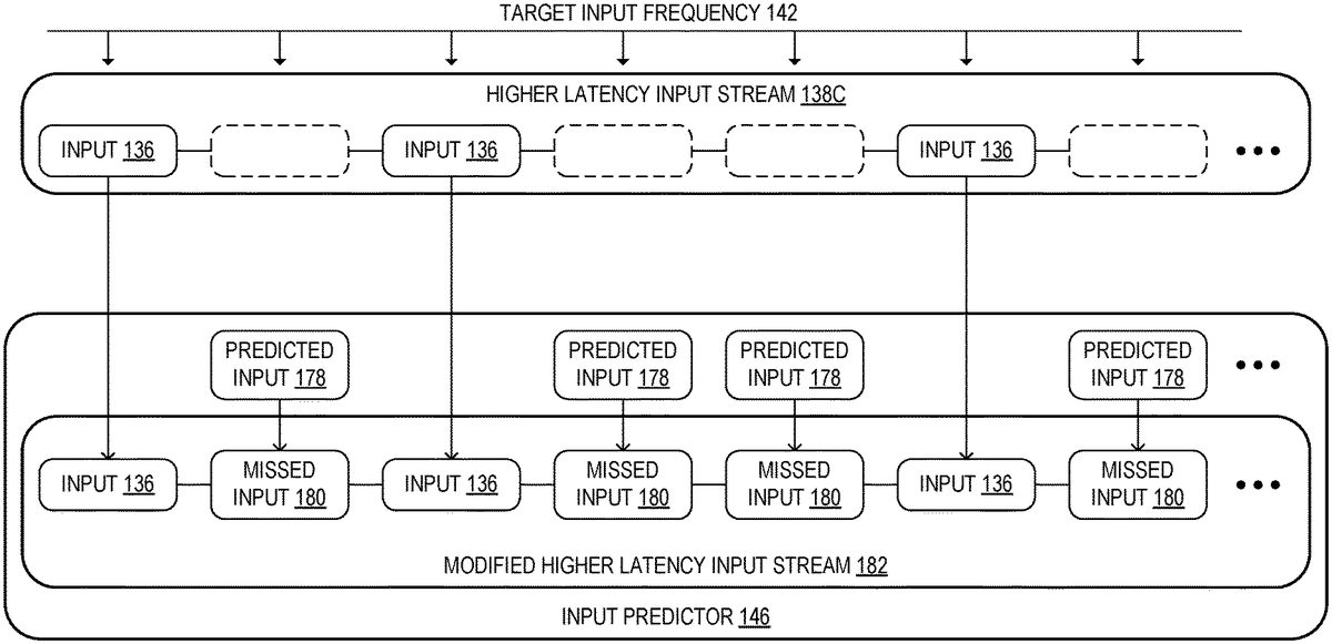
FIG. 4illustrates an example input predictor146generating predicted input to fill missed input in a higher latency input stream138C. As illustrated, the server computing device104expects input to be received from the client computing device102according to the target input frequency142. The input handler140of the server side streaming platform140implemented by the server computing device104may be configured to detect a missed input180in the higher latency input stream138C based on the target input frequency142. That is, if the server computing device104has not received an input from the client computing device for a threshold period of time after the expected point in time, the input handler140may determine that the client computing device has missed an input due to short-term high latency or instability of the network between that client computing device and the server computing device104. Upon detecting the missed input180, the input predictor146may be configured to determine a predicted input178as discussed above, and insert the predicted input178into the higher latency input stream138C to fill the missed input180.
The example illustrated inFIG. 4shows a sequence where only one or two inputs were missed in a row in the higher latency input stream138C. However, in some examples, due to instability of the network, the client computing device may potentially miss more consecutive inputs, such as, for example, five inputs, ten inputs, etc. In this example, the global latency manager and encoder152may be configured to detect whether the higher latency input stream138C has missed more consecutive inputs than a threshold missed input amount (which may be defined by the program developer), such as 5 inputs, 10 inputs, or 15 inputs, etc. If the higher latency input stream138C has missed more inputs than the threshold input amount, the global latency manager and encoder152may be configured to halt execution of the multiplayer online software program134until a next input has been received in the higher latency input stream138C. If the higher latency input stream138C has missed fewer inputs than the threshold input amount, the global latency manager and encoder152may be configured to instruct the input handler140to pull a new input from an input buffer168for that input stream and/or instruct the input predictor146to generate a new predicted input178to be inserted into the missed input slot in the higher latency input stream138C. The modified higher latency input stream182that includes actual input136and predicted input178may be sent to the remote execution device110and processed according to the methods described above.
It should be appreciated that the input predictor146may be implemented using any suitable combination of state-of-the-art and/or future machine learning (ML), artificial intelligence (AI), and/or natural language processing (NLP) techniques. For example, the machine learning model of the trained data180shown inFIG. 2may be trained to generate state machines that are utilized by the input predictor146to generate the predicted input178for a user of a particular client computing device102. In one example, the machine learning models may be trained based on a history of input data received from that particular client computing device102. In another example, the machine learning models may be trained based on a history of inputs received from a plurality of different users across different game sessions over time. Additionally, machine learning models of the trained data180may be shared between a plurality of different server computing devices104, which may be located in different geolocations, datacenters, etc. For example, the machine learning model of the trained data180shown inFIG. 2may have been trained using input data received by a plurality of different server computing devices104located in different datacenters, which may each receive input data from a plurality of different client computing devices.
Non-limiting examples of techniques that may be incorporated in an implementation include support vector machines, multi-layer neural networks, convolutional neural networks (e.g., including spatial convolutional networks for processing images and/or videos, temporal convolutional neural networks for processing audio signals and/or natural language sentences, and/or any other suitable convolutional neural networks configured to convolve and pool features across one or more temporal and/or spatial dimensions), recurrent neural networks (e.g., long short-term memory networks), associative memories (e.g., lookup tables, hash tables, Bloom Filters, Neural Turing Machine and/or Neural Random Access Memory), word embedding models (e.g., GloVe or Word2Vec), unsupervised spatial and/or clustering methods (e.g., nearest neighbor algorithms, topological data analysis, and/or k-means clustering), graphical models (e.g., (hidden) Markov models, Markov random fields, (hidden) conditional random fields, and/or AI knowledge bases), and/or natural language processing techniques (e.g., tokenization, stemming, constituency and/or dependency parsing, and/or intent recognition, segmental models, and/or super-segmental models (e.g., hidden dynamic models)).
In some examples, the methods and processes described herein may be implemented using one or more differentiable functions, wherein a gradient of the differentiable functions may be calculated and/or estimated with regard to inputs and/or outputs of the differentiable functions (e.g., with regard to training data, and/or with regard to an objective function). Such methods and processes may be at least partially determined by a set of trainable parameters. Accordingly, the trainable parameters for a particular method or process may be adjusted through any suitable training procedure, in order to continually improve functioning of the method or process.
Non-limiting examples of training procedures for adjusting trainable parameters include supervised training (e.g., using gradient descent or any other suitable optimization method), zero-shot, few-shot, unsupervised learning methods (e.g., classification based on classes derived from unsupervised clustering methods), reinforcement learning (e.g., deep Q learning based on feedback) and/or generative adversarial neural network training methods, belief propagation, RANSAC (random sample consensus), contextual bandit methods, maximum likelihood methods, and/or expectation maximization. In some examples, a plurality of methods, processes, and/or components of systems described herein may be trained simultaneously with regard to an objective function measuring performance of collective functioning of the plurality of components (e.g., with regard to reinforcement feedback and/or with regard to labelled training data). Simultaneously training the plurality of methods, processes, and/or components may improve such collective functioning. In some examples, one or more methods, processes, and/or components may be trained independently of other components (e.g., offline training on historical data).
FIG. 5shows a flowchart of a computer-implemented method500. The method500may be implemented by the server computing device ofFIG. 1. At502, the method500may include receiving a plurality of input streams from a respective plurality of client computing devices, each input stream including a plurality of inputs controlling actions of respective characters in a multiplayer online software program, such as, for example, moving, selecting, performing an action, etc. As described above with regard toFIG. 2, a streaming client108implemented by the client computing devices may send the plurality of inputs136in an input stream138to the server computing device104over the network106. Each client computing device102participating in the multiplayer online software program134may be configured to send input streams138to the server computing device104.
At504, the method500may include determining a latency of each of the input streams. As described above with reference toFIG. 2, a network predictor158of the client computing devices may be configured to profile the network latency and jitter of its respective network106. For example, the network predictor158may be configured to send packets to the server computing device104and measure the round-time trip of each packet. The network predictor158may analyze changes in round-time trips over time to determine short term and long term trends in the network latency and stability. In this manner, the network predictor158may generate network latency data160that includes predictions of network latency over long and short terms.
At506, the method500may include predicting a long-term latency for each of the plurality of input streams. As described above with reference toFIG. 2, the predicted long-term latency for each of the plurality of input streams138may be determined based on the network latency data162received from the network predictor of each client computing device102.
At508, the method500may include identifying a higher latency input stream and a lower latency input stream among the plurality of input streams. As described with reference toFIG. 2, the global latency manager and encoder of the server computing device104may be configured to compare the network latency data received from the client computing device102and identify higher and lower input latency streams. In one example, the global latency manager and encoder may be further configured to identify that a particular input stream is a high latency input stream based on detecting that there are missed inputs in that particular input stream according to a target input frequency.
At510, the method500may include inducing a higher latency in the lower latency input stream to narrow a difference in latency between the higher latency input stream and the lower latency input stream. In one example, the higher latency is induced in each other input stream other than a highest latency input stream of the plurality of input streams. The highest latency input stream may be determined based on the network latency data received from each client computing device.
At step510, the higher latency may be induced in the low latency input stream using different techniques. In one example, inducing the higher latency includes buffering inputs for each of the plurality of input streams. As described with reference toFIG. 3, each input136in each input stream138from the plurality of client computing devices102may be put into input buffers168when received by the server computing device104. Inputs136for each of the lower latency input streams138A and138B may be held in the input buffer168until a corresponding input from the higher latency input stream138C has been received by the input handler140of server computing device104. Once input136has been received from all of the client computing devices102, those inputs may be pulled from the input buffer168and sent to the remote execution device110which may then render corresponding output frames150based on those inputs.
In another example, inducing the higher latency may include buffering output frames for each of the plurality of output frame streams. As described with reference toFIG. 3, output frames150rendered by the remote execution device110may be held in respective output frame buffers170for each of the output frame streams154for the plurality of client computing devices102. The server computing device104may then pull output frames150from the respective output frame buffers170to be sent to the plurality of client computing devices102as controlled by the global latency manager and encoder152.
In another example, inducing the higher latency may include decreasing the controllable framerate to be less than a target framerate. As described with reference toFIG. 3, the global latency manager and encoder152may modify the controllable framerate150of the multiplayer online software program134based on the highest predicted long-term latency166. That is, as the perceived responsiveness (e.g. time elapsed between user input to displayed frame reflecting that input) of the multiplayer online software program134will already be reduced due to high network latency, the server computing device104may be configured to opportunistically decrease the controllable framerate150of the multiplayer online software program134.
At512, the method500may include increasing the induced higher latency in one or more lower latency input streams up to a highest predicted long-term latency of the plurality of input streams. Step512may include inducing increasing amounts of artificial latency into identified lower latency streams until each of the plurality of input and output streams of the client computing devices102have latencies within a threshold latency difference.
At514, the method500may include rendering output frames for a software program state of the multiplayer online software program for each of the plurality of client computing device at a controllable framerate. As described above with reference toFIG. 2, based on the streams of emulated inputs148, the remote execution device110may determine a current perspective of respective characters for each client computing device in a scene of the multiplayer online software program134, and may render views of those current perspectives as output frames150for each client computing device102.
At516, the method500may include sending the rendered output frames in a plurality of output frame streams to the respective plurality of client computing devices. As discussed at step512, the rendered output frames may be held in an output frame buffer in order to induce a higher latency on selected streams. The rendered output frames may be pulled from the output frame buffer and then sent to the associated client computing device to achieve a target induced latency in that stream.
At518, the method500may include causing each client computing device to interpolate intermediate frames based on one or more output frames in the output frame streams to achieve the target framerate. As described above with reference toFIG. 2, the frame interpolator176implemented by the client computing device may be configured to interpolate an intermediate frame174based on a rendered output frame preceding the intermediate frame174and/or a rendered output frame following the intermediate frame174. The frame interpolator176may be configured to interpolate intermediate frames174using interpolation techniques such as homography, time warping, image based rendering mesh warping, late stage reprojection techniques, neural network interpolation, and other suitable interpolation techniques. The output frames and the interpolated intermediate frames may be presented to the user via a display of the client computing device.
The above-described systems and methods may be utilized to maintain fairness in multiplayer sessions of online software programs by inducing latency into some player streams using a variety of techniques, to thereby enable each player to have a more similar game experience within the multiplayer session, despite each player having varying latencies in their respective network connections.
In some embodiments, the methods and processes described herein may be tied to a computing system of one or more computing devices. In particular, such methods and processes may be implemented as a computer-application program or service, an application-programming interface (API), a library, and/or other computer-program product.
FIG. 6schematically shows a non-limiting embodiment of a computing system In some embodiments, the methods and processes described herein may be tied to a computing system of one or more computing devices. In particular, such methods and processes may be implemented as a computer-application program or service, an application-programming interface (API), a library, and/or other computer-program product.
FIG. 6schematically shows a non-limiting embodiment of a computing system600that can enact one or more of the methods and processes described above. Computing system600is shown in simplified form. Computing system600may embody the client computing devices102and server computing device104described above and illustrated inFIGS. 1 and 2. Computing system600may take the form of one or more personal computers, server computers, tablet computers, home-entertainment computers, network computing devices, gaming devices, mobile computing devices, mobile communication devices (e.g., smart phone), and/or other computing devices, and wearable computing devices such as smart wristwatches and head mounted augmented reality devices.
Computing system600includes a logic processor602volatile memory604, and a non-volatile storage device606. Computing system600may optionally include a display subsystem608, input subsystem610, communication subsystem612, and/or other components not shown inFIG. 6.
Logic processor602includes one or more physical devices configured to execute instructions. For example, the logic processor may be configured to execute instructions that are part of one or more applications, programs, routines, libraries, objects, components, data structures, or other logical constructs. Such instructions may be implemented to perform a task, implement a data type, transform the state of one or more components, achieve a technical effect, or otherwise arrive at a desired result.
The logic processor may include one or more physical processors (hardware) configured to execute software instructions. Additionally or alternatively, the logic processor may include one or more hardware logic circuits or firmware devices configured to execute hardware-implemented logic or firmware instructions. Processors of the logic processor602may be single-core or multi-core, and the instructions executed thereon may be configured for sequential, parallel, and/or distributed processing. Individual components of the logic processor optionally may be distributed among two or more separate devices, which may be remotely located and/or configured for coordinated processing. Aspects of the logic processor may be virtualized and executed by remotely accessible, networked computing devices configured in a cloud-computing configuration. In such a case, these virtualized aspects are run on different physical logic processors of various different machines, it will be understood.
Non-volatile storage device606includes one or more physical devices configured to hold instructions executable by the logic processors to implement the methods and processes described herein. When such methods and processes are implemented, the state of non-volatile storage device604may be transformed—e.g., to hold different data.
Non-volatile storage device606may include physical devices that are removable and/or built-in. Non-volatile storage device604may include optical memory (e.g., CD, DVD, HD-DVD, Blu-Ray Disc, etc.), semiconductor memory (e.g., ROM, EPROM, EEPROM, FLASH memory, etc.), and/or magnetic memory (e.g., hard-disk drive, floppy-disk drive, tape drive, MRAM, etc.), or other mass storage device technology. Non-volatile storage device606may include nonvolatile, dynamic, static, read/write, read-only, sequential-access, location-addressable, file-addressable, and/or content-addressable devices. It will be appreciated that non-volatile storage device606is configured to hold instructions even when power is cut to the non-volatile storage device606.
Volatile memory604may include physical devices that include random access memory. Volatile memory604is typically utilized by logic processor602to temporarily store information during processing of software instructions. It will be appreciated that volatile memory604typically does not continue to store instructions when power is cut to the volatile memory604.
Aspects of logic processor602, volatile memory604, and non-volatile storage device606may be integrated together into one or more hardware-logic components. Such hardware-logic components may include field-programmable gate arrays (FPGAs), program- and application-specific integrated circuits (PASIC/ASICs), program- and application-specific standard products (PSSP/ASSPs), system-on-a-chip (SOC), and complex programmable logic devices (CPLDs), for example.
The terms “module,” “program,” and “engine” may be used to describe an aspect of computing system600typically implemented in software by a processor to perform a particular function using portions of volatile memory, which function involves transformative processing that specially configures the processor to perform the function. Thus, a module, program, or engine may be instantiated via logic processor602executing instructions held by non-volatile storage device606, using portions of volatile memory604. It will be understood that different modules, programs, and/or engines may be instantiated from the same application, service, code block, object, library, routine, API, function, etc. Likewise, the same module, program, and/or engine may be instantiated by different applications, services, code blocks, objects, routines, APIs, functions, etc. The terms “module,” “program,” and “engine” may encompass individual or groups of executable files, data files, libraries, drivers, scripts, database records, etc.
When included, display subsystem608may be used to present a visual representation of data held by non-volatile storage device606. The visual representation may take the form of a graphical user interface (GUI). As the herein described methods and processes change the data held by the non-volatile storage device, and thus transform the state of the non-volatile storage device, the state of display subsystem608may likewise be transformed to visually represent changes in the underlying data. Display subsystem608may include one or more display devices utilizing virtually any type of technology. Such display devices may be combined with logic processor602, volatile memory604, and/or non-volatile storage device606in a shared enclosure, or such display devices may be peripheral display devices.
When included, input subsystem610may comprise or interface with one or more user-input devices such as a keyboard, mouse, touch screen, or game controller. In some embodiments, the input subsystem may comprise or interface with selected natural user input (NUI) componentry. Such componentry may be integrated or peripheral, and the transduction and/or processing of input actions may be handled on- or off-board. Example NUI componentry may include a microphone for speech and/or voice recognition; an infrared, color, stereoscopic, and/or depth camera for machine vision and/or gesture recognition; a head tracker, eye tracker, accelerometer, and/or gyroscope for motion detection and/or intent recognition; as well as electric-field sensing componentry for assessing brain activity; and/or any other suitable sensor.
When included, communication subsystem612may be configured to communicatively couple various computing devices described herein with each other, and with other devices. Communication subsystem612may include wired and/or wireless communication devices compatible with one or more different communication protocols. As non-limiting examples, the communication subsystem may be configured for communication via a wireless telephone network, or a wired or wireless local- or wide-area network, such as a HDMI over Wi-Fi connection. In some embodiments, the communication subsystem may allow computing system600to send and/or receive messages to and/or from other devices via a network such as the Internet.
The following paragraphs provide additional support for the claims of the subject application. One aspect provides a server computing device, comprising a processor configured to receive a plurality of input streams from a respective plurality of client computing devices. Each input stream includes a plurality of inputs controlling actions of respective characters in a multiplayer online software program. The processor is further configured to determine a latency of each of the input streams, identify a higher latency input stream and a lower latency input stream among the plurality of input streams, and induce a higher latency in the lower latency input stream to narrow a difference in latency between the higher latency input stream and the lower latency input stream. In this aspect, additionally or alternatively, the higher latency may be induced in each other input stream other than a highest latency input stream of the plurality of input streams. In this aspect, additionally or alternatively, the processor may be further configured to predict a long-term latency for each of the plurality of input streams, and increase the induced higher latency in one or more lower latency input streams up to a highest predicted long-term latency of the plurality of input streams. In this aspect, additionally or alternatively, the processor may be configured to induce the higher latency by buffering inputs for each of the plurality of input streams. In this aspect, additionally or alternatively, the processor may be configured to render output frames for a software program state of the multiplayer online software program for each of the plurality of client computing device at a controllable framerate, and send the rendered output frames in a plurality of output frame streams to the respective plurality of client computing devices. In this aspect, additionally or alternatively, the processor may be further configured to induce the higher latency by buffering output frames for each of the plurality of output frame streams. In this aspect, additionally or alternatively, the processor may be further configured to induce the higher latency by decreasing the controllable framerate to be less than a target framerate. In this aspect, additionally or alternatively, the processor may be configured to cause each client computing device to interpolate intermediate frames based on one or more output frames in the output frame streams to achieve the target framerate. In this aspect, additionally or alternatively, the processor may be configured to determine the latency of each of the input streams based on detecting whether inputs were received from each of the input streams at a target input frequency. In this aspect, additionally or alternatively, the processor may be configured to detect a missed input in the higher latency input stream based on the target input frequency, and insert a predicted input into the higher latency input stream to fill the missed input. In this aspect, additionally or alternatively, the predicted input may be determined based on trained input data including a history of inputs in that input stream.
Another aspect provides a method comprising, at a server computing device including a processor, receiving a plurality of input streams from a respective plurality of client computing devices. Each input stream includes a plurality of inputs controlling actions of respective characters in a multiplayer online software program. The method further comprises determining a latency of each of the input streams, identifying a higher latency input stream and a lower latency input stream among the plurality of input streams, and inducing a higher latency in the lower latency input stream to narrow a difference in latency between the higher latency input stream and the lower latency input stream. In this aspect, additionally or alternatively, the higher latency may be induced in each other input stream other than a highest latency input stream of the plurality of input streams. In this aspect, additionally or alternatively, the method may further comprise predicting a long-term latency for each of the plurality of input streams, and increasing the induced higher latency in one or more lower latency input streams up to a highest predicted long-term latency of the plurality of input streams. In this aspect, additionally or alternatively, inducing the higher latency may include buffering inputs for each of the plurality of input streams. In this aspect, additionally or alternatively, the method may further comprise rendering output frames for a software program state of the multiplayer online software program for each of the plurality of client computing device at a controllable framerate, and sending the rendered output frames in a plurality of output frame streams to the respective plurality of client computing devices. In this aspect, additionally or alternatively, inducing the higher latency may include buffering output frames for each of the plurality of output frame streams. In this aspect, additionally or alternatively, inducing the higher latency may include decreasing the controllable framerate to be less than a target framerate. In this aspect, additionally or alternatively, the method may further comprise causing each client computing device to interpolate intermediate frames based on one or more output frames in the output frame streams to achieve the target framerate.
Another aspect provides a server computing device, comprising a processor configured to receive a plurality of input streams from a respective plurality of client computing devices. Each input stream includes a plurality of inputs controlling actions of respective characters in a multiplayer online software program. The processor is further configured to determine a latency of each of the input streams including a highest predicted long-term latency, identify a higher latency input stream and a lower latency input stream among the plurality of input streams; induce a higher latency in the lower latency input stream up to the highest predicted long-term latency, and detect one or more missed inputs in the higher latency input stream based on a target input frequency. If the one or more missed inputs is greater than a threshold amount of inputs, the processor is configured to halt execution of the multiplayer online software program. If the one or more missed inputs is lower than the threshold amount of inputs, the processor is configured to insert a predicted input into the higher latency input stream to fill the missed input.
It will be understood that the configurations and/or approaches described herein are exemplary in nature, and that these specific embodiments or examples are not to be considered in a limiting sense, because numerous variations are possible. The specific routines or methods described herein may represent one or more of any number of processing strategies. As such, various acts illustrated and/or described may be performed in the sequence illustrated and/or described, in other sequences, in parallel, or omitted. Likewise, the order of the above-described processes may be changed.
The subject matter of the present disclosure includes all novel and non-obvious combinations and sub-combinations of the various processes, systems and configurations, and other features, functions, acts, and/or properties disclosed herein, as well as any and all equivalents thereof.
Claims
- A server computing device, comprising a processor configured to: receive a plurality of input streams from a respective plurality of client computing devices, each input stream including a plurality of inputs controlling actions of respective characters in a multiplayer game session of a multiplayer online software program;determine a latency of each of the input streams based at least on detecting whether inputs were received from each of the plurality of input streams at a target input frequency;identify a higher latency input stream and a lower latency input stream among the plurality of input streams, wherein missed inputs not received at the target input frequency are used to identify the higher latency input stream;and induce a higher latency in the lower latency input stream to narrow a difference in latency between the higher latency input stream and the lower latency input stream, to thereby accommodate the higher latency input stream and the lower latency input stream in the multiplayer game session.
- The server computing device of claim 1 , wherein the higher latency is induced in each other input stream other than a highest latency input stream of the plurality of input streams.
- The server computing device of claim 1 , wherein the processor is further configured to: predict a long-term latency for each of the plurality of input streams;and increase the induced higher latency in one or more lower latency input streams up to a highest predicted long-term latency of the plurality of input streams.
- The server computing device of claim 1 , wherein the processor is configured to induce the higher latency by buffering inputs for each of the plurality of input streams.
- The server computing device of claim 1 , wherein the processor is configured to: render output frames for a software program state of the multiplayer online software program for each of the plurality of client computing device at a controllable framerate;and send the rendered output frames in a plurality of output frame streams to the respective plurality of client computing devices.
- The server computing device of claim 5 , wherein the processor is further configured to induce the higher latency by buffering output frames for each of the plurality of output frame streams.
- The server computing device of claim 5 , wherein the processor is further configured to induce the higher latency by decreasing the controllable framerate to be less than a target framerate.
- The server computing device of claim 7 , wherein the processor is configured to cause each client computing device to interpolate intermediate frames based on one or more output frames in the output frame streams to achieve the target framerate.
- The server computing device of claim 1 , wherein the processor is configured to: detect a missed input in the higher latency input stream based on the target input frequency;and insert a predicted input into the higher latency input stream to fill the missed input.
- The server computing device of claim 9 , wherein the predicted input is determined based on trained input data including a history of inputs in that input stream.
- A method comprising: at a server computing device including a processor, receiving a plurality of input streams from a respective plurality of client computing devices, each input stream including a plurality of inputs controlling actions of respective characters in a multiplayer game session of a multiplayer online software program;determining a latency of each of the input streams based at least on detecting whether inputs were received from each of the plurality of input streams at a target input frequency;identifying a higher latency input stream and a lower latency input stream among the plurality of input streams, wherein missed inputs not received at the target input frequency are used to identify the higher latency input stream;and inducing a higher latency in the lower latency input stream to narrow a difference in latency between the higher latency input stream and the lower latency input stream to thereby accommodate the higher latency input stream and the lower latency input stream in the multiplayer game session.
- The method of claim 11 , wherein the higher latency is induced in each other input stream other than a highest latency input stream of the plurality of input streams.
- The method of claim 11 , further comprising: rendering output frames for a software program state of the multiplayer online software program for each of the plurality of client computing device at a controllable framerate;and sending the rendered output frames in a plurality of output frame streams to the respective plurality of client computing devices.
- The method of claim 13 , wherein inducing the higher latency includes buffering output frames for each of the plurality of output frame streams.
- The method of claim 13 , wherein inducing the higher latency includes decreasing the controllable framerate to be less than a target framerate.
- The method of claim 15 , further comprising causing each client computing device to interpolate intermediate frames based on one or more output frames in the output frame streams to achieve the target framerate.
- A server computing device, comprising a processor configured to: receive a plurality of input streams from a respective plurality of client computing devices, each input stream including a plurality of inputs controlling actions of respective characters in a multiplayer online software program;determine a latency of each of the input streams including a highest predicted long-term latency;identify a higher latency input stream and a lower latency input stream among the plurality of input streams;induce a higher latency in the lower latency input stream up to the highest predicted long-term latency;detect one or more missed inputs in the higher latency input stream based on a target input frequency;if the one or more missed inputs is greater than a threshold amount of inputs, halt execution of the multiplayer online software program;and if the one or more missed inputs is lower than the threshold amount of inputs, insert a predicted input into the higher latency input stream to fill the missed input.
- The server computing device of claim 17 , wherein the predicted input is determined based on trained input data including a history of inputs in that input stream.
- The server computing device of claim 17 , wherein the processor is configured to: render output frames for a software program state of the multiplayer online software program for each of the plurality of client computing device at a controllable framerate;and send the rendered output frames in a plurality of output frame streams to the respective plurality of client computing devices.
Disclaimer: Data collected from the USPTO and may be malformed, incomplete, and/or otherwise inaccurate.