U.S. Patent No. 10,799,802: Game System
Issued October 13, 2020 to Lego AS
Filed: April 7, 2016 (Claiming priority to April 8, 2015)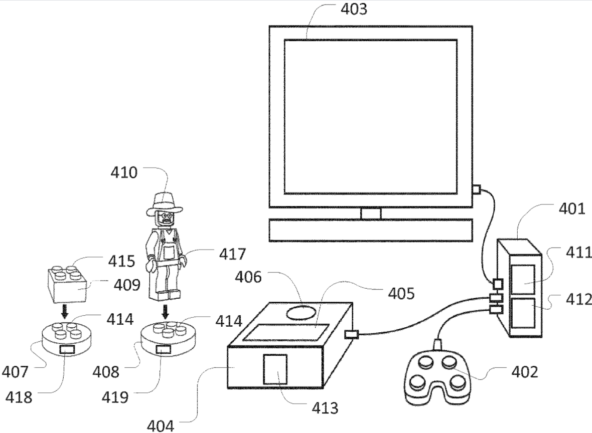
Overview:
U.S. Patent No. 10,799,802 (the ‘802 patent) relates to a game system that allows a user to engage in digital gameplay via physical manipulation of a physical toy. The ‘802 patent details a game system with a detection device for detecting a physical toy. The physical toy is made out of one or more construction pieces and two or more identification elements and the construction elements of the toy can be interchangeably connected. The toy can be detected by the detection device when it is a coherent structure and when two or more identification elements are positioned within the detection area. The user can then selectively position the toy with a user-selected subset of the two or more identification elements and, in response to the detected identification elements, the gaming system controls digital gameplay.
LEGO has already expanded into the digital gaming environment with a good deal of success, with beloved games like LEGO Star Wars. The ‘802 could combine digital games and physical toys for interesting control schemes and cross over between toys and video games.
Abstract:
A game system, comprising: a data processing system configured to execute program instructions allowing a user to engage in digital game play; a physical toy; and a detection device configured to detect a presence of the toy within a detection area of the detection device; wherein the toy comprises two or more identification elements each detectable by the detection device when the identification element is positioned within the detection area, wherein the toy is configured to allow a user to selectively position the toy with a user-selected subset of one or more of said identification elements within the detection area; and wherein the data processing system is configured to control said digital game play responsive to the detected subset of identification elements.
Illustrative Claim:
- A game system, comprising: a data processing system configured to execute program instructions allowing a user to engage in digital game play; a physical toy; and a detection device configured to detect a presence of the toy within a detection area of the detection device; wherein the physical toy comprises one or more construction elements and two or more identification elements, said one or more construction elements being interchangeably connectable to said two or more identification elements; wherein the two or more identification elements are each detectable by the detection device when each of said two or more identification elements is positioned within the detection area; wherein the physical toy is a coherent structure wherein at least one of the two or more identification elements are physically interconnected with the one or more construction elements; wherein the physical toy is configured to allow a user to selectively position the physical toy with only a user-selected subset of the two or more identification elements within the detection area; and wherein the data processing system is configured to control said digital game play responsive to the detected subset of identification elements.
Illustrative Figure
Abstract
A game system, comprising: a data processing system configured to execute program instructions allowing a user to engage in digital game play; a physical toy; and a detection device configured to detect a presence of the toy within a detection area of the detection device; wherein the toy comprises two or more identification elements each detectable by the detection device when the identification element is positioned within the detection area, wherein the toy is configured to allow a user to selectively position the toy with a user-selected subset of one or more of said identification elements within the detection area; and wherein the data processing system is configured to control said digital game play responsive to the detected subset of identification elements.
Description
DETAILED DESCRIPTION Various aspects and embodiments of game systems and toy construction systems disclosed herein will now be described with reference to toy construction elements in the form of bricks. However, the invention may be applied to other forms of construction elements for use in toy construction sets. InFIG. 1is shown a toy construction element with coupling studs on its top surface and a cavity extending into the brick from the bottom. The cavity has a central tube, and coupling studs on another brick can be received in the cavity in a frictional engagement as disclosed in U.S. Pat. No. 3,005,282.FIGS. 2 and 3show other such prior art construction elements. The construction elements shown in the remaining figures have this known type of connectors in the form of cooperating studs and cavities. However, other types of connectors may also be used in addition to or instead of the studs and cavities. The coupling studs are arranged in a square planar grid, i.e. defining orthogonal directions along which sequences of coupling studs are arranged. The distance between neighbouring coupling studs is uniform and equal in both directions. This or similar arrangements of connectors at coupling locations defining a regular planar grid allow the toy construction elements to be interconnected in a discrete number of positions and orientations relative two each other, in particular at right angles with respect to each other. FIG. 4shows an embodiment of a game system. The system comprises a computer401, an input device402connected to the computer, a display403connected to the computer, a reader404connected to the computer, a number of identification elements407,408, and a number of toy construction elements409,410. The computer401may be a personal computer, a desktop computer, a laptop computer, a handheld computer such as a tablet computer, a smartphone or the like, a game console, a ...
DETAILED DESCRIPTION
Various aspects and embodiments of game systems and toy construction systems disclosed herein will now be described with reference to toy construction elements in the form of bricks. However, the invention may be applied to other forms of construction elements for use in toy construction sets.
InFIG. 1is shown a toy construction element with coupling studs on its top surface and a cavity extending into the brick from the bottom. The cavity has a central tube, and coupling studs on another brick can be received in the cavity in a frictional engagement as disclosed in U.S. Pat. No. 3,005,282.FIGS. 2 and 3show other such prior art construction elements. The construction elements shown in the remaining figures have this known type of connectors in the form of cooperating studs and cavities. However, other types of connectors may also be used in addition to or instead of the studs and cavities. The coupling studs are arranged in a square planar grid, i.e. defining orthogonal directions along which sequences of coupling studs are arranged. The distance between neighbouring coupling studs is uniform and equal in both directions. This or similar arrangements of connectors at coupling locations defining a regular planar grid allow the toy construction elements to be interconnected in a discrete number of positions and orientations relative two each other, in particular at right angles with respect to each other.
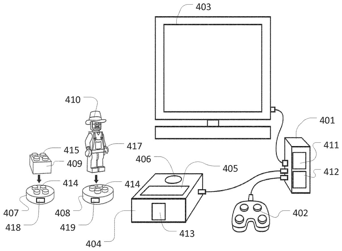
FIG. 4shows an embodiment of a game system. The system comprises a computer401, an input device402connected to the computer, a display403connected to the computer, a reader404connected to the computer, a number of identification elements407,408, and a number of toy construction elements409,410.
The computer401may be a personal computer, a desktop computer, a laptop computer, a handheld computer such as a tablet computer, a smartphone or the like, a game console, a handheld entertainment device, or any other suitably programmable computer. The computer401comprises a processor411such as a Central Processing Unit (CPU) and one or more storage devices412such as a memory, a hard disk, and/or the like.
The display403is operatively coupled to the computer401and the computer401is configured to present a graphical representation of a virtual environment on the display403. Though illustrated as separate components inFIG. 4, it will be appreciated that the display may be integrated in the housing of the computer.
The input device402is operatively coupled to the computer401and is configured to receive user inputs. For example, the input device may comprise a keyboard, a mouse, or other pointing device, and/or the like. In some embodiments, the system comprises more than one input device. In some embodiments an input device may be integrated in the computer and/or the display, e.g. in the form of a touch screen. It will be appreciated that the system may comprise further peripheral computer devices operatively coupled to, such as integrated into, the computer.
The reader404is operable to detect one or more identification elements. To this end, the reader defines two detection areas405and406respectively, and the reader is operable to detect an identification element when positioned in one of the detection areas. The reader comprises one or more RFID circuits413and corresponding one or more antennas operable to detect an identification element placed on one of the detection areas. Alternatively, the reader may employ a different detection and data communication technology. In some embodiments the reader may be integrated in the computer and/or the display and/or the input device402.
The identification elements407and408have the form of a base plate with connectors414on its top surface. The connectors414are compatible with the known construction elements described in connection withFIGS. 1-3. The game system further comprises one or more toy construction elements409and410, e.g. of the type described in connection withFIGS. 1-3. WhileFIG. 4shows two construction elements, it will be appreciated that a game system may include any number of construction elements. One of the construction elements409has the shape of a building block as described in connection withFIG. 1, and another construction element410has the shape of a human figure. Both construction elements have connectors—in this example cavities—for attachment to the connectors of the identification elements. Both construction elements have additional connectors415,417allowing a user to connect further construction elements so as to construct a toy construction model comprising multiple construction elements. Each of the identification elements comprises an RFID circuit418,419, respectively, operable to receive and store information. If another detection technology is used, the identification element may comprise a corresponding detection circuit or device. In particular, the stored information may identify a virtual object associated with the identification toy construction element. In some embodiments, one or more of the identification elements included in a game system may be manufactured with pre-stored information indicative of a predetermined virtual object. Alternatively or additionally, one or more identification elements may be manufactured without pre-stored information about any specific virtual object. In some embodiments, the game system may comprise one or more toy identification elements where the pre-stored information is read-only, i.e. where the identification element is associated to a fixed virtual object. For example, a game set may comprise one or more read-only identification elements and additionally one or more rewritable identification elements. The read-only and rewritable identification elements may be visually distinguishable from each other; for example, they may have a different size, shape, color, design, etc. The read-only identification elements may be associated with virtual characters of the game, while the game system may allow the user to associate the rewritable identification elements with inanimate virtual objects.
The display403, the reader404and the input device402may be operationally coupled to the computer in a variety of ways. For example one or more of the above devices may be coupled to the computer via a suitable wired or wireless input interface of the computer401, e.g. via a serial or parallel port of the computer such as a USB port, via Bluetooth, Wifi or another suitable wireless communications interface. Alternative, one or all of the devices may be integrated into the computer. For example, the computer may comprise an integrated display and/or input device and/or an integrated detection device. In particular, many tablet computers and smartphones comprise an integrated touch screen operable as a display and input device.
The computer401has stored thereon a program, e.g. an App or other software application, adapted to simulate a virtual environment and to create and control virtual objects as described herein.
It will be appreciated that, in some embodiments, the computer401may be communicatively connected to a host system, e.g. via the Internet or another suitable computer network. At least a part of the processing described herein may then be performed by the host system. For example, in some embodiments, a host system may generate and simulate a virtual environment, such as a virtual world which may be accessible by multiple users from respective client computers. A user may use a client computer executing a suitable program to detect identification elements and cause the client or the host system to create a corresponding virtual object. The host system may then add the virtual object to the virtual world and control the virtual object within the virtual world.
The user may construct respective toy construction models on top of each of the identification elements which each have the form of a base plate. Alternatively, the identification elements may be incorporated in a toy construction model in a different manner. In use, when the user places an identification element, e.g. with a toy construction model connected to it, on the detection area405of the reader, the reader detects the presence of the identification element and accesses the information stored in it, if any. The accessed information comprises information about which virtual object the identification element is associated with or the accessed information allows the computer to otherwise identify the associated virtual object. In some embodiments, the information includes additional information, e.g. indicative of an input to a sensor, as will be described in greater detail below. Responsive to the detection of the identification element in detection area405, the computer thus creates or otherwise presents a representation of the associated virtual object in a virtual environment. In particular, the computer may create a representation of the associated virtual object on the display and/or allow the user to control or otherwise use or engage the created virtual object in the virtual environment.
When the user positions an identification element, e.g. with a toy construction model connected to it, within the detection area406of the reader, the reader detects the presence of the identification element and allows the user to store information about a virtual object on the identification element. Hence, when the user subsequently positions the identification element on the detection area405, the computer creates or enables the corresponding virtual object as described above. Generally, the detection area406may be shaped and/or sized so as to allow a user to only position a single identification element on the detection area406so as to allow writing to only a single identification element at a time. For example, the detection area may be formed as a recess having a size and shape corresponding the shape and size of the identification elements, i.e. such that a single identification element may be placed within the recess. To this end the detection area406may be recessed into a top surface of the housing of the detection device. Alternatively or additionally, an elevated rim may be formed around the detection area. It will be appreciated that detection area405may be shaped and sized so as to allow detection of more than one identification element at a time.
In some embodiments, detection area406is selectively used for reading and writing from/to an identification element, but such that upon placement of an identification element on detection area406, the data processor either only reads data from the identification element or writes data to the identification element. For example, the identification element may comprise multiple memory areas and/r have stored thereon multiple types/categories of information. Upon placement of an identification element within detection area405, all memory areas and/or data categories may be read but not altered. Upon placement of an identification element within detection area406some memory areas and/or data categories may be read but not altered, while other memory areas may be written to but not read from.
FIG. 5shows another embodiment of a game system. The system ofFIG. 5is similar to the system ofFIG. 4and comprises a computer401, an input device402connected to the computer, a display403connected to the computer, a reader404connected to the computer, a number of identification elements407,408, and a number of toy construction elements409,410, all as described in connection withFIG. 4. The system ofFIG. 5differs from the one ofFIG. 4in that the reader comprises three detection areas: A writable detection area406as described in connection withFIG. 4and two read-only detection areas405a,beach as the detection area405ofFIG. 4. The provision of two read-only detection areas405a,bfacilitates two-player games or other types of games where two classes of virtual objects are to be distinguished, e.g. objects belonging to two different players, to two different teams, etc. The physical separation of the two detection areas thus provides an easy-to-use mechanism for a user to define members of the two classes of virtual objects by simply placing the corresponding identification element on a selected one of the detection areas405a,b, where each detection area is associated with one of the classes. It will be appreciated that other embodiments may comprise additional detection areas, e.g. to define more than two classes of objects. In some embodiments, the respective detection areas405a,bare associated with different regions of a game space or another virtual environment.
FIG. 6illustrates an example of a use of an embodiment of a game system, e.g. the game system ofFIG. 4. In particular, the system ofFIG. 6comprises a computer401, an input device402connected to the computer, a display403connected to the computer, a reader404connected to the computer, a number of identification elements407,408, and a number of toy construction elements409,410, all as described in connection withFIG. 4.
In this example one of the identification elements408has stored thereon information about a virtual character and the game system comprises a physical toyFIG. 410resembling the virtual character. In an initial step, the user is instructed to assemble the toyFIG. 410with the identification element408. The computer401is configured to execute a video game program which comprises a corresponding virtual character that is controllable by a user via input device402. When the user positions the identification element408on the detection area405of the reader, the computer detects the identification element, identifies the associated virtual character and causes the associated virtual character to appear in the video game. During game play where the user controls the virtual character, a game event may occur that unlocks certain equipment, in this example a tractor, which the virtual character may use during subsequent game play.
Responsive to the game event, the computer may provide an indication to the user that the user may obtain a virtual tractor (or another virtual object such as other equipment which the virtual character may utilise or otherwise engage in the game play).FIG. 5Ashows the game system with the identification element408and attached toyFIG. 410positioned within detection area405of the reader404and with an indication620of the unlocked virtual object displayed on display403. Optionally, the computer may further provide building instructions for instructing the user how to construct a corresponding toy construction model resembling a tractor from the toy construction elements409. The user may thus construct a toy construction model and attach it to another identification element407of the game system. When the user places the identification element407with the newly constructed model on the detection area406of the reader404, the computer stores an identifier and/or other information indicative of the newly unlocked virtual object on the identification element407. In some embodiments, this process may require the identification element408associated with the original virtual character to still be positioned in the detection area405. The storing of the identification of the new virtual object on an identification element does not require the system to access the currently stored information on the identification element; hence detection area406may be operated as a write-only area.
Once the information about the new virtual object is successfully stored on identification element407, the user may remove the identification element from the detection area406. When the user subsequently places the identification element407on the detection area405, e.g. together with the identification element408, as illustrated inFIG. 5B, the computer401controls the video game so as to allow the user to control the virtual character associated with identification element408and to allow the virtual character to use or otherwise engage a virtual object associated with the identification element407. For example, the virtual character may now be able to drive a virtual tractor. It will be appreciated that subsequently, the user may create and unlock further virtual objects in a manner similar to the one described above, and the virtual character may then use further equipment or other virtual objects. The further virtual objects may be associated with additional identification elements or the system may create a new association of the identification element407with a new virtual object, e.g. a larger tractor or different type of machine. Such new association may then replace the previous association.
It will also be appreciated that, in some embodiments, the data processing system may use detection area406for reading data from identification elements, e.g. in a manner similar to detection area406. For example, upon detection of a placement of an identification element within detection area406, the data processing system may selectively operate the detection area406either as a read-only area or as a write-only area until the identification element is again removed from detection area406. Upon subsequent placement of an identification element, the processing system may again determine/select, e.g. responsive to user input, game events and/or other conditions, whether to operate detection area406as a write-only or as a read-only area until the identification element is again removed from the detection area. It will be appreciated that the selective operation of detection area406in a read-only or in a write-only mode may also be implemented in an embodiment with more than two detection areas, e.g. in the embodiment described in connection withFIG. 5.
FIG. 7illustrates another example of the operation of an embodiment of a game system, e.g. the game system of one ofFIGS. 4-6. In particular,FIG. 7shows a reader404. Though not explicitly shown inFIG. 7, the reader404may be connected to a computer as described in connection with one or more of the previous figures. The reader404is of the type described in connection withFIG. 5, i.e. a reader for reading RFID identification elements where the reader comprises three detection areas: A writable detection area406as described in connection withFIG. 4and two read-only detection areas405a,b.FIG. 7further shows a first toy409comprising a first identification element positioned on detection area405b. In this example, the first toy resembles tractor attached to an identification element407comprising an RFID circuit as described in connection with the previous figures. When the tractor is positioned on the detection area405b, the computer may control the video game so as to allow the user to control a virtual character to use or otherwise engage with a virtual tractor. To this end, information associating the identification element407with a virtual tractor may have been pre-stored on the identification element during manufacturing of the system, or the information may have been stored by the user, e.g. as described in connection withFIG. 1 or 6.
FIG. 7shows a second toy709which comprises a second RFID identification element707and which is also positioned on detection area405b, along with and next to the first toy. In this example, the second toy resembles an engine block which is attached to an identification element707as described in connection with the previous figures. When the tractor409is positioned on the detection area405balong with the engine block709, the computer may control the video game so as to allow the user to control a virtual character to use or otherwise engage with an enhanced virtual tractor, e.g. a tractor being capable of driving faster and/or pulling heavier equipment than the tractor without the enhancement. To this end, information associating the identification element707with an enhancement to a virtual tractor may have been pre-stored on the identification element during manufacturing of the system, or the information may have been stored by the user, e.g. as described in connection withFIGS. 4-6. Hence, the virtual tractor corresponding to toy409may possess different attributes depending on whether toy409is positioned within a detection area of the reader alone (or together with other items not configured to modify the tractor) or together with the engine block toy709. When the tractor409is placed within the detection area405b, the corresponding virtual tractor may also be represented in a different way on the display of the computer, depending on whether it is placed on the reading area with or without the engine block. For example, the virtual tractor may be displayed with a smaller or with a larger engine. It will be appreciated that the engine block709may also be configured to affect other virtual toys, e.g. a virtual car, a virtual air plane, depending on whether the engine block is positioned on a detection area along with a toy associated with a virtual car, a virtual air plane, etc. Moreover, it will be appreciated that the engine block may be configured not to affect certain other virtual items, such as a virtual character, a virtual tree, etc. even though the engine block is placed on the detection area with a physical toy associated with a virtual character, a virtual tree, etc. Hence, a physical toy may be associated with an accessory or enhancement to a virtual object that itself is associated with another physical toy. When the physical toy and the other physical toy are placed within the detection area of the reader, the virtual object associated with the other physical toy may be represented as having the accessory or enhancement. It will be appreciated that in some embodiments, the accessory toy has to be positioned within the same detection area as another toy for it to affect the virtual object associated with said other toy. In other embodiments, the accessory toy has to be positioned within a different detection area than another toy for it to affect the virtual object associated with said other toy. Finally, in yet alternative embodiments, the accessory toy may affect a virtual object associated with another toy regardless of whether the physical toy and the other toy are positioned in the same or in different detection areas. The particular enhancement provided may depend on the placement in the same or in different detection areas.
FIG. 8illustrates an example of an RFID reader404. Though not explicitly shown inFIG. 8, the reader404which may be connected to a computer via a wired or wireless connection as described in connection with one or more of the previous figures. The reader404is of the type described in connection withFIG. 5, i.e. a reader comprising three detection areas: A writable detection area406as described in connection withFIG. 4and two read-only detection areas405a,b.
The detection areas are all located on the top surface of a housing of the reader404, but spaced apart from each other. In the present example, the detection areas405aand405bare L-shaped and allow at least three identification elements to be positioned within each of the detection areas405aand405b, e.g. one identification element in each leg of the L and a third identification element in the area where the legs meet. The detection area406is shaped and sized so as to allow only a single identification element to be positioned within detection area406at a time. The top surface of the reader406comprises two sets of connectors816a,b. In the present example, the connectors are protrusions arranged in a regular two-dimensional grid and configured to frictionally engage corresponding cavities on a bottom surface of another toy construction element. The connectors are arranged adjacent the respective detection areas405aand405b. So as to allow toy construction elements of the type described herein to be connected to the reader404. Hence, the user may add decorative parts to the reader or the user may attach toy construction models including identification elements to the reader, e.g. as described in connection withFIG. 9below.
FIG. 9shows the reader404ofFIG. 8with a toy construction model909attached to the connectors816anext to detection area405aThe toy construction model909comprises a first part921and a second part922connected to the first part via a hinge923, The first and second parts may be formed as a single component or from multiple toy construction elements. The second part comprises an identification element407, e.g. an RFID identification element as described in connection withFIGS. 4-6. Hence, when the first part1is fixedly attached to the top surface of the reader404, the second part922including identification element407may be pivoted around hinge923such that the identification element407may either be moved into an activated state close to detection area405aor into an inactivated state further removed from the detection area405a. Moreover, the identification element407comprises a coil antenna defining an axis projecting axially out of a bottom surface of the disc-shaped identification element. Similarly, detection area405ahas a reader antenna associated with it which also defines an axial direction projecting normally out of detection area405a. In the activated state, the axes of the identification element407and of the detection area405aare aligned with each other, while they are misaligned at the inactivated state. The reader is configured such that it can only detect the presence of identification element407within the detection area405a, when the second part922is pivoted such that the identification element407is in the activated state. The computer connected to the reader404may thus be configured to control game play responsive to whether the detection element407is currently in the activated or in the deactivated state. Consequently, the user may conveniently activate/deactivate a function of the game system by lowering or raising the second part of the toy onto or away from the detection surface defining the detection area405a. It will be appreciated that other embodiments may include different mechanisms for moving a movable part of a toy relative to a stationary part that is detachably attached to the reader, so as to bring an identification element included in the movable part into/out of a detectable state, i.e. such that the identification element can selectively be detected or remain undetected by a detection area of the reader. Examples of such movements include a rotation, a translational movement, e.g. along the contact surface of the reader or towards/away from the contact surface, or the like. It will further be appreciated that the second part may have a default state. For example, the second part may be spring-loaded or otherwise by default held in the detectable or in the non-detectable state.
Similarly, the movement of the movable part relative to the stationary part may be manually operable or it may be operable by a driver device, e.g. an actuator or motor that may be driven by electrical energy or another suitable energy source. Activation or deactivation may be triggered by a sensor input, e.g. a user pressing a button, a detected environmental state, e.g. a light sensor, a microphone, a proximity sensor or the like.
FIGS. 10A-Band11A-C show examples of physical toys comprising more than one identification element. In particular,FIGS. 10A-Band11A-C show examples of a physical toy that comprises a first part1021and a second part1022that are movably connected with each other, i.e. the toy is formed as a coherent structure but such that its respective interconnected parts may be moved relative to each other. In the present example, the movement includes pivoting the parts relative two each other around a hinge1023. However, other forms of relative movement may be provided, e.g. translational movements, rotation etc. Each of the first and second parts include a respective identification element407aand407b, respectively, e.g. RFID identification elements of the type described in connection withFIGS. 4-6. The toy is configured such, that its parts may be moved relative to each other between a single detection state, e.g. as shown inFIGS. 10B, 11A and 11B, and a dual detection state, e.g. as shown inFIGS. 10A and 11C. When in the single detection state, the two parts are oriented such that the toy may be placed on a detection area of a reader with only a single one of the identification elements being within the detection area, i.e. such that only one of the identification elements is detectable within the detection area, while the other identification element is out of range of the detection area and cannot be detected. When in the dual detection state, the two parts are oriented such that the toy may be placed on a detection surface of a reader with both identification elements being within a detection area, i.e. such that both identification elements are detectable by the reader.
For example the toy ofFIGS. 10A-Bresembles a bridge spanning between two pillars; the base of each pillar is formed by one of the identification elements. The bridge can be brought in an open state where both pillars can be placed onto a contact surface and in a closed state where only one of the pillars can rest on a contact surface at any time while the base of the other pillar points upwards, away from the contact surface.
The toy ofFIGS. 11A-Cresembles a shell where the identification elements are located on the exterior surfaces of the shell. The shell can be brought in an open state where both identification elements can be placed on a contact surface and in a closed state where only one of the identification elements may be positioned on a contact surface at any time while the base of the other points upwards, away from the contact surface.
Hence, depending on how the parts are positioned relative to each other, the toy may be positioned on the reader with only one or with both identification elements on a detection area, e.g. within the same detection area or, as illustrated inFIG. 10Aeach within a different detection area.FIGS. 11A-Cshows the shell in three different states:FIG. 11Ashows the shell with identification element407apointing downwards and positioned on a detection area of a reader (not explicitly shown inFIGS. 11A-C). In this state, the other identification element407bcannot be detected by the reader when identification element407ais positioned within a detection area of the reader.FIG. 11Bshows the shell with identification element407bpointing downwards and positioned on a detection area of a reader. In this state, identification element407acannot be detected by the reader when identification element407bis positioned within a detection area of the reader.FIG. 11Cshows the shell with both identification elements407aand407bpointing downwards and positioned on a detection area of a reader. In this state, both identification elements407aand407bcan simultaneously be detected in the same or in respective detection areas of the reader.
Similarly,FIG. 10Bshows the bridge with identification element407apointing downwards and positioned on a detection area of a reader (not explicitly shown inFIG. 10B). In this state, identification element407bcannot be detected by the reader when identification element407ais positioned within a detection area of the reader.FIG. 10Bshows the bridge with both identification elements407aand407bpointing downwards and positioned on—and simultaneously detectable by—respective detection areas of the reader, i.e. such that identification element407ais positioned in detection area405aand identification element407bis positioned in detection area405b.
Consequently, in the examples ofFIGS. 10A-Band11A-C, a reader can detect one or both identification elements and, thus, detect the current state of the corresponding toy, i.e. how the respective parts are positioned relative to each other. To this end, the identification elements407a,bof a toy may comprise the same identifier or other information identifying the toy, e.g. identifying the shell or the bridge. Hence, in such an embodiment, a reader may identify the toy and distinguish a single detection state from a dual detection state. Alternatively, the identification elements of a toy may include different information, e.g. identifying the toy and the respective identification element, thus allowing the reader to further distinguish which of the two identification elements is detected in the single detection state, e.g. so as to distinguish between the states shown inFIGS. 11A and 13B. Consequently, the computer may control game play responsive to the detected state, e.g. allow a virtual character to pass across a virtual bridge associated with the physical toy ofFIG. 10A-B, depending on whether the physical toy bridge is detected in its open or closed state. Similarly, a virtual shell may give access to its contents or have other attributes depending on whether the physical shell ofFIGS. 11A-Cis detected in its open or closed state.
The reader may further be configured to detect which detection area the, or each, identification element is placed, and the computer may control game play responsive to the determined detection area or areas. For example, each detection area may be associated with a respective region of a virtual world or other game space. When a toy is positioned within a detection area, a virtual character or virtual object may be positioned in the associated region of the virtual world or game space. In the example ofFIG. 10A, i.e. when a bridge or other object is positioned with its identification elements positioned in two different detection areas, the regions associated with the two detection areas may be connected in the game, e.g. by a bridge or other passageway, so as t allow a virtual character to move between the regions along the bridge or other passage. For example the bridge or passage may provide a shortcut or passage not available to other virtual characters in the game.
As described above in connection withFIG. 9, the relative movement of the parts of the toy may be performed by applying a manual force, by a motor or other actuator. The toys ofFIGS. 10A-Band11A-C may be assembled for toy construction elements as described herein.
Even though the above examples show toys having two identification elements, it will be appreciated that other examples of physical toys may include 3, 4 or even more identification elements.
In the following, examples of toys will be described that comprise a sensor, e.g. a user-controllable input and one or more identification elements that transmit information about the sensor input to a reader.
In particular,FIGS. 12A-Cshow an example of a toy1209comprising a push button. The toy may be formed as a self-contained toy element or it may be assembled from multiple toy construction elements, e.g. of the type described herein. The toy1209comprises a tubular member1224in which a button1225is slidably arranged. The button is spring-loaded towards one end of the tubular member and it can be pushed towards the other end by finger pressure. The base of the button comprises an identification element1207, e.g. an RFID tag as described herein. When the toy1209is placed in a detection area of a reader, e.g. a reader as described in connectionFIGS. 4-6above, with the button1225facing upwards, the identification element1207is positioned at a distance from the detection area as defined by the axial length of the tubular member. The distance may thus be configured such that the identification element is not detectable by the detection area unless it is pressed downwards, by finger pressure applied directly to the button or by pressure applied by another toy construction element, e.g. one that is attached to the button. To this end, the button may comprise connectors for attaching other toy construction elements as described herein.FIG. 12Ashows a perspective view of the toy with the button1225in its non-detectable state.FIG. 12Bshows a cross-sectional view of the toy with the button1225in the not-detectable state whileFIG. 12Cshows a cross-sectional view of the toy with the button1225in an activated and detectable state.
FIG. 13shows another example of a toy1309which comprises three buttons1325A-C, which each comprise an identification element which may selectively be brought into a detectable state by applying finger pressure to the corresponding button. The identification elements of the respective buttons may be configured to transit the same information when detected by a reader, or they may be configured to each transmit different information. Hence, a reader may be configured to detect the presence of the toy in a detection area and how many of the buttons are currently pressed. In some embodiments, the reader may even be capable of identifying which if the respective buttons are currently pressed.
It will be appreciated that other embodiments of toys may comprise other types of movable elements that may selectively be brought in a detectable state. Yet other toys may comprise an automatic mechanism comprising a sensor and an actuator configured to automatically bring an identification element into a detectable state responsive to the sensor signal.
Responsive to a sensor input, an identification element may also control the information transmitted to the reader in a different manner.
For example, an alternative example of a toy comprising a push-button may be implemented using two RFID identification circuits that each are configured to transmit a respective ID, e.g. as illustrated schematically inFIG. 14. The toy element1409ofFIG. 14comprises two ID circuits1426a,bthat are electrically coupled, via a switch1425to an antenna1427. For example, each identification circuit may comprise an RFID chip. The switch is configured to selectively couple one of the ID circuits to the antenna1427while the other ID circuit is decoupled from the antenna. Hence, depending on the activation state of the switch, either the information from one or from the other one of the ID circuits is transmitted. It will be appreciated that yet alternative embodiments of a toy may comprise a different number of ID circuits that can selectively be coupled to an antenna. For example, one embodiment of a toy may comprise a single identification circuit that may selectively be coupled to or decoupled from an antenna. Other examples may comprise 3, 4 or even more identification circuits such that none or one of the circuits may be coupled to the antenna at a given time.
It will be appreciated that the coupling of the identification circuits may be performed by galvanic, inductive or capacitive coupling or in a different suitable manner. In yet another embodiment, the information transmitted by the toy may be controlled in a different manner, e.g. by selectively shielding the antenna or otherwise changing the transmission characteristics of the antenna. Yet alternatively, the identification circuit may comprise a memory, where the identification circuit is configured to transmit information stored in the memory to a reader. The identification circuit may further comprise a control circuit that receives a signal indicative of the activation state of a selector or another form of sensor signal. The control circuit may then be configured to store information about said activation state or other sensor signal in the in the memory, thus causing the identification circuit to transmit the stored information indicative of the activation state or other sensor signal to a reader. The toy may be configured such that the memory content can be altered only when the toy is within the detection area. Alternatively, the toy may be configured such that the memory content can be altered only when the toy is not within the detection area. In yet alternative embodiments, the toy may be configured such that the memory content can be altered regardless of whether or not the toy is within the detection area. A computer receiving input from the reader may thus control game play based on the detected activation state or other sensor signal of the toy.
In the examples ofFIGS. 13A-C, the toy comprises a push button. However, alternative embodiments may comprise other forms of user-controllable activators or selectors, e.g. a turn button. For example, a turn button may allow a user to selectively couple one of a plurality ID circuits to an antenna, e.g. by rotating a contact member. Yet other embodiments may comprise other types of sensors, e.g. a light sensor, a vibration sensor, a tilt sensor, etc.
In the example ofFIGS. 13A-Cand in other embodiments, an activation of the push button is only detectable when the button is pressed while the toy is located within the detection area. Nevertheless, other embodiments of toys may comprise a sensor that is configured to detect an activation, measure a parameter or provide another form of sensor input when the toy is not in the detection area, and to transmit information about such activation, measurement or other form of sensor input when the toy is subsequently positioned within the detection area of a reader. For example, the position of a selector switch may be altered by a user, while the user holds the toy in the user's hand prior to placing the toy on a detection area of a reader. Another example of a toy may comprise a vibration sensor that detects a degree of vibration—e.g. a degree by which a user has shaken the toy—and stores the detected degree in a memory such that the information can subsequently be transmitted when the toy is again placed in the detection area of a reader.
FIGS. 15A-C show another example of a toy that comprises a sensor. In the example ofFIGS. 5A-C, the sensor is a user-controllable rotatable knob. The toy comprises circuitry including an identification element that transmits information indicative of the angular position of the rotatable knob. In particularFIG. 5Aschematically shows an electric control circuitry of the toy,FIG. 5Bshows an exploded view of the toy whileFIG. 5Cshows a 3D view of the assembled toy.
The toy, generally designated1509, comprises a housing which is formed by a base plate1536and a generally dome-shaped cover1528. The dome-shaped cover1528comprises a hole1540at the apex of the dome through which a knob1525extends. In particular, a part of the knob extends upwards out of the hole1540such that this part of the knob can be rotated relative to the cover and around a central axis defined by the knob and the dome-shaped cover. The knob1525comprises connectors1514at its top surface which allow one or more toy construction elements to be attached to the knob, e.g. so as to configure the knob with decorative parts or to provide it with a customized gripping portion. The knob1525further comprises a radially outward extending indicator element1542which indicates the current angular position of the knob relative to the cover. To this end, different indicia may be provided on the outside surface of the cover, such that the indicator points towards different indicia at different angular positions.
The part of the knob extending inwardly into the hole1540is attached to a rotatable member1529such that the rotatable member1529rotates around the central axis when the knob is rotated. To this end, the rotatable member is rotatably supported on the base plate1536. The rotatable member comprises an electrically conductive activation member1530which also rotates together with the rotatable member1529and the knob1525. The activation member comprises two spring biased conductive terminals1531and1532respectively, each configured to follow a circular trajectory when the knob1525is rotated. The electrically conductive activation member provides an electrically conducting path connecting the terminals1531and1532with each other. The trajectories defined by movement of the terminals1531and1532when the knob1525is rotated are concentric circles around the central axis. The radius of the circle defined by the trajectory of terminal1532is larger than the corresponding radius of the trajectory of terminal1531.
The toy further comprises an identification element in the form of an annular circuit board1533fixedly disposed on the base plate1536and inside the cover1528such that the spring biased terminals are in contact with a top surface of the circuit board1533. The top surface of the circuit board comprises an inner circular conductive path1535and a number of separate conductive path segments1534. The conductive path segments are each formed as an arc such that they together define an outer circle, but where the individual path segments are electrically insulated from each other and from the inner circular conductive path1535. The inner and outer circles are concentric and correspond to the circular trajectories of the terminals1531and1532, respectively. Hence, when the knob is turned, the inner terminal1531is always in electric contact with the inner circular conductive path1535while the outer terminal1532is either in contact with one of the conductive path segments1534or with an insulating arc portion separating two of the conductive path segments1534. Accordingly, depending on the angular position of the knob, the activation member provides a conductive path between none or one of the conductive path segments1534and the inner circular conductive path1535. In the example ofFIGS. 15A-C, the circuit board comprises eight path segments1534. However, it will be appreciated that other embodiments may comprise a different number of path segments.
The circuit board1533further accommodates the electric circuit shown inFIG. 15A. The circuit comprises a microcontroller unit1538, and RFID identification circuit1539operationally coupled to the microcontroller unit, and an RFID antenna1527operationally coupled to the RFID identification circuit1539. The microcontroller unit1538comprises a plurality of switch contacts that are connected to respective ones of the path segments1534. The microcontroller unit further comprises a baseline input that is connected to the inner circular conductive path1535. Hence, depending on the angular position of the knob1525none or one of the switch contacts of the microcontroller unit is connected to the baseline input of the microcontroller unit. The microcontroller unit is configured to cause the RFID identification circuit to transmit, when interrogated, data that is indicative of which of the switch contacts, if any, is connected to the baseline. Accordingly, when interrogated by an RFID reader, the control circuit ofFIG. 15Aresponds with data that is indicative of the current angular position of the knob1525. For example, each of the angular positions of the knob may be associated with a different ID.
When the toy1509is placed in a detection area of a reader, e.g. a reader as described in connectionFIGS. 4-6above, the reader can detect the current angular position of the knob and digital game play may be controlled responsive to the detected angular position of the knob1525. The knob1525is thus a user-controllable actuator whose position is detected by the toy and communicated to a reader.
In the above various embodiments of the various aspects disclosed in this specification have been described.
For example, embodiments of a toy with two or more identical identification elements (e.g. identification elements transmitting the same ID or other information), also referred to as tags, have been described. Examples of the toys allow a user to adjust the physical appearance of the toy. The adjustment also allows the user to change the relative positions and/or orientations of the identification elements relative to each other. Two (or more tags) that are identical, may thus be placed in a toy, in a way so they can be read by a reader with one (or more) detection areas, either one by one or more than one at the time. Embodiments of the digital game executed by the game system may show a different virtual item, or alter a behaviour of a virtual item, depending on how many tags are read and, optionally, whether the different tags are on the same detection area or not. For example, a physical toy may resemble a shell, if one tag is read, a virtual shell may be displayed where the shell is closed. If two tags are read, the shell is opened. If the tags are read by different reading areas, this might give access to different digital content.
In some embodiments of aspects described herein, different detection areas of a reader each represent a different place in the game. If two identical tags that are connected to the same toy are placed on different detection areas—i.e. such that the toy spans across a gap between the detection areas, the represented areas in the game will be connected, eg. via a wire, bridge, rope or vortex. This function may also be implemented with two (or more) toys (similar looking or not similar looking) with identical tags, that are not connected, but visually represent a connection point, this could be an elevator, train station, gate, door, phone, etc.
In some embodiments, the virtual counterparts of unconnected or connected toys with identical tags may become connected in the digital game, if they are placed on the same detection area. For example, if two toys resembling tiny creatures are positioned on the detection area, a single creature with a new appearance and/or ability may appear in the digital game.
In some embodiments, tags that may be operated as buttons may be provided. In such embodiments one (or more) tag(s) that may be positioned in a proximity or even contact of a detection device, but with the tag being outside of a detection range of the detection device. When a button or other activator is pushed down/rotated etc. the tag may be brought into the detection range of the reader and cause a function of the digital game play to be activated, e.g. by presenting different possibilities in the digital game.
Selection may then be made by letting go of the tag. In some embodiments, the toy may have two or more identical tags, where different functions/representations are activated in game depending on how many tags are read. In some embodiments the functions/representations may also be made dependent on which of multiple detection areas a tag is detected in.
Similarly, examples of a toy with two or more unique identification elements (e.g. identification elements transmitting different IDs or other information) have been described. Here the term unique is intended to refer to tags that may be distinguished from another. In some embodiments two (or more) tags that are unique may be placed in a toy in a way so they can be read by a reader with one (or more) detection areas, either one by one or more than one at the time. The digital game may then show a differently looking virtual item, or a virtual item that behaves or operates differently, depending on which of the tags of the physical toy are read, optionally in what combination and whether the different tags are on the same detection area or not. A physical toy may comprise two distinguishable tags be configured such that only one tag is detectable at the time. For example, the tags may be provided on different sides, e.g. opposite sides, of a toy. Tags with toys resembling items/vehicles/engines etc. may cause virtual in-game counterparts of the toys to be combined into one item/vehicle/engine etc. with new properties, when those tags are place in a detection area specified by the game system. These toys could also be shaped like puzzle pieces, or otherwise physically interlocking, so their look signalizes that they can be combined.
Embodiments of the method described herein can be implemented by means of hardware comprising several distinct elements, and/or at least in part by means of a suitably programmed microprocessor.
In the claims enumerating several means, several of these means can be embodied by one and the same element, component or item of hardware. The mere fact that certain measures are recited in mutually different dependent claims or described in different embodiments does not indicate that a combination of these measures cannot be used to advantage.
It should be emphasized that the term “comprises/comprising” when used in this specification is taken to specify the presence of stated features, elements, steps or components but does not preclude the presence or addition of one or more other features, elements, steps, components or groups thereof.
Claims
- A game system, comprising: a data processing system configured to execute program instructions allowing a user to engage in digital game play;a physical toy;and a detection device configured to detect a presence of the toy within a detection area of the detection device;wherein the physical toy comprises one or more construction elements and two or more identification elements, said one or more construction elements being interchangeably connectable to said two or more identification elements;wherein the two or more identification elements are each detectable by the detection device when each of said two or more identification elements is positioned within the detection area;wherein the physical toy is a coherent structure wherein at least one of the two or more identification elements are physically interconnected with the one or more construction elements;wherein the physical toy is configured to allow a user to selectively position the physical toy with only a user-selected subset of the two or more identification elements within the detection area;and wherein the data processing system is configured to control said digital game play responsive to the detected subset of identification elements.
- The game system according to claim 1 , wherein the physical toy is a coherent toy structure comprising a first part and a second part, movably interconnected with each other;wherein the first part comprises a first one of the two or more identification elements and the second part comprises a second of the two or more identification elements;wherein the second part can be brought into a first position relative to the first part such that, when the first identification element is positioned within a detection a of the detection device, the second identification element is not within a detection area of the detection device;and wherein the second part may be brought into a second position relative to the first part such that, when the first identification element is positioned within a detection area of the detection device, the second identification element is also within a detection area of the detection device.
- The game system according to claim 1 , wherein the detection device comprises at least two detection areas and the detection device is configured to detect the presence of an identification element within each of the detection areas and to detect which detection area an identification element is placed within;and wherein the data processing system is configured to control said digital game play responsive to the detected subset of identification elements and responsive to whether the detected subset is detected within the same detection area or whether respective identification elements of the detected subset are detected within different detection areas.
- The game system according to claim 1 , wherein the physical toy is configured to transmit information to the detection device when the physical toy is positioned in a detection area of the detection device;wherein the physical toy comprises a sensor configured to detect an input and wherein the physical toy is configured to alter said transmitted information responsive to the detected input;and wherein the data processing system is configured to receive a detection signal from the detection device indicative of the information transmitted by the physical toy and to control said digital game play responsive to the received detection signal.
- The game system according to claim 1 , wherein the physical toy is configured such that the physical toy, at least in one configuration, can only be positioned with a true subset of the identification elements at a time within a detection area.
- A game system, comprising: a data processing system configured to execute program instructions allowing a user to engage in digital game play;a physical toy;and a detection device configured to detect a presence of the toy within a detection area of the detection device;wherein the physical toy comprises one or more construction elements and two or more identification elements, said one or more construction elements being interchangeably connectable to said two or more identification elements;wherein the physical toy is a coherent structure wherein at least one of the two or more identification elements are physically interconnected with the one or more construction elements;wherein the physical toy is configured to transmit information to the detection device when the physical toy is positioned in the detection area of the detection device;wherein the physical toy comprises a user-controllable rotatable knob configured to detect an input and wherein the physical toy is configured to alter said transmitted information responsive to the detected input;wherein the data processing system is configured to receive a detection signal from the detection device indicative of the information transmitted by the physical toy and to control said digital game play responsive to the received detection signal;and wherein the physical toy comprises circuitry including an identification element configured to transmit information indicative of the angular position of the rotatable knob.
- The game system according to claim 6 , wherein the data processing system is configured to receive an input signal from the detection device indicative of the presence of two or more identification elements in the respective detection areas and to control said digital game play responsive to whether the two or more identification elements are detected in the same or in different ones of the detection areas.
- A game system comprising: data processing system configured to execute program instructions allowing a user to engage in digital game play;a physical toy comprising one or more construction elements and two or more identification elements, said one or more construction elements being interchangeably connectable to said two or more identification elements;a detection device comprising two or more detection areas and configured to detect a presence of at least one of the two or more identification elements in each of the detection areas of the detection device;wherein the physical toy is a coherent structure having first and second parts movable relative to each other, and wherein at least one of the two or more identification elements are physically interconnected with the one or more construction elements;and wherein the data processing system is configured to receive an input signal from the detection device indicative of the presence of at least one of the two or more of the identification elements in the respective detection areas and to control said digital game play responsive to whether the two or more identification elements are detected in the same or in different ones of the detection areas.
- The game system according to claim 8 , wherein the detection device comprises two or more detection areas and is configured to detect a presence of one or more identification elements in each of the detection areas of the detection device;wherein the digital game play comprises a digital environment including two or more regions;wherein the regions may be explored by a user-controllable character;and wherein the data processing system is configured to control game play in a first one of said regions responsive to detecting the one or more identification elements in a first one of the detection areas and to control game play in a second one of said regions responsive to detecting the one or more identification elements in a second one of the detection areas.
- A game system comprising: a data processing system configured to execute program instructions allowing a user to engage in digital game play;a physical toy comprising one or more construction elements and two or more identification elements, said one or more construction elements being interchangeably connectable to said two or more identification elements;and a detection device comprising two or more detection areas and configured to detect a presence of the identification elements in each of the detection areas of the detection device;wherein the toy is a coherent structure wherein at least one of the two or more identification elements are physically interconnected with the one or more construction elements;wherein the digital game play comprises a digital environment including two or more regions;wherein the regions may be explored by a user-controllable character;and wherein the data processing system is configured to control game play in a first one of said regions responsive to detecting at least one of the two or more identification elements in a first one of the detection areas and to control game play in a second one of said regions responsive to detecting at least one of the two or more identification elements in a second one of the detection areas.
- The game system according to claim 10 , wherein the detection device comprises two or more detection areas, each associated with respective ones of the regions of the digital environment;and wherein the data processing system is configured to, responsive to detecting respective identification elements in two different detection areas, to control the digital game play so as to affect both regions.
- The game system according to claim 11 , wherein the data processing system is configured to, responsive to detecting respective identification elements in two different detection areas, to open a passage between said two regions so as to allow a virtual character to move along said opened passage from one of said two regions to the other one of said two regions.
- The game system according to claim 10 , wherein the identification element is a toy construction element comprising one or more connectors configured for mechanically connecting one or more other toy construction elements to the identification element so as to allow a user to construct a toy construction model.
- The game system according to claim 13 , wherein the data processing system is further configured to: detect a presence of the identification element within a detection area;create an association between a virtual object in a virtual environment and the detected identification element;access, when the identification element is again placed within a detection area, the information associated with the identification element;present a representation of the associated virtual object based on the accessed information;and perform a play pattern procedure including controlling the representation of the virtual object.
- The game system according to claim 14 , wherein the data processing system is configured, responsive to a game event, to replace an existing association between the identification element and a virtual object with a new association between a new virtual object and the identification element such that the data processing system presents a representation of said new virtual object and performs a play pattern procedure including controlling the representation of the new virtual object when the data processing system again detects the presence of the identification element.
- The game system according to claim 14 , wherein the data processing system is configured to, responsive to a game event, replace an existing association with a new association of a new virtual object with the identification element so as to allow a user to construct different toy construction models using the identification element, each toy construction model having a respective virtual object associated with it.
- The game system according to claim 10 , wherein the game system comprises a plurality of toy construction elements and wherein the data processing system is configured to present a graphical representation of a virtual object that resembles a toy construction model constructable from the plurality of toy construction elements.
Disclaimer: Data collected from the USPTO and may be malformed, incomplete, and/or otherwise inaccurate.