U.S. Pat. No. 10,707,033
BUTTON, GAME CONTROLLER AND REMOTE CONTROLLER
AssigneeGOERTEK TECHNOLOGY CO., LTD.
Issue DateOctober 19, 2018
Illustrative Figure
Abstract
A button, a game controller and a remote controller are provided. The button comprises a cylindrical button cap (1) and a cylindrical button bracket (2). The button bracket (2) is provided with a first magnetic connector (3), and the button cap (1) is provided with a second magnetic connector (4) at a corresponding position. The button cap (1) is covered on the button bracket (2), and the button cap (1) and the button bracket (2) are connected by a magnetic attraction force between the first magnetic connector (3) and the second magnetic connector (4). The button cap (1) and the button bracket (2) may be further provided with engageable sawtooth structures (11, 21).
Description
DETAILED DESCRIPTION In order to make the objectives, technical solutions and advantages of the present disclosure clearer, the embodiments of the present disclosure will be further described in detail below with reference to the accompanying drawings. As shown inFIG. 1andFIG. 2, an embodiment of the present disclosure provides a button, comprising a cylindrical button cap1and a cylindrical button bracket2. The button bracket2is provided with a first magnetic connector3, and the button cap1is provided with a second magnetic connector4at a corresponding position. The button cap1is covered on the button bracket2, and the button cap1and the button bracket2are connected by a magnetic attraction force between the first magnetic connector3and the second magnetic connector4, thereby realizing the axial fixing between the button cap1and the button bracket2. The button cap1and the button bracket2are also provided with a circumferential limiting assembly to realize the circumferential fixing between the button cap1and the button bracket2, so as to prevent the button cap1from rotating circumferentially when the button is pressed. In a particular embodiment of the present disclosure, the circumferential limiting assembly comprises sawtooth structures11,21that are provided along the periphery of an inner side wall of the button cap1and along the periphery of an outer side wall of the button bracket2and that are engageable. The first magnetic connector3is a ferromagnetic material, and the second magnetic connector4is a magnetically attractable material, such as iron, nickel and other materials that can be magnetically attracted. Alternatively, the second magnetic connector4is a ferromagnetic material, and the first magnetic connector3is a magnetically attractable material. Alternatively, both of the first magnetic connector3and the second magnetic connector4are ferromagnetic materials. When the button cap1needs to be replaced, the only condition to be satisfied is that the external force applied is greater than the magnetic attraction force between the first magnetic connector3and the second magnetic connector4, so ...
DETAILED DESCRIPTION
In order to make the objectives, technical solutions and advantages of the present disclosure clearer, the embodiments of the present disclosure will be further described in detail below with reference to the accompanying drawings.
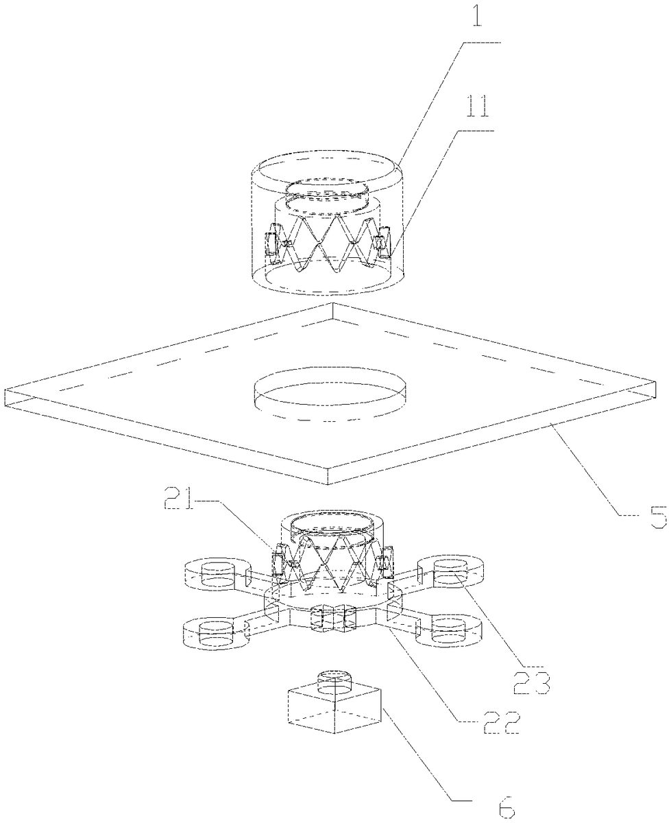
As shown inFIG. 1andFIG. 2, an embodiment of the present disclosure provides a button, comprising a cylindrical button cap1and a cylindrical button bracket2. The button bracket2is provided with a first magnetic connector3, and the button cap1is provided with a second magnetic connector4at a corresponding position. The button cap1is covered on the button bracket2, and the button cap1and the button bracket2are connected by a magnetic attraction force between the first magnetic connector3and the second magnetic connector4, thereby realizing the axial fixing between the button cap1and the button bracket2.
The button cap1and the button bracket2are also provided with a circumferential limiting assembly to realize the circumferential fixing between the button cap1and the button bracket2, so as to prevent the button cap1from rotating circumferentially when the button is pressed. In a particular embodiment of the present disclosure, the circumferential limiting assembly comprises sawtooth structures11,21that are provided along the periphery of an inner side wall of the button cap1and along the periphery of an outer side wall of the button bracket2and that are engageable.
The first magnetic connector3is a ferromagnetic material, and the second magnetic connector4is a magnetically attractable material, such as iron, nickel and other materials that can be magnetically attracted.
Alternatively, the second magnetic connector4is a ferromagnetic material, and the first magnetic connector3is a magnetically attractable material.
Alternatively, both of the first magnetic connector3and the second magnetic connector4are ferromagnetic materials.
When the button cap1needs to be replaced, the only condition to be satisfied is that the external force applied is greater than the magnetic attraction force between the first magnetic connector3and the second magnetic connector4, so the operation is simple and does not require any professional skill, and the internal structure of the product will not be damaged. Moreover, the button caps1of different colors, different hardness and different hand feelings may be replaced, so it is suitable for users who have different needs and preferences for the buttons.
When the button cap1is reinstalled, after the button cap1is covered on the button bracket2, by the attraction by the magnetic attraction force, the sawtooth structures on the button cap1and the button bracket2are automatically engaged to realize the positioning and circumferential fixing between the button cap1and the button bracket2, and the button cap1does not need to be rotated and fixed to a certain fixed orientation of the button bracket2, as in the prior art, so the installation is convenient.
In an embodiment of the present disclosure, the top portion of the button bracket2is provided with a first mounting recess for mounting the first magnetic connector3, and the corresponding position of the button cap1is provided with a second mounting recess for mounting the second magnetic connector4.
In an embodiment of the present disclosure, the edges of the sawtooth structures are straight lines. In another embodiment of the present disclosure, as shown inFIG. 3, the edges of the sawtooth structures are arcs. Compared with the straight line shaped sawtooth structures, the engaging process of the arc shaped sawtooth structures is smoother when they are automatically engaged by the attraction by the magnetic attraction force.
In an embodiment of the present disclosure, the height of the sawtooth structures may be adjusted as needed. The heights of the sawtooth structures11,21may be less than half of the height of the button cap1, and may also be greater than half of the height of the button cap1, as long as the engagement and fixing between the button cap1and the button bracket2can be achieved.
As shown inFIG. 1andFIG. 2, elastic arms22are symmetrically provided at the bottom of the button bracket2. For example, the number of the elastic arms22may be two or four, etc. The elastic arms22are parallel to a plane of the bottom of the button bracket2. A mounting hole23is provided at the tip end of each of the elastic arms22, and a screw is screwed into the mounting hole23to fix the button bracket2to a panel5at the button mounting position. The elastic arms22have elasticity, and after the external pressing force applied to the button is cancelled, the elastic arms22drive the button bracket2to rebound and reset.
As shown inFIG. 2, a boss24corresponding to a button element6at a button mounting position is provided at the bottom of the button bracket2. When the button cap1is pressed, the boss24contacts and presses the button element6at the corresponding position, so that the electrical circuit corresponding to the button element6is closed.
As shown inFIG. 4, an embodiment of the present disclosure further provides a game controller comprising an upper casing7, a lower casing8and the above-mentioned buttons.
An embodiment of the present disclosure further provides a remote controller comprising the above-mentioned buttons.
While at least one exemplary embodiment has been presented in the foregoing detailed description, it should be appreciated that a vast number of variations exist. It should also be appreciated that the exemplary embodiment or exemplary embodiments are only examples, and are not intended to limit the scope, applicability, or configuration of the invention in any way. Rather, the foregoing detailed description will provide those skilled in the art with a convenient road map for implementing an exemplary embodiment, it being understood that various changes may be made in the function and arrangement of elements described in an exemplary embodiment without departing from the scope of the invention as set forth in the appended claims and their legal equivalents.
Claims
- A button, comprising: a cylindrical button cap and a cylindrical button bracket, wherein the button bracket is provided with a first magnetic connector, and the button cap is provided with a second magnetic connector at a corresponding position;the button cap is covered on the button bracket, and the button cap and the button bracket are connected by a magnetic attraction force between the first magnetic connector and the second magnetic connector, thereby realizing the axial fixing between the button cap and the button bracket;and the button cap and the button bracket are further provided with a circumferential limiting assembly to realize the circumferential fixing between the button cap and the button bracket, so as to prevent the button cap from rotating circumferentially when the button is pressed.
- The button according to claim 1 , wherein the circumferential limiting assembly comprises: sawtooth structures that are provided along a periphery of an inner side wall of the button cap and along a periphery of an outer side wall of the button bracket and that are engageable, and edges of the sawtooth structures are straight lines or arcs.
- The button according to claim 1 , wherein a top portion of the button bracket is provided with a first mounting recess for mounting the first magnetic connector, and a corresponding position of the button cap is provided with a second mounting recess for mounting the second magnetic connector.
- The button according to claim 1 , wherein the first magnetic connector is a ferromagnetic material, and the second magnetic connector is a magnetically attractable material;or, the second magnetic connector is a ferromagnetic material, and the first magnetic connector is a magnetically attractable material;or, both of the first magnetic connector and the second magnetic connector are a ferromagnetic material.
- The button according to claim 1 , wherein elastic arms are symmetrically provided at a bottom of the button bracket and are parallel to a plane of the bottom of the button bracket;and a mounting hole is provided at a tip end of each of the elastic arms, and a screw is screwed into the mounting hole to fix the button bracket to a panel at a button mounting position.
- The button according to claim 5 , wherein: the number of the elastic arms is two or more;and the elastic arms have elasticity, and after the external pressing force applied to the button is cancelled, the elastic arms drive the button bracket to rebound and reset.
- The button according to claim 1 , wherein a boss corresponding to a button element at a button mounting position is provided at a bottom of the button bracket.
- A game controller comprising a button, the button comprising: a cylindrical button cap and a cylindrical button bracket, wherein the button bracket is provided with a first magnetic connector, and the button cap is provided with a second magnetic connector at a corresponding position;the button cap is covered on the button bracket, and the button cap and the button bracket are connected by a magnetic attraction force between the first magnetic connector and the second magnetic connector, thereby realizing the axial fixing between the button cap and the button bracket;and the button cap and the button bracket are further provided with a circumferential limiting assembly to realize the circumferential fixing between the button cap and the button bracket, so as to prevent the button cap from rotating circumferentially when the button is pressed.
- A remote controller comprising a button, the button comprising: a cylindrical button cap and a cylindrical button bracket, wherein the button bracket is provided with a first magnetic connector, and the button cap is provided with a second magnetic connector at a corresponding position;the button cap is covered on the button bracket, and the button cap and the button bracket are connected by a magnetic attraction force between the first magnetic connector and the second magnetic connector, thereby realizing the axial fixing between the button cap and the button bracket;and the button cap and the button bracket are further provided with a circumferential limiting assembly to realize the circumferential fixing between the button cap and the button bracket, so as to prevent the button cap from rotating circumferentially when the button is pressed.
- The remote controller according to claim 9 , wherein the circumferential limiting assembly comprises: sawtooth structures that are provided along a periphery of an inner side wall of the button cap and along a periphery of an outer side wall of the button bracket and that are engageable, and edges of the sawtooth structures are straight lines or arcs.
- The remote controller according to claim 9 , wherein a top portion of the button bracket is provided with a first mounting recess for mounting the first magnetic connector, and a corresponding position of the button cap is provided with a second mounting recess for mounting the second magnetic connector.
- The remote controller according to claim 9 , wherein: two or more elastic arms are symmetrically provided at a bottom of the button bracket and are parallel to a plane of the bottom of the button bracket;the elastic arms have elasticity, and after the external pressing force applied to the button is cancelled, the elastic arms drive the button bracket to rebound and reset;and a mounting hole is provided at a tip end of each of the elastic arms, and a screw is screwed into the mounting hole to fix the button bracket to a panel at a button mounting position.
- The remote controller according to claim 9 , wherein a boss corresponding to a button element at a button mounting position is provided at a bottom of the button bracket.
- The game controller according to claim 8 , wherein the circumferential limiting assembly comprises: sawtooth structures that are provided along a periphery of an inner side wall of the button cap and along a periphery of an outer side wall of the button bracket and that are engageable, and edges of the sawtooth structures are straight lines or arcs.
- The game controller according to claim 8 , wherein a top portion of the button bracket is provided with a first mounting recess for mounting the first magnetic connector, and a corresponding position of the button cap is provided with a second mounting recess for mounting the second magnetic connector.
- The game controller according to claim 8 , wherein: two or more elastic arms are symmetrically provided at a bottom of the button bracket and are parallel to a plane of the bottom of the button bracket;the elastic arms have elasticity, and after the external pressing force applied to the button is cancelled, the elastic arms drive the button bracket to rebound and reset;and a mounting hole is provided at a tip end of each of the elastic arms, and a screw is screwed into the mounting hole to fix the button bracket to a panel at a button mounting position.
- The game controller according to claim 8 , wherein a boss corresponding to a button element at a button mounting position is provided at a bottom of the button bracket.
Disclaimer: Data collected from the USPTO and may be malformed, incomplete, and/or otherwise inaccurate.