U.S. Pat. No. 10,406,434
VIDEO GAME CONTROLLER USING CORE MUSCLES AND OTHER APPLICATIONS
AssigneeAlert Core, Inc.
Issue DateJuly 7, 2016
Illustrative Figure
Abstract
A wearable device has a core contraction sensor and a movement sensor which transmits signals to a processor which analyzes the signals and uses the data to control aspects of a video game. The core contraction signal may determine if the user's core is contracted or relaxed. A video game may be used with the wearable device to encourage usage of the core muscles with the player getting points or rewards for engaging their core muscles and properly timing the engagement of the core muscles with body movements. The wearable device may be used in place of, or together with conventional video game control devices. Developing the habit of using the core muscles during may be beneficial in back pain rehab and prevention, fitness training and wellness, athletic performance improvement, and reducing workplace injuries in occupations involving heavy lifting.
Description
DETAILED DESCRIPTION In U.S. Pat. No. 9,226,706, an inventive device and system is described, one embodiment of which enables real-time tracking of the core muscles by tracking core muscle contraction with a core contraction sensor and body movements with a movement sensor. The inventive device and system encourage the development of procedural memory for usage of the core muscles. The core contractions can then be used during Qualifying Movements (QMs) which are defined as movements for which contraction of the core muscles may be beneficial in supporting the lumbosacral junction and lumbar spine. In an application, when a QM is identified by the system, the system determines whether or not the QM is protected or not protected based on the status of the user's core before, during, and after the QM. The wearable device and system may be used to develop a sequenced core, that is core muscle engagement that is deliberate and coordinated with other body movements. In this current description, an inventive system is described to utilize the wearable device as an input controller to video games for the purpose of encouraging and teaching a user-player of the video game system to use their core muscles more effectively and in a coordinated manner with movements of their body. The system may also be beneficially used for teaching preferred ways to perform specific movements that may have benefit for reducing stress on the spine and other parts of the body. There are a wide variety of controllers used to control athletic equipment, avatars, weapons, vehicles, people and other objects in video games today. Joysticks were used predominantly in the early days of video games back in the 1970's and they are still widely used today. Moving an object or avatar left or right in one-dimensional control; left, right, forward, ...
DETAILED DESCRIPTION
In U.S. Pat. No. 9,226,706, an inventive device and system is described, one embodiment of which enables real-time tracking of the core muscles by tracking core muscle contraction with a core contraction sensor and body movements with a movement sensor. The inventive device and system encourage the development of procedural memory for usage of the core muscles. The core contractions can then be used during Qualifying Movements (QMs) which are defined as movements for which contraction of the core muscles may be beneficial in supporting the lumbosacral junction and lumbar spine. In an application, when a QM is identified by the system, the system determines whether or not the QM is protected or not protected based on the status of the user's core before, during, and after the QM. The wearable device and system may be used to develop a sequenced core, that is core muscle engagement that is deliberate and coordinated with other body movements.
In this current description, an inventive system is described to utilize the wearable device as an input controller to video games for the purpose of encouraging and teaching a user-player of the video game system to use their core muscles more effectively and in a coordinated manner with movements of their body. The system may also be beneficially used for teaching preferred ways to perform specific movements that may have benefit for reducing stress on the spine and other parts of the body.
There are a wide variety of controllers used to control athletic equipment, avatars, weapons, vehicles, people and other objects in video games today. Joysticks were used predominantly in the early days of video games back in the 1970's and they are still widely used today. Moving an object or avatar left or right in one-dimensional control; left, right, forward, backward, and in combination for two-dimensional control is what a joystick has been used for since the early days of video gaming. With an additional joystick, the control of up and down can be added to the two-dimensional controller for control in three-dimensions.
Recently introduced video game platforms such as Xbox Kinect by Microsoft Corporation have popularized video sensing where the body movements of a player are tracked and used to control avatars or other objects. The Microsoft Corporation Xbox Kinect uses video images and an infrared sensor to resolve distance allowing it to identify and track body movements and body positioning. Players simply stand in front of the specialized camera, move their bodies, and their movements are converted to data that can be used to control an avatar or other object in a video game. The Sony Playstation Move Controller uses a wand-like device that may be moved in 3-D space by a player's hand and the movements are tracked using inertial navigation with sensors including accelerometers, gyros, and a magnetometer. The sensor movements are then sent wirelessly to a controller box which converts the player's movements into the movement of an avatar or other objects in a video game. The use of inertial navigation using low-cost sensors has become widely used in video gaming.
User body movements for controlling an avatar or object in a video game has brought on a new generation of games and ways of playing and interacting with games. Players are able to get exercise with the controllers that utilize body movements. 3-D glasses are enabling yet another approach to present video games to players. 3-D glasses in video gaming is still being improved but promises to allow players to interact with game environments in new and even more lifelike ways.
Video games are generally played by players for entertainment. Some games provide additional utility by encouraging players to perform body movements resulting in players receiving the benefit of exercise. Some of these games are used in physical therapy to encourage patients to move in specific and beneficial ways.
The inventive system described in U.S. Pat. No. 9,226,706 enables real time tracking of the inner core muscles. Furthermore, it encourages the development of procedural memory for support of a user's lumbosacral junction and lumbar spine by encouraging a user to contract their core muscles before and during performing Qualifying Movements.
There are no games available today that encourage a player of a video game to deliberately contract their core muscles before or in combination with body movements as a training or development tool for improved health and usage of core muscles. This current invention brings the motivational and entertainment value of video games into the learning process of using the core muscles more effectively. Different timing models of core contraction and body movements may be encouraged. For example, a user or player of the game may be encouraged to contract their core before and during movements, during movements, and before, during and after movements. Players may be encouraged to contract their core for some movements and not others. The preferred contraction patterns may also be conditional, depending on the magnitude of a movement or the speed of the movement. In the following, the terms user and player will be used interchangeably.
A user may be encouraged to use their core in conjunction with specific movements by receiving points for performing certain combinations of core contraction and movements and by not receiving points for performing certain combinations of core contraction and movements. The avatar or object under control may move when the core is contracted during a movement of the player's body and not move when the player's core is not contracted in a specific preferred way. For example, an object in a video game may move to the right when a standing user slides to their right or the object may move to the left when a standing user slides to their left only when the player contracts their core prior to sliding to the right or left throughout the duration of the slide. In another embodiment, the object may slide if the player contracts their core during a substantial portion of the duration of the slide. Timing requirements of the core contraction in relation to a movement of a player's body enabling movement of an object in a video game may be modified in software. The magnitude that the object in the video game moves to the left or right may be substantially proportional to the distance that the player slides to the left or right with their core appropriately contracted.
The concepts presented describe using body movements of a user wearing the wearable device converted to similar movements of an avatar or object in a video game when the user's core is contracted appropriately. This concept is very general and may be applied to many types of video games. The invention can be beneficial to most users who want to learn to more effectively utilize their core muscles. The invention may also be beneficial for those in therapy for back pain. Video game content, player movements and core usage may be designed for therapeutic and rehabilitation applications, as well as building muscle memory or neural patterning for core usage in health and fitness, wellness, athletic performance improvement, and workplace injury reduction.
Referring toFIG. 1, a block representation of a typical video game system is shown. The user or game player101interacts with the video game by controlling Game Interface501. Examples of Game Interface501include joysticks; embedded sensors in state-of-the-art smart phones, smart pads, and smart watches; steering wheels; flight controllers; guns; music instrument emulators; computer keyboards; computer touch pads; computer mice; foot pedals; and proprietary controllers such as Microsoft Corporation's Xbox Kinect sensor camera and the Sony PlayStation Move Motion Controller. Game Interface501converts movements of the user or player101into signals that are processed by Processor507and used to control an avatar or an element in a Game Scene509shown on a Display505. Sound Generator511generates and drives audio signals through a speaker or headphone system. The Game Device503may include a display505, processor507, Sound Generator511, and Memory513. Memory513may include storage for storing programs for different games. It may also include memory that is used by the processor during the execution of program code to execute a game.
The game device503may be a PC or processor-based controller with a built-in or external monitor, smart phone or other handheld or countertop device containing a processor and a display. The display505may show an avatar or object that moves in response to the signal received from the Movement Sensing Device501in response to user101movements. In some video games, the surroundings of the avatar or object move relative to a stationary avatar or object creating the illusion that the avatar or object is moving. Processor507communicates with movement sensing device501and runs the software to execute the game. Communication blocks exist on both the Game Interface501and Game Device503but are not shown explicitly. These communication blocks may be wired or wireless.
An embodiment of the inventive system is shown inFIG. 2. Player101has attached the wearable device103. Data from the wearable device103may be combined with data from Game Interface501by data combiner515to form composite data that communicates with processor507which is part of Game Device503. In an embodiment, data combiner515is implemented in Game Device503. Communication blocks may be present in Game Interface501, wearable device103, and Game Device503and are not shown explicitly. These communication blocks may be wired or wireless. In an embodiment, wearable device103communicates to Game Device503via a wireless link and Game Interface501communicates with Game Device503via a wired link. In another embodiment, both wearable device103and Game Interface501communicate with Game Device503over a wireless link.
The addition of wearable device103may enable new learning features in video games. Core contraction sensor data and movement sensor data from the wearable103may be converted to video signals. In some embodiments, video signals may include video game scenarios that may be devised to encourage or elicit specific physical responses or actions by a player. The player may be encouraged to respond with certain movements or combinations of movements including appropriately timed core contractions. The core contraction sensor on the wearable103may be utilized to combine core contraction and core contraction timing with body movements in the video game. Some aspects of conventional Game Interface501may be utilized for control data in the video game. In some applications, only data from the wearable device103may be used. In other applications, data from the core contraction sensors on the wearable device103may be used with data from the Game Interface501. In other applications, data from the movement sensors on the wearable device103may be used with data from the Game Interface501.
In some applications, video game software may be written specifically to encourage core muscle usage and the development of a sequenced core. In such specific video games, the games may be written exclusively for wearable device103. In these specific video games, wearable device103may be the exclusive source of player101control data or provide partial control data that may be combined with Game Interface501control data. These specific video games may emphasize core contractions and timing core contractions with body movements.
In other applications, the wearable device may be used partially or exclusively as the Game Interface501to games that were not written specifically for wearable device103. In such non-specific video game applications, an Application Program Interface (API) may be utilized. An API is a set of tools for building software applications and may facilitate interfacing wearable device103with non-specific video games. An API may facilitate the development of a software driver that may run on processor507to translate player101actions detected by the wearable device103sensors into commands for the non-specific video games. At a basic level of abstraction, the core contraction sensor may for example send out data to the system informing when the player's101core muscles transition firstly from relaxed to engaged, and secondly from engaged to relaxed. This may be defined in an API for the wearable device103to facilitate interfacing the wearable device103to non-specific video games. In an embodiment where a non-specific video game is designed to perform a function upon a mouse click, a software driver may be used to perform the function when wearable device103detects a transition from a relaxed to engaged core. The API may also be used to facilitate enabling any programmer to write a specific video game software to work with the wearable device103.
An embodiment of the inventive system is shown inFIG. 3where the program code for the video game is run on a processor507on a remote server516. Cloud gaming is an example of this system configuration. The player101may wear the wearable device103and interact with the Game Interface501. The output of the wearable device103and Game Interface501may be combined and used as player data for the video game. This player data may be sent over communication block512in the Game Device503over the Internet514to the remote server516. The video game program code may be run on a processor507on the remote server516, and video and sound data may be sent back in real-time from the communication block512on the remote server516, over the Internet514, and to the communication block512on the game device503. The processor507on the game device503may convert the video data into a video signal for display505. The processor507on the game device503may convert the audio data into an audio signal and the audio signal may be output via a sound generator511on the game device503. This configuration where the game is run on a remote processor may make an assortment of video games very accessible to users.
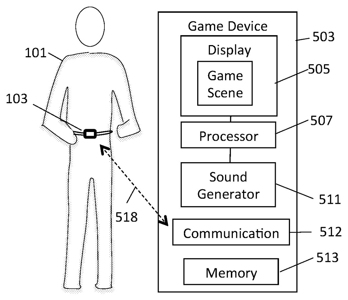
With reference toFIG. 4a, a player101is shown with wearable device103worn over the core muscles. Wearable device103communicates with communication block512on the game device503. In an embodiment, wearable device103communicates with game device503over wireless link518. InFIG. 4b, a player101is shown with wearable device103worn over the right VMO. Wearable device103communicates with communication block512on the game device503. In an embodiment, wearable device103communicates with game device503over wireless link518.FIGS. 4aand 4billustrate the player101, wearable device103, and game device503in simple embodiments.
The wearable device103may be used to control a video game in different ways. In one embodiment called Movement Criteria Mode, Movement Criteria are evaluated for each movement using body movement sensor data and core contraction sensor data. In an embodiment, the timing relationship between core contraction and body movements and other parameters of the movement data may be evaluated against Movement Criteria. If Movement Criteria are met, the player's movement may be translated into something favorable in the video game. If Movement Criteria are not met, the player's movement may result in no movement or something unfavorable in the video game.
In another embodiment, the wearable device103provides additional player101control data directly, without evaluating timing relationships between the contraction sensor data and the movement sensor data. This is called Direct Movement Mode and data from the wearable device103may add to or replace the Game Interface to allow the player101to interact with the video game via the wearable device103.
In Direct Movement Mode, as the player101moves their body, the wearable103will move. The movements may be detected by the movement sensor and translated into position changes in three dimensions. Depending on the avatar or object being controlled in the video game, this may be translated on the display as an equivalent change of the avatar or object in one, two, or three dimensions. The change in position may be proportional or non-linear, depending on the application. In a proportional change, if the player101moves to the right by one inch, the avatar or object may move equivalently to the right by one unit of distance. If the player101moves to the right by two inches, the avatar or object will move equivalently to the right by approximately two units of distance. In a non-linear change in position of the avatar or object, if the player101moves to the right by two inches, the avatar or object may move equivalently to the right by substantially less than two units of distance, for example one-and-a-half units of distance, or substantially more than two units of distance, for example three units of distance.
A flow diagram of Movement Criteria Mode is shown inFIG. 5. Begin by placing the wearable103on the player101and set up the system to enable the player movements to control an avatar or object in a video game601. Next, monitor the player's101body movements and core contraction activity with the sensors on the wearable device603. Movement Criteria are additional qualifications that may be placed on how and when the user contracts their core in relation to how they move. Example of Movement Criteria will be provided shortly. The next step in the flow diagram is to check whether or not Movement Criteria are met by the current user movement605. If the Movement Criteria test605is not met, Ramification or Ramifications609result. This will have a detrimental effect on the users score or performance in the game. Examples of Ramifications609will be provided shortly. Finally, if the Movement Criteria test605are met, then the player's movements are translated into a Favorable607result, for example it may result in expected movements of the avatar or object, or points added to a player's101score.
Examples of Movement Criteria which may be combined or used in isolation depending on the application include but are not limited to:
A. The user must move from one position to a second position, and pause for a minimum duration of time, for example 250 msec before moving to a third position;
B. The discrete movements in A with pauses in between must be appropriately protected with contraction of the core muscles prior to the movements;
C. Only protected qualifying movements move the avatar or object correctly; or
D. Protected qualifying movements may require the core contraction begin before and throughout the entire movement;
The parameters and content of Movement Criteria tests605may be modified based on a number of factors. Examples of factors that may change or adjust Movement Criteria include a player's performance during a game or series of games, a player's pain condition, and a player's skill level in using their core muscles.
When one or more Movement Criteria are not met by a player's101body movements and core contraction during a movement during a game, a Ramification609may occur. A number of Ramifications609are possible. Ramifications609may occur in isolation or in combination. Examples of Ramifications609include no movement of the avatar or object in response to the movement of the player, partial or incorrect movement of the avatar or object in response to the movement of the player, negative points added to the player's score, demerits added to the player's score, or modifications to the content or parameters of the Movement Criteria.
In some embodiments, the data from the wearable device103may be converted to video signals that are output on a video display wherein the video signals include game scenarios, player movements, and Favorables and Ramifications in numerous and varied ways. A few such embodiments are shown in the table ofFIG. 5b. The avatar column602describes the embodiment of the avatar. The game challenge column604describes a challenging scenario that the avatar may be confronted with in the course of the video game. The desired player movement column606describes the movement including core contraction that the player must perform in order to get a favorable response to the avatar. The sensor signals column608includes the sensor or sensors that may be used to determine video feedback signals610. Video feedback signals610contains two columns. The favorable column608describes a favorable action to the avatar in response to the player performing the desired player movement606. The ramification column610describes a negative action to the avatar in response to the player not performing the desired player movement606. For example, in the first row, the avatar602is a race car. The game challenge604may be to race on a course with at least one other race car. The desired player movement606may be for the player to engage their core muscles. The sensor used 608 may be the core contraction sensor. Based on the core contraction signal, a core contraction video feedback signal610that may be output on a video display may be favorable612and the race car speed may increase or a ramification614, wherein the race car speed may be a slow speed.
An avatar may include blocks, squares, rectangles, balls, circles, triangles, food objects, animals, plants, insects, fantasy objects like magic wands or unicorns, or other objects. This table is an example of a video game objective, a player's required movement to achieve the objective, and the results of the player performing the movement correctly or incorrectly. Many applications and game scenarios are possible.
An example of a ping pong game is illustrated inFIG. 6. This game is called Pong and was made popular in the 1970s by Atari Incorporated. A player may play against the computer as shown in this example. The player's101racket565is on the left half and the computer's racket567is on the right half of the game table551. Ball569bounces off table sides553,555but will go out the ends575,577. If ball569goes out the left end575, a point goes to the computer. If ball569goes out the right end577, a point goes to the player. The path of the ball571is shown bouncing off the player's paddle565and moving in the direction of the computer's half of the table. The net573separates the player's half on the left from the computer's half on the right. From the player's perspective on the left half, the paddle may move left561and right563based on the user's101control of the movement sensor inside wearable device103.
An embodiment of the system is now described. An example of a player's101movement resulting in movement of the wearable103in the left and right direction as a function of time is shown inFIG. 7a. An example of a player's101core status, whether contracted595or relaxed596as a function of time is shown inFIG. 7b.FIG. 7cshows the resulting paddle movement as a function of time using an embodiment of the Movement Criteria. Items inFIGS. 7a, 7b, and 7care shown aligned in time.
Referring toFIG. 7a, the player first moves left581with core contracted595as shown inFIG. 7b. This meets Movement Criteria, resulting in paddle movement to the left591. The core is then relaxed596and then contracted595again prior to a move back to the right583. This again meets Movement Criteria, resulting in paddle movement back to the right593. Next, the player moves right585but since core is still relaxed596, Movement Criteria is not met and the Ramification609is a non-movement of the paddle. Following this, left movement587occurs when core is contracted595and the paddle moves left597. Core then relaxes596, contracts595, and relaxes596again. Since there is no player movement, there is no paddle movement. Finally, the player moves left589with core relaxed596so paddle does not move until core is contracted595, resulting in a smaller paddle move left599than would have occurred had core been contracted throughout the move left589. In another embodiment of the Movement Criteria, since the core is relaxed596at the start of movement left589, the paddle may not move at all in response to movement left589.
Referring toFIG. 8, a visual from a basic shooter game is shown. Concentric ovals651enter from the top and move down to the bottom then out of the display. Centered at the bottom of the display is a shoot barrel653that shoots balls655in the direction the barrel is pointing. The player101controls the direction of the barrel653and controls when the balls655are shot from the barrel653. In an embodiment, the direction of the barrel652is controlled by rotation of the player's101torso. In an embodiment, the barrel653rotates only when the player101engages the core muscles prior to the rotation. In another embodiment, a computer keyboard is used as a game interface501. For some video game applications, the “a” key moves items left and the “d” key moves items right. In an application where the game is played on a computer, when the “a” key is pressed, the barrel653may rotate left and when the “d” key is pressed, the barrel653may rotate right. In an embodiment, the barrel653shoots a ball when the player101engages their core muscles. Each time the core muscles transition from relaxed to engaged, the transition is detected by the core contraction sensor on the wearable device103and a ball is fired. In an embodiment, the wearable device103communicates via a wireless link such as Bluetooth to the computer. A software driver may be used on the computer to interpret the data from the wearable device103, and identify the transitions from a relaxed to engaged core and result in a ball655being shot from the barrel653in the video game.
Referring toFIG. 9, an embodiment with a system that generates a 3-D model of a player including a camera657, game controller659, and display505is shown. Wearable device103may be worn over the core muscles of player101. The game controller659includes a communication block512to communicate with wearable device103. In an embodiment, communication between the wearable device103and the communication block512in the game controller659over a wireless communication link518. Game controller659takes data from the camera657and converts it into a 3-D model of the player in real-time. Digital signal processing techniques may be applied using the data from two or more cameras for identifying depth in order to build a 3-D model. In an embodiment with a real-time 3-D model of the player and real-time tracking of the core muscles, a video game to encourage contracting the core muscles coordinated with body movements may be implemented to develop muscle memory for athletic movements that can be practiced daily in the player's101home. In the example shown inFIG. 9, the player is practicing engaging the core muscles before a back swing in golf. The player may hold a stick671to mimic the feel of a golf club. By practicing this sequence of movements in the video game, a player may develop the habit to engage their core muscles prior to a golf back swing. Engaging the core muscles during a golf swing is one example of a movement that may benefit from support of the core muscles. Utilizing the video game may allow a player101to practice regularly at home and may facilitate the development of procedural memory, muscle memory, or neural patterning to help turn the practice of core engagement during a golf swing into a habit.
In U.S. Pat. No. 9,226,706 and U.S. patent application Ser. Nos. 14/132,808, 14/789,136, 14/652,542, 14/817,964, 61/739,160, and 62/154,626, various approaches may be utilized to implement the core contraction sensor.FIG. 10illustrates an exploded view of an embodiment utilizing a Force Sensing Resistor (FSR)173on the top of the figure while a cross-sectional view is shown at the bottom of the figure. Starting at the upper left and moving to the right, the exploded view includes the device103with volume removed171to custom fit a force sensing resistor173with active area172, a bumper175that may be implemented with a rubber or rubber-like material with a brim, and a frame177that holds the force sensing resistor or FSR173and bumper175in place by holding the brim in place. The frame177may be attached to the device using glue or one or more screws or other attachment materials. Additional features may be designed into the brim of the bumper including an O-ring in order to promote water resistance in the design. In the cross-sectional view, the deepest cavity is where the FSR173may reside. Above the cavity for the FSR173is a cavity where the brim of the bumper175may reside. Above the bumper brim is a cavity to fit the frame177which attaches to the device body103to hold in place the FSR173and the bumper175. Note in the cross-sectional view that the bumper175may have a small extrusion underneath it to interface to the active portion of the FSR173. In an embodiment, the feature of the bumper175that interfaces to the user's103core may be shaped to achieve the objectives of comfort and sensitivity. In the example shown, the section of the bumper that will interface to the user's core is shown to be rounded. In an embodiment, the bumper may have a substantially flat area on the tip that interfaces to the user's core muscles while having a rounded top rim.
Referring toFIGS. 11a, an embodiment of an extender cap181may be added to the top of the bumper175to further extend the effective height and girth of the bumper175. Referring toFIG. 11b, mushroom cap193is shown. Mushroom cap193is similar to extender cap with the feature that the area of the effective bumper against the body is increased while the height of the bumper is not appreciably increased or increased at all. The mushroom cap193may result in greater comfort to the user by reducing the apparent sharpness of the bumper against the users muscles. In an embodiment, a flat ring191may be placed around the bumper on the face of the wearable device. The ring191may keep the mushroom cap193from pressing down directly into the face of the wearable device103when pressure is placed on an outside edge of the mushroom cap193, and reduce bending of the column region of the rubber bumper175. In an embodiment, the ring191may be made from a firm pliable material such as felt, neoprene, or material with similar properties. In some applications, an extender feature may be added to the top of the mushroom cap191and bumper175in order to increase the height of the contraction sensor. InFIG. 11c, a view of the top portion of the rubber bumper is shown from an angle with mushroom cap191shown separated from the bumper. The mushroom cap193may be held in place via a snug fit or with an adhesive such as glue, double stick tape, or other adhesive.
Referring toFIG. 12a, forces are indicated by arrows and an applied force196is shown applied to the right edge of mushroom cap193. As a result, mushroom cap193presses against frame177resulting in a force198which opposes the downward component of force196, and reduces force200against the FSR173. While it is desirable to increase the girth of the mushroom cap193in order to have a larger area to couple to muscles, in many applications, the forces on the bumper175with the mushroom cap193may have one or more significant components that are not normal to the face of the device103.
Referring toFIG. 12b, an embodiment with two bumpers175is shown with unifier cap194. Unifier cap is similar to mushroom cap193as it increases the effective girth of the bumpers in order to provide a larger area to couple to the user's muscles. An important feature of the unifier cap194is that it may be designed so that even in the presence of forces not normal to the face of the device103, the unifier cap194may not contact the frame177or the body of device103.
In an embodiment, the height of the unifier cap194may be increased using unifier cap extender621as shown inFIG. 13a. An embodiment to attach unifier cap extender621to unifier cap194is shown inFIGS. 13aand 13bwhere clips623slide in through holes625that then hook onto the inside surface of unifier cap194. Other approaches for attaching unifier cap extender621to unifier cap194may be utilized.
Referring toFIG. 14a, an embodiment with two bumpers175is shown. A Y-axis615and X-axis613. Unifier cap194is shown surrounding both bumpers175. In order to ensure unifier cap194does not contact the frame177or face of the device103when a force is applied at an angle of the edge of the unifier cap194, unifier cap194is designed to be only slightly wider in the Y-dimension615as the bumper diameter. InFIG. 14b, an embodiment with three bumpers175is shown. Unifier cap194has larger size in the Y-dimension compared with the unifier cap194in the two bumper design. For some applications, the three bumper design is desirable since it results in a significant increase in the area of unifier cap194.
In applications where two or more bumpers are used and FSRs are used as force sensors, separate FSRs may be used and placed beneath the bumpers and the outputs of the FSRs may be sensed independently. In another application, a custom FSR with multiple sensors placed beneath each bumper may be used. Electrically, each of the sensors in the multiple sensor FSR may be in parallel. Other configurations and FSR structures may be utilized. Optimizing the FSR shape and design with placement of the bumpers with similar shapes to optimally couple the FSR to the bumpers may be desirable for some applications.
In some applications, more than one wearable device may be simultaneously utilized. Multiple devices may allow more than one muscle to be monitored simultaneously. Multiple devices may allow the core muscles to be monitored in different positions simultaneously. The use of multiple wearable devices may reduce the likelihood of missing the detection of a core contraction or a muscle contraction. An embodiment employing two wearable devices103is shown inFIG. 15where both devices are used to monitor the core muscles. In some applications, wireless standards common on some smart devices may support connection between an app running on the smart device to one wearable device at a time. In an embodiment, a first wearable device103establishes a wireless connection to smart device503over wireless link518. Then, a second wearable device103may be connected via a wired link520to the first wearable device103. In an embodiment, the wired link520may be a USB link. The second wearable device103may transmit via wired link520to the first wearable device103. And the first wearable device103may transmit sensor data and derived data from both the first wearable device and the second wearable device to the smart device503. In an embodiment, an app may run on smart device503and may communicate via audio and a display to the user, and may receive data from the first wearable device103and the second wearable device103. Control data may be transmitted from the app running on smart device503via the wireless link518to the first wearable device103and the first device may transmit via wired link520the control data to the second wearable device103.
The terminology used herein is for the purpose of describing particular embodiments only and is not intended to be limiting of the invention. As used herein, the singular forms “a”, “an” and “the” are intended to include the plural forms as well, unless the context clearly indicates otherwise. It will be further understood that the terms “comprises” and/or “comprising,” when used in this specification, specify the presence of stated features, integers, steps, operations, elements, and/or components, but do not preclude the presence or addition of one or more other features, integers, steps, operations, elements, components, and/or groups thereof.
Some embodiments of the invention are implemented as a program product for use with an embedded processor. The program(s) of the program product defines functions of the embodiments (including the methods described herein) and can be contained on a variety of signal-bearing media. Illustrative signal-bearing media include, but are not limited to: (i) information permanently stored on non-writable storage media; (ii) alterable information stored on writable storage media; and (iii) information conveyed to a computer by a communications medium, such as through a computer or telephone network, including wireless communications. The latter embodiment specifically includes information downloaded from the Internet and other networks. Such signal-bearing media, when carrying computer-readable instructions that direct the functions of the present invention, represent embodiments of the present invention.
In general, the routines executed to implement the embodiments of the invention, may be part of an operating system or a specific application, component, program, module, object, or sequence of instructions. The computer program of the present invention typically is comprised of a multitude of instructions that will be translated by the native computer into a machine-accessible format and hence executable instructions. Also, programs are comprised of variables and data structures that either reside locally to the program or are found in memory or on storage devices. In addition, various programs described hereinafter may be identified based upon the application for which they are implemented in a specific embodiment of the invention. However, it should be appreciated that any particular program nomenclature that follows is used merely for convenience, and thus the invention should not be limited to use solely in any specific application identified and/or implied by such nomenclature.
The present invention and some of its advantages have been described in detail for some embodiments. It should be understood that although the process is described with reference to a device, system, and method for developing core contraction procedural memory, the process may be used in other contexts as well. It should also be understood that various changes, substitutions and alterations can be made herein without departing from the spirit and scope of the invention as defined by the appended claims. An embodiment of the invention may achieve multiple objectives, but not every embodiment falling within the scope of the attached claims will achieve every objective. Moreover, the scope of the present application is not intended to be limited to the particular embodiments of the process, machine, manufacture, composition of matter, means, methods and steps described in the specification. A person having ordinary skill in the art will readily appreciate from the disclosure of the present invention that processes, machines, manufacture, compositions of matter, means, methods, or steps, presently existing or later to be developed are equivalent to, and fall within the scope of, what is claimed. Accordingly, the appended claims are intended to include within their scope such processes, machines, manufacture, compositions of matter, means, methods, or steps.
Claims
- A method for improvement of core muscles based support, comprising: providing a core muscle contraction sensor, a movement sensor, a video game software program running on a processor, and a display in communication with the processor and a memory coupled to the processor;detecting core contractions of the user with the core muscle contraction sensor;transmitting core contraction signals from the core muscle contraction sensor to the processor;detecting body movements of the user with the movement sensor;transmitting body movement signals from the movement sensor to the processor;determining by the processor that the body movement signals either indicate that a desired player movement has been performed or that the desired player movement has not been performed;and converting by the video game program running on the processor, the desired player movements that have been performed which include the core contraction signals into video feedback signals that are output as positive actions of a visual object on a video game on the display and the desired player movements that have not been performed into the video feedback signals that are output as negative actions of the visual object on the video game on the display.
- The method of claim 1 further comprising: determining by the processor that the movement signals indicate a qualifying movement that benefits from the core contraction;and converting by the video game program running on the processor, the movement signals that indicate the qualifying movement into qualifying movement video feedback signals that are output on the display.
- The method of claim 2 further comprising: detecting by the processor, a timing relationship between the qualifying movement and the core contraction signals;identifying a protected qualifying movement when the core contraction signals occur throughout the qualifying movement;and converting by the video game program running on the processor, the protected qualifying movement into protected qualifying movement video feedback signals.
- The method of claim 3 further comprising: detecting by the processor, a timing relationship between the qualifying movement and the core contraction signals;identifying an unprotected qualifying movement when the core contraction signals does not occur throughout the qualifying movement;and converting by the video game program running on the processor, the unprotected qualifying movement into unprotected qualifying movement video feedback signals.
- The method of claim 4 wherein the protected qualifying movement video feedback signals are movements of an avatar in a first direction on the display.
- The method of claim 5 wherein the unprotected qualifying movement video feedback signals are movements of the avatar in a second direction on the display.
- The method of claim 5 wherein the unprotected qualifying movement video feedback signals are stopped movements of the avatar on the display.
- A method for improvement of core muscles based support, comprising: providing a contraction sensor, a movement sensor, a video game software program running on a processor, and a display in communication with the processor and a memory coupled to the processor;displaying a video game scenario on the display with a movable object on the display;detecting core contractions of the user with the contraction sensor;transmitting core contraction signals from the contraction sensor to the processor;detecting body movements of the user with the movement sensor;transmitting body movement signals from the movement sensor to the processor;determining by the processor that the movement signals indicate a qualifying movement that benefits from the core contraction;determining by the processor timing relationships between the core contraction signals and the body movement signals;detecting by the processor, a timing relationship between the qualifying movement and the core contraction signals;identifying by the processor, a protected qualifying movement when the core contraction signals occur during the qualifying movement and an unprotected qualifying movement when the core contraction signals does not occur during the qualifying movement;and converting by the video game program running on the processor, the protected qualifying movement into a positive video feedback output signal when the core contraction signals occur throughout the qualifying movement that are output on the display;and converting by the video game program running on the processor, the unprotected qualifying movement into a negative video feedback output signal that are output on the display.
- The method of claim 8 wherein the positive video feedback output signal is translational or rotational movements of the movable object on the display.
- The method of claim 8 wherein the negative video feedback output signal is a stopped movement of the movable object in the video game scenario on the display.
- The method of claim 8 wherein the movable object is an avatar, the positive video feedback signal results in the avatar avoiding a hazard object in the video game scenario and the negative video feedback output signal results in the avatar colliding with the hazard object in the video game scenario.
- The method of claim 8 wherein the positive video feedback signal results in the object moving faster in the video game scenario and the negative video feedback output signal results in the object moving slower in the video game scenario.
- The method of claim 8 wherein the object is a the positive video feedback signal results in the object moving faster in the video game scenario and the negative video feedback output signal results in the object moving slower in the video game scenario.
- A method for improvement of core muscles based support, comprising: providing a wearable device having a contraction sensor, a movement sensor and a transmitter coupled to the contraction sensor and the movement sensor;providing a computing device having a receiver in communication with the transmitter, a video game software program running on a processor, a display in communication with the processor and a memory coupled to the processor;detecting core contractions of the user with the contraction sensor;transmitting core contraction signals from the transmitter of the wearable device to the receiver of the computing device;detecting body movements of the user with the movement sensor;transmitting body movement signals from the transmitter of the wearable device to the receiver of the computing device;determining by the processor that the body movement signals either indicate that a desired player movement has been performed or that the desired player movement has not been performed;and converting by the video game program running on the processor, the desired player movements that have been performed which include the core contraction signals into video feedback signals that are output as positive actions of a visual object on a video game on the display and the desired player movements that have not been performed into the video feedback signals that are output as negative actions of the visual object on the video game on the display.
- The method of claim 14 further comprising: determining by the processor that the movement signals indicate a qualifying movement that benefits from the core contraction;and converting by the video game program running on the processor, the movement signals that indicate the qualifying movement into qualifying movement video feedback signals that are output on the display.
- The method of claim 15 further comprising: detecting by the processor, a timing relationship between the qualifying movement and the core contraction signals;identifying a protected qualifying movement when the core contraction signals occur throughout the qualifying movement;and converting by the video game program running on the processor, the protected qualifying movement into protected qualifying movement video feedback signals.
- The method of claim 16 further comprising: detecting by the processor, a timing relationship between the qualifying movement and the core contraction signals;identifying an unprotected qualifying movement when the core contraction signals does not occur throughout the qualifying movement;and converting by the video game program running on the processor, the unprotected qualifying movement into unprotected qualifying movement video feedback signals.
- The method of claim 17 wherein the protected qualifying movement video feedback signals are movements of an avatar in a first direction on the display.
- The method of claim 18 wherein the unprotected qualifying movement video feedback signals are movements of the avatar in a second direction on the display.
- The method of claim 18 wherein the unprotected qualifying movement video feedback signals are stopped movements of the avatar on the display.
Disclaimer: Data collected from the USPTO and may be malformed, incomplete, and/or otherwise inaccurate.