U.S. Pat. No. 9,956,486
GAME PROCESSING SYSTEM, GAME PROCESSING PROGRAM, AND GAME PROCESSING METHOD
AssigneeGREE Holdings Inc
Issue DateFebruary 20, 2015
Illustrative Figure
Abstract
A game processing system that controls a display to display a plurality of graphic forms each indicating an identifier; identifies a trajectory of a continuously drawn input selecting a plurality of the graphic forms; identifies the identifiers of the graphic forms corresponding to the input trajectory; identifies at least a first command based on an arrangement of the identifiers when detecting an end of the input; and controls a game operation of attacking an opponent based on the command.
Description
DETAILED DESCRIPTION OF THE PREFERRED EMBODIMENTS A game processing method according to one embodiment will be described below with reference toFIGS. 1 to 5D. In the present embodiment, it is assumed that a game application for one-on-one fighting game is provided to a user. In the one-on-one fighting game, a user as a player attacks another user, or another game player, via input commands. As illustrated inFIG. 1, a user device20stores a game application (that is, a program) therein. The user device20is a game processing computer (information processing device such as a smartphone, for example) used by a user who plays games. The user device20includes a control unit21, which has a CPU, a RAM and a ROM, a storage unit22, and a touch panel display25. The touch panel display25as an I/O unit functions as an output means and an input means for the user. Specifically, the user device20outputs information on the touch panel display25. The user can perform various icon operations depending on a touch state on the screen, such as an operation of touching the screen of the touch panel display25with a finger or another input tool (touch operation), an operation of releasing the finger from the screen (release operation), and an operation of sliding the finger on the screen while keeping touching the screen (swipe operation). The control unit21executes the game application stored in the storage unit22thereby to function as a display control unit211, an operation management unit212, and a game management unit213. The display control unit211controls a view on the screen of the touch panel display25. The operation management unit212detects a touch state on the screen of the touch panel display25, and identifies the user-input contents. The game management unit213manages a game progress of a one-on-one game. For the game progress, attacks from the attacking player who ...
DETAILED DESCRIPTION OF THE PREFERRED EMBODIMENTS
A game processing method according to one embodiment will be described below with reference toFIGS. 1 to 5D. In the present embodiment, it is assumed that a game application for one-on-one fighting game is provided to a user. In the one-on-one fighting game, a user as a player attacks another user, or another game player, via input commands.
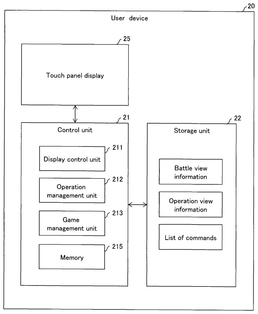
As illustrated inFIG. 1, a user device20stores a game application (that is, a program) therein.
The user device20is a game processing computer (information processing device such as a smartphone, for example) used by a user who plays games. The user device20includes a control unit21, which has a CPU, a RAM and a ROM, a storage unit22, and a touch panel display25.
The touch panel display25as an I/O unit functions as an output means and an input means for the user. Specifically, the user device20outputs information on the touch panel display25. The user can perform various icon operations depending on a touch state on the screen, such as an operation of touching the screen of the touch panel display25with a finger or another input tool (touch operation), an operation of releasing the finger from the screen (release operation), and an operation of sliding the finger on the screen while keeping touching the screen (swipe operation).
The control unit21executes the game application stored in the storage unit22thereby to function as a display control unit211, an operation management unit212, and a game management unit213.
The display control unit211controls a view on the screen of the touch panel display25.
The operation management unit212detects a touch state on the screen of the touch panel display25, and identifies the user-input contents.
The game management unit213manages a game progress of a one-on-one game. For the game progress, attacks from the attacking player who has a right to attack in a match to the defending player, winning/losing judgment, and the like are managed. The game management unit213holds data on an attack time limit by which the attacking player is changed.
As illustrated inFIG. 4A, according to the present embodiment, a game view500includes a battle display area510and an operation area520.
Player images511and512of the players who fight each other are displayed in the battle display area510. In the present embodiment, the player image511of the user and the player image512of the opponent are displayed. Herein, the opponent is not another user but a computer.
A plurality of polygonal icons521as two-dimensionally arranged graphic forms is displayed in the operation area520. In the present embodiment, the polygonal icons521are hexagons. Each polygonal icon521is arranged adjacent to other polygonal icons521. More specifically, the sides of each polygonal icon521oppose the corresponding sides of other adjacent polygonal icons521. For example, the polygonal icons521a,521band521care adjacent to six, three and two polygonal icons521, respectively. The user moves (swipes) with a single stroke a position touched by a finger or another input tool on the screen of the touch panel display25, thereby selecting a plurality of adjacent polygonal icons521along the input trajectory drawn with a single stroke. That is, the user performs a swipe operation on the screen of the touch panel display25thereby to select polygonal icons521depending on an input trajectory in the swipe operation.
Further, as illustrated inFIG. 4A, each polygonal icon521is provided with an information display area522, in which an identifier indicating an allocated key is displayed. When the user selects polygonal icons521via the swipe operation, a key sequence in which the keys (input keys) allocated to the selected polygonal icons521are linked is generated, and an attack command depending on the key sequence is selected.
As illustrated inFIG. 4B, in the present embodiment, each information display area522displays therein any of the arrow symbols indicating “up”, “down”, “left”, “right”, “upper right”, “upper left”, “lower right” and “lower left”, and the characters associated with attack types including “P (punch)” and “K (kick).” Any key identifiers capable of identifying each polygonal icon521may be employed, and colors may be employed in addition to symbols and characters.
The control unit21further includes a memory215for managing the progress of a game. The memory215holds key arrangement information, input trajectory information, and game progress information.
The key arrangement information includes data on key identifiers, arrangement positions, and keys.
The key identifier data area records therein data on identifiers for identifying polygonal icons521.
The arrangement position data area records therein data on arrangement positions (coordinates) of the polygonal icons521.
The key data area records therein data on keys allocated to the polygonal icons521.
The input trajectory information includes data on keys (input keys) allocated to the polygonal icons521selected in the operation area520in the game view500. In the present embodiment, a key sequence is generated in which one or more keys selected by an input trajectory drawn with a single stroke between user's touch on and release from the screen of the touch panel display25are sequentially recorded between the touch and the release. The key sequence may include only one single key.
The game progress information includes data on attack right setting and life point of each player. The game progress information is registered when the user starts a game, and is deleted when he/she terminates the game.
The player data area records therein data on an identifier for identifying a player (opponent) with whom the user plays a game. The present embodiment assumes that the user (first player) of the user device20plays a game with a computer (second player). In this case, the player data area for game progress information in the memory215records therein an identifier for identifying a “computer” as the opponent.
The attack right setting data area records therein a flag for identifying the attacking player out of the first and second players. In the present embodiment, the attacking player can attack the opponent (defending player).
The life point data area records therein data on elements (life point) for determining winning/losing of a one-on-one fighting game. In the present embodiment, the life point of the defending player decreases due to attacks. When the life point of the player earlier reaches a reference value (of “0”, for example) or less than the opponent, the player loses.
The storage unit22stores battle view information, operation view information, and a list of commands therein.
The battle view information includes information for defining player images and the like displayed in the battle display area510.
The operation view information includes information for defining polygonal icons521and the like displayed in the operation area520.
The list of commands includes information for defining execution key, attack ability, attack animation and the like for each attack command.
The attack command data area records therein data on identifiers for identifying types of attacks.
The execution key data area records therein data on keys (key sequences) required to execute attacks. For example, the key sequences such as “K”, “P”, “down→lower right right→P”, and “down→lower left→left→K” are recorded as the execution keys.
The attack ability data area records therein data on attack ability, that is, damages subjected to the defending player. Continuous attacks (“combo”), in which a plurality of attack commands is combined, may be executed in one input trajectory. When one attack command is combined with another attack command in the continuous attacks, an adjustment value for changing corresponding attack ability is recorded. For example, attack ability of an attack command increases depending on the adjustment value.
The attack animation data area records therein data on animations displayed in the battle display area510. The animations indicate the contents of attacks of the players.
The processes in the control unit21during a game will be described below. Herein, the description will be made in the order of an activation process (FIG. 2A), a tap process (FIG. 2B), an input operation process (FIG. 2C), a time limit management process (FIG. 2D) and an input completion process (FIG. 3).
Activation Process
The activation process will be first described with reference toFIGS. 2A and 5A to 5D. When playing a one-on-one fighting game, the user activates the game application in the user device20.
In this case, the control unit21in the user device20performs a game view display process (step S0-1). Specifically, the display control unit211in the control unit21outputs the game view500including the battle display area510and the operation area520on the screen of the touch panel display25.
The control unit21then performs a key output process (step S0-2). Specifically, the game management unit213in the control unit21randomly allocates a key to each polygonal icon521, and stores the allocated key in the memory215in association with the polygonal icon521. The display control unit211outputs an identifier indicating the key in the information display area522in each polygonal icon521.
In this case, as illustrated inFIG. 5A, the identifiers indicating the allocated keys are displayed in the information display areas522in the game view500, respectively.
Tap Process
The tap process (identifier changing process) will be described below with reference toFIGS. 2B and 4B. When changing a key, the player taps (performs the tap operation on) a polygonal icon521with a finger. That is, the user touches the screen of the touch panel display25with a finger, and releases the finger within a predetermined time without moving the finger from the touch position on the screen.
In this case, the control unit21performs a tap detection process (step S1-1). Specifically, when the display control unit211detects a user's touch at a first position on the screen of the touch panel display25, and detects release within a predetermined short time without any motion of the touch position from the first position, the user operation is determined as tap operation.
The control unit21then performs a key changing process (step S1-2). Specifically, the management unit213randomly re-allocates a key to the tapped polygonal icon521, and stores the allocated key in association with the tapped polygonal icon521in the memory215. The display control unit211outputs an identifier indicating the key into each information display area522.
In this case, as illustrated inFIG. 4B, each information display area522displays a randomly-changed key therein. Herein, the user can repeatedly perform the tap operation several times such as one tap or two taps until a desired key is displayed.
Input Operation Process
The input operation process will be described below with reference toFIGS. 2C and 5A to 5D. Herein, the user confirms an arrangement of the keys allocated to the polygonal icons521in the game view500displayed on the screen of the touch panel display25. The user searches execution keys (key sequence) corresponding to a predetermined attack command in the key arrangement. When finding execution keys, the user performs the touch operation on the first key in the execution keys on the screen of the touch panel display25.
When the touch operation is performed, the control unit21performs a touch detection process (step S2-1). Specifically, the operation management unit212in the control unit21detects a touch on the screen of the touch panel display25. The operation management unit212stores the key allocated to the touched polygonal icon521in the memory215.
The control unit21then performs a reduced display process (step S2-2). Specifically, the display control unit211displays the selected polygonal icons521to be reduced in their size at a predetermined rate. When the user returns the finger onto the previously-input trajectory without releasing the finger from the screen of the touch panel display25, that is, re-touches the previously-touched polygonal icon521, the display control unit211displays the re-touched polygonal icon521in the original size.
FIG. 5Billustrates a case in which the user selects with a single stroke three polygonal icons521, that is, the user selects three polygonal icons521from the touch operation to the release operation. At this time, the selected polygonal icons521on the input trajectory are displayed in a reduced size in the game view500.
The control unit21then performs a valid combination search process based on the input trajectory (step S2-3). Specifically, the display control unit211identifies a key sequence of the input keys stored in the memory215. The display control unit211searches an execution key matching with the head of the key sequence in the list of commands stored in the storage unit22.
The control unit21then performs a determination process as to whether the command can be completed (step S2-4). Specifically, when being able to detect an attack execution key matching with the head of the key sequence, the display control unit211identifies the next key missing in the execution key. Then, the display control unit211identifies all the polygonal icons521(peripheral graphic forms) adjacent to the final position (the last-selected polygonal icon521) in the input trajectory. The display control unit211identifies the keys (adjacent keys) allocated to the specified polygonal icons521. The display control unit211checks whether the adjacent keys include a key (next key) required to complete the execution key. When the adjacent keys include a next key, the display control unit211determines that the command can be completed. In contrast, when the adjacent keys do not include a next key, the display control unit211determines that the command cannot be completed.
When the display control unit211determines that the command cannot be completed (“NO” in step S2-4), the control unit21returns the control to the touch detection process (step S2-1).
In contrast, when the display control unit211determines that the command can be completed (“YES” in step S2-4), the control unit21performs a hint output process (step S2-5). Specifically, the operation management unit212displays a polygonal icon521allocated with the next key among the polygonal icons521adjacent to the last-selected polygonal icon521in an emphasizing manner (hint display). Thereby, the user can identify the polygonal icon521allocated with the next key.
FIG. 5Billustrates two possibilities in which the execution key can be completed by a key sequence of polygonal icons521in an input trajectory. More specifically, two of the polygonal icons521adjacent to the last-selected polygonal icon521are allocated with the “P” key. When “P” is selected as the next key for the key sequence of “down→lower right→right”, the execution key is completed. In this case, the polygonal icons521allocated with the next key are displayed in an emphasizing manner by double-line surrounding. The process returns to the touch detection process (step S2-1).
Time Limit Management Process
The time limit management process will be described below with reference toFIG. 2D.
Herein, the control unit21performs an attackable period countdown process (step S3-1). Specifically, the management unit213measures an elapsed time after the start of an attackable period of the attacking player.
The control unit21then performs a determination process as to whether the attackable period has ended (step S3-2). Specifically, the management unit213compares the elapsed time with the attack time limit. When the elapsed time reaches the attack time limit, the management unit213determines that the attackable period has ended.
When the elapsed time has not reached the attack time limit, the management unit213determines that the attackable period has not ended (“NO” in step S3-2). In this case, the control unit21continues the attack time limit countdown process (step S3-1).
In contrast, when the elapsed time reaches the attack time limit, the management unit213determines that the attackable period has ended (“YES” in step S3-2). In this case, the control unit21performs an attacking player changing process (step S3-3). Specifically, the management unit213transfers the right to attack to the opponent player in the game progress information recorded in the memory215so that the right to attack is set for the opponent player. In this case, the key output process (step S0-2) is performed again for the opponent.
Input Completion Process
The input completion process at the end of an input trajectory drawn with a single stroke will be described below with reference toFIGS. 3 and 5A to 5D. When completing inputting a desired key sequence, the user performs the release operation of releasing the finger from the touch panel display25.
In this case, the control unit21performs a release detection process (step S4-1). Specifically, the operation management unit212detects a release of the finger touching on the screen of the touch panel display25.
The control unit21then performs an input trajectory identifying process (step S4-2). Specifically, the management unit213identifies a key sequence of input keys based on the input trajectory information stored in the memory215.
The control unit21then performs a valid command search process depending on an input trajectory (step S4-3). Specifically, the management unit213searches an attack command corresponding to a key sequence in the list of commands in the storage unit22. In this case, the game management unit213first tries to identify an execution key of an attack command with the first key in the key sequence as the origin. When successfully identifying an execution key of one attack command, the game management unit213checks whether an additional execution key is included in the rest of the key sequence. The game management unit213identifies all the execution keys included in the key sequence configuring the input trajectory.
The control unit21then performs a determination process as to whether at least one attack command can be identified in the key sequence, that is, the key sequence includes a valid command (step S4-4). Specifically, the management unit213confirms whether at least one attack command can be identified in the key sequence. Wen successfully identifying at least one attack command in the key sequence, the management unit213determines that the key sequence includes a valid command.
When failing to identify an attack command in the key sequence, the management unit213determines that the key sequence does not include a valid command (“NO” in step S4-4). In this case, the control unit21terminates the input completion process.
In contrast, when the management unit213determines that the key sequence includes a valid command (“YES” in step S4-4), the control unit21repeatedly performs the following processes on the identified attack command (valid command).
At first, the control unit21performs an attack process (step S4-5). Specifically, the management unit213executes an attack command corresponding to the valid command. In this case, the display control unit211outputs an attack animation depending on an attack from the attacking player to the defending player in the battle display area510.
The control unit21then performs an opponent's life point update process (step S4-6). Specifically, the management unit213determines attack ability associated with a current attack command in the list of commands recorded in the storage unit22. Herein, when the current attack command is the second or subsequent attack command in the continuous attacks, the game management unit213determines an adjustment value associated with the current attack command in the list of commands, and changes (increases, for example) the attack ability by use of the adjustment value. The game management unit213determines life point of the defending player in the game progress information recorded in the memory215. The game management unit213calculates a value obtained by subtracting the attack ability from the life point of the defending player, and updates the life point of the defending player by use of the calculated value.
The control unit21then performs a determination process as to whether the match has ended (step S4-7). Specifically, the management unit213compares the life point of the defending player with a reference value (which is 0, herein). When the life point reaches the reference value or less, the management unit213determines that the match has ended.
When the management unit213determines that the match has ended (“YES” in step S4-7), the control unit21performs an attacking player winning process (step S4-8). Specifically, the management unit213determines the attacking player as a winner. In this case, the display control unit211outputs a winner animation in the image display area of the attacking player and a loser animation in the image display area of the defending player in the battle display area510.
In contrast, when the life point of the defending player remains, the management unit213determines that the match has not ended. In this case (“NO” in step S4-7), the control unit21repeatedly performs the processes in and subsequent to step S4-5on the remaining valid commands.
InFIG. 5C, it is assumed that two input trajectories TR1and TR2are detected from touch to release in the input trajectories including eight polygonal icons521. Herein, the key sequence of the input trajectory TR1is “down”→“lower right”→“right”→“P”, and the key sequence of the input trajectory TR2is “down”→“lower left”→“left”→“K”. In this case, the attack commands corresponding to the input trajectories TR1and TR2are executed as continuous attacks.
As illustrated inFIG. 5D, an attack on the player image512of the defending player is made from the player image511of the attacking player. Herein, an attack AT1based on the input trajectory TR1and an attack AT2based on the input trajectory TR2are sequentially made.
When terminating the process on all the valid commands, the control unit21performs a key re-output process (step S4-9). Specifically, the management unit213randomly allocates keys to the polygonal icons521on an input trajectory. The display control unit211outputs an identifier indicating an allocated key in the information display area522in each polygonal icon521, and terminates the input completion process.
Computer Match Process
An attack process when the opponent is a computer and the computer is the attacking player will be described. In this case, the management unit213searches an execution key of an attack command in the key arrangement allocated in the operation area520in the touch panel display25. An attack command is repeated from an execution key with the strongest attack ability within an attackable period. When the opponent is a computer and the computer is the attacking player, the keys are not permitted to change in the tap process by the user.
The above described embodiment achieves the following advantages.
(1) The player images511and512of the game players are displayed in the battle display area510. A plurality of polygonal icons521is displayed in the operation area520. Each polygonal icon521is arranged adjacent to other polygonal icons521. The sides of each polygonal icon521oppose the corresponding sides of other adjacent polygonal icons521. Accordingly, the user continuously selects a plurality of polygonal icons521with drawing motion with a single stroke thereby inputting a command in a key sequence.
(2) Each polygonal icon521is provided with the information display area522, in which an identifier indicating an allocated key is displayed. Thereby, the user can input a command by use of a combination of polygonal icons521with various information displayed therein. For example, the user can select various attacks by selecting a key subsequent to another key.
In addition, the control unit21performs the key changing process in the tap process (step S1-2). Thereby, the user can change the keys allocated to the polygonal icons521as desired, thereby facilitating a valid command in the key sequence to be established.
(3) The control unit21performs the reduced display process (step S2-2). Thereby, the user can identify an input trajectory. Further, when detecting a return of the finger on the input trajectory, that is, a retouch on a polygonal icon521, the display control unit211returns the retouched polygonal icon521to the original size. Thereby, the user can re-select a polygonal icon521.
(4) When the display control unit211determines that the command can be completed (“YES” in step S2-4), the control unit21performs the hint output process (step S2-5). Thereby, even when not knowing the execution key of an attack command well, the user can enjoy the game by use of hints.
(5) When the elapsed time reaches the attack time limit and the management unit213determines that the attackable period has ended (“YES” in step S3-2), the control unit21performs the attacking player changing process (step S3-3). Thereby, the user can enjoy the game with a feeling of speed in the time limit.
(6) When the management unit213determines that the key sequence includes a valid command (“YES” in step S4-4), the control unit21repeatedly performs the attack process (step S4-5) on the identified attack command (valid command). Thereby, the user can repeat continuous attacks as a combination of attacks by a single drawing action with a single stroke.
A second embodiment will be described below with reference toFIGS. 6C to 8D. In the first embodiment, the control unit21outputs a hint to a polygonal icon allocated with a key for which an attack command can be executed. In the second embodiment, the control unit21sets a non-displayed command (hidden command) in a polygonal icon. A detailed description of the similar parts will be omitted.
In the present embodiment, the user can select polygonal icons521with the same pattern or color, that is, with the same identifier, through a drawing action with a single stroke. Also in the second embodiment, the tap process and the time limit management process are performed, and the right to attack is transferred and set based on the attack time limit.
In the present embodiment, when the attacking player selects a polygonal icon521(hidden command graphic) set with a hidden command, unfavorable progress of the game (such as losing) against the attacking player is caused. A polygonal icon521set with a hidden command is displayed in the same form as the normal polygonal icons521. Therefore, the user cannot determine the presence of a hidden command in a polygonal icon521by appearance.
In the present embodiment, the key arrangement information further records a hidden cell flag and a hint cell flag in association with a key identifier.
The hidden cell flag is designed for identifying a polygonal icon521set with a hidden command.
The hint cell flag is designed for identifying a polygonal icon521(hint display graphic) displaying a hint for a hidden command. In the present embodiment, the polygonal icon521with a hint cell displays the number of polygonal icons521set with hidden commands (positional relationship information) among the polygonal icons521adjacent to the polygonal icon with a hint cell.
Similarly as inFIG. 4A, the game view500includes the battle display area510and the operation area520. A plurality of polygonal icons521is displayed in the operation area520. Each polygonal icon521is arranged adjacent to other polygonal icons521. More specifically, the sides of each polygonal icon521oppose the corresponding sides of its adjacent polygonal icons521. The user moves (swipes) the position touched by a finger or another input tool on the screen of the touch panel display25with a single stroke, thereby selecting a series of adjacent polygonal icons521along the input trajectory drawn with a single stroke. That is, the user can select the polygonal icons521depending on the input trajectory by the swipe operation on the screen of the touch panel display25.
Further, each polygonal icon521is provided with an information display area522displaying a hint therein. A hint is displayed in the information display area522in a polygonal icon521adjacent to the input trajectory. In the present embodiment, the number of polygonal icons521set with hidden commands among the polygonal icons521adjacent to the polygonal icon521with a hint is displayed.
The list of commands in the storage unit22according to the present embodiment includes attack ability functions for determining attack ability of attack commands. The attack ability functions calculate attack ability depending on attributes (pattern and color) and the number of keys allocated to the polygonal icons521, for example.
Activation Process
An activation process will be described with reference toFIGS. 6A and 8A to 8D. When playing a one-on-one fighting game, the user activates the game application in the user device20.
In this case, the control unit21performs a game view display process (step S5-1). Specifically, the display control unit211outputs the game view500including the battle display area510and the operation area520on the screen of the touch panel display25.
The control unit21then performs a hidden key setting process (step S5-2). Specifically, the management unit213allocates a hidden command to a randomly-selected polygonal icon521. The game management unit213records information on the polygonal icon521(hidden cell) set with a hidden cell flag in the key arrangement information in the memory215.
The control unit21then performs a key output process (step S5-3). Specifically, the management unit213randomly allocates a key (pattern and color) to each polygonal icon521. The display control unit211outputs an identifier indicating a key on the top of each polygonal icon521.
In this case, as illustrated inFIG. 8A, in the game view500, an identifier (pattern and color) indicating an allocated key is displayed in each polygonal icon521. There will be herein assumed a case in which a hidden command is allocated to a polygonal icon521s.
Input Operation Process
An input operation process will be described below with reference toFIGS. 6B and 8A to 8D. Herein, the user checks the arrangement of a key allocated to each polygonal icon521in the game view500displayed on the screen of the touch panel display25. The user searches an execution key (key sequence) corresponding to a predetermined attack command in the key arrangement. When finding an execution key, the user performs the touch operation on the screen of the touch panel display25.
When the touch operation is performed, the control unit21performs a touch detection process (step S6-1). Specifically, the operation management unit212detects a touch on the screen of the touch panel display25. The operation management unit212stores a key allocated to the touched polygonal icon521in the memory215.
The control unit21then performs a reduced display process (step S6-2). Specifically, the display control unit211displays the selected polygonal icons521reduced in their size at a predetermined rate.
FIG. 8Billustrates a case in which the user selects five polygonal icons521with a single stroke. In this case, in the game view500, the selected polygonal icons521on the input trajectory are reduced in their size to be displayed.
Hint Process
A hint process will be described with reference toFIG. 6C.
Herein, the control unit21performs a process of detecting a touch state on a hidden cell (step S7-1). Specifically, the management unit213identifies a polygonal icon521(hint cell) recording a hint cell flag therein in the key arrangement information in the memory215. The game management unit213calculates the number of polygonal icons521(hidden cells) set with hidden cell flags (the number of touched hidden cells) among the polygonal icons521adjacent to the hint cell.
The control unit21then performs a hidden cell touch state display process (step S7-2). Specifically, the display control unit211outputs the number of touched hidden cells calculated in the game management unit213to the information display area522in each polygonal icon521with a hint cell.
Input Completion Process
An input completion process will be described below with reference toFIGS. 7 and 8A to 8D. When completing inputting a desired key sequence, the user performs a release operation of releasing the finger from the touch panel display25.
In this case, the control unit21performs a release detection process similarly as in step S4-1.
The control unit21then performs an input trajectory identifying process similarly as in step S4-2.
The control unit21then performs a determination process as to whether a hidden key is present on an input trajectory (step S8-3). Specifically, the management unit213uses the key arrangement information recorded in the memory215to confirm whether a hidden cell flag is set in the selected polygonal icons521.
When the management unit213determines that a hidden key is present on the input trajectory (“YES” in step S8-3), the control unit21performs an attacking player defeat process (step S8-4). Specifically, the management unit213identifies the attacking player as a loser. In this case, the display control unit211outputs a loser animation in the image display area of the attacking player and a winner animation in the image display area of the defending player in the battle display area510.
In contrast, when the management unit213determines that a hidden key is not present on the input trajectory (“NO” in step S8-3), the control unit21performs a process of changing to a hint cell around the input trajectory (step S8-5). Specifically, the management unit213sets a hint cell flag to the polygonal icons521around the input trajectory in the key arrangement information.
InFIG. 8C, a hidden cell flag is set in polygonal icons521adjacent to the input trajectory in the game view500. With the hint process described above, a hint is displayed in the information display area522in the polygonal icon521set with a hint cell flag. Herein, since the polygonal icon521sis a hidden cell, “1” is displayed in the polygonal icons521adjacent thereto. In contrast, “0” is displayed in the polygonal icons521non-adjacent to the hidden cell.
The control unit21then performs an attack ability calculation process based on an input trajectory (step S8-6). Specifically, the management unit213calculates attack ability by use of an attack ability function recorded in the list of commands.
The control unit21then performs a cell erase process on an input trajectory (step S8-7). Specifically, the management unit213erases the polygonal icons521on an input trajectory in the operation area520.
The control unit21then performs an attack process (step S8-8). Specifically, the management unit213executes an attack command corresponding to a valid command specified in the list of commands. In this case, the display control unit211outputs an attack animation depending on an attack from the attacking player to the defending player in the battle display area510.
The control unit21then performs an opponent's life point update process similarly as in step S4-6(step S8-9).
The control unit21then performs a determination process as to whether the match has ended similarly as in step S4-7(step S8-10).
When the management unit213determines that the match has ended (“YES” in step S8-10), the control unit21performs an attacking player winning process similarly as in step S4-8(step S8-11).
When the management unit213determines that the match has not ended (“NO” in step S8-10), the control unit21performs a cell movement/addition process depending on an erased cell (step S8-12). Specifically, the display control unit211moves the remaining polygonal icons521to fill the spaces of the erased polygonal icons521on the input trajectory. Further, the display control unit211adds polygonal icons521to fill the empty cells. The game management unit213randomly allocates new keys to the added polygonal icons521. In this case, the polygonal icon521with a hint cell is subjected again to the hint process.
InFIG. 8D, the polygonal icons521are erased on the input trajectory, and upper polygonal icons521are moved downward. Further, new polygonal icons521are inserted at the upper end of the operation area520. Also in this case, the newly-inserted polygonal icons521are randomly set with hidden keys in the hidden key setting process (step S5-2). A hint is displayed depending on the number of neighboring touched hidden cells in the polygonal icons521recording hint cell flags therein.
According to the second embodiment, the following advantages are obtained in addition to the advantages of the first embodiment.
(7) The control unit21performs the hidden key setting process (step S5-2). This allows the user to enjoy the game by use of the setting other than the keys allocated on the screen of the touch panel display25.
(8) The control unit21performs the process of detecting a touch state on a hidden cell (step S7-1). The control unit21performs the hidden cell touch state display process (step S7-2). This allows the user to select an attack command while predicting the position of a hidden key by use of a hint.
The above described embodiments may be modified as follows.In the first and second embodiments, a plurality of polygonal icons521is displayed in the operation area520. The shape of icons to be subjected to trajectory input is not limited to polygonal. Any shapes capable of continuously selecting and identifying a trajectory with drawing motion on adjacent icons with a single stroke may be employed, such as circular shape, and characters or symbols allocated to keys.In the first and second embodiments, the opponent of the user is a computer. Instead, the user may play a game with another user. In this case, a management server for managing social network games is accessed. In this case, the management server identifies two users who play a game, and performs the input operation process and the input completion process.In the first and second embodiments, the right to attack is transferred and set based on an attack time limit in the time limit management process. Instead, the right to attack may be transferred and set per input completion process. In this case, when terminating the input completion process, the control unit21transfers and sets the right to attack to the other party.
Further, the attack time limit may be changed depending on capabilities of the players. In this case, the capabilities of the players are determined depending on user's skills or use frequencies (user attributes). Specifically, the storage unit22stores user attribute information on skills and use frequencies. Further, the game management unit213stores time limit calculation information for determining the attack time limit based on skills and use frequencies. The game management unit213determines the attack time limit by use of the time limit calculation information.
Moreover, when the opponent is a computer, the right to attack may be transferred and set depending on not the attack time limit but the number of attack limitations. In this case, the game management unit213counts the number of terminations of the input completion process. When the number of terminations reaches a predetermined number of times, the game management unit213transfers and sets the right to attack to the other party.In the first and second embodiments, an attack command is identified based on the keys allocated to the selected polygonal icons521on an input trajectory. Additionally, the attack contents may be changed by the shape (gesture) of the input trajectory. In this case, the storage unit22records correction functions for adjusting the attack ability in association with input trajectory patterns. For example, when the input trajectory is a straight line shape, a correction function for increasing the attack ability is employed. The attack ability is adjusted based on a correction function depending on a shape of the input trajectory.In the first and second embodiments, a symbol, character or color is displayed as an identifier indicating a key in a polygonal icon521. The identifiers of the keys displayed in polygonal icons521are not limited thereto. In this case, combinations of keys displayed in the polygonal icons521are recorded as execution keys in the list of commands. A predetermined word (such as magic spell or actual word) may be used in a key sequence on an input trajectory. In this case, attributes (category or difficulty level) of a magic spell or actual word are identified, and the attack ability is calculated based on the attributes. When a combination of keys in the input trajectory matches with the execution key, the attack command is executed.In the first and second embodiments, the control unit21performs the key changing process by the tap process (step S1-2). In the key changing process, keys to be allocated are randomly changed. Instead, the keys may be changed in a predetermined order. In this case, a key output order (“up”→“upper right”→“right”→“lower right”→“down”→ . . . →“K (kick)”, for example) is previously determined. Thereby, the user can change the keys in consideration of the rule.
When a key is changed in the tap process, penalties (unfavorable conditions for match) may be provided. In this case, the game management unit213stores therein penalty information for determining a penalty. The penalties may include decrease in attack ability of a valid command, increase in damages by opponent (decrease in life point), reduction in attack time limit, and the like. The game management unit213determines a penalty depending on the number of taps, and makes the match in consideration of the penalty. Thereby, the user can play the game in consideration of easily established valid command by the tap process, and disadvantages thereof.In the first embodiment, when determining that a command can be completed (“YES” in step S2-4), the control unit21performs the hint output process (step S2-5). Herein, a polygonal icon521in which a key required to complete an execution key is displayed is emphasized for display to be identifiable. The hint display method is not limited thereto. For example, the attack commands recorded in the list of commands may be displayed in association with the polygonal icons521.
FIG. 9is a more detailed block diagram illustrating an exemplary user device20according to certain embodiments of the present disclosure. In certain embodiments, user device20may be a smartphone. However, the skilled artisan will appreciate that the features described herein may be adapted to be implemented on other devices (e.g., a laptop, a tablet, a server, an e-reader, a camera, a navigation device, etc.). The exemplary user device20ofFIG. 9includes a controller110and a wireless communication processor102connected to an antenna101. A speaker104and a microphone105are connected to a voice processor103.
The controller110is an example of the control unit21shown inFIG. 1and may include one or more Central Processing Units (CPUs), and may control each element in the user device20to perform functions related to communication control, audio signal processing, control for the audio signal processing, still and moving image processing and control, and other kinds of signal processing. The controller110may perform these functions by executing instructions stored in a memory150. Alternatively or in addition to the local storage of the memory150, the functions may be executed using instructions stored on an external device accessed on a network or on a non-transitory computer readable medium. As described above in relation toFIG. 1, the controller110may execute instructions allowing the controller110to function as the display control unit211, operation management unit212and game management unit213depicted inFIG. 1.
The memory150is an example of the storage unit22shown inFIG. 1and includes but is not limited to Read Only Memory (ROM), Random Access Memory (RAM), or a memory array including a combination of volatile and non-volatile memory units. The memory150may be utilized as working memory by the controller110while executing the processes and algorithms of the present disclosure. Additionally, the memory150may be used for long-term storage, e.g., of image data and information related thereto. As disclosed in relation toFIG. 1, the memory150may be configured to store the battle view information, operation view information and list of commands.
The user device20includes a control line CL and data line DL as internal communication bus lines. Control data to/from the controller110may be transmitted through the control line CL. The data line DL may be used for transmission of voice data, display data, etc.
The antenna101transmits/receives electromagnetic wave signals between base stations for performing radio-based communication, such as the various forms of cellular telephone communication. The wireless communication processor102controls the communication performed between the user device20and other external devices via the antenna101. For example, the wireless communication processor102may control communication between base stations for cellular phone communication.
The speaker104emits an audio signal corresponding to audio data supplied from the voice processor103. The microphone105detects surrounding audio and converts the detected audio into an audio signal. The audio signal may then be output to the voice processor103for further processing. The voice processor103demodulates and/or decodes the audio data read from the memory150or audio data received by the wireless communication processor102and/or a short-distance wireless communication processor107. Additionally, the voice processor103may decode audio signals obtained by the microphone105.
The exemplary user device20may also include a display120, a touch panel130, an operation key140, and a short-distance communication processor107connected to an antenna106. The display120may be a Liquid Crystal Display (LCD), an organic electroluminescence display panel, or another display screen technology. In addition to displaying still and moving image data, the display120may display operational inputs, such as numbers or icons which may be used for control of the user device20. The display120may additionally display a GUI for a user to control aspects of the user device20and/or other devices. Further, the display120may display characters and images received by the user device20and/or stored in the memory150or accessed from an external device on a network. For example, the user device20may access a network such as the Internet and display text and/or images transmitted from a Web server.
The touch panel130may include a physical touch panel display screen and a touch panel driver. The touch panel130may include one or more touch sensors for detecting an input operation on an operation surface of the touch panel display screen. The touch panel130also detects a touch shape and a touch area. Used herein, the phrase “touch operation” refers to an input operation performed by touching an operation surface of the touch panel display with an instruction object, such as a finger, thumb, or stylus-type instrument. In the case where a stylus or the like is used in a touch operation, the stylus may include a conductive material at least at the tip of the stylus such that the sensors included in the touch panel130may detect when the stylus approaches/contacts the operation surface of the touch panel display (similar to the case in which a finger is used for the touch operation).
One or more of the display120and the touch panel130are examples of the touch panel display25depicted inFIG. 1and described above.
In certain aspects of the present disclosure, the touch panel130may be disposed adjacent to the display120(e.g., laminated) or may be formed integrally with the display120. For simplicity, the present disclosure assumes the touch panel130is formed integrally with the display120and therefore, examples discussed herein may describe touch operations being performed on the surface of the display120rather than the touch panel130. However, the skilled artisan will appreciate that this is not limiting.
For simplicity, the present disclosure assumes the touch panel130is a capacitance-type touch panel technology. However, it should be appreciated that aspects of the present disclosure may easily be applied to other touch panel types (e.g., resistance-type touch panels) with alternate structures. In certain aspects of the present disclosure, the touch panel130may include transparent electrode touch sensors arranged in the X-Y direction on the surface of transparent sensor glass.
The touch panel driver may be included in the touch panel130for control processing related to the touch panel130, such as scanning control. For example, the touch panel driver may scan each sensor in an electrostatic capacitance transparent electrode pattern in the X-direction and Y-direction and detect the electrostatic capacitance value of each sensor to determine when a touch operation is performed. The touch panel driver may output a coordinate and corresponding electrostatic capacitance value for each sensor. The touch panel driver may also output a sensor identifier that may be mapped to a coordinate on the touch panel display screen. Additionally, the touch panel driver and touch panel sensors may detect when an instruction object, such as a finger is within a predetermined distance from an operation surface of the touch panel display screen. That is, the instruction object does not necessarily need to directly contact the operation surface of the touch panel display screen for touch sensors to detect the instruction object and perform processing described herein. For example, in certain embodiments, the touch panel130may detect a position of a user's finger around an edge of the display panel120(e.g., gripping a protective case that surrounds the display/touch panel). Signals may be transmitted by the touch panel driver, e.g. in response to a detection of a touch operation, in response to a query from another element based on timed data exchange, etc.
The touch panel130and the display120may be surrounded by a protective casing, which may also enclose the other elements included in the user device20. In certain embodiments, a position of the user's fingers on the protective casing (but not directly on the surface of the display120) may be detected by the touch panel130sensors. Accordingly, the controller110may perform display control processing described herein based on the detected position of the user's fingers gripping the casing. For example, an element in an interface may be moved to a new location within the interface (e.g., closer to one or more of the fingers) based on the detected finger position.
Further, in certain embodiments, the controller110may be configured to detect which hand is holding the user device20, based on the detected finger position. For example, the touch panel130sensors may detect a plurality of fingers on the left side of the user device20(e.g., on an edge of the display120or on the protective casing), and detect a single finger on the right side of the user device20. In this exemplary scenario, the controller110may determine that the user is holding the user device20with his/her right hand because the detected grip pattern corresponds to an expected pattern when the user device20is held only with the right hand.
The operation key140may include one or more buttons or similar external control elements, which may generate an operation signal based on a detected input by the user. In addition to outputs from the touch panel130, these operation signals may be supplied to the controller110for performing related processing and control. In certain aspects of the present disclosure, the processing and/or functions associated with external buttons and the like may be performed by the controller110in response to an input operation on the touch panel130display screen rather than the external button, key, etc. In this way, external buttons on the user device20may be eliminated in lieu of performing inputs via touch operations, thereby improving water-tightness.
The antenna106may transmit/receive electromagnetic wave signals to/from other external apparatuses, and the short-distance wireless communication processor107may control the wireless communication performed between the other external apparatuses. Bluetooth, IEEE 802.11, and near-field communication (NFC) are non-limiting examples of wireless communication protocols that may be used for inter-device communication via the short-distance wireless communication processor107.
The user device20may include a motion sensor108. The motion sensor108may detect features of motion (i.e., one or more movements) of the user device20. For example, the motion sensor108may include an accelerometer to detect acceleration, a gyroscope to detect angular velocity, a geomagnetic sensor to detect direction, a geo-location sensor to detect location, etc., or a combination thereof to detect motion of the user device20. In certain embodiments, the motion sensor108may generate a detection signal that includes data representing the detected motion. For example, the motion sensor108may determine a number of distinct movements in a motion (e.g., from start of the series of movements to the stop, within a predetermined time interval, etc.), a number of physical shocks on the user device20(e.g., a jarring, hitting, etc., of the electronic device), a speed and/or acceleration of the motion (instantaneous and/or temporal), or other motion features. The detected motion features may be included in the generated detection signal. The detection signal may be transmitted, e.g., to the controller110, whereby further processing may be performed based on data included in the detection signal. The motion sensor108can work in conjunction with a Global Positioning System (GPS) section160. The GPS section160detects the present position of the terminal device100. The information of the present position detected by the GPS section160is transmitted to the controller110. An antenna161is connected to the GPS section160for receiving and transmitting signals to and from a GPS satellite.
The user device20may include a camera section109, which includes a lens and shutter for capturing photographs of the surroundings around the user device20. In an embodiment, the camera section109captures surroundings of an opposite side of the user device20from the user. The images of the captured photographs can be displayed on the display panel120. A memory section saves the captured photographs. The memory section may reside within the camera section109or it may be part of the memory150. The camera section109can be a separate feature attached to the user device20or it can be a built-in camera feature.
Claims
- A system for providing a one-on-one game, the system comprising: a user interface including a touch panel display;and circuitry configured to control the touch panel display to display a plurality of graphic forms each indicating an identifier;identify a trajectory of a continuously drawn input on the touch panel display that selects a plurality of the graphic forms;identify the identifiers of the graphic forms corresponding to the input trajectory;identify at least a first command based on an arrangement of the identifiers when detecting an end of the input;and control a game operation of attacking an opponent based on the command.
- The system of claim 1 , wherein the circuitry is configured to control a game operation of performing continuous attacks based on a plurality of commands when a plurality of commands are identified based on the input trajectory.
- The system of claim 1 , wherein the circuitry is configured to: identify identifiers of graphic forms neighboring a graphic form corresponding to and end of the input;and display a hint as a candidate for selecting a neighboring graphic form to be a command based on the identifying.
- The system of claim 1 , wherein the circuitry is configured to control the touch panel display to apply a predetermined graphical effect to graphic forms along the input trajectory to differentiate the graphical forms along the input trajectory from other of the plurality of graphic forms.
- The system of claim 1 , wherein the circuitry is configured to control the touch panel display to change the identifiers of the selected graphic forms.
- The system of claim 1 , wherein the circuitry is configured to execute a hidden command when the selected graphic forms include a hidden command graphic form corresponding to the hidden command.
- The system of claim 6 , wherein the circuitry is configured to: identify graphic forms neighboring a selected graphic form as hint display graphic forms;calculate positional relationship information of the hint display graphic forms in relation to the hidden command graphic form;and display information corresponding to the positional relationship information on the hint display graphic forms.
- The system of claim 7 , wherein the circuitry is configured to: delete graphic forms that have been used for an attack and deploy new graphic forms before the input ends;and re-calculate positional relationship information of the hint display graphic forms in relation to the hidden command graphic form.
- The system of claim 1 , wherein the circuitry is configured to control the touch panel display to changing the identifiers of the graphic forms when detecting an operation for selecting graphic forms.
- The system of claim 9 , wherein the circuitry is configured to set unfavorable conditions for a match with the opponent after performing the identifier changing process.
- A non-transitory computer-readable recording medium including a program, which when executed by a system comprising circuitry and a user interface including a touch panel display, causes circuitry of the system to: control the touch panel display to display a plurality of graphic forms each indicating an identifier;identify a trajectory of a continuously drawn input on the touch panel display that selects a plurality of the graphic forms;identify the identifiers of the graphic forms corresponding to the input trajectory;identify at least a first command based on an arrangement of the identifiers when detecting an end of the input;and control a game operation of attacking an opponent based on the command.
- The non-transitory computer-readable recording medium of claim 11 , the program further causing the circuitry of the system to: perform continuous attacks based on a plurality of commands when a plurality of commands are identified based on the input trajectory.
- The non-transitory computer-readable recording medium of claim 11 , the program further causing the circuitry of the system to: identify the identifiers of graphic forms neighboring a graphic form corresponding to an end of the input;and control the touch panel display to display a hint as a candidate for selecting a neighboring graphic form to be a command based on the identifying.
- The non-transitory computer-readable recording medium of claim 11 , the program further causing the circuitry of the system to: apply a predetermined graphical effect to graphic forms along the input trajectory to differentiate the graphical forms along the input trajectory from other of the plurality of graphic forms.
- The non-transitory computer-readable recording medium of claim 11 , the program further causing the circuitry of the system to: control the touch panel display to change the identifiers of the selected graphic forms.
- The non-transitory computer-readable recording medium of claim 11 , the program further causing the circuitry of the system to: execute a hidden command when the selected graphic forms include a hidden command graphic form corresponding to the hidden command.
- The non-transitory computer-readable recording medium of claim 16 , the program further causing the circuitry of the system to: identify graphic forms neighboring a selected graphic form as hint display graphic forms;calculate positional relationship information of the hint display graphic forms in relation to the hidden command graphic form;and display information corresponding to the positional relationship information on the hint display graphic forms.
- The non-transitory computer-readable recording medium of claim 17 , the program further causing the circuitry of the system to: delete graphic forms that have been used for an attack and deploy new graphic forms before the input ends;and re-calculate positional relationship information of the hint display graphic forms in relation to the hidden command graphic form.
- The non-transitory computer-readable recording medium of claim 11 , the program further causing the circuitry of the system to: control the touch panel display to changing the identifiers of the graphic forms when detecting an operation for selecting graphic forms.
- The non-transitory computer-readable recording medium of claim 19 , the program further causing the circuitry of the system to: set unfavorable conditions for a match with the opponent after performing the identifier changing process.
- A game processing method performed by a system comprising a user interface including a touch panel display, the method comprising: controlling, by circuitry of the system, the touch panel display to display a plurality of graphic forms each indicating an identifier;identifying, by the circuitry, a trajectory of a continuously drawn input on the touch panel display that selects a plurality of the graphic forms;identifying, by the circuitry, the identifiers of the graphic forms corresponding to the input trajectory;identifying, by the circuitry, at least a first command based on an arrangement of the identifiers when detecting an end of the input;and controlling a game operation of attacking an opponent based on the command.
- The game processing method of claim 21 , further comprising: performing, by the circuitry, continuous attacks based on a plurality of commands when a plurality of commands are identified based on the input trajectory.
- The game processing method of claim 21 , further comprising: identifying, by the circuitry, the identifiers of graphic forms neighboring a graphic form corresponding to an end of the input;and controlling, by the circuitry, the touch panel display to display a hint as a candidate for selecting a neighboring graphic form to be a command based on the identifying.
- The game processing method of claim 21 , further comprising: applying, by the circuitry, a predetermined graphical effect to graphic forms along the input trajectory to differentiate the graphical forms along the input trajectory from other of the plurality of graphic forms.
- The game processing method of claim 21 , further comprising: controlling, by the circuitry, the touch panel display to change the identifiers of the selected graphic forms.
- The game processing method of claim 21 , further comprising: executing, by the circuitry, a hidden command when the selected graphic forms include a hidden command graphic form corresponding to the hidden command.
- The game processing method of claim 26 , further comprising: identifying, by the circuitry, graphic forms neighboring a selected graphic form as hint display graphic forms;calculating, by the circuitry, positional relationship information of the hint display graphic forms in relation to the hidden command graphic form;and displaying, by the touch panel display, information corresponding to the positional relationship information on the hint display graphic forms.
- The game processing method of claim 27 , further comprising: deleting, by the circuitry, graphic forms that have been used for an attack and deploy new graphic forms before the input ends;and re-calculating, by the circuitry, positional relationship information of the hint display graphic forms in relation to the hidden command graphic form.
- The game processing method of claim 21 , further comprising: controlling, by the circuitry, the touch panel display to change the identifiers of the graphic forms when detecting an operation for selecting graphic forms.
- The game processing method of claim 29 , further comprising: setting, by the circuitry, unfavorable conditions for a match with the opponent after performing the identifier changing process.
Disclaimer: Data collected from the USPTO and may be malformed, incomplete, and/or otherwise inaccurate.