U.S. Pat. No. 9,952,679
METHOD OF GIVING A MOVEMENT INSTRUCTION TO AN OBJECT IN A VIRTUAL SPACE, AND PROGRAM THEREFOR
AssigneeCOLOPL, INC.
Issue DateOctober 11, 2016
Illustrative Figure
Abstract
To give various movement instructions by body gestures to an object in a virtual space, a method includes detecting movements of controllers held by both hands of a user. The method further includes determining a first movement instruction based on the movements of the controllers. The method further includes causing a first character gazed at by the user to perform a first movement and causing a second character not gazed at by the user to perform a second movement depending on the first movement instruction. With this, instructions are given to the characters in the virtual space by means of body gestures.
Description
DETAILED DESCRIPTION First, at least one embodiment is described with reference to a list of contents thereof. A method of controlling an HMD and a program according to at least one embodiment includes the following configurations. (Item 1) A method of moving a character in a virtual space displayed on a head-mounted display mounted on a head of a user. The method includes detecting a movement of a controller. The method further includes determining a first movement instruction based on the movement of the controller. The method further includes causing a first character gazed at by a user to perform a first movement and causing a second character not gazed at by the user to perform a second movement depending on the first movement instruction. (Item 2) A method of moving a character in a virtual space displayed on a head-mounted display. The method includes acquiring a movement of a controller. The method further includes determining a first movement instruction based on the movement of the controller. The method further includes causing a character existing within a field-of-view region of the user to perform a first movement and causing a third character existing outside of the field-of-view region of a user to perform a third movement depending on the first movement instruction. (Item 3) A method according to Item 2, in which the character existing within the field-of-view region of the user includes a first character gazed at by the user and a second character not gazed at by the user. The method further includes causing the first character to perform the first movement and causing the second character to perform a second movement depending on the first movement instruction. (Item 4) A method according to Item 3, the method further including determining a second movement instruction different from the ...
DETAILED DESCRIPTION
First, at least one embodiment is described with reference to a list of contents thereof. A method of controlling an HMD and a program according to at least one embodiment includes the following configurations.
(Item 1)
A method of moving a character in a virtual space displayed on a head-mounted display mounted on a head of a user. The method includes
detecting a movement of a controller. The method further includes
determining a first movement instruction based on the movement of the controller. The method further includes
causing a first character gazed at by a user to perform a first movement and causing a second character not gazed at by the user to perform a second movement depending on the first movement instruction.
(Item 2)
A method of moving a character in a virtual space displayed on a head-mounted display. The method includes
acquiring a movement of a controller. The method further includes
determining a first movement instruction based on the movement of the controller. The method further includes
causing a character existing within a field-of-view region of the user to perform a first movement and causing a third character existing outside of the field-of-view region of a user to perform a third movement depending on the first movement instruction.
(Item 3)
A method according to Item 2,
in which the character existing within the field-of-view region of the user includes a first character gazed at by the user and a second character not gazed at by the user. The method further includes causing the first character to perform the first movement and causing the second character to perform a second movement depending on the first movement instruction.
(Item 4)
A method according to Item 3, the method further including
determining a second movement instruction different from the first movement instruction based on the movement of the controller. The method further includes causing a fourth character existing within the field-of-view region of the user to perform a fourth movement and causing a fifth character existing outside of the field-of-view region of the user to perform a fifth movement depending on the second movement instruction.
(Item 5)
A method according to Item 4, in which each of the first character, the second character, and the third character has a first attribute, in which each of the fourth character and the fifth character has a second attribute, and in which the first attribute differs from the second attribute.
(Item 6)
A method according to Item 3, wherein the method further includes varying the first movement, the second movement, and the third movement depending on a type of the first movement instruction.
(Item 7)
A method according to Item 4, wherein the method further includes varying the fourth movement and the fifth movement depending on a type of the second movement instruction.
(Item 8)
A method according to Item 1 or 3, in which the second movement includes the first movement performed after an elapse of a predetermined period from reception of the first movement instruction.
(Item 9)
A method according to Item 2, in which the third movement includes the first movement performed at a predetermined probability after an elapse of a predetermined period from reception of the first movement instruction.
(Item 10)
A method according to Item 4, in which the fifth movement includes the fourth movement performed after an elapse of a predetermined period from reception of the second movement instruction.
(Item 11)
A method according to Item 1 or 2, in which the movement of the controller includes movements of two controllers held by a right hand and a left hand of the user.
(Item 12)
A program for causing a computer to execute the method of any one of Items 1 to 11.
(Item 13)
A program according to Item 12, in which the program relates to a soccer game.
[Details of at Least One Embodiment]
Specific examples of a program for controlling a head-mounted display system according to at least one embodiment are described below with reference to the drawings. The present disclosure is not limited to those examples, and is defined by the scope of claims. It is intended to include all modifications within the scope of claims and the equivalents thereof. In the following description, like elements are denoted by like reference symbols in the description of the drawings, and redundant description thereof is omitted.
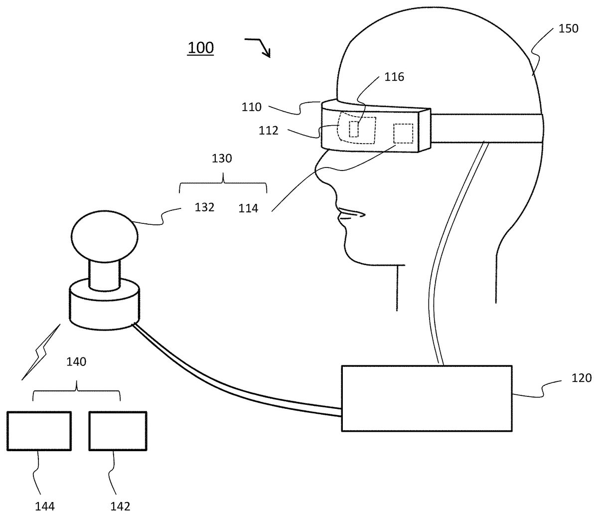
FIG. 1is an illustration of an HMD system100including an HMD110according to at least one embodiment. The HMD system100includes the HMD110to be worn on the head of a user150, a control circuit unit120, a tracking sensor132, and a controller140. Now, components constructing the HMD system100, specifically, the HMD110, the control circuit unit120, the tracking sensor132, and the controller140are described in detail with reference toFIG. 1toFIG. 3.
The HMD110includes a display112, which is a non-transmissive display device, a sensor unit114, and an eye gaze sensor116. In some embodiments, the display device is a partially transmissive display device. With a right-eye image and a left-eye image displayed on the display112, a three-dimensional image is provided as a virtual space through binocular parallax. The display112is arranged in front of the user's eyes, and thus the user can be immersed in the virtual space. The virtual space includes a background, various objects that can be operated by the user, menu images, and the like.
The display112may include a right-eye sub-display configured to provide a right-eye image, and a left-eye sub-display configured to provide a left-eye image. Further, as long as the right-eye image and the left-eye image can be provided, the display112may be constructed of one display device. For example, a shutter configured to enable recognition of a display image with only one eye may be switched at high speed, to thereby independently provide the right-eye image and the left-eye image.
The HMD110may further include the sensor unit114configured to detect the direction of the head of the user150wearing the HMD (for example, a magnetic sensor, an angular velocity sensor, or an acceleration sensor, or a combination thereof). The detected direction of the head of the user150may be used for changing the display image of the display112so as to follow the movement of the head of the user150when the head moves. With this, the user150can experience a further enhanced sense of immersion into a virtual reality space. Further, the sensor unit114may include a plurality of light sources. The light source is, for example, an LED configured to emit an infrared ray. The infrared ray emitted from the light source is detected as a detection point of the HMD110by the tracking sensor132.
The HMD110may further include the eye gaze sensor116having an eye tracking function of detecting gaze directions of the user's right and left eyes. In at least one embodiment, the eye gaze sensor116includes a right-eye sensor and a left-eye sensor, which are respectively configured to detect the gaze directions of the right and left eyes, to thereby detect a line-of-sight direction in which the user focuses his/her gaze. The eye gaze sensor116can employ a known sensor having an eye tracking function. For example, infrared light may be radiated to each of the right eye and the left eye to acquire reflection light from the cornea or the iris, to thereby obtain a rotational angle of the eyeball.
The eye gaze sensor116is configured to detect the gaze directions of the user's right and left eyes, to thereby specify a point of gaze being an intersection of both directions. The point of gaze specified when the user is looking at a near place is closer to the user than the point of gaze specified when the user is looking at a far place. When the point of gaze is specified, the user's line-of-sight direction is specified. The line-of-sight direction is a direction in which the user's line of sight is actually directed with both eyes. The line-of-sight direction is defined as, for example, a direction in which a straight line, which passes through a midpoint of the user's right and left eyes and the point of gaze, extends.
[Control Circuit Unit120]
The control circuit unit120is a computer to be connected to the HMD110. As illustrated inFIG. 2, the control circuit unit120includes a processing circuit202, a memory204, an input/output interface206, and a communication interface208, which are connected to each other via a bus serving as a data transmission path.
The processing circuit202includes various processing circuits such as a central processing unit (CPU), a micro-processing unit (MPU), and a graphics processing unit (GPU), and has a function of controlling the entire control circuit unit120and HMD system100.
The memory204includes a read only memory (ROM), a random access memory (RAM), and the like, and is configured to at least temporarily store control data, e.g., programs and calculation parameters to be used in the processing circuit. The memory204may include non-volatile storage devices such as a flash memory and a hard disc drive (HDD). In this case, the memory204stores data relating to various images and objects, a simulation program, and a user authentication program, and may further construct a database including a table for managing various items of data.
The input/output interface206includes various wire connection terminals such as a universal serial bus (USB) terminal, a digital visual interface (DVI) terminal, and a high-definition multimedia interface (HDMI) (trademark) terminal, and various processing circuits for wireless connection. The input/output interface206is configured to connect the HMD110, the tracking sensor132, and the controller140to each other.
The communication interface208includes various wire connection terminals for communicating to/from an external device via a network NW, and various processing circuits for wireless connection. The communication interface208is configured to adapt to various communication standards or protocols for communication via a local area network (LAN) or the Internet.
The control circuit unit120is configured to execute a predetermined application stored in the memory, to thereby present a virtual space on the display112. Further, the memory stores a program for operating various objects to be displayed in the virtual space, or for displaying and controlling various menu images and the like. The control circuit unit120is not required to be mounted on the HMD110, and may be constructed as separate hardware (for example, a known personal computer, or a server computer via a network). Further, only a part of the functions of the control circuit unit120may be mounted on the HMD110, and the remaining functions thereof may be part of separate hardware.
[Controller140]
The controller140is a device to be used by the user150so as to control the movement of the object in the virtual space. In at least one embodiment, the virtual space is a computer game.FIG. 3is a view for illustrating an example of an external shape of the controller140. An exemplary description of controller140is given below with reference toFIG. 3. The controller140includes a right-hand controller142to be used by the user150in his/her right hand, and a left-hand controller144to be used by the user150in his/her left hand. The right-hand controller142and the left-hand controller144are constructed as separate devices. Therefore, the user150can freely move the right hand holding the right-hand controller142and the left hand holding the left-hand controller144relative to each other. Each of the right-hand controller142and the left-hand controller144includes operation buttons302a-302j, collectively referred to as operation buttons302, infrared light emitting diodes (LEDs)304, a sensor306, and a transceiver308. As described later, in at least one embodiment only one of the sensor306or the infrared LEDs304is provided.
The right-hand controller142and the left-hand controller144respectively include frames326and336forming semicircular rings, which extend in a direction opposite to top surfaces (322and332) from both side surfaces of grips (324and334). On the outer surfaces of the respective frames326and336, a plurality of infrared LEDs304is located. In at least one embodiment, infrared LEDs304are buried in frames326and336. For example, a plurality of (for example, about 10) infrared LEDs304are arrayed in one row along a circumferential direction of each of the frames326and336. In at least one embodiment, a plurality of rows (for example, 2 rows) of infrared LEDs304is arrayed along the circumferential direction of each of the frames326and336. When the user150grips the controller140, the fingers of the user150other than the thumb are positioned between the grip (324or334) and the frame (326or336). Therefore, the infrared LEDs304arranged on the outer surface of each of the frames326and336are not hidden by being covered with the hand or the fingers of the user150. The infrared LEDs304may be further buried in a part of the surface of each of the grips324and334that is not hidden by the fingers of the user150in addition to the outer surface of each of the frames326and336. Infrared LEDs304are configured to emit infrared light during manipulations of the virtual space, such as playing of a computer game. The infrared light emitted from the infrared LEDs304can be used for detecting the position, the posture (inclination and direction), the speed, and the acceleration of each of the right-hand controller142and the left-hand controller144.
In order to enable detection of the position and the posture of each of the controllers142and144, each of the right-hand controller142and the left-hand controller144further includes the sensor306instead of or in addition to the infrared LEDs304. The sensor306may be, for example, a magnetic sensor, an angular velocity sensor, or an acceleration sensor, or a combination thereof. The sensor306is configured to output a value (magnetic, angular velocity, or acceleration value) corresponding to the direction and the movement of each of the controllers142and144when the user150moves each of the controllers142and144in his/her right and left hands. The value output from the sensor306is processed by an appropriate method, to thereby detect the position, the posture, the speed, and the acceleration of each of the right-hand controller142and the left-hand controller144.
In this manner, according to at least one embodiment, the controller140detects the motion of a portion of the user150's body. Specifically, the right-hand controller142detects the motion of the user's right hand, and the left-hand controller144detects the motion of the user's left hand. Thus, the motion of a non-head portion of the user's body is detected, allowing the movement of an object in the virtual space to be controlled based on a gesture of the user as described later. The method of detecting a non-head portion of the user's body is not limited to one using the controller140including a sensor mounted on the portion of the body, and image recognition besides any other physical and optical techniques are applicable. For example, a non-head portion of the user's body is detectable by using an external camera to locate a portion of the user's body and to continuously locate the portion of the user's body. Detailed description is given below of the detection of a non-head portion of the user's body by using the controller140.
[Tracking Sensor132]
The tracking sensor132is, for example, an infrared sensor, and is configured to detect the infrared ray from the light source of the sensor unit114as a detection point of the HMD110, to thereby track the movement of the HMD110. The tracking sensor132is further configured to detect the infrared ray emitted from the light source304of each of the right-hand controller142and the left-hand controller144as a detection point, to thereby track the movement of each controller. For example, the tracking sensor132is constructed as an infrared camera configured to take an image in an infrared wavelength region, and to transmit the data of the taken image to the control circuit unit120. Then, the control circuit unit120can determine the time change in position and angle of the HMD110or the controller140based on the temporal change of the information detected by the tracking sensor132, and can detect the information relating to the movement of the HMD110or the controller140. As an example, on each of the frames326and336of the controllers, a plurality of light sources304is arrayed in one row. The array of bright points corresponding to the one row of light sources304is identified by the image taken by the infrared camera, and thus the position and the posture of each controller can be detected.
[Description of at Least One Embodiment]
The HMD system.100according to at least one embodiment is a system for giving various movement instructions by means of body gestures to a computer-controlled object existing in the virtual space. The body gestures are determined based on the movements of the two controllers142and144(for example, the change in position). The computer-controlled object refers to, for example, a character playing a soccer game in the virtual space.
Further, the HMD system100according to this embodiment is configured to determine the actual movement that the object performs based on the relationship between the position of the object in the virtual space and the position of the user150, and/or the attribute of the object. For example, objects inside/outside a field-of-view region of the user150and objects gazed at or not gazed at by the user150may perform different movements. How to give movement instructions based on change in position or posture of the two controllers142and144, and how the object is actually determined to move based on the movement instructions are described later.
FIG. 4is an XYZ spatial diagram for illustrating an example of the virtual space according to at least one embodiment. InFIG. 4, an XZ plane represents the ground surface, and a Y axis extends in a height direction. A virtual space6is formed into a celestial sphere shape with a center3. In the virtual space6, a virtual camera1and one or a plurality of computer-controlled objects (not shown) are arranged. The virtual camera1has a first-person perspective of the user, or a perspective associated with an avatar of the user. A movement sensor130is configured to detect the information relating to the position and the inclination of the HMD110. The movement sensor130includes the sensor unit114and the tracking sensor132. A function of detecting the information relating to the position and the inclination of the HMD110with use of the movement sensor130is referred to as “position tracking”.
With reference toFIG. 4, the relationship between the position tracking performed by the movement sensor130and the virtual camera1arranged in the virtual space6is described. In order to describe the positional relationship between the virtual camera1and the movement sensor130, in the following, the position of the movement sensor130is set as the position of the tracking sensor132when the tracking sensor132is included, and is set as the position of the sensor unit114when the tracking sensor132is not included.
In at least one embodiment, in the XZ plane, the center3of the celestial sphere be adjusted to be always arranged on a line connecting between the virtual camera1and the movement sensor130. For example, the virtual camera1may always be arranged at the center3. Further, when the user wearing the HMD110moves such that the position of the virtual camera1moves in the X direction, the region of the virtual space6may be changed such that the center3is positioned on the extension line between the virtual camera1and the movement sensor130. In those cases, the position of the virtual camera1in the virtual space6is fixed, and only the inclination thereof changes. Meanwhile, when the position of the virtual camera1is moved in association with the movement of the movement sensor130in the XYZ directions, the position of the virtual camera1in the virtual space6is set variably.
FIG. 5is a block diagram for illustrating a functional configuration of the control circuit unit120for performing display processing in the HMD system100according to at least one embodiment and for giving movement instructions and the like to characters (example of objects) by means of body gestures. The control circuit unit120includes a display control unit400, an object control unit500, and a storage unit600. The display control unit400further includes an HMD movement detecting unit410, a line-of-sight detecting unit420, a reference line-of-sight specifying unit430, a field-of-view region determining unit440, and a field-of-view image generating unit450. The object control unit500includes a controller detecting unit510, an instruction determining unit520, and an object movement control unit530. The storage unit600corresponds to the memory204illustrated inFIG. 2. The storage unit600includes a space information storing unit610and a table storing unit620. The display control unit400and the object control unit500are achieved by reading out and executing the computer program stored in the memory204by the processing circuit202illustrated inFIG. 2. The computer program includes a game program (for example, a soccer game program). The storage unit600includes the space information storing unit610and the table storing unit620, and further includes various items of data required for calculation for providing, to the display112, output information corresponding to the inputs from the sensor unit114, the eye gaze sensor116, the tracking sensor132, and the controller140.
First, with reference toFIG. 4toFIG. 6, a processing flow of the respective functional units (410to440) for determining a field-of-view region5corresponding to the virtual camera1is described. The virtual space6can be provided through interactions between the HMD110(eye gaze sensor116and movement sensor130) and the control circuit unit120.
The HMD movement detecting unit410acquires the position information and the inclination information of the HMD110detected by the movement sensor130, to thereby specify a field-of-view direction of the user based on the position information and the inclination information of the HMD110(Step S1). The position information and the inclination information of the HMD110can be acquired with use of both or one of the sensor unit114and the tracking sensor132fixed near the display112. For example, the angular velocity sensor can detect over time the angular velocity about three axes of the HMD110based on the movement of the HMD110, and can determine the time change of the angle about each axis. In this case, the tracking sensor132may be omitted. Further, the tracking sensor132may include an optical camera. In this case, information relating to the movement of the HMD110can be detected based on the image information, and thus the sensor unit114may be omitted.
The line-of-sight detecting unit420acquires information relating to the movements of the right and left eyeballs of the user detected by the eye gaze sensor116, to thereby specify the line-of-sight direction of the user based on the information relating to the movements of the eyeballs of the user (Step S2).
The reference line-of-sight specifying unit430specifies a reference line of sight4based on the field-of-view direction specified based on the inclination of the HMD110and/or the line-of-sight direction of the user (Step S3). For example, a straight line connecting between the midpoint of the right and left eyes of the user150and the middle of the display112positioned in the field-of-view direction is specified as the reference line of sight4. Further, for example, the line-of-sight direction of the user specified by the eye gaze sensor140is specified as the reference line of sight4.
The field-of-view region determining unit440determines the field-of-view region5of the virtual camera1in the virtual space6based on the reference line of sight4(Step S4). The field-of-view region5of the virtual camera1is associated with the inclination of the HMD110, and/or the line-of-sight direction of the user. As illustrated inFIG. 4, the field-of-view region5is a part of the virtual space6, which forms the field of view of the user. The reference line of sight4is defined based on the position and the inclination of the virtual camera1. The field-of-view region5includes a first region defined by the reference line of sight4and the YZ cross section of the virtual space6, and a second region defined by the reference line of sight4and the XZ cross section of the virtual space6. The first region is set as a range including a predetermined polar angle with the reference line of sight4being the center. The second region is set as a range including a predetermined azimuth with the reference line of sight4being the center.
Next, with reference toFIG. 5andFIG. 7toFIG. 9, a processing flow of the respective functional units (510to530) for giving movement instructions to the characters (example of the objects) to move the characters is described.
[Step S5]
The controller detecting unit510detects the position of each of the right-hand controller142and the left-hand controller144, to thereby detect the movement of each controller (change in position) based on the detected position (Step S5). For example, in an initial state at the start of the computer game or the like, the right-hand controller142and the left-hand controller144are held at home positions at which the top surfaces322and332thereof are directed horizontally and the controllers are positioned near the waist of the user. After the computer program is started, the user150moves the right-hand controller142and the left-hand controller144to various positions to give movement instructions by means of gestures to the characters in the computer program. As an example, the computer program is a soccer game.
The controller detecting unit510identifies the bright points (infrared LEDs304) in the taken image acquired by the tracking sensor132(infrared camera130), to thereby detect the positions of the right-hand controller142and the left-hand controller144gripped by the user150. As an example, the controller detecting unit510may determine the position of the center of gravity of the plurality of bright points forming the left group among the two groups of bright points identified from the taken image as the position of the right-hand controller142, and may determine the position of the center of gravity of the plurality of bright points forming the right group as the position of the left-hand controller144. In some embodiments, controller detecting unit510differentiates between right-hand controller142and left-hand controller144based on a relative position to HMD110or another suitable technique.
Alternatively, the controller detecting unit510may use data detected by the sensor306(for example, the acceleration sensor) of each of the controllers142and144, to thereby detect the position of each of the controllers142and144.
Alternatively, the controller detecting unit510may detect change in angle in three-axis directions of each of the right-hand controller142and the left-hand controller144by the sensor306(for example, the angular velocity sensor) of each of the controllers142and144, to thereby detect the movement of each controller (change in position) based on the detected change in angle.
[Step S6]
The instruction determining unit520determines the movement instruction based on the movement of the controller (Step S6). The instruction determining unit520obtains the locus of the position of the controller based on the change in position of each of the controllers142and144detected by the controller detecting unit510. The instruction determining unit520determines the movement of the controller based on the obtained locus of the position of each of the controllers142and144. The instruction determining unit520refers to a gesture table stored in the table storing unit620to determine whether or not the gesture corresponding to the movement of each of the right-hand controller142and the left-hand controller144detected by the controller detecting unit510is present in the gesture table. When the gesture is present, the movement instruction corresponding to the gesture is determined. An example of the gesture table is shown in Table 1. The gesture table shows body gestures and movement instructions corresponding to the body gestures. Movement of the controller not shown in the gesture table is not determined as a gesture.
For example, the instruction determining unit520detects the movements of the right-hand controller142and the left-hand controller144, and when it is determined that the movements correspond to a gesture (gesture1) in which both of the right-hand controller142and the left-hand controller144are moved from the front side to the rear side, a first movement instruction corresponding to the gesture is determined. The first movement instruction refers to an instruction to be given to a teammate character by the gesture of the user150.FIG. 8is an illustration of a state in which the user150moves his/her hands holding the controllers from a home position a to perform various body gestures1to3.
The instruction determining unit520may further vary the movement instructions based on the gesture and the attribute (for example, opponent/teammate) of the character. For example, the instruction determining unit520may determine a movement instruction (second movement instruction) to be given to an opponent character based on the gesture. The second movement instruction differs from the first movement instruction. For example, when the first movement instruction corresponding to a gesture3is an instruction to a teammate character to “pass to the user150”, the second movement instruction is an instruction to the opponent character to “mark the user150”. The first movement instruction and the second movement instruction corresponding to the gesture of the user150are defined in advance in the gesture table.
As shown in Table 1, a plurality of body gestures may be associated with the same movement instruction. For example, the gesture3and a gesture4are associated with one first movement instruction.
Further, in at least one embodiment, only the second movement instruction may be varied with different gestures. For example, the gesture3and the gesture4are associated with the first movement instruction having the same content, but the contents of the second movement instruction are different.
Further, a plurality of movement instructions may be associated with one body gesture. For example, depending on whether the user is on the defense side or on the offense side, the movement instruction to be associated with the one body gesture is changed. The first movement instruction and the second movement instruction corresponding to the gesture1when the user is on the offense side may differ from the movement instructions when the user is on the defense side.
TABLE 1Gesture tableFirst movementSecond movementinstructioninstruction(instruction to(instruction toBody gestureteammate character)opponent character)Gesture 1: move bothPush defensive lineTake off marks oncontrollers 142 andbackcharacters 1 to 3144 from front side torear sideGesture 2: move bothPush defensive line upMark characters 1 to 3controllers 142 and144 from rear side tofront sideGesture 3: move onlyPass to user 150Mark user 150 (forone controller upwardexample, always stayand hold for certainclose to user 150)periodGesture 4: move onlyPass to user 150Lightly mark user 150one controller to(for example, alwaysfront of userstay close to user 150,but when user 150 movespredetermined distance(for example, 10 m) ormore, separate fromuser 150)
Step7
The object movement control unit530has the character conduct a predetermined movement according to the movement instruction (Step7). More specifically, the object movement control unit530determines a movement for the character to conduct with reference to a movement table stored on the table storing unit620based on the movement instruction determined at Step S6. Then, the object movement control unit530has the character conduct the determined movement. The movement table is a table indicating a relationship between a movement instruction to be determined at Step S6and a movement for a character to actually conduct in response to the movement instruction. The movement table is created for each gesture. The movement table is exemplified in, for example, Tables 2 and 3. Table 2 is an example of a movement table indicating the movement of a teammate character corresponding to gesture1, and Table 3 is an example of a movement table indicating the movement of an opponent character corresponding to gesture1. As shown in Tables 2 and 3, the movement of a character corresponding to each gesture is defined based on the position of the character in the virtual space and the attribute of the character.
[Step S7]
Now, with reference toFIG. 9, the characters are classified based on the positions of the characters in the virtual space and the attributes of the characters. Characters1to3are teammate characters of the user character, and characters4and5are opponent characters of the user character. The characters1and2are positioned within the field-of-view region5. Of those, the character1is a character gazed at by the user150(focused on by the user150). When the user150can visually recognize the gaze of the character1, the character1may be a character holding eye contact with the user150. The character3is a character positioned outside of the field-of-view region5. The character4is a character positioned within the field-of-view region5of the user150, and the character5is a character positioned outside of the field-of-view region5.
The object movement control unit530determines the movement that the character performs based on the position of the character and the attribute of the character. As an example, the object movement control unit530causes the teammate character1existing within the field-of-view region5of the user and being gazed at by the user to perform a first movement, causes the teammate character2existing within the field-of-view region but not being gazed at by the user to perform a second movement, and causes the teammate character3existing outside of the field-of-view region of the user to perform a third movement. The first movement is a movement that starts the movement corresponding to the first movement instruction immediately after the reception of the first movement instruction (or immediately after the determination of the gesture). The second movement is, for example, the first movement performed after an elapse of a first predetermined period (for example, 2 seconds) from the reception of the first movement instruction. The third movement is, for example, the first movement performed at a first predetermined probability (for example, probability of 50%) after an elapse of a second predetermined period (for example, 3 seconds) from the reception of the first movement instruction. The teammate character1gazed at by the user rapidly reacts to move based on the movement instruction, while the teammate character2existing within the field-of-view region but not being gazed at by the user, and the teammate character3existing outside of the field-of-view region do not immediately react to the movement instruction. Further, teammate characters, such as teammate character3, existing outside of the field-of-view region5sometimes move and sometimes do not move in response to the movement instruction. The object movement control unit530may cause all of the teammate characters1to3to perform the same movement depending on the first movement instruction. In some embodiments, at least one of the second movement or the third movement is different from the first movement.
Further, as another example, the object movement control unit530causes the opponent character4existing within the field-of-view region5of the user to perform a fourth movement, and causes the opponent character5existing outside of the field-of-view region5of the user to perform a fifth movement. The fourth movement is, for example, a movement that starts the movement corresponding to the second movement instruction immediately after the reception of the second movement instruction (or immediately after the determination of the gesture). The fifth movement is, for example, the fourth movement performed after an elapse of a third predetermined period (for example, 2 seconds) from the reception of the second movement instruction. The opponent character4existing within the field-of-view region5rapidly reacts to move based on the second movement instruction, while the opponent character5existing outside of the field-of-view region5does not immediately react to the second movement instruction. Further, the opponent characters4and5inside and outside of the field-of-view region5may respectively perform the fourth movement and the fifth movement at a second predetermined probability (for example, probability of 40%) depending on the movement instruction. Further, the object movement control unit530may cause both of the opponent characters4and5to perform the same movement depending on the second movement instruction. As described above, according to at least one embodiment, a plurality of characters can be caused to perform different movements based on one gesture. Further, according to at least one embodiment, the movement that each character performs is automatically set by a program depending on the attribute of the character and the position of the character. Therefore, a complicated game can be developed with a simple gesture operation. Further, the gesture used for giving instructions to an object can be associated with a gesture used in a real game (for example, soccer). Therefore, a user that is familiar with the real game does not need to learn special gestures for giving instructions to the object. According to at least one embodiment, instructions can be given to the characters based on intuitive gesture operations used in a real game, and hence a game can be developed with enhanced amusement.
TABLE 2Movement table (teammate character)Characters 1 and 2 withinfield-of-view region 5Character 3Character 1Character 2outside ofgazed at bynot gazed at byfield-of-viewGesture 1useruserregion 5MovementFirst movementSecondThird movementinstruction to(pushmovement (push(pushteammate characterdefensive linedefensive linedefensive line(First movementback)back afterback afterinstruction: pushelapse ofelapse ofdefensive linepredeterminedpredeterminedback)period)period)
TABLE 3Movement table (opponent character)Character 4withinfield-of-viewCharacter 5 outside ofGesture 1region 5field-of-view region 5Movement instruction toFourth movementFifth movement (takeopponent character(take off mark)off mark after elapse(Second movementof predeterminedinstruction: take offperiod)marks on characters 1 to 3)
[Step S8]
The field-of-view image generating unit450arranges, in the virtual space6, the characters whose movements are controlled by the object movement control unit530, and further refers to the space information storing unit610, to thereby generate a field-of-view image8corresponding to the field-of-view region5(Step S8). With this, the field-of-view image8in which characters existing in the field-of-view region5are arranged is generated. The space information storing unit610stores a three-dimensional virtual space image forming the virtual space6.
[Step S9]
The HMD110receives information relating to the field-of-view image8from the control circuit unit120, and outputs the field-of-view image8to the display112to display the field-of-view image8(Step S9). The field-of-view image includes two two-dimensional images, one for the right eye and one for the left eye, and those images are superimposed on the display112, to thereby provide the virtual space6to the user as a three-dimensional image.
At least one embodiment has been described above with reference to the embodiment, but the present disclosure is not limited to the above-mentioned at least one embodiment. It is to be understood by a person skilled in the art that various modifications can be made to the at least one embodiment as long as the modifications do not deviate from the spirit and scope of the present description or the scope described in the appended claims.
Claims
- A method of moving a character in a virtual space displayed on a head-mounted display worn by a user, the method comprising: detecting a movement of a controller;determining a first movement instruction corresponding to the gestures of the user based on the movement of the controller;and causing a first character gazed at by the user to perform a first movement and causing a second character not gazed at by the user to perform a second movement depending on the first movement instruction, wherein the first movement is in response to the first movement instruction and the user gazing at the first character, and the second movement is in response to the first movement instruction and the user not gazing at the second character.
- A method of moving a character in a virtual space displayed on a head-mounted display worn by a user, the method comprising: acquiring a movement of a controller;determining a first movement instruction corresponding to the gestures of the user based on the movement of the controller;and causing a character existing within a field-of-view region of the user to perform a first movement and causing a third character existing outside of the field-of-view region of the user to perform a third movement depending on the first movement instruction, wherein the first movement is in response to the first movement instruction and the user gazing at the first character, and the third movement is in response to the first movement instruction and the user not gazing at the third character.
- A method according to claim 2 , wherein the character existing within the field-of-view region of the user comprises a first character gazed at by the user and a second character not gazed at by the user, and wherein the method further comprises causing the first character to perform the first movement and causing the second character to perform a second movement depending on the first movement instruction.
- A method according to claim 3 , further comprising: determining a second movement instruction different from the first movement instruction based on the movement of the controller;and causing a fourth character existing within the field-of-view region of the user to perform a fourth movement and causing a fifth character existing outside of the field-of-view region of the user to perform a fifth movement depending on the second movement instruction.
- A method according to claim 4 , wherein each of the first character, the second character, and the third character has a first attribute, wherein each of the fourth character and the fifth character has a second attribute, and wherein the first attribute differs from the second attribute.
- A method according to claim 3 , further comprising varying the first movement, the second movement, and the third movement depending on a type of the first movement instruction.
- A method according to claim 4 , further comprising varying the fourth movement and the fifth movement depending on a type of the second movement instruction.
- A method according to claim 1 , wherein the second movement comprises the first movement performed after an elapse of a predetermined period from reception of the first movement instruction.
- A method according to claim 2 , wherein the third movement comprises the first movement performed based on a predetermined probability after an elapse of a predetermined period from reception of the first movement instruction.
- A method according to claim 4 , wherein the fifth movement comprises the fourth movement performed after an elapse of a predetermined period from reception of the second movement instruction.
- A method according to claim 1 , wherein the movement of the controller comprises movements of two controllers held by a right hand and a left hand of the user.
- A non-transitory computer readable medium for storing instructions for causing a computer to execute the method of claim 1 .
- A method according to claim 1 , wherein the first movement instruction simultaneously causes the first character to perform the first movement and the second character to perform the second movement.
- A method according to claim 13 , wherein the first movement is different from the second movement.
- A method according to claim 1 , wherein at least one of the first character or the second character is located in a field-of-view of the user.
- A method according to claim 15 , wherein the first character and the second character are located in the field-of-view of the user.
- A method according to claim 15 , wherein the second character is caused to be located in the field-of-view of the user based on an occurrence in the virtual space.
- A method according to claim 1 , wherein the first character is a teammate character of the user and the second character is an opponent of the user.
- A method according to claim 1 , wherein the first character wherein the first character is looking toward the user in the virtual space prior to the first movement instruction.
- A method according to claim 1 , wherein the first character is a teammate character of the user and the second character is a teammate character of the user.
Disclaimer: Data collected from the USPTO and may be malformed, incomplete, and/or otherwise inaccurate.