U.S. Pat. No. 9,943,759
INTERACTIVE GAME FLOOR SYSTEM AND METHOD
AssigneeUniversal City Studios LLC
Issue DateJune 16, 2014
Illustrative Figure
Abstract
A system in accordance with present embodiments includes a surface that displays a plurality of images related to a game, a vehicle comprising interface circuitry configured to receive an input from the rider related to a vehicle path on the surface, wherein the vehicle operates according to the input to move on the surface on the vehicle path, and a controller that determines that the vehicle has moved over a first image of the plurality of images while on the vehicle path based on a signal from the vehicle, the surface, an external sensor, or a combination thereof; provides instructions to display circuitry associated with the surface to change the first image when the vehicle has moved over the first image while on the vehicle path; and updates a score associated with the vehicle when the vehicle has moved over the first image while on the vehicle path.
Description
DETAILED DESCRIPTION The present disclosure provides an interactive game floor system including one or more ride vehicles configured to move on a game floor. The game floor or game surface forms a game display that the vehicles interact with by moving in a path that intersects with (i.e., positions the vehicle over) certain displayed images. In one embodiment, driving over an image earns points for a vehicle based on the score associated with the image. Each vehicle includes a vehicle controller configured to control movement of the vehicle on the game floor according to input from the vehicle rider. In this manner, the vehicle rider controls the vehicle path and may interact with the game floor according to a desired game experience. Further, in a game with multiple vehicles, the game vehicles may interact with one another. For example, the game vehicles may bump into one another or block the path of another vehicle to prevent particular game actions. Information about the vehicle movement relative to the floor as well as the bumping and blocking activities may be provided to a game controller to assign scores for individual vehicles or a team of vehicles. For example, bumping into another vehicle may earn points for the initiator of the bumping. In another embodiment, the bumping may be unscored, but the bumping may prevent an opponent's vehicle from increasing its own score. The game controller, which may include one or more automation controls, e.g., programmable logic controller (PLC), is connected to and controls operations of certain components of the system. For example, the game controller controls the display of images or videos on the game floor. In addition, the game controller is also configured to control certain aspect of individual vehicle motion for any vehicle in the game. In one embodiment, based ...
DETAILED DESCRIPTION
The present disclosure provides an interactive game floor system including one or more ride vehicles configured to move on a game floor. The game floor or game surface forms a game display that the vehicles interact with by moving in a path that intersects with (i.e., positions the vehicle over) certain displayed images. In one embodiment, driving over an image earns points for a vehicle based on the score associated with the image. Each vehicle includes a vehicle controller configured to control movement of the vehicle on the game floor according to input from the vehicle rider. In this manner, the vehicle rider controls the vehicle path and may interact with the game floor according to a desired game experience. Further, in a game with multiple vehicles, the game vehicles may interact with one another. For example, the game vehicles may bump into one another or block the path of another vehicle to prevent particular game actions. Information about the vehicle movement relative to the floor as well as the bumping and blocking activities may be provided to a game controller to assign scores for individual vehicles or a team of vehicles. For example, bumping into another vehicle may earn points for the initiator of the bumping. In another embodiment, the bumping may be unscored, but the bumping may prevent an opponent's vehicle from increasing its own score.
The game controller, which may include one or more automation controls, e.g., programmable logic controller (PLC), is connected to and controls operations of certain components of the system. For example, the game controller controls the display of images or videos on the game floor. In addition, the game controller is also configured to control certain aspect of individual vehicle motion for any vehicle in the game. In one embodiment, based on vehicle position information (e.g., position, velocity, and/or direction of travel) for each of a plurality of game vehicles, the game controller may slow vehicles down to lower speeds in advance of a bump event or may even prevent an actual bump event. In addition, the game controller may designate certain areas of the game floor as being excluded from possible vehicle paths. In such embodiments, even if a vehicle rider provides input to direct the vehicle path onto an excluded area, the game controller overrides the instruction from the rider and prevents the vehicle from driving onto an excluded area. Further, the boundary controls may be overridden based on certain game tasks or goals being achieved, such as when a certain type of player bumps (i.e., “captures”) another type of player. In such an instance, the captured player may be returned to a game start point by the most direct path, regardless of any boundaries.
In accordance with the present disclosure, the system controller may update or change a game configuration, either under game operator control or based on the skill or performance of the vehicle riders. Because the game floor displays the game features according to a selected configuration, a new configuration may be selected with different boundaries, paths, interactive elements, and/or penalties. This permits a game floor to be reconfigured at will without moving physical game components. That is, in certain embodiments, the game floor may be implemented as a relatively smooth surface. For example, in the case where game boundaries are defined via display, stopping the display removes the boundaries and allows reconfiguration of permitted vehicle paths as a new display is selected. Accordingly, the interactive game floor system facilitates flexibility in selecting an appropriate game based on a desired type of game and the skill and number of the players.
The disclosed game floor system may be implemented with amusement park attractions including shows, rides, promotions, and so forth. By employing the game floor system in conjunction with particular themes, such as traditional video games, guests are incentivized to visit the amusement park and are further enabled to enjoy the thematic experience provided by the amusement park. Further, because the interactive game floor system is flexible, one game arena may be configured to host games having a number of different themes.
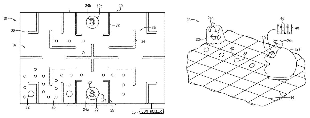
With the foregoing in mind,FIG. 1illustrates an embodiment of an interactive game floor system10in accordance with the present disclosure. The interactive game floor system10can includes one or more game vehicles12. In the illustrated embodiment, two vehicles12aand12bare positioned and configured to move on a game floor14. The system10includes a game controller16that is communicatively coupled to the vehicle/s and the game floor14and that receives vehicle position information. An operator interface20controls vehicle movement and direction on the game floor and may include, for example, a steering wheel, brake and gas pedals, a joystick, a display screen, one or more buttons, etc. The passenger seat22may accommodate one or more vehicle riders24. In certain embodiments, when multiple riders24are present in a single vehicle12, the operator interface20may provide split control to both riders. For example, one rider24may control rotation or direction of the vehicle12while the other rider24controls the speed.
The game floor14may be configured to display game images and may be a self-illuminated surface. In one embodiment, the game floor14is an LCD or LED display surface that is configured to respond to inputs from a vehicle12. The game floor14may be part of an arena or other game location. Further, the game floor14may include additional components, such as sensors, that facilitate position tracking of the vehicles12.
The depicted game floor system10includes two vehicles12aand12bwith respective riders24aand24b. Depending on the type of game configuration, the riders24aand24bmay be competing on opposing teams or may be working together to accomplish a joint goal. For team-based play, the vehicles12may be scored individually as well as cumulatively. The game floor14has a displayed game configuration28that includes interactive elements30. The interactive elements30may also include one or more bonus elements32that may or may not be displayed with a different image relative to the other interactive elements30. The interactive elements may be displayed with any size, shape, or color, depending on theme of the game. For example, for a pirate-themed game, the interactive elements30may be displayed as treasure items, such as gold or jewels. There may be any number of interactive elements30, depending on the game goals. The game floor14may also include additional displayed elements that are not interactive but that contribute to the overall theme or aesthetic effect of the game.
The depicted game configuration28also includes boundaries34, such as boundaries defining a maze with a permitted vehicle path area36. In one embodiment, the boundaries34are displayed in a different color than other game elements to permit easy identification by the riders24. As noted, the boundaries34are not physical boundaries and are displayed images on the game floor14. However, in certain embodiments, the system10may include physical components, including physical representations of items or characters that are part of particular games or physical boundaries. The vehicles12are prevented from driving on or over the boundaries34by one or more of a vehicle control or a game control system, as provided herein. The system10may also includes a game start area38, which is adjacent to a rider loading area40for each vehicle12in the illustrated embodiment.
In operation, the game system (e.g., the game system10ofFIG. 1) starts the game and the riders24drive their vehicles12onto the game floor14. WhileFIG. 1depicts a two-player game, it should be understood that the techniques disclosed herein may be applied to games with one or more vehicles12. As each rider24operates his respective vehicle12on the game floor14, their score may be determined based on the vehicle interaction with the game floor14and the path of the vehicle12with the allotted game time.
FIG. 2is a perspective view of the vehicles12aand12band their respective riders24aand24b. The riders24drive their vehicles12along the floor14to particular areas42(which, for example, may be defined by grid lines42that may or may not be displayed on the floor14) associated with interactive elements30are displayed. Once the vehicle12drives over the interactive element30, it changes (e.g., changes color) or disappears from the floor display to indicate a point collection. The operator interface20may include a display screen46for reproducing the real-time interactive floor display, and may also include displayed avatars48for each vehicle12. Based on the desired type of game, the vehicles12may be configured to resemble particular theme characters from popular games, video games, movies, or TV shows, in one example
FIG. 3is a flow diagram of a method50of assigning scores to one or more riders24based on their vehicle paths during game play. The method50may be performed entirely or in part by a game floor controller as provided herein using control logic or programming (e.g., via controller16). At block52, a controller receives one or more signals with vehicle position information. The position information may be absolute position in space, from which a position relative to the game floor14is determined or may include relative position information, e.g., a position of a vehicle12relative to the game floor14, provided by sensing components associated with the game floor14or by a camera-based detection system. After a vehicle position relative to the game floor14is determined at step52, the method50determines if the vehicle12is positioned over a scoring location on the game floor14. For example, a scoring location may be coincident with the location of any or a certain subset of displayed interactive elements30. If the vehicle12is positioned over the scoring location, a score assigned to the vehicle12is updated according to the point value of the scoring location at step58. In this manner, a vehicle12may capture an interactive element30. If the location is not positioned over a scoring location, the score is unchanged at step60. The method50tracks the progress of the game and the scores of particular vehicles12and/or riders24by returning to step52to process new position information as the vehicles12cover the game floor14during game play.
The interactive elements30may be associated with positive or negative point scores. In addition, the bonus elements32may have elevated point scores. Alternatively, a bonus element32may permit the vehicle12that captured the bonus element32(i.e., drove over it), to have special privileges in the game relative to other game players. For example, that vehicle12may be permitted to exceed certain speed thresholds relative to other vehicles in the game, change previously-defined roles within the game (e.g., change from prey to predator or vice versa), or enter previously excluded areas of the game floor14. In one embodiment, the game system10may enter a special game round upon capture of a bonus element32(or based other performance metrics, such as achieving a particular point score, remaining bump free for a period of time, or bumping a certain number of vehicles) by a vehicle12. The special game round may include additional displayed effects from the game floor14(e.g., flashing boundaries34or a change in the color scheme of all elements displayed, including the boundaries34and the interactive elements30) as well as effects on the vehicles12, such as light effects, a change in vehicle configurations or permissions (e.g., switching all prey cars to predator cars and vice versa, slowing particular game vehicles12and/or speeding up other vehicles12), and special effects or bonus information (e.g., game clues or special messages) displayed on the individual vehicle display screens46. Upon expiration of the special game round, the game floor14may return to the normal configuration.
After an interactive element30has been captured by a vehicle12(i.e., driven over for the first time in the game), the controller16provides instructions to the game floor14to change the display at that location. In an example in which the interactive elements30are displayed in a particular color, a captured interactive element may be displayed in a different color. Alternatively, a captured interactive element30may disappear from the game floor display. In addition to displayed changes, the interactive elements30may be configured to assign their associated point score only upon first capture and not to other vehicles that subsequently drive over the location of a captured interactive element30. However, in certain embodiments, an interactive element30may be configured to change into a different type of interactive element30upon capture, which may then be captured by another vehicle12.
In addition to or instead of scoring via interactive elements30, vehicles that are in a multi-vehicle game may also interact with one another to score points. While the game system10may be configured so that individual vehicles12are competing against all other vehicles12in a traditional bumper cars game, more complex game play is also contemplated. As shown inFIG. 4, a game may be configured so that vehicles of type 1 (marked as 1) are all on a first team and vehicles of type 2 (marked as 2) are all on a second team. One object of the game may be to “bump” into the opposing team's vehicles. A bump may be designated as a distance between two vehicles on opposing teams that is less than a predetermined threshold such that actual physical contact between any two vehicles12can be avoided. Vehicles12on opposing teams that are a distance d1that is greater than the threshold from one another may not be considered to be bumped and, therefore, may not experience a change in point total while vehicles that are a distance d2from one another that is less than the threshold may experience an increase in their point total. Further, the game system10may also be configured to distinguish same team bumping (i.e., vehicles from the same team that are a distance d3apart that is less than the bump threshold). Bumping may also be determined via entry into an impact zone of a vehicle12. The impact zone may be defined by an imaginary circle around the vehicle12with the radius of the bump safe distance, or may be the regions (e.g., in front of and in back of the vehicle12) on the path that are covered by such circle.
In one embodiment, the game may be configured so that certain roles are assigned to certain vehicles12. For example, in one embodiment, only one team is the bumping team (i.e., the predator team) whose object is to bump the other team (i.e., the prey team), who in turn have a different game goal involving the interactive elements30.FIG. 5is a flow diagram of a method80of scoring such a game configuration. At step82, a controller, i.e., a game controller16, receives position information for a first subset of vehicles corresponding to the prey team and a second subset of vehicles corresponding to the predator team. To score the first subset, the method80determines the position of each vehicle in that subset relative to the game floor14at step84and assigns the score accordingly at step86. For example, the score for an individual vehicle12may be assigned based on whether the position corresponds to an interactive element30available for capture. The more interactive elements30a particular vehicle12passes over (captures), the more points assigned to that vehicle12and/or the associated team. The method80may determine scores for individual vehicles12as well as a team score for the prey team. Scores are updated as the vehicle paths progress over the game floor14and the method80returns to step82.
For the predator team, after determining position information at step90for each vehicle in the second subset relative to each vehicle in the first subset, the scores are assigned at step92based on whether any of the vehicles in the second subset are within the bumping distance threshold. In addition to or instead of being determined by position information, bumping may also be determined by other sensors, such as impact sensors associated with each vehicle12. Again, the scores update throughout the game as the method returns to step82to assess bumping as the vehicles12move on the game floor14.
In one embodiment, the prey team does not receive points or instead receives a penalty for initiating or receiving a bump from any vehicle, including their own teammates. That is, the prey team may only score via the interactive elements30. Similarly, the predator team may receive a score for bumping only an opposite team member and not a teammate. It is also envisioned that bumps may be unscored, but that the predator team may win by preventing the prey team from achieving a particular score goal. Further, the bumped prey vehicle may have a penalty assessed, such as a point deduction or other penalty (e.g., a frozen vehicle for a certain amount of time, a system override to return the vehicle to the game start or game loading site before the rider can control the vehicle again). By configuring a game for prey and predator teams, the game goals are more complex relative to a simple bumper cars game where any other vehicle is a potential target for bumping. That is, the prey vehicles have the incentive to avoid the predator team to avoid being bumped to in turn achieve higher point totals.
Further, the game system10may also mediate vehicle speed on the game floor14to allow cars to increase their speed to relatively high levels so long as no other vehicle is within a threshold distance. In this manner, the vehicle speed variability may be greater relative to traditional bumper cars games. The system10may also control vehicle speed when vehicles12are close to one another, regardless of any team designation.FIG. 6is flow diagram of a method100of controlling vehicle speed in the game. Using the vehicle position information received at step102, the controller determines if any two vehicles12are within a predetermined distance of one another at step104and provides override instructions to slow the vehicle speed for any two vehicles12too close to one another at step106. While the vehicles12may bump into one another, the bump is controlled. Alternatively, the controller may provide instruction to control the speed and position of two vehicles12involved in a potential bump so that the actual vehicles12are prevented from impact. However, both vehicles may simulate the feel of an impact with additional vehicle features (e.g., vibration, impact sounds, jerking motion, etc.) that are controlled via the game controller or the vehicle controller. Such an embodiment may prevent impact wear to the vehicles12.
By providing certain features of the game via the game floor14, the system10may be reconfigured by changing the displayed images.FIG. 7is an example of a single vehicle12configuration110on a game floor14that transitions to a multi-vehicle12configuration112, with different boundaries34and interactive elements30. In some embodiments, additional vehicles12or participants may be virtually presented on the floor14or physical vehicles12may be activated and controlled by the controller16and/or by player-controlled remote controllers. As shown in the flow diagram ofFIG. 8, the method120of configuring and reconfiguring the game floor14may include a step122of accessing a first game display having a first configuration from a set of stored game configurations and displaying the first game display on a game floor surface at step124. After the first game configuration is played and the game information is received at step126, the first game display is cleared at step128upon operator instructions to change the game display or based on the game information. For example, if the players achieve a certain score, the system accesses a second game display having a second game configuration at step130and displays the second game display at step132.
In another embodiment, the game display may be selected based on the number of riders24and corresponding vehicles12and/or the skill of the game players. For example, an amusement park may track player progress over the course of park visits in various games, e.g., via a card or mobile device. When a player or group of players returns to a game, the game controller16may select a game display based on previously played games. In this manner, a single game location is capable of providing challenges for more experienced players as well as novice players. Further, for games played with a mix of player skill levels, the game controller16may introduce additional challenges for more advanced players.
As shown inFIG. 9, which is a block diagram of the system10, the techniques disclosed herein may be used in conjunction with one or more components of the system10, including the vehicle12, the game floor14, and the game controller16. To provide movements of the vehicle12, the vehicle12includes a motor138and a brake140. The movements of the vehicle12may include running (e.g., acceleration, deceleration), turning, and stopping of the vehicle12. The motor138may be powered by any suitable power source142, including, but not limited to, a battery, a solar panel, an electrical generator, a gas engine, or any combination thereof. The operations of the motor138and the brake140may be controlled by the vehicle controller150. For example, the vehicle controller150may control the motor138to adjust its output power to accelerate or decelerate the vehicle12. The vehicle controller150may also control the brake140to decelerate or stop the vehicle12. Further, the vehicle controller150may operate under instructions from the rider via the operator interface20(e.g., to steer the vehicle based on operator control of a steering wheel or joystick) or from the game controller16, which may override rider instructions.
The vehicle12may include a position tracking system154for monitoring its position on the game floor14. In one embodiment, the position tracking system154interacts with sensors155in the game floor14. Each sensor155represents a unique location (e.g., coordinates relative to one or more reference points) on the floor14. In such an embodiment, the vehicle position tracking system154includes a reader that may sense the sensor155to provide the position information of the vehicle12. The reader then supplies the position information to the vehicle controller154, which in turn provides the information to the game controller16. The vehicle12may include a communication module156to facilitate communication with the game controller16. Based on feedback from the game controller16, the vehicle12may also display game information via a display module160coupled to a display screen (e.g., display screen46inFIG. 2). Game information may include a vehicle score as well as a team score, a representation of the game floor14(e.g., a 2D dynamic graphical display including the current game configuration and vehicle positions on the game floor14as well as any available interactive elements30).
The game controller16and the vehicle controller150may include various components that may allow for interaction with the vehicle12and the display circuitry170of the game floor14. While these elements are discussed in the context of the game controller16, it should be understood that the vehicle controller150and the game floor14may include similar components. The vehicle controller16may include a distributed control system (DCS) or any computer-based workstation including an input/output interface174and a display176and that is fully or partially automated. For example, the vehicle controller16may be any device employing a general purpose or an application-specific processor180. The vehicle controller16may also include a memory device182for storing instructions executable by the processor38to perform the methods and control actions described herein for the vehicle12. The processor180may include one or more processing devices, and the memory182may include one or more tangible, non-transitory, machine-readable media. By way of example, such machine-readable media can include RAM, ROM, EPROM, EEPROM, CD-ROM, or other optical disk storage, magnetic disk storage or other magnetic storage devices, or any other medium which can be used to carry or store desired program code in the form of machine-executable instructions or data structures and which can be accessed by the processor180or by any general purpose or special purpose computer or other machine with a processor. In addition, the game controller16may be configured to communicate over wired or wireless communication paths with the game floor14and the vehicle12.
In one embodiment, data is transferred between the game controller16, the game floor14, and the vehicle controller150at least in part via a wireless network. The vehicle controller150may transfer data indicative of the status of the vehicle to the game controller16. Such data may include a vehicle identifier for an individual vehicle12and associated position, velocity, impact zone, traveling direction, motor output power, loading condition, or the like. Based on the received data from the vehicle controller150, the game controller16may send instructions to the vehicle controller150to control the movement of the vehicle12. For example, the game controller16may compare the impact zones of all ride vehicles in the course to determine if any of the two ride vehicles have collided based on their traveling velocities, current positions on the game floor14, and traveling directions. If so, the game controller16may, for example, update a game score and control vehicle speed. In accordance with the present disclosure, the game controller16may control each of a plurality of ride vehicles independently.
The system10may determine vehicle position via the position tracking system154that interacts with sensors155on or in the game floor14or other suitable techniques for determining vehicle position. For example, the system10may include an external sensor190, such as a camera, that tracks the positions of the vehicles12and provides data to the game controller16. In addition, the vehicle12may include transmitters, such as RFID transmitters, that provide signals to the game controller16and that may be used to determine position information. Further, while the disclosed embodiments have been described in the context of vehicles12, in other embodiments, the game players may interact directly with the game floor14. In such an embodiment, game players may wear watches or other objects that can incorporate position indicating devices. Alternatively, player location may be determined via the external sensor190.
While only certain features of the present embodiments have been illustrated and described herein, many modifications and changes will occur to those skilled in the art. It is, therefore, to be understood that the appended claims are intended to cover all such modifications and changes as fall within the true spirit of the present disclosure. Further, it should be understood that certain elements of the disclosed embodiments may be combined or exchanged with one another.
Claims
- A system comprising: a surface configured to display a plurality of images related to a game;a vehicle configured to accommodate a rider and comprising interface circuitry configured to receive an input from the rider related to a vehicle path on the surface, wherein the vehicle operates according to the input to move on the vehicle path on the surface;and a controller configured to: determine that the vehicle has moved over a first image of the plurality of images while on the vehicle path based on a signal from the vehicle, the surface, an external sensor, or a combination thereof;provide instructions to display circuitry associated with the surface to change the first image when the vehicle has moved over the first image while on the vehicle path;and update a score associated with the vehicle when the vehicle has moved over the first image while on the vehicle path.
- The system of claim 1 , wherein the surface is self-illuminated.
- The system of claim 1 , wherein the surface comprises one or more sensors configured to detect a position of the vehicle on the surface and provide the signal.
- The system of claim 1 , wherein the vehicle comprises one or more transmitters configured to provide the signal.
- The system of claim 1 , wherein the controller is configured to determine that the vehicle has moved over the first image of the plurality of images based on the signal from the external sensor, wherein the external sensor comprises a camera.
- The system of claim 1 , wherein the vehicle comprises a display module configured to receive and display the score from the controller.
- The system of claim 1 , wherein the instructions to change the first image comprise instructions to change a color of the first image.
- The system of claim 1 , wherein the instructions to change the first image comprise instructions to stop displaying the first image.
- The system of claim 1 , wherein the surface comprises one or more regions that are excluded from the vehicle path by the controller.
- The system of claim 9 , wherein the one or more regions are displayed on the surface as path boundaries.
- The system of claim 9 , wherein the controller is configured to provide a control input to the vehicle to override the input from the rider and prevent the vehicle from moving over the one or more regions.
- The system of claim 1 , wherein the controller is configured to provide a speed input to the vehicle to control a vehicle speed on the vehicle path when a second signal from a second vehicle is received that indicates that the second vehicle is a distance from the vehicle that is less than a threshold.
- The system of claim 1 , wherein the controller is configured to provide an input to the vehicle to override a second input from the rider that would result in a vehicle speed over a threshold.
- The system of claim 1 , wherein the controller is configured to: determine that the vehicle has moved over a second image of the plurality of images while on the vehicle path based on a second signal from the vehicle, the surface, the external sensor, or a combination thereof;provide instructions to the display circuitry associated with the surface to change the second image when the vehicle has moved over the second image while on the vehicle path;and update the score associated with the vehicle when the vehicle has moved over the second image while on the vehicle path.
- A method comprising: receiving one or more signals related to a plurality of vehicle positions for a plurality of vehicles;assigning a first group of scores to a first subset of the plurality of vehicles based on vehicle positions of the first subset relative to a floor surface;and assigning a second group of scores to a second subset of the plurality of vehicles based on a location of respective vehicles of the second subset relative to respective vehicles of the first subset, wherein assigning the second group of scores comprises increasing a score of an individual vehicle in the second subset upon the individual vehicle entering within a predetermined distance of any vehicle in the first subset.
- The method of claim 15 , comprising updating the first group of scores and the second group of scores based on vehicle paths of the first and second subsets over time.
- The method of claim 15 , wherein the first subset and the second subset are nonoverlapping.
- The method of claim 15 , wherein each vehicle of the plurality of vehicles is under control of a respective rider positioned therein.
- The method of claim 15 , wherein assigning the first group of scores comprises increasing a score of any vehicle in the first subset that is positioned on one of a plurality of predetermined locations on the floor surface.
- The method of claim 15 , wherein assigning the first group of scores comprises decreasing a score of any vehicle in the first subset that is within a second predetermined distance of any second vehicle in the second subset.
- The method of claim 15 , comprising applying a motion penalty to any vehicle in the first subset that is within a second predetermined distance of any second vehicle in the second subset.
- The method of claim 21 , wherein the motion penalty comprises a period that the vehicle in the first subset cannot move or a rider override.
- The method of claim 21 , wherein the motion penalty comprises a return of the vehicle in the first subset to a game start position.
- A controller for a game system comprising: a memory storing instructions that, when executed, are configured to: access a first game display;provide instructions to display circuitry of a game floor surface to display the first game display, wherein the first game display comprises a first game configuration and a first set of displayed images;receive one or more signals indicative of movement of individual vehicles on the game floor surface;assign scores to the individual vehicles based on the movement and the first game configuration;access a second game display;and provide instructions to the display circuitry of the game floor surface to display the second game display, wherein the second game display comprises a second game configuration comprising different vehicle paths for the individual vehicles relative to the first game display and a second set of displayed images;and a processor configured to execute the instructions.
- The controller of claim 24 , wherein the second game display is selected from a plurality of game displays based on the scores.
Disclaimer: Data collected from the USPTO and may be malformed, incomplete, and/or otherwise inaccurate.