U.S. Pat. No. 9,908,043
GUITAR SHAPED VIDEO GAME CONTROLLER
AssigneePerformance Designed Products LLC
Issue DateApril 25, 2016
Illustrative Figure
Abstract
A guitar-shaped video game controller includes a body having a shape that resembles a guitar body, and a neck that is pivotally coupled to the guitar body via a hinge so that the neck can pivot between an extended position and a folded position relative to the guitar body. A latch assembly is actuatable to selectively lock the neck in the extended position to the body. A cable extends between and electrically connects the neck and the body to maintain an electrical connection between the neck and the body when the neck is in the extended and the folded positions.
Description
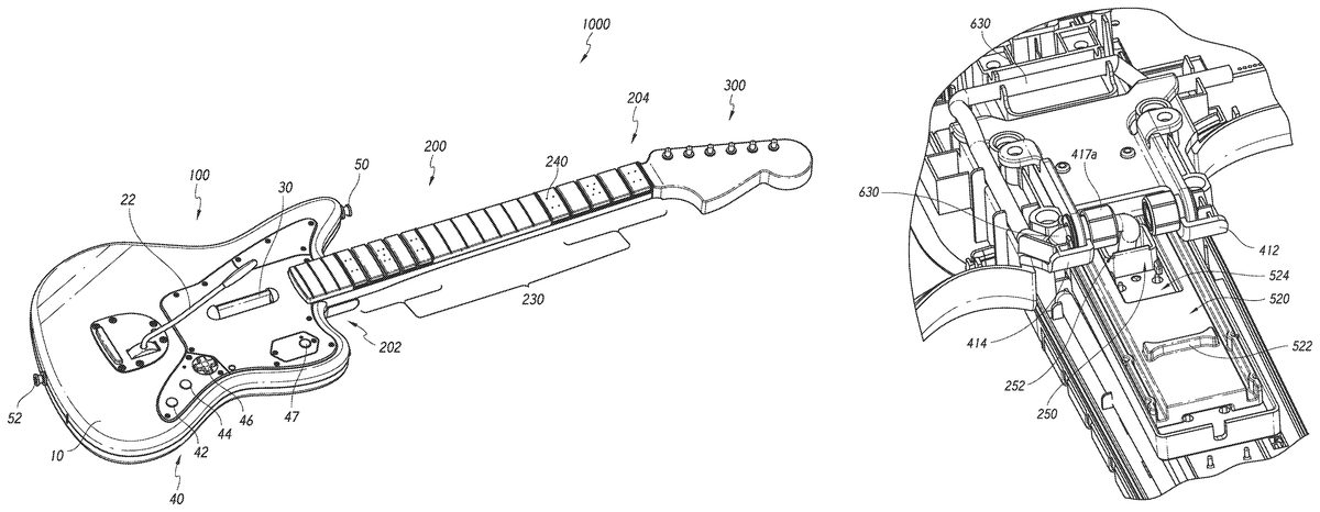
DETAILED DESCRIPTION FIGS. 1-2show one embodiment of a video game controller. In the illustrated embodiment, the video game controller is a guitar-shaped video game controller1000(“controller”). The controller1000has a body100, a neck200and a headstock300. The body100has a shape resembling a body of the guitar, and includes a front surface or cabinet10and a rear surface or cabinet20. The body100also optionally includes a whammy bar22, a strum bar30, strap pegs50,52, and input buttons40. In the illustrated embodiment, the input buttons40include an options button42, a share button44, a D-pad46and a guide button47. In other embodiments, the input buttons100can be more or fewer than those shown inFIG. 1. The neck200has a shape that resembles a neck of a guitar, and extends from a proximal portion202to a distal portion204. The neck200includes a fret board205with fretboard dots240and a plurality of fret buttons230. The headstock300has a shape that resembles a headstock of a guitar. Therefore, a user playing a video game with the controller1000can pretend they are playing an actual guitar while playing the video game. With reference toFIG. 2, the controller1000includes a hinge assembly400that advantageously allows the neck200to pivot between an extended position (shown inFIGS. 1-2) and a folded position (shown, for example, inFIGS. 8, 10-13) relative to the body100. For example, the neck200can be in the folded position when packaged or for storage, allowing for a smaller package or storage space to be used, and can readily be moved to the extended position by the user when the user wants to use the controller1000to play a video game. The hinge assembly400includes a yoke410that has a pair of arms412,414and a knuckle416that extends between and is pivotally coupled to the arms412,414by a pin (417inFIG. 7A-7B) or pair of bosses (417ainFIG. 17) that extend between one or both of the arms412,414and the knuckle416, as discussed further below. In the ...
DETAILED DESCRIPTION
FIGS. 1-2show one embodiment of a video game controller. In the illustrated embodiment, the video game controller is a guitar-shaped video game controller1000(“controller”). The controller1000has a body100, a neck200and a headstock300.
The body100has a shape resembling a body of the guitar, and includes a front surface or cabinet10and a rear surface or cabinet20. The body100also optionally includes a whammy bar22, a strum bar30, strap pegs50,52, and input buttons40. In the illustrated embodiment, the input buttons40include an options button42, a share button44, a D-pad46and a guide button47. In other embodiments, the input buttons100can be more or fewer than those shown inFIG. 1.
The neck200has a shape that resembles a neck of a guitar, and extends from a proximal portion202to a distal portion204. The neck200includes a fret board205with fretboard dots240and a plurality of fret buttons230. The headstock300has a shape that resembles a headstock of a guitar. Therefore, a user playing a video game with the controller1000can pretend they are playing an actual guitar while playing the video game.
With reference toFIG. 2, the controller1000includes a hinge assembly400that advantageously allows the neck200to pivot between an extended position (shown inFIGS. 1-2) and a folded position (shown, for example, inFIGS. 8, 10-13) relative to the body100. For example, the neck200can be in the folded position when packaged or for storage, allowing for a smaller package or storage space to be used, and can readily be moved to the extended position by the user when the user wants to use the controller1000to play a video game.
The hinge assembly400includes a yoke410that has a pair of arms412,414and a knuckle416that extends between and is pivotally coupled to the arms412,414by a pin (417inFIG. 7A-7B) or pair of bosses (417ainFIG. 17) that extend between one or both of the arms412,414and the knuckle416, as discussed further below. In the illustrated embodiment, the yoke410is defined by the body100and the knuckle416is defined by the neck200. In another embodiment, the yoke410is defined by the neck200and the knuckle416is defined by the body100.
With reference toFIG. 2, the neck200has an opening208defined on a rear surface206of the neck200. Advantageously, a user can access a latch connector520of a latch assembly500(described further below) through the opening208to actuate (e.g., slide) the latch connector520between a first position, such as a retracted position, and a second position, such as a deployed position, as discussed further below. For example, the user can contact a ridge522of the latch connector520(e.g., with the user's finger(s)) to move the latch connector520relative to the neck200.
FIGS. 3-13show one embodiment of the controller1000.FIG. 4shows the body100with the front surface or cabinet10removed to illustrate components housed in the body100, including one or more printed circuit boards (PCBs)150and a battery compartment160that is accessed via a cover170(seeFIG. 6).
In the illustrated embodiment, a ribbon cable610extends between the body100and the neck200. Advantageously, the ribbon cable610provides an electrical connection between the neck200and body100irrespective of the position of the neck200relative to the body100(e.g., irrespective of whether the neck200is in the extended or folded positions), and therefore the ribbon cable610maintains an electrical connection between the neck200and the body100. The ribbon cable610can provide an electrical connection between the fret buttons230and the body100(e.g., between the fret buttons230and the PCBs150). As shown inFIG. 5, the neck200can have one or more fret button pads235that underlie the fret buttons230. The fret button pads235can be disposed on one or more circuit boards250, and the circuit board250can be electrically connected with an end of the ribbon cable610via a PCB connector215. Accordingly, the signal provided by the user when pressing the fret buttons230can be communicated via the circuit board250and ribbon cable610to the body100(e.g., to the PCBs150in the body100, which can then communicate the signals to the video game (e.g., via a wired or wireless connection).
As shown inFIGS. 7A-7B, the ribbon cable610extends into the neck200through an opening416ain the knuckle416and extends into the body100via an opening140. An end612of the ribbon cable610connects to a PCB connector614in the body100(e.g., where the PCB connector614is connected to the one or more PCBs150).
A tension assembly170is disposed in the body100and advantageously applies a tension force on the ribbon cable610to inhibit slack in the ribbon cable610as the neck200is pivoted between the extended and the folded positions, which advantageously inhibits (e.g., prevents) damage to the ribbon cable610during operation of the controller1000. The tension assembly170includes a first pin or roller172(e.g., distal pin) and a second pin or roller174(e.g., proximal pin), where the ribbon cable610wraps around at least a portion of the first and second pins172,174(e.g., in a zig zag manner) between the opening140and the connector614. In the illustrated embodiment, the first pin172is fixed and the second pin174is part of a hook structure176that is attached by a spring178to a support member179to thereby spring load the second pin174and allow the second pin174to move axially along a longitudinal direction of the controller1000. The spring178applies a force on the second pin174that biases the second pin174toward the support179, and thereby applies a tension force on the ribbon cable610that wraps about the second pin174, so that there is substantially no slack in the portion of the ribbon cable610that extends between the opening140in the body100and the opening416ain the knuckle.
As the neck200is moved to the folded position, the ribbon cable610is pulled out of the opening140by the rotation of the knuckle416, but the second pin174applies a tension force on the ribbon cable610(via the tension force applied by the spring178) to maintain the ribbon cable610substantially taut between the second pin174and the PCB connector215. As shown inFIGS. 7A-8, the spring178is in an extended position when the neck200is in the folded position due to a larger length of the ribbon cable610extending out of the body100through the opening140. The farther the neck200is rotated toward the folded position, the greater the length of the ribbon cable610that extends out of the body100and the greater the tension force applied on the ribbon cable610by the spring178(via the second pin174). In one embodiment, the second pin174and hook structure176can be disposed in a channel so that they are substantially limited to move in only the fore-aft direction (e.g., to substantially inhibit movement of the second pin174and hook structure176in a lateral direction). In another embodiment, the tension assembly170can have only one pin about which the ribbon cable610is wrapped, where said pin is spring loaded and biased away from the opening140in the body100.
With continued reference toFIGS. 7A-7B, a latch assembly500includes the latch connector520and a connector540in the body100. In the illustrated embodiment, the connector540is a slot540in the body100. The slot540receives a distal portion526of the latch connector520when it is slid in a direction X toward the body100such that it extends past a proximal end202aof the neck200to thereby lock the neck200in the extended position to the body100. In one embodiment, the distal portion526of the latch connector520can engage a ridge or protrusion in the slot540to lock the position of the latch connector520in the slot540and inhibit inadvertent disengagement between the latch connector520and the slot540.
In the extended position, the proximal portion202of the neck200extends into a recess110of the body100and a proximal surface203(see e.g.,FIG. 8) of the neck200is disposed adjacent a surface112of the recess110. Additionally, a ridge203aof the proximal portion202of the neck200extends into a groove112ain the surface112to facilitate the coupling of the neck200to the body100. In one embodiment, the ridge203aand groove112aare press-fit when coupled together to inhibit movement of the neck200relative to the body100prior to sliding the latch connector520to the deployed position. In one embodiment, in the first or retracted position the distal portion526of the latch connector520can be flush with the proximal end202aof the neck200. In another embodiment, in the first or retracted position the distal portion526of the latch connector520can be disposed distal of the proximal end202aof the neck200. As shown inFIG. 8, in one embodiment where the neck200is in the folded position relative to the body100, the neck200can be adjacent (e.g., in contact with) the bottom surface or cabinet20of the body100. In another embodiment, the latch connector520can be disposed in the body100and slide out of the body100to engage a connector (e.g., slot) in a proximal end202aof the neck200. In such an embodiment, the window208can instead be defined in the body100to allow the user to access the latch connector to move the connector between the retracted and deployed positions to lock the neck200to the body100or allow the neck200to pivot relative to the body100.
FIGS. 10-13show the controller1000with the neck200in the folded position relative to the body100. In the folded position, the controller1000can have a width W of between about 200 mm and about 300 mm, in some embodiments about 275 mm. In the folded position, the controller1000can have a length L of between about 400 mm and about 500 mm, in some embodiments about 430 mm. In the folded position, the controller1000can have a thickness T of between about 50 mm and about 100 mm, in some embodiments about 75 mm. The controller1000in the folded position can be packaged or stored in a box or space having a length of between about 400-500 mm, in some embodiments about 450 mm, a width of between about 200-300 mm, in some embodiments about 280 mm, and a thickness of between about 75 mm-150 mm, in some embodiments about 100 mm.
As shown inFIGS. 10-13, in the folded position, the headstock300can be removed from the distal end204of the neck200so that the distal connector204a(e.g., one or more prongs) of the neck200is decoupled from the connector302(e.g., one or more slots) of the headstock300. The neck200can be folded relative to the body100so that it is disposed adjacent the bottom surface of cabinet20of the body100.
FIGS. 14-19show another embodiment of the controller1000. The controller1000illustrated inFIGS. 14-19is similar to the controller100shown inFIGS. 3-13, except as noted below. Thus, the reference numerals used to designate the various components of the controller1000inFIGS. 14-19are identical to those used for identifying the corresponding components of the controller1000inFIGS. 3-13.
In the illustrated embodiment, a cable630(e.g., electrical cable) extends between the neck200and the body100. As shown inFIG. 15, the cable630can connect with the one or more circuit boards250on which the fret button pads235are disposed. In the illustrated embodiment, two circuit boards250for the fret button pads235are disposed in the neck200, and electrically connected by the cable630. The cable630extends through the hinge assembly400and into the body100(e.g., so that no portion of the cable630is exposed outside of the controller1000). The cable630extends from the proximal portion202of the neck200into the knuckle416, and passes through a channel416ain the knuckle416into one of the arms414of the yoke410through an opening in the arm414a, to thereby pass into the body100where the cable630connects with one or more PCBs150in the body. Accordingly, the signal provided by the user when pressing the fret buttons230that overlie the fret button pas235can be communicated via the circuit board(s)250and cable630to the body100(e.g., to the PCBs150in the body100, which can then communicate the signals to the video game (e.g., via a wired or wireless connection).
With reference toFIGS. 17-19, the cable630passes from the proximal portion202of the neck200into the knuckle416via an opening252in a conduit250, defined by walls250a,250b, that extends through an opening524in the latch connector520. The conduit250advantageously protects the cable630from damage by the latch connector520while the latch connector520is moved between the retracted position (shown inFIG. 18B), where the neck200is unlatched from the body100so that the neck200is able to pivot relative to the body100, and the deployed position (shown inFIG. 18A) along direction X, where the neck200is latched to (or locked to) the body100with the neck200in the extended position. As the latch connector520is slid between the retracted and deployed positions, the latch connector520can slide until a portion of the latch connector520contacts one of the walls250a,250b, which prevents the latch connector520from contacting (and possibly damaging) the cable630that extends through the conduit250. As discussed above, in one embodiment, the distal portion526of the latch connector520can engage a ridge or protrusion in the slot540to lock the position of the latch connector520in the slot540and inhibit inadvertent disengagement between the latch connector520and the slot540. Advantageously, the cable630provides an electrical connection between the neck200and body100irrespective of the position of the neck200relative to the body100(e.g., irrespective of whether the neck200is in the extended position, as shown in FIGS.18A18B, or in the folded position, as shown inFIG. 19), and therefore the cable630maintains an electrical connection between the neck200and the body100. Additionally, the cable630passes through the hinge assembly400such that the cable630is not twisted while the neck200is pivoted relative to the body100. Optionally, one or both of the knuckle416and arms412,414of the yoke410can have bearings through which the cable630passes from the knuckle416into one of the arms414and into the body100.
FIG. 20shows a block diagram of a video game system2000utilizing the video game controller1000. The system2000includes a console1800that communicates with the controller1000via a wired or wireless connection. The console1800can include a bus1802, one or more processors1804, a main memory1806, a read-only memory (ROM)1808, a storage device1810and a communication interface1818. The one or more processors1804can execute video game instructions, for example in a memory1806or ROM1808that communicates with the one or more processors1804. The instructions can be stored in the storage device1810, and transferred to the memory1806and/or ROM1808as commanded by the processor(s)1804. The console1800can receive inputs from the controller1000(i.e., from the user pressing on the fret buttons230or operating the whammy bar22or strum bar30), and can communicate with a display1830via the communication interface1818to provide display data (e.g., images) to the display (e.g., computer monitor, television, etc.).
Although this disclosure describes certain embodiments and examples of video game controllers, it will be understood by those skilled in the art that many aspects of the methods and devices shown and described in the present disclosure may be differently combined and/or modified to form still further embodiments or acceptable examples. All such modifications and variations are intended to be included herein within the scope of this disclosure. Indeed, a wide variety of designs and approaches are possible and are within the scope of this disclosure. No feature, structure, or step disclosed herein is essential or indispensable. Moreover, while illustrative embodiments have been described herein, the scope of any and all embodiments having equivalent elements, modifications, omissions, combinations (e.g., of aspects across various embodiments), adaptations and/or alterations as would be appreciated by those in the art based on the present disclosure.
Furthermore, certain features that are described in this disclosure in the context of separate implementations can also be implemented in combination in a single implementation. Conversely, various features that are described in the context of a single implementation can also be implemented in multiple implementations separately or in any suitable subcombination. Moreover, although features may be described above as acting in certain combinations, one or more features from a claimed combination can, in some cases, be excised from the combination, and the combination may be claimed as a subcombination or variation of a sub combination.
Moreover, while operations may be depicted in the drawings or described in the specification in a particular order, such operations need not be performed in the particular order shown or in sequential order, or that all operations be performed, to achieve desirable results. Other operations that are not depicted or described can be incorporated in the example methods and processes. For example, one or more additional operations can be performed before, after, simultaneously, or between any of the described operations. Further, the operations may be rearranged or reordered in other implementations. Also, the separation of various system components in the implementations described above should not be understood as requiring such separation in all implementations, and it should be understood that the described components and systems can generally be integrated together in a single product or packaged into multiple products.
For purposes of this disclosure, certain aspects, advantages, and novel features are described herein. Not necessarily all such advantages may be achieved in accordance with any particular embodiment. Thus, for example, those skilled in the art will recognize that the disclosure may be embodied or carried out in a manner that achieves one advantage or a group of advantages as taught herein without necessarily achieving other advantages as may be taught or suggested herein.
Conditional language, such as “can,” “could,” “might,” or “may,” unless specifically stated otherwise, or otherwise understood within the context as used, is generally intended to convey that certain embodiments include, while other embodiments do not include, certain features, elements, and/or steps. Thus, such conditional language is not generally intended to imply that features, elements, and/or steps are in any way required for one or more embodiments.
Conjunctive language such as the phrase “at least one of X, Y, and Z,” unless specifically stated otherwise, is otherwise understood with the context as used in general to convey that an item, term, etc. may be either X, Y, or Z. Thus, such conjunctive language is not generally intended to imply that certain embodiments require the presence of at least one of X, at least one of Y, and at least one of Z.
Language of degree used herein, such as the terms “approximately,” “about,” “generally,” and “substantially” as used herein represent a value, amount, or characteristic close to the stated value, amount, or characteristic that still performs a desired function or achieves a desired result. For example, the terms “approximately”, “about”, “generally,” and “substantially” may refer to an amount that is within less than 10% of, within less than 5% of, within less than 1% of, within less than 0.1% of, and within less than 0.01% of the stated amount. As another example, in certain embodiments, the terms “generally parallel” and “substantially parallel” refer to a value, amount, or characteristic that departs from exactly parallel by less than or equal to 15 degrees, 10 degrees, 5 degrees, 3 degrees, 1 degree, 0.1 degree, or otherwise.
The language of the claims is to be interpreted broadly based on the language employed in the claims and not limited to the examples described in the present specification or during the prosecution of the application, which examples are to be construed as non-exclusive.
Some embodiments have been described in connection with the accompanying drawings. However, the figures are not drawn to scale, unless indicated otherwise. Distances, angles, etc. are merely illustrative and do not necessarily bear an exact relationship to actual dimensions and layout of the devices illustrated. Components can be added, removed, and/or rearranged. Further, the disclosure herein of any particular feature, aspect, method, property, characteristic, quality, attribute, element, or the like in connection with various embodiments can be used in all other embodiments set forth herein. Additionally, it will be recognized that any methods described herein may be practiced using any device suitable for performing the recited steps.
In summary, various illustrative embodiments and examples of video game controllers have been disclosed. Although the video game controllers have been disclosed in the context of those embodiments and examples, it will be understood by those skilled in the art that this disclosure extends beyond the specifically disclosed embodiments to other alternative embodiments and/or other uses of the embodiments, as well as to certain modifications and equivalents thereof. This disclosure expressly contemplates that various features and aspects of the disclosed embodiments can be combined with, or substituted for, one another. Accordingly, the scope of this disclosure should not be limited by the particular disclosed embodiments described above, but should be determined only by a fair reading of the claims that follow as well as their full scope of equivalents.
Claims
- A guitar-shaped video game controller, comprising: a body having a shape that resembles a guitar body and one or more control inputs;a neck pivotally attached to the body via a hinge, the neck configured to pivot between an extended position and a folded position relative to the body;a latch assembly actuatable by a user to lock the neck in the extended position to the body, the latch assembly comprising a latch connector configured to slide between a first position that allows the neck to pivot relative to the body and a second position in which the neck is locked in the extended position to the body;and an electrical cable that extends between and electrically connects the neck and the body, the electrical cable configured to extend through at least a portion of the hinge along a pivot axis of the hinge and to maintain an electrical connection between the neck and the body when the neck is in the extended and the folded positions.
- The controller of claim 1 , wherein the latch connector is disposed in a proximal portion of the neck.
- The controller of claim 1 , wherein in the first position the latch connector is retracted and in the second position the latch connector extends past a proximal end of the neck.
- The controller of claim 2 , wherein the proximal portion of the neck includes an opening through which at least a portion of the latch connector is accessible, the latch connector being actuatable by the user through the opening to slide the latch connector between the first and second positions.
- The controller of claim 2 , wherein the latch connector is a male connector that engages a female connector in the body.
- The controller of claim 5 , wherein the female connector is a slot in the body.
- The controller of claim 1 , further comprising a headstock detachable from a distal end of the neck.
- The controller of claim 1 , wherein the hinge comprises a yoke with a pair of arms and a knuckle that extends between the arms of the yoke, the knuckle configured to rotate relative to the arms when the neck is pivoted between the extended and the folded positions.
- The controller of claim 8 , wherein at least a portion of the cable passes through a channel in the knuckle and an opening in one of the arms of the yoke.
- The controller of claim 8 , wherein the knuckle is defined by the neck and the yoke is defined by the body.
- The controller of claim 1 , wherein at least a portion of the cable passes through an opening in the latch connector, such that sliding of the latch connector between the retracted and deployed positions does not contact said at least a portion of the cable that passes through the opening in the latch connector.
- The controller of claim 11 , wherein the neck defines a conduit that extends through the opening in the latch connector, the conduit having a passage through which the cable passes, the conduit inhibiting contact between the latch connector and the cable when sliding the latch connector between the retracted and deployed positions.
- The controller of claim 1 , wherein in the folded position at least a portion of the neck is disposed adjacent a rear surface of the body.
- A guitar-shaped video game controller, comprising: a body having a shape that resembles a guitar body and one or more control inputs;a neck pivotally attached to the body via a hinge, the neck configured to pivot between an extended position and a folded position relative to the body;a latch assembly actuatable by a user to lock the neck in the extended position to the body, the latch assembly comprising a latch connector in the neck that is configured to slide between a retracted position that allows the neck to pivot relative to the body and a deployed position in which the latch connector extends past a proximal end of the neck and engages a slot in the body to thereby lock the neck to the body;and an electrical cable that extends between and electrically connects the neck and the body, the electrical cable extending through at least a portion of the hinge along a pivot axis of the hinge and configured to maintain an electrical connection between the neck and the body when the neck is in the extended and the folded positions.
- The controller of claim 14 , wherein a proximal portion of the neck includes an opening through which at least a portion of the latch connector is accessible, the latch connector being actuatable by the user through the opening to slide the latch connector between the retracted and deployed positions.
- The controller of claim 14 , further comprising a headstock detachable from a distal end of the neck.
- The controller of claim 14 , wherein the hinge comprises a yoke with a pair of arms and a knuckle that extends between the arms of the yoke, the knuckle configured to rotate relative to the arms when the neck is pivoted between the extended and the folded positions.
- The controller of claim 17 , wherein at least a portion of the cable passes through a channel in the knuckle and an opening in one of the arms of the yoke.
- The controller of claim 17 , wherein the knuckle is defined by the neck and the yoke is defined by the body.
- The controller of claim 14 , wherein at least a portion of the cable passes through an opening in the latch connector, such that sliding of the latch connector between the retracted and deployed positions does not contact said at least a portion of the cable that passes through the opening in the latch connector.
- The controller of claim 20 , wherein the neck defines a conduit that extends through the opening in the latch connector, the conduit having a passage through which the cable passes, the conduit inhibiting contact between the latch connector and the cable when sliding the latch connector between the retracted and deployed positions.
- The controller of claim 14 , wherein in the folded position at least a portion of the neck is disposed adjacent a rear surface of the body.
Disclaimer: Data collected from the USPTO and may be malformed, incomplete, and/or otherwise inaccurate.