U.S. Pat. No. 9,908,040
GAME CONTROLLER
AssigneeCINCH GAMING EQUIPMENT LLC
Issue DateNovember 25, 2014
Illustrative Figure
Abstract
A game controller is provided. In one embodiment, the game controller includes a main body, a trigger device, and a first adjustment mechanism. The trigger device has a trigger body coupled to the main body and that pivots along a pivotal axis relative to the main body. The first adjustment device has a first surface that contacts a second surface of the main body at a first point of contact when the trigger body is moved. The first adjustment device is movable along a first axis such that the first point of contact is adjusted along the first axis.
Description
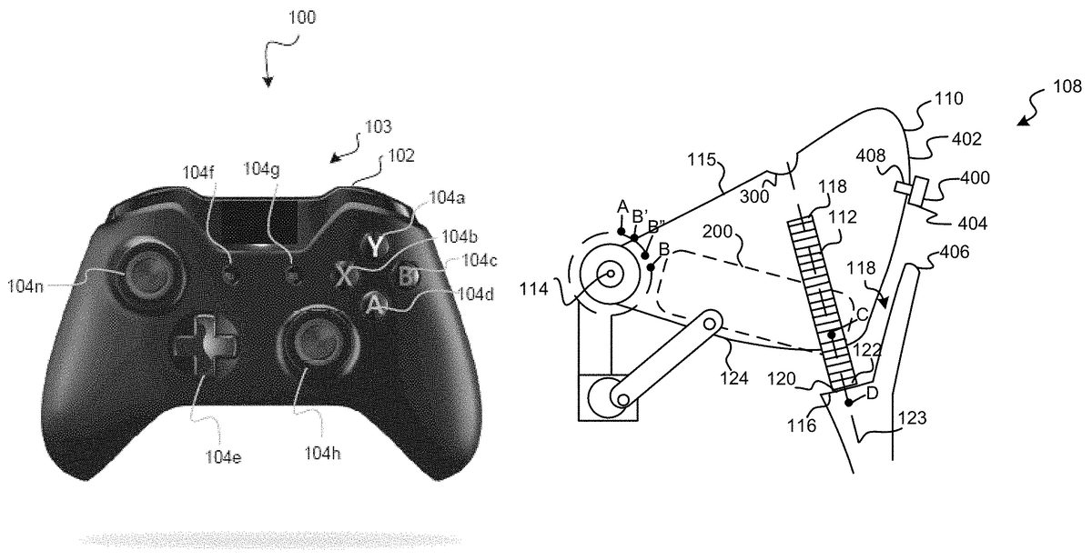
DETAILED DESCRIPTION The following detailed description is merely exemplary in nature and is not intended to limit the application and uses. Furthermore, there is no intention to be bound by any expressed or implied theory presented in the preceding technical field, background, brief summary or the following detailed description. As used herein, the term module refers to any hardware, software, firmware, electronic control component, processing logic, and/or processor device, individually or in any combination, including without limitation: application specific integrated circuit (ASIC), an electronic circuit, a processor (shared, dedicated, or group) and memory that executes one or more software or firmware programs, a combinational logic circuit, and/or other suitable components that provide the described functionality. With reference toFIGS. 1-2, a game controller100is shown that includes one or more trigger adjustment mechanisms in accordance with various embodiments. Although the figures shown herein depict an example with certain arrangements of elements, additional intervening elements, devices, features, or components may be present in an actual embodiments. It should also be understoodFIGS. 1-2are merely illustrative and may not be drawn to scale. As depicted inFIGS. 1-2, the game controller100generally includes a housing or a main body102and one or more actuator devices104a-104ncoupled thereto. The main body102may be configured of one or more pieces that are cooperatively configured to be held by a player or user of a game. The actuator devices104a-104ngenerate signals that are transmitted (e.g., wired or wirelessly) to a game console (not shown) and/or processed within the game controller100for game play. In various embodiments, a front side103of the game controller100(shown inFIG. 1) includes actuator devices104a-104nthat, when depressed or manipulated by a finger or thumb of the user, generate signals that indicate the depression of the button or a direction or degree in which the button was manipulated. For example, one or more of ...
DETAILED DESCRIPTION
The following detailed description is merely exemplary in nature and is not intended to limit the application and uses. Furthermore, there is no intention to be bound by any expressed or implied theory presented in the preceding technical field, background, brief summary or the following detailed description. As used herein, the term module refers to any hardware, software, firmware, electronic control component, processing logic, and/or processor device, individually or in any combination, including without limitation: application specific integrated circuit (ASIC), an electronic circuit, a processor (shared, dedicated, or group) and memory that executes one or more software or firmware programs, a combinational logic circuit, and/or other suitable components that provide the described functionality.
With reference toFIGS. 1-2, a game controller100is shown that includes one or more trigger adjustment mechanisms in accordance with various embodiments. Although the figures shown herein depict an example with certain arrangements of elements, additional intervening elements, devices, features, or components may be present in an actual embodiments. It should also be understoodFIGS. 1-2are merely illustrative and may not be drawn to scale.
As depicted inFIGS. 1-2, the game controller100generally includes a housing or a main body102and one or more actuator devices104a-104ncoupled thereto. The main body102may be configured of one or more pieces that are cooperatively configured to be held by a player or user of a game. The actuator devices104a-104ngenerate signals that are transmitted (e.g., wired or wirelessly) to a game console (not shown) and/or processed within the game controller100for game play.
In various embodiments, a front side103of the game controller100(shown inFIG. 1) includes actuator devices104a-104nthat, when depressed or manipulated by a finger or thumb of the user, generate signals that indicate the depression of the button or a direction or degree in which the button was manipulated. For example, one or more of the actuator devices104a-104gmay be digital devices (e.g., selection buttons, direction pads, etc.) that generate digital signals based on the depression of the respective actuator device104a-104g. In another example, one or more of the actuator devices104h-104nmay be analog devices (e.g., joysticks, etc.) that generate analog signals based on manipulation of the respective actuator device104h-104n.
A back side105of the game controller100(shown inFIG. 2) similarly includes actuator devices such as actuator devices106a-106nthat, when depressed or manipulated by a finger or thumb of the user, generate signals that indicate the depression of the respective actuator devices106a-106nor a direction or degree in which the respective actuator devices106a-106nwas manipulated. For example, one or more of the actuator devices106a-106bmay be digital devices (e.g., selection buttons, or other buttons) that generate digital signals based on the depression of the actuator device106a-106b.
In various embodiments, at least one of the actuator devices106a-106non the back side105of the game controller100is a trigger device108. The trigger device108includes a trigger body110that is depressible. The trigger device108may be an analog device that, when depressed generates an analog signal based on an amount or degree of the depression.
In various embodiments, the trigger device108includes an adjustable adjustment device that is internal to the main body102in accordance with various embodiments. In one example, the internal adjustable adjustment device adjusts a stop position of the trigger device108. For example, the adjustable adjustment device includes a surface area that contacts a surface area of the main body102when the trigger body110is moved or depressed a certain amount. The contact between the two surface areas stops the trigger body110from further movement.
As shown in more detail in the cross sectional side view ofFIG. 3(from the section plane Y ofFIG. 2), the trigger body110pivots along a pivot axis114which may be substantially perpendicular to one of the surfaces of the main body102(FIGS. 1 and 2). In one example, a first or top side115of the trigger body110moves or pivots between point A (a start point) and point B (a stop point). The adjustable adjustment device112is used to adjust the point B (the stop point) to B′ (an adjusted stop point).
For example, at least a portion of the adjustable adjustment device112extends from the trigger body110. When the trigger body110is depressed enough (as shown inFIG. 3), a surface area116of an inner side118of the main body102contacts a surface area120at a first end122of the adjustable adjustment mechanism112to stop the trigger body110from further depression.
Given the length of the adjustable adjustment device112shown, the surface area120of the adjustable adjustment device112(and thus, the contact position between the surface area116and the surface area120) may be adjusted to any number of positions between point C and point D along an axis123. Adjusting the position of the adjustable adjustment device112relative to the main body102causes the point B on the pivot axis114to be adjusted to point B′ as shown or any other position therebetween. It should be noted that although the surface area120and surface area116are described and illustrated herein, the contact between the adjustable adjustment mechanism112and the main body102is not limited to surface contact. Rather, the adjustable adjustment mechanism112may contact the main body102through point to point contact, or point to surface contact. Thus, the embodiments herein are merely exemplary. In various embodiments, when the adjustable adjustment device112is adjusted to point C or slightly above, the surface area120may not contact any surface area of the main body102, rather the trigger body110may pivot as if the adjustable adjustment device112were completely removed.
For exemplary purposes, the embodiments described and shown include a screw as the adjustable adjustment device112. As can be appreciated, in various other embodiments, the adjustable adjustment device112may be implemented as a plunger device, a screw or rod with a lever or arm attached, a screw or rod with any number of modifications or attachments, a rack and pinion, or any other element that is adjustable relative to the trigger body110to adjust the movement of the trigger device108.
In various embodiments, the adjustable adjustment device112extends from a receiver200that is housed within the trigger body110. The receiver200may be any suitable material or device capable of accommodating the adjustable adjustment device112in the requisite position. As shown inFIGS. 4-6and with continued reference toFIG. 3, an exemplary receiver200is a preformed part of plastic or other material that is inserted into the trigger body110. For example, the receiver200is sized such that it is insertable into a bore defined at a bottom124of the trigger body110(FIG. 3). In various embodiments, with reference toFIG. 4, the receiver200is substantially rectangular and includes a first or base portion202and a second or top portion204. The base portion202is substantially rectangular in shape with substantially flat sides and one or more rounded edges. The top portion204is substantially square-like in shape with at least one substantially flat side and somewhat rounded other sides. It should be noted that the size and shape of the receiver200described and illustrated herein is merely exemplary, as the receiver200can have any desired shape and size for receipt of the adjustable adjustment device112within the trigger body110.
The receiver200includes a throughbore206for receiving the adjustable adjustment device112. As shown in the back view of the receiver200inFIG. 4, the throughbore206begins at a first position in the base portion202. As shown in the side view of the receiver200inFIG. 5, the throughbore206extends through the receiver200at an angle that is offset X degrees from the horizontal or vertical axis. As shown in the front view of the receiver inFIG. 6, the opening206ends at a second position in the top portion204. Stated another way, the throughbore206is defined through the receiver200along an axis that is transverse to a longitudinal axis of the receiver200, and further, the throughbore206is defined through the receiver200so as to extend from a portion of the base portion202to the top portion204.
When the adjustable adjustment device112is implemented as a screw, the throughbore206of the receiver200includes one or more screw threads208that cooperate to matingly engage one or more screw threads associated with the screw. The screw threads208may be cut into the adjustment mechanism receptor200or may be part of a thread insert (not shown) that is inserted into the throughbore206in the receiver200.
With reference back toFIG. 3, the trigger body110optionally includes an opening300for accessing the adjustable adjustment device112. An adjustment tool (not shown) may be inserted into the opening300to access and move or adjust the adjustable adjustment device112from a second end126of the adjustable adjustment device112. Alternatively, the adjustable adjustment device112may be moved or adjusted from the first end122when, for example a portion of the main body102is removed.
With reference back toFIG. 2, in addition to the adjustable adjustment device112, in various embodiments, the trigger device108may further include a non-adjustable adjustment mechanism400. The non-adjustable adjustment mechanism400extends through a side402(FIG. 3) of the trigger body110to provide a non-adjustable stop position for the trigger device108. For example, with reference toFIGS. 2 and 3, the non-adjustable adjustment mechanism400includes a surface area404that contacts a surface area406of the main body102when the trigger body110is depressed a certain amount. The contact of the two surface areas404,406stops the trigger body110from further movement.
As shown in more detail in the cross sectional view ofFIG. 3, in various embodiments, when the trigger body110is depressed enough, the surface area404of the non-adjustable adjustment mechanism400that protrudes out from the trigger body110contacts the surface area406of the main body102to stop the trigger body110from further movement or depression. When the non-adjustable adjustment mechanism400is in place, the stop position of the top side115of the trigger body110is point B″. When the non-adjustable adjustment mechanism400is removed, the stop position of the top side115of the trigger body110is between point A and point B depending on whether the adjustable adjustment device112is in place.
For exemplary purposes, the embodiments described and shown implement the non-adjustable adjustment mechanism400as a screw that extends through a side402of the trigger body110. The screw is received in screw threads408defined in a portion of the trigger body110. The screw threads408may be cut into the trigger body110or may be part of a thread insert (not shown) that is inserted into an opening in the trigger body110. As can be appreciated, in various other embodiments, the non-adjustable adjustment mechanism400may be implemented at various locations of the trigger body110. For example, the non-adjustable adjustment mechanism400may extend through a side or sides of the trigger body110, so long as when moved or depressed, the non-adjustable adjustment mechanism400contacts a surface area of the main body102to limit movement of the trigger body110about the pivot axis. As can further be appreciated, in various embodiments, the non-adjustable adjustment mechanism400may be implemented as a rod inserted into holes, a screw screwed into threads, a protrusion, or any other mechanism for creating a contact surface that stops the movement of the trigger body110relative to the main body102.
While at least one exemplary embodiment has been presented in the foregoing detailed description, it should be appreciated that a vast number of variations exist. It should also be appreciated that the exemplary embodiment or exemplary embodiments are only examples, and are not intended to limit the scope, applicability, or configuration of the invention in any way. Rather, the foregoing detailed description will provide those skilled in the art with a convenient road map for implementing the exemplary embodiment or exemplary embodiments. It should be understood that various changes can be made in the function and arrangement of elements without departing from the scope of the invention as set forth in the appended claims and the legal equivalents thereof.
Claims
- A game controller, comprising: a main body;a trigger device having a trigger body coupled to the main body and that pivots along a pivotal axis relative to the main body;and a first adjustment device having a first surface that contacts a second surface of the main body at a first point of contact when the trigger body is moved, wherein the first adjustment device is movable along a first axis such that the first point of contact is adjusted along the first axis.
- The game controller of claim 1 , wherein the contact stops the trigger body from further movement.
- The game controller of claim 1 , wherein the first adjustment device is coupled to the trigger body.
- The game controller of claim 3 , wherein the first adjustment device comprises a screw.
- The game controller of claim 4 , wherein the trigger body includes a receiver that receives at least a portion of the adjustment device.
- The game controller of claim 5 , wherein the receiver includes a throughbore defining one or more threads for receiving the screw.
- The game controller of claim 5 , wherein the receiver includes a thread insert disposed within a throughbore for receiving the screw.
- The game controller of claim 5 , wherein the receiver includes a throughbore that extends along an axis that is transverse to a longitudinal axis of the receiver.
- The game controller of claim 8 , wherein the receiver includes a first portion and a second portion, and a throughbore that begins at the first portion and extends through the second portion.
- The game controller of claim 1 , further comprising a second adjustment device having a third surface that contacts a fourth surface of the main body at a second point of contact when the trigger body is moved.
- The game controller of claim 10 , wherein the contact stops the trigger body from further movement.
- The game controller of claim 10 , wherein the second adjustment device is coupled to the trigger body.
- The game controller of claim 10 , wherein the second adjustment device comprises a screw.
- A game controller, comprising: a main body;a trigger device having a trigger body is coupled to the main body and the trigger device moves along an axis;and a first adjustment device that is adjustable between a range of positions and that contacts the main body to limit the movement of the trigger body relative to the main body.
- The game controller of claim 14 , wherein the first adjustment device is coupled to the trigger body, and a portion of the trigger body is received within the main body.
- The game controller of claim 14 , wherein the first adjustment device comprises a screw, the trigger body comprises a receiver for receiving the screw.
- The game controller of claim 16 , wherein the receiver defines a throughbore that includes a thread insert or threads cut into the throughbore for receiving the screw.
- The game controller of claim 14 , further comprising: a second adjustment device that is fixed relative to the trigger body and that contacts the main body to limit the movement of the trigger body when the trigger body is moved a second amount.
- The game controller of claim 18 , wherein the second adjustment device is at least partially received in an opening defined in the trigger body.
- The game controller of claim 19 , wherein the second adjustment device comprises a screw.
Disclaimer: Data collected from the USPTO and may be malformed, incomplete, and/or otherwise inaccurate.