U.S. Pat. No. 9,901,813
SYSTEMS AND METHODS FOR ENHANCING TARGET ACQUISITION OF VIDEO GAMES
Issue DateMarch 8, 2016
Illustrative Figure
Abstract
The present invention relates to systems and methods for providing gaiming points for video gamers. In one embodiment, a gaiming system is coupled to a monitor of a computerized video gaming system. The gaiming system includes an energy source and a display. A gaiming command from the computerized video gaming system instructs the energy source to project a substantially narrow energy beam. The display has a gaiming target configured to scatter a portion of the narrow energy beam thereby generating a visible gaiming point substantially centered with respect to the monitor. In some embodiments, the intensity of the energy beam is selectable. It is also possible to contour the display to minimize unwanted scattering of the energy beam.
Description
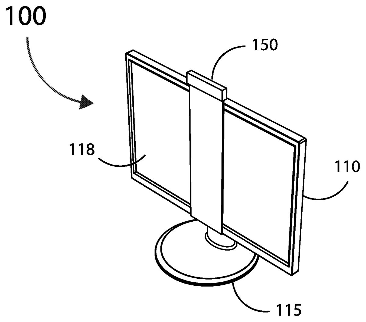
DETAILED DESCRIPTION The present invention will now be described in detail with reference to several embodiments thereof as illustrated in the accompanying drawings. In the following description, numerous specific details are set forth in order to provide a thorough understanding of embodiments of the present invention. It will be apparent, however, to one skilled in the art, that embodiments may be practiced without some or all of these specific details. In other instances, well known process steps and/or structures have not been described in detail in order to not unnecessarily obscure the present invention. The features and advantages of embodiments may be better understood with reference to the drawings and discussions that follow. Aspects, features and advantages of exemplary embodiments of the present invention will become better understood with regard to the following description in connection with the accompanying drawing(s). It should be apparent to those skilled in the art that the described embodiments of the present invention provided herein are illustrative only and not limiting, having been presented by way of example only. All features disclosed in this description may be replaced by alternative features serving the same or similar purpose, unless expressly stated otherwise. Therefore, numerous other embodiments of the modifications thereof are contemplated as falling within the scope of the present invention as defined herein and equivalents thereto. Hence, use of absolute and/or sequential terms, such as, for example, “will,” “will not,” “shall,” “shall not,” “must,” “must not,” “first,” “initially,” “next,” “subsequently,” “before,” “after,” “lastly,” and “finally,” are not meant to limit the scope of the present invention as the embodiments disclosed herein are merely exemplary. To facilitate discussion,FIGS. 1A, 1B & 1Care a perspective view, a front view and a cross-sectional view “A-A”, respectively, illustrating one embodiment100incorporating an aiming system150coupled to a video gaming system110having a ...
DETAILED DESCRIPTION
The present invention will now be described in detail with reference to several embodiments thereof as illustrated in the accompanying drawings. In the following description, numerous specific details are set forth in order to provide a thorough understanding of embodiments of the present invention. It will be apparent, however, to one skilled in the art, that embodiments may be practiced without some or all of these specific details. In other instances, well known process steps and/or structures have not been described in detail in order to not unnecessarily obscure the present invention. The features and advantages of embodiments may be better understood with reference to the drawings and discussions that follow.
Aspects, features and advantages of exemplary embodiments of the present invention will become better understood with regard to the following description in connection with the accompanying drawing(s). It should be apparent to those skilled in the art that the described embodiments of the present invention provided herein are illustrative only and not limiting, having been presented by way of example only. All features disclosed in this description may be replaced by alternative features serving the same or similar purpose, unless expressly stated otherwise. Therefore, numerous other embodiments of the modifications thereof are contemplated as falling within the scope of the present invention as defined herein and equivalents thereto. Hence, use of absolute and/or sequential terms, such as, for example, “will,” “will not,” “shall,” “shall not,” “must,” “must not,” “first,” “initially,” “next,” “subsequently,” “before,” “after,” “lastly,” and “finally,” are not meant to limit the scope of the present invention as the embodiments disclosed herein are merely exemplary.
To facilitate discussion,FIGS. 1A, 1B & 1Care a perspective view, a front view and a cross-sectional view “A-A”, respectively, illustrating one embodiment100incorporating an aiming system150coupled to a video gaming system110having a monitor118and a support base115, in accordance with the present invention. Note that gaming system110can be any one of a wide variety of computerized devices, including laptops, tablets, desktops, game consoles and televisions, i.e., gaming system110may or may not include a separate display monitor.
In this embodiment, as shown inFIG. 2A, aiming system150includes an enclosure252, a support bracket253, an energy source256, and a display254having an aiming point258. During operation, energy source256provides a narrow beam of visible light, defined by boundaries257a,257b(beam angle exaggerated for illustration and hence not drawn to scale). The beam of light is “scattered”, e.g., by a small hole drilled in display254, thereby providing a distinctly visible aiming point258for the video gamer(s).
aiming point258can include one or more of aiming reticles known to one skilled in the art. For example, aiming point258can incorporate a dot, a cross hair and/or a circle.
FIGS. 2B-2Dfurther illustrate the embodiment of aiming system150.FIGS. 2Bwith2C show a vertical lateral sectional view “B-B” of aiming system150, whileFIGS. 2Dtogether with2E &2F illustrate two additional sectional views “C-C” and “D-D” of aiming system150.
Alternate methods for illuminating aiming point258are possible. For example, in another embodiment, energy source256provides an invisible beam of electro-magnetic radiation capable of targeting and fluorescing aiming point258. In yet another embodiment, an energy source located on the side of the video monitor provides a horizontal beam of energy to the aiming point. It may also be possible to energize a visible aiming point using electro-magnetic induction, for example, by using a micro-induction coil coupled to a miniature incandescent light bulb. In some embodiments, aiming point258may also include a bioluminescent material that can react with the energy source256to enhance the intensity of aiming point258.
In order to accommodate a wide variety of video games, aiming system150may be configurable by the video-gaming system and/or the video gamer. In some embodiments, the intensity of the aiming point may be adjustable (statically or dynamically), the aiming point may flash, e.g., the aiming point intensity may be temporarily reduced when on video gamer's avatar is on the move or in scene with a darker background.
In some embodiments, energy source256is capable of producing a selectable spectrum of visible light, thereby significantly increasing the versatility of aiming system150, and providing superior gaming point visibility for a wider variety of video gaming scenarios.
Further, to be able to better interact with the video game, the aiming system150may be able to communicate directly with the video game system110via for example an API. In addition, the aiming system150may also (passively) measure the light intensity of a portion of the monitor of the video gaming system110, and adjusting the intensity of the aiming point accordingly.
Referring now to theFIGS. 3A-3B, 3C-3D, 3E-3F, 3G-3H and 3J-3K, respective pairs of front views and horizontal sectional views, several modifications, alone and in combination, can be made to the aiming system150ofFIG. 2Ato minimize edge refraction resulting from stray energy generated by energy source256.
For example,FIGS. 3A and 3B, a sectional view G-G, illustrate an embodiment of aiming system display310with aiming point314and angled side edges316&318. In addition,FIGS. 3C and 3D, sectional view H-H, illustrate another embodiment of aiming system display320with aiming point324and half-rounded side edges326&328, whileFIGS. 3E and 3F, a sectional view M-M, illustrate yet another embodiment of aiming system display330with aiming point334and quarter-rounded side edges336&338.
FIG. 3Gillustrates another embodiment of aiming system display340having an aiming point344. In this embodiment, as shown by sectional view N-N ofFIG. 3H, display340has a tapered cross-sectional profile thereby substantially reducing the thickness of the side edges346&348. In yet another embodiment as shown inFIGS. 3J and 3K, display350includes a curved cross-sectional profile which may be contoured to match the surface of a curved video gaming system monitor (not shown).
Many modifications and additions are possible. For example, aiming system can be modified to support multiple players, by providing additional aiming points, which may be illuminated by the same power source or by additional power source(s). In some embodiments, aiming system150can be temporarily and/or permanently attached to video gaming system110using one or more of a variety of techniques known to one skilled in the art, including hook-and-loop, mechanical fasteners such as screws and rivets, magnets, clamps, straps, elastic bands and adhesives including double-sided tape.
In some embodiments, energy source of the above described embodiment of aiming systems can be self-powered by a battery and/or solar-cell. In some embodiments, light source is powered externally via USB, or via front. In yet other embodiments, light source is collected from the environment, e.g., the power indicator of the monitor, or concentrated from ambient lighting source(s), natural and/or artificial.
The advantages of exemplary aiming systems of the present invention include the ability of the video gamer to quickly acquire/reacquire potential targets while on the move and thereafter. Hence, the ability to generate a user-selectable and highly visible aiming point aids video gamers, especially gamers who may be color-blind. As a result, the aiming systems of the present invention provides superior user-friendly, fun and/or unique experiences for video gamers.
While this invention has been described in terms of several embodiments, there are alterations, modifications, permutations, and substitute equivalents, which fall within the scope of this invention. Although sub-section titles have been provided to aid in the description of the invention, these titles are merely illustrative and are not intended to limit the scope of the present invention.
It should also be noted that there are many alternative ways of implementing the methods and apparatuses of the present invention. It is therefore intended that the following appended claims be interpreted as including all such alterations, modifications, permutations, and substitute equivalents as fall within the true spirit and scope of the present invention.
Claims
- In an aiming system, useful in association with a computerized video gaming system, a method of providing an aiming target, the method comprising: receiving an aiming command from a computerized video gaming system to illuminate an aiming target of an aiming system;and projecting a narrow planar energy beam at the aiming target located on an overlay of the aiming system, wherein the overlay is aligned with and located in front of a monitor of the video gaming system;and scattering the planar energy beam at the aiming target in a direction toward a user of the video gaming system thereby improving target acquisition for the user by illuminating the aiming target.
- The method of claim 1 further comprising: receiving a command to vary a size of the aiming target;and adjusting the size of the aiming target.
- The method of claim 1 further comprising: receiving a command to vary an intensity of the aiming target;and increasing or decreasing the intensity of the aiming target.
- The method of claim 1 further comprising: detecting an intensity change of the monitor;and increasing or decreasing the intensity of the aiming target in response to the intensity change of the monitor.
- The method of claim 1 further comprising: receiving a command to vary a viewing angle of the aiming target;and adjusting the viewing angle of the aiming target by adjusting an intensity of the aiming target.
- The method of claim 1 wherein the aiming target is at least one of an aiming dot, a cross-hair and a circle.
- An aiming system, useful in association with a computerized video gaming system, the aiming system comprising: an interface configured to receive an aiming command from a computerized video gaming system;an overlay configured to be aligned with and located in front of a monitor of the video gaming system;an energy source configured to project a substantially narrow planar energy beam along the overlay;and an aiming target proximate overlay, the aiming target configured to scatter a portion of the narrow energy beam towards a user of the video gaming system thereby improving target acquisition for the user by illuminating the aiming target.
- The aiming system of claim 7 wherein the interface is further configured to receive a command to vary at least one of aiming target size, intensity and viewing angle.
- The aiming system of claim 7 further comprising: a detector configured to detect an intensity change of the monitor;and wherein the energy source is further configured to increase or decrease the intensity of the aiming target in response to the intensity change of the monitor.
- The aiming system of claim 7 wherein the aiming target is at least one of an aiming dot, a cross-hair and a circle.
- The aiming system of claim 7 wherein the aiming target include at least one of a hole and an aiming pattern.
- The aiming system of claim 11 wherein the aiming target is machined or drilled.
- The aiming system of claim 11 wherein the aiming target is etched.
- The method of claim 1 wherein the aiming point is centered with respect to the monitor from a viewpoint of the user.
- The aiming system of claim 11 wherein the aiming target is centered with respect to the monitor from a viewpoint of the user.
- The aiming system of claim 7 wherein an edge of the overlay is contoured to minimize unwanted scattering of the energy beam.
- The aiming system of claim 7 wherein a profile of the overlay is contoured to minimize unwanted scattering of the energy beam.
- The aiming system of claim 7 wherein the aiming target is further configured to flash.
- The aiming system of claim 7 wherein the intensity of the aiming target is further configured to vary in intensity depending on a movement or a background of a scene.
Disclaimer: Data collected from the USPTO and may be malformed, incomplete, and/or otherwise inaccurate.