U.S. Pat. No. 9,873,048
METHOD AND SYSTEM FOR ADJUSTING A FIELD OF VIEW REGION IN A VIRTUAL SPACE
AssigneeCOLOPL, INC.
Issue DateFebruary 10, 2017
Illustrative Figure
Abstract
A method of adjusting a field of view of a user for a head mounted display (HMD) includes defining a virtual camera for specifying an image of the field of view in a virtual space. In response to updating an image of the field of view by changing a position of the virtual camera without synchronization with the movement of the HMD, the position of the virtual camera is moved in a movement direction of a player object to move the player object into a predetermined range of the field of view. The field of view is sectioned into a non-tracking region defined by the predetermined range, a near tracking region, and a far tracking region. A relief region is between the non-tracking region and the far tracking region. Movement of the player object is based on a location of the player object within the field-of view region.
Description
DETAILED DESCRIPTION First, contents of at least one embodiment of this disclosure are described in a list. A method and system for adjusting a field of view region in a virtual space according to at least one embodiment of this disclosure have the following configurations. (Item 1) A method of adjusting a field of view region according to at least one embodiment of this disclosure is a method of adjusting a field of view region of a user in a virtual space provided to a head mounted display of a non-transmissive type. The method includes defining a virtual camera for specifying an image of the field of view that is visually recognizable by the user in a virtual space image forming the virtual space. The method further includes displaying the image of the field of view on the head mounted display. The method further includes moving a player object arranged in the virtual space based on a user action. The method further includes updating the image of the field of view by changing a direction of the virtual camera in synchronization with a movement of the head mounted display. The method further includes moving, when the image of the field of view is updated by changing a position of the virtual camera without synchronization with the movement of the head mounted display, the position of the virtual camera in a movement direction of the player object such that the player object moved in the field of view region is located within a predetermined range of the field of view region. With this configuration, the image of the field of view is updated by changing the position of the virtual camera in accordance with the movement of the player object, and hence the user's sense of presence is improved, at least ...
DETAILED DESCRIPTION
First, contents of at least one embodiment of this disclosure are described in a list. A method and system for adjusting a field of view region in a virtual space according to at least one embodiment of this disclosure have the following configurations.
(Item 1)
A method of adjusting a field of view region according to at least one embodiment of this disclosure is a method of adjusting a field of view region of a user in a virtual space provided to a head mounted display of a non-transmissive type. The method includes defining a virtual camera for specifying an image of the field of view that is visually recognizable by the user in a virtual space image forming the virtual space. The method further includes displaying the image of the field of view on the head mounted display. The method further includes moving a player object arranged in the virtual space based on a user action. The method further includes updating the image of the field of view by changing a direction of the virtual camera in synchronization with a movement of the head mounted display. The method further includes moving, when the image of the field of view is updated by changing a position of the virtual camera without synchronization with the movement of the head mounted display, the position of the virtual camera in a movement direction of the player object such that the player object moved in the field of view region is located within a predetermined range of the field of view region.
With this configuration, the image of the field of view is updated by changing the position of the virtual camera in accordance with the movement of the player object, and hence the user's sense of presence is improved, at least in some instances. Further, the direction of the virtual camera is changed in synchronization with the movement of the head mounted display, and the change of the direction is predictable by the user. Therefore, a VR sickness of the user is reduced, at least in some instances.
(Item 2)
In at least one embodiment, the position of the virtual camera be moved at a speed lower than a movement speed of the player object.
By moving the position of the virtual camera at a speed slower than the player object, the VR sickness is suppressed.
(Item 3)
In at least one embodiment, the field of view region be sectioned into a non-tracking region being the predetermined range, a near tracking region on a near side of the virtual camera with respect to the non-tracking region, and a far tracking region on a far side of the virtual camera with respect to the non-tracking region.
In at least one embodiment, when the player object is moved within the non-tracking region, the position of the virtual camera is prevented from being moved in the movement direction of the player object. When the player object is moved from the non-tracking region to one of the near tracking region and the far tracking region, the position of the virtual camera is moved such that the player object is located in the non-tracking region.
With this configuration, the tracking control of the virtual camera is appropriately performed when the player object is moved to the near tracking region or the far tracking region, but the virtual camera is not subjected to tracking control when the player object is moved within the non-tracking region. Therefore, a VR sickness due to an unexpected motion of the image of the field of view can be suppressed.
(Item 4)
In at least one embodiment, control be performed such that a movement speed of the position of the virtual camera when the player object is moved to the near tracking region is lower than a movement speed of the position of the virtual camera when the player object is moved to the far tracking region.
Backward movement of the virtual camera (movement of the position of the virtual camera based on the player object moved to the near tracking region) tends to cause VR sickness. Therefore, when the movement speed in the backward movement is decreased as compared to the case of forward movement (movement of the position of the virtual camera based on the player object moved to the far tracking region), the VR sickness can be further reduced.
(Item 5)
In at least one embodiment, when the player object is moved within one of the near tracking region and the far tracking region, the position of the virtual camera be moved such that the player object is located in the non-tracking region.
When the player object is moved within the near tracking region or within the far tracking region, by performing tracking control such that the player object is located in the non-tracking region instead of moving the position of the virtual camera directly in synchronization with the movement of the player object, an unexpected motion of the image is suppressed, in at least some instances.
(Item 6)
In at least one embodiment, a relief region be provided between the non-tracking region and the far tracking region. In at least one embodiment, in a case where the player object is moved from the non-tracking region to the far tracking region, the moving of the position of the virtual camera be initiated when the player object is located at a boundary between the far tracking region and the relief region, and the moving of the position of the virtual camera be ended when the player object is located at a boundary between the relief region and the non-tracking region.
When the relief region is provided, tracking control of the virtual camera is prevented from being excessively sensitive, and excess change of the image of the field of view is suppressed, in at least some instances.
(Item 7)
In at least one embodiment, control is performed such that, when the player object is moved outside of the field of view region, the position of the virtual camera is prevented from being moved.
(Item 8)
In at least one embodiment, when the player object is moved outside of the field of view region, and then the player object enters the field of view region again due to the updating of the image of the field of view in synchronization with the movement of the head mounted display, the position of the virtual camera be moved such that the player object is located in the non-tracking region.
With those configurations, the initiative of the operation of tracking the player object by the virtual camera is left to the user, and hence the sense of presence in the game is improved, in at least some instances.
(Item 9)
A system according to at least one embodiment of this disclosure is a system for executing the method of any one of Items 1 to 8.
With this configuration, the program capable of reducing the VR sickness while improving the sense of presence is provided.
Examples of a method of adjusting a field of view region in a virtual space provided to an HMD and a system for executing the method according to at least one embodiment of this disclosure are described below with reference to the drawings. The virtual space is herein a three-dimensional virtual space, but this disclosure is not necessarily limited thereto. This disclosure is not limited to those examples, and is defined by the appended claims. One of ordinary skill in the art would understand that this disclosure includes all modifications within the appended claims and the equivalents thereof. In the following description, like elements are denoted by like reference symbols in the description of the drawings, and redundant description thereof is omitted.
FIG. 1is a schematic view of a configuration of an HMD system using an HMD according to at least one embodiment.FIG. 2is a block diagram of a hardware configuration of a control circuit unit included in the HMD system ofFIG. 1.
As illustrated inFIG. 1, an HMD system100includes an HMD110that is wearable on a head of a user U, a control circuit unit120, a movement sensor130, and an external controller140.
The HMD110includes a display unit112, an HMD sensor114, and headphones116. In at least one embodiment, the headphones116are not included in the HMD110, and a speaker and headphones that are independent of the HMD110may be used.
The display unit112includes a non-transmissive (or partially transmissive) display device configured to completely cover a field of view (visual field) of the user U wearing the HMD110. With this, the user U can see only a screen displayed on the display unit112. That is, the user U loses (or partially loses) the visual field of the external world, and hence the user U can be immersed in a virtual space displayed on the display unit112by an application executed by the control circuit unit120.
The HMD sensor114is mounted near the display unit112of the HMD110. The HMD sensor114includes at least one of a geomagnetic sensor, an acceleration sensor, or an inclination (angular velocity or gyro) sensor, and can detect various movements of the HMD110worn on the head of the user U.
The movement sensor130includes, for example, a position tracking camera (position sensor). The movement sensor130is connected to the control circuit unit120so as to be capable of communicating to/from the control circuit unit120, and has a function of detecting information relating to positions or inclinations of a plurality of detection points (not shown) provided on the HMD110. The detection points are, for example, light emitting portions configured to emit infrared light or visible light. The position tracking camera serving as the movement sensor130includes an infrared sensor or a plurality of optical cameras. The control circuit unit120is configured to acquire information of the position of the HMD110from the movement sensor130, to thereby accurately associate a position of a virtual camera in the virtual space with the position of the user U wearing the HMD110in the real space.
In at least one embodiment, the HMD system includes at least one of the HMD sensor114or the movement sensor130for detecting the movement of the HMD110. When the movement of the HMD110can be sufficiently detected with use of any one of the sensors, the other sensor may be omitted, in at least one embodiment.
The control circuit unit120may be configured as hardware (computers such as a personal computer and a server computer connected via a network) different from the HMD110. As inFIG. 2, the control circuit unit120includes a processing circuit121, a memory122, a storage medium123, an input/output interface124, and a communication interface125, which are connected to each other via a communication bus serving as a data transmission path. The control circuit unit120may be mounted inside the HMD110. Further, in at least one embodiment, a part of the functions of the control circuit unit120may be mounted on the HMD110, and the remaining functions may be mounted on hardware different from the HMD110.
The processing circuit121includes various processors such as a central processing unit (CPU), a micro-processing unit (MPU), and a graphics processing unit (GPU), and has a function of controlling the entire control circuit unit120and HMD system100.
The memory122includes volatile storage devices such as a read only memory (ROM) and a random access memory (RAM), and is configured to store programs to be used by the processing circuit121and control data such as calculation parameters.
The storage medium123includes non-volatile storage devices such as a flash memory and a hard disk drive (HDD), and is configured to store user authentication programs, game programs including data relating to various images and objects, and other programs. The storage medium123may further construct a database including tables for managing various kinds of data.
The input/output interface124includes various connection terminals such as a universal serial bus (USB) terminal, a digital visual interface (DVI) terminal, and a high-definition multimedia interface (HDMI)® terminal, and various processing circuits for wireless connection. The input/output interface124is configured to connect the HMD110, the movement sensor130, the external controller140, and the like to each other.
The communication interface125includes various wire connection terminals for communicating to/from an external device via a network NW, and various processing circuits for wireless connection. The communication interface125is configured to adapt to various communication standards for communication via a local area network (LAN) or the Internet.
The control circuit unit120is configured to execute an application stored in the memory122or the storage medium123, to thereby present a virtual space on the display unit112of the HMD110. With this, the HMD110can execute an operation for immersing the user U in a three-dimensional virtual space (VR space).
The external controller140is a user terminal, and is, for example, a game console. In addition, in at least one embodiment, the external controller140is a portable device including a touch display, for example, a smart phone, a personal digital assistant (PDA), a tablet computer, or a notebook personal computer (PC). In at least one embodiment, the external controller140includes a central processing unit (CPU), a main storage, an auxiliary storage, a transmitting/receiving unit, a display unit, and an input unit, which are connected to each other via a bus. The user U wearing the HMD110performs input, for example, touch operation, to the external controller140, to thereby give various operation instructions to the virtual space.
Next, with reference toFIG. 3, a method of acquiring information relating to the position and the inclination (direction of visual axis) of the HMD110is described. The information relating to the position (including direction and inclination) of the HMD110, which is based on the movement of the head of the user U wearing the HMD110, is detectable by the movement sensor130and/or the HMD sensor114mounted on the HMD110. As inFIG. 3, a three dimensional coordinate system (XYZ coordinates) is defined about the head of the user U wearing the HMD110. A perpendicular direction in which the user U stands upright is defined as a Y axis, a direction being orthogonal to the Y axis and connecting between the user U and the center of the display unit112is defined as a Z axis, and a direction orthogonal to the Y axis and the Z axis is defined as an X axis. The movement sensor130and/or the HMD sensor114are/is configured to detect angles about the respective axes (that is, inclination determined by a yaw angle representing rotation about the Y axis, a pitch angle representing rotation about the X axis, and a roll angle representing rotation about the Z axis), and the control circuit unit120is configured to determine angle (inclination) information data for controlling the virtual camera that defines the visual field information based on the temporal change of the angles.
FIG. 4Ais a YZ plane diagram of an example of a virtual space and a virtual camera, andFIG. 4Bis an XZ plane diagram of an example of the virtual space and the virtual camera.
As inFIG. 4AandFIG. 4B, a virtual camera300is arranged inside a celestial-sphere virtual space200. In at least one example, the virtual camera300is arranged at the center of the virtual space200as viewed from the top. A field of view region (visual region that is visually recognizable by the user)210is defined based on the position and the direction of the virtual camera300in the virtual space200. The field of view region210is determined based on a reference sight line L of the virtual camera300. The field of view region210has a first region210A defined as a range including a polar angle α with the reference sight line L being the center in the YZ plane inFIG. 4A, and a second region210B defined as a range including an azimuth β with the reference sight line L being the center in the XZ plane inFIG. 4B. An image of the field of view that is visually recognizable by the user is generated based on the field of view region210including the first region210A and the second region210B. The image of the field of view includes two two-dimensional images for right and left eyes. The two-dimensional images for the right and left eyes are superimposed on the display unit112of the HMD110, and thus the image of the field of view is provided to the user as a three-dimensional image.
The movement of the position and the direction of the virtual camera300is controllable based on the input from the movement sensor130or the HMD sensor114and/or the input from the external controller140. In at least one embodiment, the direction of the virtual camera300is changed based on the input from the movement sensor130or the HMD sensor114(that is, in synchronization with the movement of the head of the user wearing the HMD110), and the position of the virtual camera is changed based on the input from the external controller140(that is, without synchronization with the movement of the HMD110).
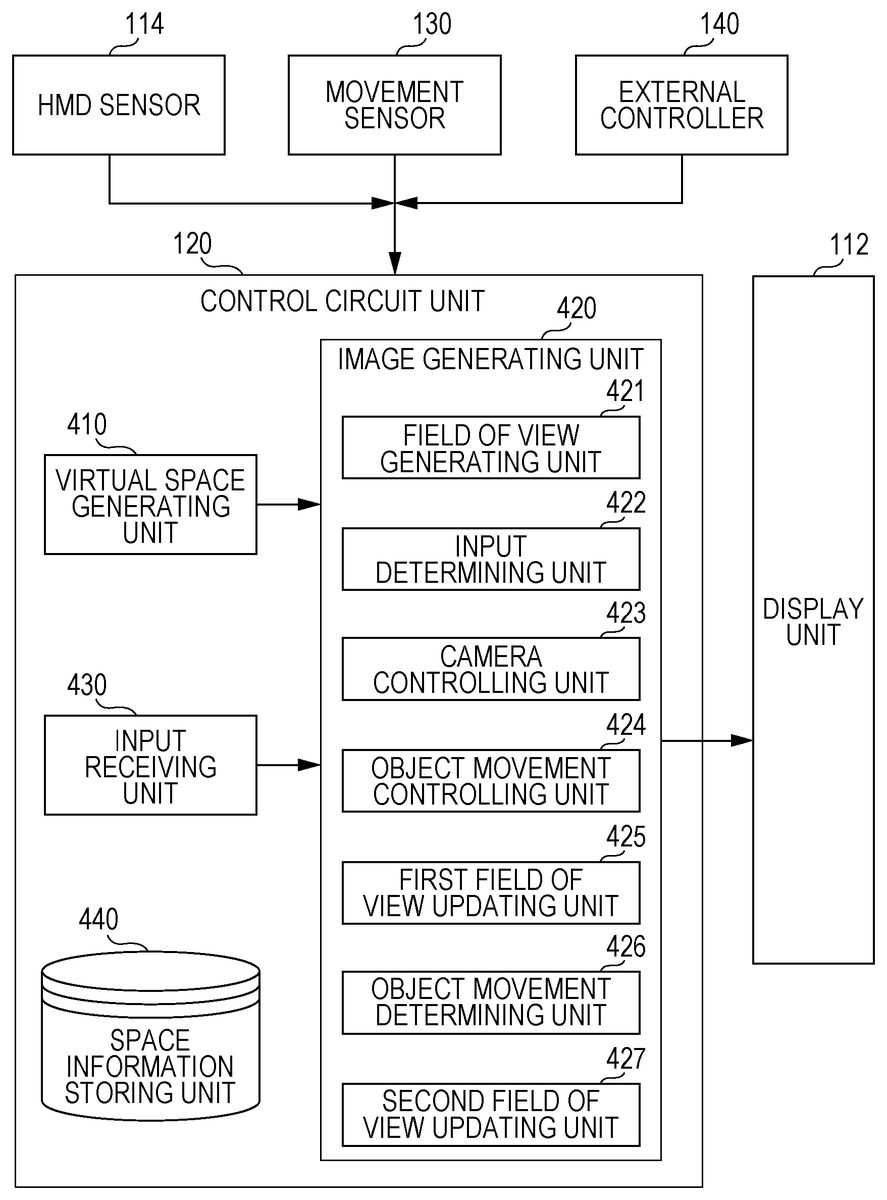
FIG. 5is a block diagram of a function of the control circuit unit120, for achieving the configuration of this embodiment.FIG. 6is a flow chart of a method of processing in the HMD system according to at least one embodiment.
As illustrated inFIG. 5, the control circuit unit120includes a virtual space generating unit410, an image generating unit420, an input receiving unit430, and a space information storing unit440. The image generating unit420includes a field of view generating unit421, an input determining unit422, a camera controlling unit423, an object movement controlling unit424, a first field of view updating unit425, an object movement determining unit426, and a second field of view updating unit427.
As inFIG. 6, first, the virtual space generating unit410refers to the space information storing unit440to generate the celestial-sphere virtual space200in which the user is immersed (Step S501). As inFIG. 7AandFIG. 7B, in the virtual space200, there are arranged, together with the virtual camera300, game objects including a player object P1that is an own player and a player object P2that is an opponent player in a match-up sports game, for example, a tennis game. In the example ofFIG. 7A, for example, the position of the virtual camera300is defined such that the player object P1is arranged at a predetermined field of view center point C located on the reference sight line L of the virtual camera300.
Next, in the image generating unit420, the field of view generating unit421specifies the field of view region210that is visually recognizable by the user based on the position and the direction of the virtual camera300in the virtual space200(Step S502). As illustrated inFIG. 7A, the field of view region210is sectioned into a band-like non-tracking region211extending laterally so as to include the field of view center point C located on the reference sight line L, a near tracking region212on the near side of the virtual camera300with respect to the non-tracking region211, and a far tracking region213on the far side of the virtual camera300with respect to the non-tracking region211. As inFIG. 7A, for example, when the user wearing the HMD110is looking at the player object P1, the position and the direction of the virtual camera300are defined such that the player object P1is located near the field of view center point C in the non-tracking region211.
Then, the field of view generating unit421outputs, as a result of executing Step S502, information relating to the display mode of the field of view based on the field of view region210of the virtual camera300to the HMD110. The HMD110receives this information to cause the display unit112to display the image of the field of view (Step S503).
Next, the input receiving unit430receives the input from the HMD sensor114, the movement sensor130, and the external controller140as input for moving the position and/or the direction of the virtual camera300(Step S504). Depending on the content to be executed using the VR space, in some cases, the virtual camera300may automatically move in the virtual space200to change the field of view region210under a state in which there is no movement of the HMD110or no input from the external controller140.
Next, in the image generating unit420, the input determining unit422determines whether the virtual camera300is moved in synchronization with the movement of the HMD110or without synchronization with the movement of the HMD110(Step S505). That is, the input determining unit422determines whether the input in Step S504is input from the HMD sensor114and/or the movement sensor130or input from the external controller140.
When it is determined that the input in Step S504is input for moving the virtual camera300in synchronization with the movement of the HMD110(that is, input from the HMD sensor114and/or the movement sensor130) (“Yes” from Step S505), in the image generating unit420, the camera controlling unit423specifies a new direction of the virtual camera300based on the input from the HMD sensor114and/or the movement sensor130(Step S506). Then, in the image generating unit420, the first field of view updating unit424specifies a new image of the field of view based on the specified new direction of the virtual camera300, and generates a image of the field of view to be updated based on the change of the direction of the virtual camera300(Step S507). As described above, when the movement of the virtual camera300is controlled in synchronization with the movement of the HMD110, the movement of the HMD110in the real space is associated with the movement of the virtual camera300in the virtual space200such that the reference sight line L of the virtual camera300corresponds to the Z-axis direction (seeFIG. 3) of the three-dimensional coordinate system of the HMD110. In at least one example inFIG. 7A, when the user moves his or her head so as to direct his or her sight line toward another game object (for example, the player object P2) from the player object P1, as inFIG. 7B, the direction of the virtual camera300is changed such that the player object P2is located on the reference sight line L in synchronization with the movement of the HMD110. With this, the field of view region210is changed, and the image of the field of view that is visually recognizable by the user is updated. As described above, the image of the field of view may be updated by changing the direction of the virtual camera300in synchronization with the movement of the HMD110. At this time, the position of the virtual camera300is defined such that the player object P1is located in the non-tracking region211when the player object P1is the user's player and is included in the field of view region210even after the direction of the virtual camera300is changed in synchronization with the movement of the HMD110. The positional adjustment of the virtual camera300when the player object P1gets out of the field of view region210is described later.
Next, the first field of view updating unit424outputs, as a result of executing Step S507, information relating to the display mode of the image of the field of view to be updated by changing the direction of the virtual camera300to the HMD110. The HMD110receives this information to update the image of the field of view to be displayed on the display unit112(Step S508). Then, the processing returns to Step S504.
On the other hand, when, in Step S505, the input in Step S504is determined to be an input for moving the virtual camera300without synchronization with the movement of the HMD110(that is, input from the external controller140) (“No” from Step S505), in the image generating unit420, the object movement controlling unit425moves the player object P1based on the input from the external controller140(Step S509). Specifically, the object movement controlling unit425outputs the information relating to the movement of the player object P1to the HMD110, and the HMD110moves the player object P1displayed on the display unit112based on the received information. In some cases, the player object P1may automatically move in the virtual space200under a state in which there is no input to the external controller140.
Next, in the image generating unit420, the object movement determining unit426specifies the position of the movement destination of the player object P1to determine whether or not the position of the movement destination is within the non-tracking region211(Step S510). When the movement destination of the player object P1is determined to be within the non-tracking region211(“Yes” from Step S510), the image generating unit420does not move the position of the virtual camera300, and the processing returns to Step S504. As described above, the virtual camera300is not subjected to tracking control when the player object P1is moved within the non-tracking region211, and hence the risk of VR sickness due to an unexpected motion of the image of the field of view is reduced, in at least some instances.
On the other hand, when the movement destination of the player object P1is determined to be outside of the non-tracking region211(No in Step S510), the object movement determining unit426determines whether or not the movement destination of the player object P1is within the near tracking region212or the far tracking region213(Step S511).
When the movement destination of the player object P1is determined to be within the near tracking region212or the far tracking region213(“Yes” from Step S511), the camera controlling unit423specifies a new position of the virtual camera300based on the position of the movement destination of the player object P1(Step S512). Then, in the image generating unit420, the second field of view updating unit427specifies a new image of the field of view based on the specified new position of the virtual camera300, and generates a image of the field of view to be updated based on the change of the position of the virtual camera300(Step S513). As described above, when the movement of the virtual camera300is controlled without synchronization with the movement of the HMD110, the position of the virtual camera300is moved so as to track the movement of the player object P1.
For example, as inFIG. 8A, when the player object P1is moved from the non-tracking region211to the far tracking region213based on the input from the external controller140, the camera controlling unit423moves the position of the virtual camera300in the movement direction of the player object P1such that the moved player object P1is located in the non-tracking region211. That is, as illustrated inFIG. 8B, the camera controlling unit423moves the virtual camera300forward until the player object P1is located in the non-tracking region211. In detail, the camera controlling unit423specifies the movement-destination direction of the player object P1, and moves the virtual camera300from the position indicated inFIG. 8A(broken-line position ofFIG. 8B) in the movement-destination direction of the player object P1such that a distance between the movement destination and the position of the virtual camera300falls within a predetermined range. The movement destination of the player object P1is specified based on an angle θ of a movement-destination direction D of the player object P1with respect to the reference sight line L, and the virtual camera300is moved obliquely while maintaining this angle θ such that the player object P1falls within the non-tracking region211. That is, when the player object P1is moved based on the input from the external controller140, tracking control is performed such that the position of the virtual camera300is changed without changing the direction of the virtual camera300. The movement destination of the player object P1is specified in each frame (or within a defined number of frames), and the movement direction of the virtual camera300is also updated in each frame (or within the defined number of frames). The camera controlling unit423may move the position of the virtual camera300such that, as inFIG. 8C, at least a part of the player object P1enters the non-tracking region211instead of moving the position of the virtual camera300such that the entire player object P1falls within the non-tracking region211. Further, as inFIG. 9A, when the player object P1is moved from the non-tracking region211to the near tracking region212based on the input from the external controller140, as inFIG. 9B, the camera controlling unit423moves the virtual camera300obliquely backward from the current camera position along the movement-destination direction D of the player object P1until the player object P1is located in the non-tracking region211.
When the position of the virtual camera300is moved so as to track the movement of the player object P1as described above, the camera controlling unit423moves the position of the virtual camera300at a speed lower than the movement speed of the player object P1, in at least one embodiment. The VR sickness may be suppressed when the position of the virtual camera300is moved slower than the player object P1. Further, in at least one embodiment, the camera controlling unit423performs control such that the movement speed of the position of the virtual camera300when the player object P1is moved to the near tracking region212is lower than the movement speed of the position of the virtual camera300when the player object P1is moved to the far tracking region213. Backward movement of the virtual camera300tends to cause VR sickness, and hence, when the movement speed in the backward movement is decreased as compared to the case of forward movement, the VR sickness is further reduced, at least on some instances.
Next, the second field of view updating unit427outputs, as a result of executing Step S513, information relating to the display mode of the image of the field of view to be updated to the HMD110. The HMD110causes the display unit112to display the updated image of the field of view (Step S514). Then, the processing returns to Step S504.
On the other hand, when the movement destination of the player object P1is determined to be outside of the near tracking region212and the far tracking region213, that is, when the movement destination of the player object P1is determined to be outside of the field of view region210as inFIG. 10A(No in Step S511), the processing returns to Step S504without performing the movement of the position of the virtual camera300. As inFIG. 10B, when the user shifts his or her sight line to the player object P1after the player object P1is moved outside of the field of view region210, the image of the field of view is updated in synchronization with the movement of the HMD110. When the player object P1enters the field of view region210again with this update of the image of the field of view, as inFIG. 10C, the position of the virtual camera300is controlled such that the player object P1is located in the non-tracking region211. When tracking by the virtual camera300is performed without synchronization with the movement of the HMD110even when the movement destination of the player object P1is outside of the field of view region210, the sense of presence may be reduced. Therefore, in at least one embodiment, the initiative of the operation of tracking the player object P1by the virtual camera300is left to the user.
As described above, in at least one embodiment, the method includes a step of updating the image of the field of view by changing the direction of the virtual camera300in synchronization with the movement of the HMD110, and a step of, when the image of the field of view is updated by changing the position of the virtual camera300without synchronization with the movement of the HMD110, moving the position of the virtual camera300in the movement direction of the player object P1such that the player object P1moved in the field of view region210based on a user action is located in the non-tracking region211. With this configuration, the image of the field of view is updated by changing the position of the virtual camera300in accordance with the movement of the player object P1, and hence the user's sense of presence is improved, at least in some instances. Further, the direction of the virtual camera300is changed in synchronization with the movement of the HMD110, and this change of the direction is predictable to the user. Therefore, a VR sickness of the user is reduced, at least in some instances.
As illustrated inFIG. 11A, when the player object P1is moved within the far tracking region213(or within the near tracking region212), in at least one embodiment, the position of the virtual camera300is moved such that the player object P1is located in the non-tracking region211as inFIG. 11Binstead of moving the position of the virtual camera300directly in synchronization with the movement of the player object P1. When the player object P1is moved within the far tracking region213or within the near tracking region212, the position of the virtual camera300is controlled such that the player object P1is basically located in the non-tracking region211. Thus, an unexpected motion of an image is suppressed.
Further, as inFIG. 12A, in the field of view region210, a relief region (buffer region)214may be provided between the non-tracking region211and the far tracking region213. In this case, when the player object P1is moved from the non-tracking region211toward the far tracking region213, as inFIG. 12A, the position of the virtual camera300is prevented from being moved when the player object P1reaches the boundary between the non-tracking region211and the relief region214, and, as illustrated inFIG. 12B, the movement of the position of the virtual camera300is initiated when the player object P1reaches the boundary between the relief region214and the far tracking region213. Then, when the position of the virtual camera300is moved, and thus, as inFIG. 12A, the player object P1reaches the boundary between the relief region214and the non-tracking region211again, the movement of the position of the virtual camera300stops. As described above, when the relief region214is provided so as to delay-control the tracking movement of the virtual camera300, tracking control of the virtual camera300is prevented from being excessively sensitive, and excess change of the image of the field of view is suppressed, at least in some instances.
In the above-mentioned at least one embodiment, the example in which the tracking regions212and213and the non-tracking region211are defined based on the reference sight line L is described, but this disclosure is not limited thereto. For example, in at least one embodiment, the tracking regions212and213and the non-tracking region211may be defined based on the positional relationship between the virtual camera300and the player object P1. In this case, the player object P1may be arranged at a predetermined distance from the virtual camera300.
The above-mentioned embodiments are merely examples for facilitating an understanding of this disclosure, and does not serve to limit an interpretation of this disclosure. One of ordinary skill in the art would understand that this disclosure can be changed and modified without departing from the gist of this disclosure, and that this disclosure includes equivalents thereof.
Claims
- A method comprising: defining a virtual space;defining a virtual camera for specifying an image of a field of view of the virtual space, that is visually recognizable by a user;displaying the image of the field of view on a head mounted display;moving a player object arranged in the virtual space based on a user action;updating the image of the field of view by changing a direction of the virtual camera in synchronization with a movement of the head mounted display;and updating the image of the field of view by changing a position of the virtual camera without synchronization with the movement of the head mounted display by moving the position of the virtual camera such that the player object is located within a predetermined range of a field of view region of the virtual camera, wherein the field of view region is sectioned into a non-tracking region defined by the predetermined range, a near tracking region on a near side of the virtual camera with respect to the non-tracking region, and a far tracking region on a far side of the virtual camera with respect to the non-tracking region, providing a relief region between the non-tracking region and the far tracking region, and wherein, in response to the player object moving from the non-tracking region to the far tracking region, the position of the virtual camera begins moving in response to the player object being located at a boundary between the far tracking region and the relief region, and the virtual camera stops moving in response to the player object being located at a boundary between the relief region and the non-tracking region.
- The method according to claim 1 , wherein the virtual camera is moved at a speed lower than a movement speed of the player object.
- The method according to claim 1 , wherein, in response to moving the player object within the non-tracking region, the virtual camera is prevented from being moved in the movement direction of the player object, and in response to moving the player object from the non-tracking region to one of the near tracking region or the far tracking region, the virtual camera is moved such that the player object is located in the non-tracking region.
- The method according to claim 3 , further comprising controlling a movement speed of the virtual camera in response to moving the player object to the near tracking region being lower than a movement speed of the virtual camera in response to moving the player object to the far tracking region.
- The method according to claim 3 , wherein, in response to moving the player object within one of the near tracking region or the far tracking region, the virtual camera is moved such that the player object is located in the non-tracking region.
- The method according to claim 1 , further comprising preventing the virtual camera from moving in response to moving the player object outside of the field of view region.
- The method according to claim 6 , wherein, in response to moving the player object outside of the field of view region and then the player object entering the field of view region again due to the updating of the image of the field of view in synchronization with the movement of the head mounted display, the virtual camera is moved such that the player object is located in the non-tracking region.
- The method according to claim 1 , wherein the near tracking region, non-tracking region, relief region, and far tracking region are contiguously arranged in this order in the virtual space with the near tracking region being closest to the virtual camera.
- The method according to claim 1 , wherein the field of view does not include the relief region, and the near tracking region, non-tracking region, and far tracking region are contiguously arranged in this order in the virtual space with the near tracking region being closest to the virtual camera.
- A system for adjusting a field of view region of a user in a virtual space for a head mounted display, the system comprising: a non-transitory computer readable medium configured to store instructions;and a processor connected to the non-transitory computer readable medium, wherein the processor is configured to execute the instructions for: defining a virtual space defining a virtual camera for specifying an image of a field of view of the virtual space that is visually recognizable by a user;generating instructions for displaying the image of the field of view on a head mounted display;moving a player object arranged in the virtual space based on a user action;updating the image of the field of view by changing a direction of the virtual camera in synchronization with a movement of the head mounted display;and updating the image of the field of view by changing a position of the virtual camera without synchronization with the movement of the head mounted display, by moving the position of the virtual camera such that the player object is located within a predetermined range of a field of view region of the virtual camera in response to the player object being located within the field of view, wherein the field of view region is sectioned into a non-tracking region defined by the predetermined range, a near tracking region on a near side of the virtual camera with respect to the non-tracking region, and a far tracking region on a far side of the virtual camera with respect to the non-tracking region, providing a relief region between the non-tracking region and the far tracking region, and wherein, in response to the player object moving from the non-tracking region to the far tracking region, the position of the virtual camera begins moving in response to the player object being located at a boundary between the far tracking region and the relief region, and the position of the virtual camera stops moving in response to the player object being located at a boundary between the relief region and the non-tracking region.
Disclaimer: Data collected from the USPTO and may be malformed, incomplete, and/or otherwise inaccurate.