U.S. Pat. No. 9,855,500
SYSTEM AND METHOD FOR GAME PLAY IN A DYNAMIC COMMUNICATION NETWORK
AssigneeIp Investement Holdings LLC
Issue DateMay 24, 2017
Illustrative Figure
Abstract
A short-range wireless communication network may be established by direct communication between two or more wireless communication devices and/or communication via an access point to permit game play between a plurality of devices. A conventional cellular telephone includes an integrated short-range transceiver. The short-range transceivers of multiple wireless communication devices can be coupled together to dynamically form a short-range communication network without utilizing any wireless communication network supported by a Public Land Mobile Network (PLMN). Data is disseminated between the wireless communication devices using a data message synchronization process. Messages may also be carried from one wireless network to another as the communication devices are carried by individuals.
Description
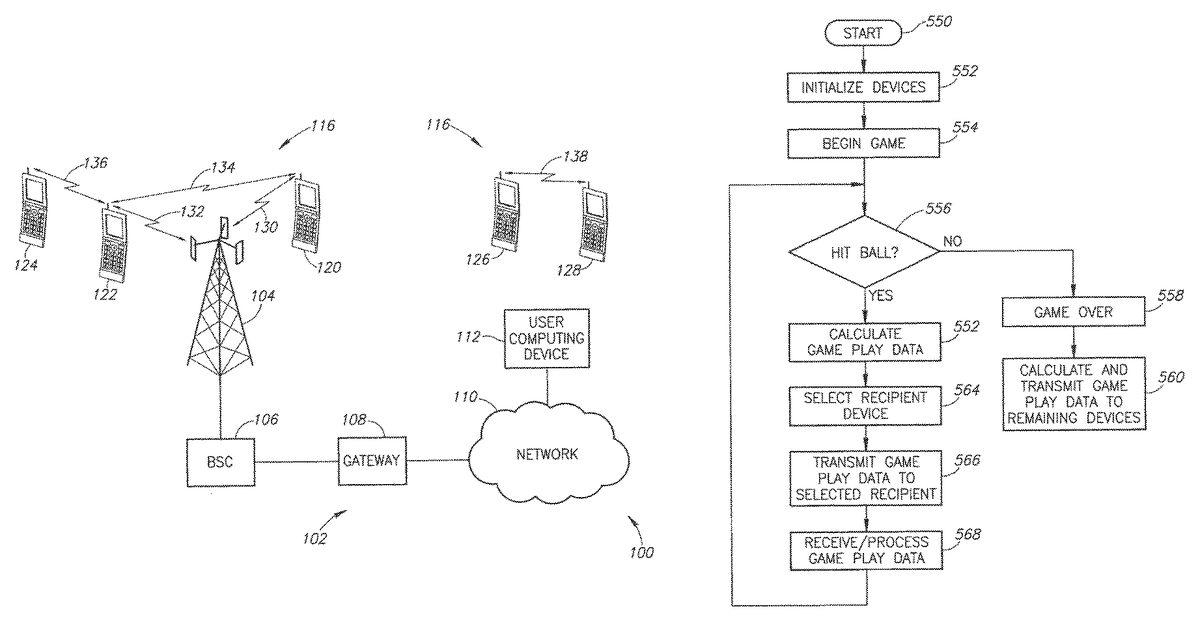
DETAILED DESCRIPTION OF THE INVENTION The system described herein extends the normal operational features of conventional wireless communication devices. As described above, the conventional wireless communication device communicates with a wireless communication network base station using a first transceiver (i.e., a network transceiver). The extended capabilities described herein provide a second transceiver device that allows wireless communication devices to communicate directly with each other over a short distance and further describes network management techniques capable of managing a dynamic network that may change quickly. The wireless communication devices are illustrated as part of a system100illustrated in the system architecture inFIG. 1. Portions of the system100are conventional wireless network components that will be described briefly herein. The non-network communication capability, which may be referred to herein as a “jump-enabled” device or a “jump” device, will be described in greater detail below. The term “jump” refers to the ability of a wireless device designed and operated in accordance with the present teachings to jump from one short-range wireless network to another. A conventional wireless communication network102, sometimes referred to as a public land mobile network (PLMN), includes a base station104. Those skilled in the art will appreciate that the typical wireless communication network102will include a large number of base stations104. However, for the sake of brevity and clarity in understanding the present invention,FIG. 1illustrates only a single base station104. The base station104is coupled to a base station controller (BSC)106. In turn, the BSC106is coupled to a gateway108. The BSC106may also be coupled to a mobile switching center (not shown) or other conventional wireless communication network element. The gateway108provides access to a network110. The network110may be a private core network of the wireless communication network102or may be a wide area public network, such as the Internet. InFIG. 1, a user computing device112is illustrated ...
DETAILED DESCRIPTION OF THE INVENTION
The system described herein extends the normal operational features of conventional wireless communication devices. As described above, the conventional wireless communication device communicates with a wireless communication network base station using a first transceiver (i.e., a network transceiver). The extended capabilities described herein provide a second transceiver device that allows wireless communication devices to communicate directly with each other over a short distance and further describes network management techniques capable of managing a dynamic network that may change quickly.
The wireless communication devices are illustrated as part of a system100illustrated in the system architecture inFIG. 1. Portions of the system100are conventional wireless network components that will be described briefly herein. The non-network communication capability, which may be referred to herein as a “jump-enabled” device or a “jump” device, will be described in greater detail below. The term “jump” refers to the ability of a wireless device designed and operated in accordance with the present teachings to jump from one short-range wireless network to another.
A conventional wireless communication network102, sometimes referred to as a public land mobile network (PLMN), includes a base station104. Those skilled in the art will appreciate that the typical wireless communication network102will include a large number of base stations104. However, for the sake of brevity and clarity in understanding the present invention,FIG. 1illustrates only a single base station104.
The base station104is coupled to a base station controller (BSC)106. In turn, the BSC106is coupled to a gateway108. The BSC106may also be coupled to a mobile switching center (not shown) or other conventional wireless communication network element. The gateway108provides access to a network110. The network110may be a private core network of the wireless communication network102or may be a wide area public network, such as the Internet. InFIG. 1, a user computing device112is illustrated as coupled to the network110.
For the sake of brevity, a number of conventional network components of the wireless communication network are omitted. The particular network components may vary depending on the implementation of the wireless communication network102(e.g., CDMA vs. GSM). However, these elements are known in the art and need not be described in greater detail herein.
Also illustrated inFIG. 1are wireless communication devices120-128. The wireless communication devices120-128are illustrative of many different types of conventional wireless communication devices capable of communicating with the base station104or other base stations (not shown) in the wireless communication network102. Those skilled in the art will appreciate that the wireless communication network102may communicate using a variety of different signaling protocols. For example, the system100may be successfully implemented using, by way of example, CDMA, WCDMA, GSM, UMTS, 3G, 4G, LTE, and the like. The system100is not limited by any specific communication protocol for the wireless communication network102.
As illustrated inFIG. 1, the wireless communication device120communicates with the base station104via a wireless network communication link130. Similarly, the wireless communication device122communicates with the base station104via a wireless network communication link132. Each of the wireless communication devices illustrated inFIG. 1(e.g., the wireless communication devices120-128) contain a conventional transmitter/receiver or transceiver components to permit conventional communication with the wireless communication network102via the base station104or other base station (not shown). Operational details of conventional network communication are known in the art and need not be described in greater detail herein.
In addition to the conventional network transceiver components, the jump-enabled wireless communication devices illustrated inFIG. 1(e.g., the wireless communication devices120-128) also include a second short-range transceiver to allow direct communication between the devices. This short-range communication is accomplished without reliance on the wireless communication network102. Indeed, as will be described in greater detail below, the short-range transceivers in the mobile communication devices120-128permit the dynamic formation of a short-range communication network116that does not rely on the wireless communication network102provided by any wireless service provider. Thus, wireless communication devices can rely on the conventional wireless communication network102for some communications, but may also be part of the short-range communication network116formed between the mobile devices themselves. In the example ofFIG. 1, the wireless communication device120communicates with the base station104via the wireless network communication link130. Similarly, the wireless communication device122communicates with the base station104via the network wireless communication link132. However, in addition, the wireless communication devices120and122may communicate directly with each other via a short-range communication link134.
As illustrated inFIG. 1, the wireless communication device124is not in communication with the wireless communication network102. However, the wireless communication device124can communicate directly with the wireless communication device122via a short-range wireless communication link136. Also illustrated inFIG. 1are the wireless communication devices126-128. Although neither of these devices is in communication with the wireless communication network102, the two devices are in direct communication with each other via a short-range wireless communication link138. Thus, jump-enabled wireless communication devices must be in proximity with each other, but need not be in communication with the wireless communication network102or even in an area of wireless coverage provided by the wireless communication network.
The dynamic formation of one or more short-range networks116allows communication between the wireless communications devices120-128independent of the wireless communication network102even if the wireless communication network102is present and operational. The short-range communication network116advantageously allows communication in settings where the wireless communication network102is not present or in a situation where the wireless communication network is unavailable. For example, the wireless communication network102may be unavailable during a power outage or an emergency situation, such as a fire, civil emergency, or the like. In contrast, the short-range communication network116does not rely on any infrastructure, such as cell towers, base stations, and the like. As will be described in greater detail below, the short-range communication network116may be extended as jump-enabled wireless communication devices move throughout a geographic location.
FIG. 2is a functional block diagram illustrative of one of the wireless communication devices illustrated inFIG. 1(e.g., the wireless communication device120). The wireless communication device120includes a central processing unit (CPU)150. Those skilled in the art will appreciate that the CPU150may be implemented as a conventional microprocessor, application specific integrated circuit (ASIC), digital signal processor (DSP), programmable gate array (PGA), or the like. The wireless communication device120is not limited by the specific form of the CPU150.
The wireless communication device120inFIG. 2also contains a memory152. In general, the memory152stores instructions and data to control operation of the CPU150. The memory152may include random access memory, ready-only memory, programmable memory, flash memory, and the like. The wireless communication device120is not limited by any specific form of hardware used to implement the memory152. The memory152may also be integrally formed in whole or in part with the CPU150.
The wireless communication device120ofFIG. 2also includes conventional components, such as a display154and a keypad or keyboard156. These are conventional components that operate in a known manner and need not be described in greater detail. Other conventional components found in wireless communication devices, such as a USB interface, Bluetooth interface, camera/video device, infrared device, and the like, may also be included in the wireless communication device120. For the sake of clarity, these conventional elements are not illustrated in the functional block diagram ofFIG. 2.
The wireless communication device120ofFIG. 2also includes a network transmitter162such as may be used by the wireless communication device120for the conventional wireless communication network with the base station104(seeFIG. 1).FIG. 2also illustrates a network receiver164that operates in conjunction with the network transmitter162to communicate with the base station104. In a typical embodiment, the network transmitter162and network receiver164share circuitry and are implemented as a network transceiver166. The network transceiver166is connected to an antenna168. The network transceiver166is illustrated as a generic transceiver. As previously noted, the mobile communication devices (e.g., the mobile communication devices120-128) may be implemented in accordance with any known wireless communication protocol including, but not limited to, COMA, WCDMA, GSM, UMTS, 3G, 4G, WiMAX, LTE, or the like. Operation of the network transceiver166and the antenna168for communication with the wireless communication network102is well-known in the art and need not be described in greater detail herein.
The wireless communication device120ofFIG. 2also includes a short-range transmitter172that is used by the wireless communication device120for direct communication with other jump-enabled wireless communication devices (e.g., the wireless communication device122ofFIG. 1).FIG. 2also illustrates a short-range receiver174that operates in conjunction with the short-range transmitter172to communicate directly with other jump-enabled wireless communication devices (e.g., the wireless communication device122ofFIG. 1). In a typical embodiment, the short-range transmitter172and short-range receiver174are implemented as a short-range transceiver176. The short-range transceiver176is connected to an antenna178. In an exemplary embodiment, the antennas168and178may have common components are implemented as a single antenna.
FIG. 2also illustrates a controller182and a data storage area184. As will be described in detail below, the controller182controls the exchange of data between wireless communication devices that become part of the short-range communication network116. The data storage184contains messaging data that will be exchanged between wireless communication devices in the short-range communication network116. The data storage area184may be implemented as any convenient data structure. As will be described in greater detail below, the data storage area contains data (e.g., messages, personal profile information of the user and user contacts, a geographical location tag for each contact, and the like) that will be exchanged between wireless communication devices. The data may be stored as a simple list, part of a database, or any other convenient data storage structure. The data storage area184also stores a list of other nearby wireless communication devices that form part of the short-range wireless communication network116.
The various components illustrated inFIG. 2are coupled together by a bus system186. The bus system may include an address bus, data bus, power bus, control bus, and the like. For the sake of convenience, the various busses inFIG. 2are illustrated as the bus system186.
In one embodiment, when the jump-enabled wireless communication device120comes within range of any other jump-enabled wireless communication device (e.g., the wireless communication device122ofFIG. 1), it establishes a short-range wireless communication link (e.g., the short-range wireless communication link134).
In an exemplary embodiment, the short-range transceiver176may be designed for operation in accordance with IEEE standard 802.11, sometimes referred to as WiFi. Many modern wireless communication devices are equipped with WiFi and may be readily upgraded to support the functionality described herein. Because the wireless communication devices120-128all include WiFi capability, short-range communication networks116may be formed even though the wireless communication devices may be designed to operate with incompatible wireless communication networks102. For example, the wireless communication device122may be configured for operation with a GSM implementation of the wireless communication network102. The wireless communication device124may be configured for operation with a CDMA implementation of a wireless communication network102. Even though the wireless communication devices122-124are incompatible with respect to the respective wireless communication networks102, the wireless communication devices122-124may still communicate directly with each other via the short-range communication network116. Thus, the wireless communication devices120-128may operate compatibly to form the short-range communication networks116even though the network transceivers166(seeFIG. 2) may operate with different incompatible wireless communication networks102.
Various techniques for establishing the short-range communication network116(seeFIG. 1) are described in U.S. application Ser. No. 12/397,225 filed on Mar. 3, 2009, now U.S. Pat. No. 7,970,351, U.S. application Ser. No. 12/616,958 filed on Nov. 12, 2009, U.S. application Ser. No. 12/958,296, filed on Dec. 1, 2010, and U.S. application Ser. No. 13/093,988 filed on Apr. 26, 2011, the entire disclosures and content of which are hereby incorporated by reference in their entirety.
The jump-enabled wireless communication device120also has numerous web-enabled applications. For example, an individual user may set up a JUMMMP webpage202with information regarding that individual. In this aspect, the jump webpage202may be similar to individual webpages or websites with any other conventional social network. The JUMMMP web page202may be accessed via the network110from the user computing device112(seeFIG. 1). Alternatively, the jump website may be accessed by any web-enabled wireless communication device. For example, inFIG. 1, a non-network wireless communication link134has been established between the wireless communication devices120and122. Some data can be exchanged directly between devices.
The data storage area184in each wireless device can be configured to contain profile data for that user as well as preference data. When two wireless devices make contact, they can exchange profile information to determine whether the users of the devices may be socially compatible or have sufficient common interests that they should meet. The profile data can include name, age, sex, height, weight, contact information (e.g., telephone number, email address, web link, etc.), background information (e.g., birthplace), education information (e.g., alma mater, degree(s), etc.), hobbies, sports, favorite sports teams, and the like. The user can add as much or as little as they desire. They can also determine different levels of information sharing. For example, the user can provide only basic information at the outset and more information if there is a match.
The preference data in the data storage area184may contain data indicating the type of person the user may wish to meet. For example, a male of a certain age range may wish to meet a female of a certain age range that has similar hobbies, educational background, or sports interests. When two wireless communication devices (e.g., the wireless communication devices120and122) establish a communication link (e.g., the non-network wireless communication link134), the devices exchange the profile data, which is analyzed by the controller182(seeFIG. 2) with respect to the user preference data. If a match occurs between the received profile data and the preference data stored in the profile storage184, a contact indicator is generated to advise the users that there is a nearby individual that they may want to meet.
Following an initial contact, the user of a wireless device (e.g., the wireless device120) may use the web-browsing capability of the wireless communication device to access an individual JUMMMP web page202(seeFIG. 3) for the individual with whom contact has just been made. This embodiment is illustrated inFIG. 1where the wireless communication device120communicates with the base station104via the network wireless communication link130. The wireless communication device120may use conventional web-browsing techniques to request access to a JUMMMP website200via the network110. Further, the wireless communication device120may request access to the individual JUMMMP webpage202of the new contact (e.g., the user of the wireless communication device122). In an exemplary embodiment, initial data exchange between the wireless communication devices120-122via the non-network wireless communication link134may include a link to the JUMMMP webpage202. That is, if a match is determined by the controllers182in the respective wireless communication devices120and122, the wireless communication device120may use the transmitted JUMMMP web page link to easily access the JUMMMP webpage202and get more information about the new contact. Thus, the initial social contact made via the non-network wireless communication link134can readily provide additional information, in the form of a web link to allow the users of the wireless communication devices to gain further information via the wireless communication network102.
In yet another aspect, the system100can utilize information from existing social networks. In a typical social network website206, each individual web page208has a list of “friends” or “contacts”210that are maintained for that individual. In one embodiment, a jump-enabled wireless communication device (e.g., the wireless communication device120) may download the contact list for storage as part of the profile storage184. This is also illustrated inFIG. 3where the individual JUMMMP web page202includes a contact list204that contains a list of all individuals that the owner of the individual web page202has identified as part of that individual's social network. In this aspect, the contact list204may be downloaded via the wireless communication network102to the wireless communication device120for storage in the profile storage184.
In operation, the wireless communication device120searches for contacts in the manner described above. When a non-network wireless communication link (e.g., the non-network wireless communication link134) is established, the profile data is exchanged between the wireless communication devices120and122, in the manner described above. If the user of the wireless communication device122is already on the contact list204(now downloaded and stored in the profile storage184), the wireless communication device120may immediately generate a contact notification to the user of the wireless communication device120. In this embodiment, the controller184need not do a detailed comparison between the profile data received from the wireless communication device122and the stored preference data stored in the profile storage184. Rather, the mere match between the user name of the wireless communication device122in the received profile data provides a match with the contact list204and the contact notification is generated. In another aspect of this embodiment, the wireless communication device120may transmit a web link to the individual web page202to enable the user of the wireless communication device122to gain additional information about the individual user of the wireless communication device120. This may be in place of, or in addition to, an individual jump web page link, described above. Thus, system100allows seamless integration with existing social network websites as well as the JUMMMP network website200.
The examples provided above extract data from the JUMMMP network website200or the social network website206and provide it to the wireless communication devices120and/or122. However, the reverse process may also be implemented by the system100. Following the determination that a match exists between the wireless communication devices120-122, data, such as the profile data may be automatically extracted from the wireless communication device (e.g., the wireless communication device120) and provided to the JUMMMP network website200and/or the social network website206for the user of the wireless communication device122. For example, the user profile data from the wireless communication device120may be added to the contact list204on the JUMMMP network web page202of the user of the wireless communication device122. Other profile information or other user-authorized information may also be used to populate the individual JUMMMP web page202and/or the individual web page208of the social network. Thus, data stored within the wireless communication device may be extracted and used to populate data bases or other data storage structures.
In the embodiment described above, when a match notification is generated, the profile data transmitted by one wireless communication device (e.g. the wireless communication device120inFIG. 1) may be automatically extracted and sent to the individual JUMMMP web page202(seeFIG. 3) for the user of the wireless communication device122. Furthermore, any additional information authorized by the user of the wireless communication device120may be extracted upon generation of a match notification and sent to the individual JUMMMP web page202for the user of the wireless communication device122. This may include information described above as optional profile data, such as an email address, telephone numbers, web page links, and the like. This automatic extraction process advantageously allows the user to automatically store information from contacts in the user's individual JUMMMP web page202. At a subsequent time, the user may access his own individual JUMMMP web page202to retrieve the stored information and to organize or further utilize the stored information. This may be particularly advantageous in a situation where the user of the wireless communication device120makes a number of contacts in a short period of time. While the wireless communication device120may store the profile data from multiple contacts, the automatic extraction and storage process described herein allows the data to automatically be extracted and forwarded to the users individual JUMMMP web page202for future use. Those skilled in the art will appreciate that the automatic data extraction and storage may also be performed on the individual web page208(seeFIG. 4) associated with the social network website206.
As previously described, information may also be extracted from the JUMMMP network website200or the social network website206and provided to the wireless communication devices once it has been determined that a match exists. Alternatively, further authorization may be required prior to the retrieval of data from the JUMMMP network website200or the social network website206. As also discussed above, data from the wireless communication devices120-122may be extracted and used to provide information to the JUMMMP network website200and/or the social network website206. Once a match has been established, data, such as user profile data, may be extracted from the wireless communication devices120-122and provided to the JUMMMP network website200and/or the social network website206. This data is automatically extracted from the wireless communication device (e.g., the wireless communication device122inFIG. 6) and stored in the individual JUMMMP web page202associated with the user of the wireless communication device120. Alternatively, further authorization beyond a match determination may also be required. The extracted data may transmitted to the individual JUMMMP web page202vie the PLMN102(seeFIG. 1) or via the access point140(seeFIG. 3). This automatic process advantageously allows the user to collect profile data from a number of contacts and automatically have the information extracted and used to populate a data storage area on the individual's web page. In one embodiment, the data may be extracted from known data fields. In this situation, the data may be used to automatically populate data storage locations or cells in a database, spreadsheet, data table, or any other convenient data structure. The precise form of the data structure is not critical to satisfactory implementation of the data extraction and storage process.
Thus, the system100may automatically extract data and populate a data structure in an individual's web page for future use. While the above process has been described with respect to the embodiment ofFIG. 3, those skilled in the art will appreciate its applicability to other system embodiments illustrated in other figures, including an embodiment where the extracted profile data is transmitted to the individual JUMMMP web page202(or the individual social network web page208) via the PLMN102, the access point140or via another wireless communication device that forms part of the short-range communication network116.
As will be discussed in greater detail below, the system100goes beyond some of the conventional operation of WiFi standards to permit a large number of wireless communication devices to communicate directly with each other. In one embodiment, a local hot spot is used to initiate the formation of the short-range communication network116. Once established, the short-range communication network116may continue to exist even if the hot spot (or group owner) is no longer present. In yet another alternative embodiment, described below, the wireless communication devices may be pre-programmed to utilize a common SSID, IPrange, and port to spontaneously form a short-range communication network116even in the absence of any hot spot.
In an exemplary embodiment of the system100, each wireless communication device (e.g., the wireless communication devices120-128) transmits a beacon signal with the same SSID, such as the SSID “JUMMMP” to identify the device as a jump-enabled wireless communication device. In addition, the beacon frame includes several other data fields such as a media access layer (MAC) address for source and destination. In the beacon frame, the destination MAC address is set to all ones to force other wireless communication devices to receive and process the beacon frame. The beacon frame used in the system100may also include conventional elements, such as a time stamp used for synchronization with other wireless devices, information on supported data rates, parameter sets that indicate, for example, transceiver operational parameters such as the IEEE 802.11 channel number and signaling method such as operation at the physical layer (PHY) and operation in a direct frequency spectrum (DSSS) or a frequency hopping spread spectrum (FHSS) operational modes. These conventional WiFi parameters are known in the art and need not be described in greater detail herein.
In addition, since there is no access point, all jump-enabled wireless communication devices take on the responsibilities of the MAC layer that controls, manages, and maintains the communication between the jump-enabled wireless communication devices by coordinating access to the shared radio channel and the protocols that operate over the wireless medium. In an exemplary embodiment, the MAC is implemented in accordance with IEEE 802.2. At the PHY layer, the transceiver may operate in a DSSS or a FHSS operational mode. Alternatively, the PHY layer may be implemented using infrared transceivers. The IEEE 802.11 standard defines a common operation whether devices are using the ad hoc or the infrastructure mode. The use of the ad hoc mode only affects protocols, so there is no impact on the PHY layer. Thus, the wireless communication device120may operate under IEEE 802.11a at 5 gigahertz (GHz) under IEEE 802.11b/g at 2.4 GHz, or IEEE 802.11n, which operates at both 2.4 GHz and 5 GHz. Those skilled in the art will appreciate that the wireless communication device of the system100may be readily adapted for operation with future versions of IEEE 802.11.
In an alternative embodiment, the wireless communication devices120-128may be configured in accordance with IEEE WiFi Direct standards. WiFi Direct allows any wireless communication device in the short-range communication network116to function as the group owner. WiFi Direct simplifies the process of establishing a communication link. For example, the WiFi protected set up allows a communication link to be established by entering a PIN or other identification or, simply pressing a button. As will be described herein, the jump-enabled wireless communication devices actively seek to establish links with other jump-enabled devices to automatically establish a short-range communication network116.
In yet another alternative embodiment, illustrated inFIG. 3, the jump-enabled wireless communication devices (e.g., the wireless communication devices120-122) may communicate with an access point140, such as a WiFi base station, WAP, wireless router, or the like. As will be described in greater detail below, a wireless communication device (e.g., one of the wireless communication devices120-124) may function as the access point140to permit others of the wireless communication devices in the short range communication network116to access the network110via the wireless communication device serving as the access point.FIG. 3illustrates a wireless communication link142established between the access point140and the wireless communication device120. Similarly, the wireless communication device122establishes a wireless communication link144with the access point140. Thus, a short-range communication network116ais formed in conjunction with the access point140.
To assist in a better understanding of the present disclosure, short-range communication networks will be generally referred to by the reference116. Specific examples of short-range communication networks will be referred to by the reference116and an alphabetic identifier (e.g., the short-range communication network116ainFIG. 3).
Depending on the physical proximity of the wireless communication devices120-124, there may be one or more short-range communication networks116formed. In the example ofFIG. 3, the wireless communication devices120-122are both within range of the access point140. Therefore, the first short-range communication network116acan be formed with the wireless communication devices120-122and the access point140.
The wireless communication device124is within range of the wireless communication device122, but is not within range of the access point140. In one embodiment, the wireless communication device124may be become part of the short-range communication network116avia the wireless communication device122. In this embodiment, the wireless communication device122functions as a “repeater” or relay to relay information between the wireless communication device124and other parts of the short-range communication network116a.In another embodiment, a second short-range communication network116bis formed with the wireless communication devices122-124. In this exemplary embodiment, the wireless communication device122is part of both short-range communication networks116a-116b.The wireless communication device122may simultaneously be a member of both short-range communication networks116a-116bor may be logically connected to both short-range communication networks116a-116bby alternately switching between the short-range communication networks116a-116b.
The access point140is coupled to the network110in a conventional manner. This can include a wired or wireless connection directly to the network110or via an intermediate network gateway, such as those provided by an Internet Service Provider (ISP).FIG. 3also illustrates a JUMMMP Network website200, which may support an individual web page202for each member (e.g., an individual person, business, organization, etc.) of the JUMMMP Network.FIG. 3also illustrates a generic conventional social network website206, which may support an individual web page208for each member of the social network. The JUMMMP network website200and social network website206are each coupled to the network110. Although illustrated inFIG. 3as two separate network websites, those skilled in the art will appreciate that the JUMMMP website200effectively functions as a social network website. Similarly, the JUMMMP website technology can be incorporated into existing social network websites. Thus, the two separate websites illustrated inFIG. 3can effectively be combined into a single website.
As discussed in detail in co-pending U.S. application Ser. No. 12/616,958, filed on Nov. 12, 2009 and assigned to the assignee of the present application, the user of a jump-enabled wireless communication device (e.g., the Wireless device120) may use the web-browsing capability of the wireless communication device to access the individual jump web page202for the individual with whom contact has just been made to learn more about that individual. Alternatively, the user of a jump-enabled wireless communication device (e.g., the wireless device120) may use the web-browsing capability of the wireless communication device to access the user's own individual jump web page202to store information for the individual with whom contact has just been made. A contact list204, which is typically a portion of the individual jump web page202is configured to store contact information. Similarly, the individual jump web page208of the social network206can include a contact list210to store contact information. In one embodiment, the contact information may include a user profile exchanged along with individual messages between users. As will be discussed in greater detail below, the user profile can include user name and preferences, as well as information about the specific exchange of messages. For example, the user profile can include the date and time at which messages were exchanged, geo-location data (e.g., latitude and longitude) of the sender of a message, and the like, and can also be stored as user profile data in the contact list204. Applications for the profile data are described in greater detail below.
The wireless communication devices120-128(seeFIG. 1) generally have sufficient memory capacity to temporarily store contact information. In an exemplary embodiment, the wireless communication device (e.g., the wireless communication device120) can temporarily store new contact information until access to the network110becomes available at a later time. In addition, the wireless communication device120can store designated contact information (e.g., “Favorites”) on a more permanent basis. Long-term storage of contact information requires access to the network110. In the embodiment ofFIG. 1, access to the network110may be provided via the base station104in a conventional manner. The wireless communication device122may access the network110by communicating directly with the base station104. In the embodiment ofFIG. 3, access to the network110may be provided via the access point140, as described above. For example, the wireless communication device122inFIG. 1may access the network110by communicating directly with the access point140via the short-range communication link144. Alternatively, the wireless communication device122can access the network110and the JUMMMP network website200via the wireless communication link132to the base station104. Network access via the gateway108is well known in the art and need not be described in greater detail herein.
In an alternative embodiment, access to the network110may be provided via another jump-enabled wireless communication device. For example, inFIG. 1, the wireless communication device122can communicate with the base station104via the wireless communication link132while the wireless communication device124cannot communicate directly with the base station. However, the wireless communication device124is in proximity with the wireless communication device122and can communicate with the wireless communication device122via the wireless communication link136as part of the short-range communication network116. In this embodiment, the wireless communication device124can use the wireless communication device122as a repeater or relay to allow the wireless communication device122to access the network110via the wireless communication device122and the base station104.
Similarly, in the embodiment ofFIG. 3, the wireless communication devices120-122can communicate directly with the access point140via the wireless communication links142-144, respectively. The wireless communication devices120-122can also communicate with each other via the access point140thus forming the short-range communication network116a.As seen inFIG. 3, the wireless communication device124cannot communicate directly with the access, point140. However, the wireless communication device124is in proximity with the wireless communication device122and can communicate with the network110via the wireless communication device122and the access point140.
As previously noted, the system100provides for the dynamic formation and rapid change in the topography of the short-range communication networks116. For example,FIG. 1illustrates a first short-range communication network116formed with the wireless communication devices120-124and a second short-range communication network116formed between the wireless communication devices126-128.FIG. 4illustrates the dynamic nature of the wireless communication networks116. For example, if the wireless communication device128is initially within range of the wireless communication device126, but out of range of the access point140, the wireless communication devices126-128may form a short-range communication network116cusing the short-range communication link138. If the wireless communication device126comes within range of the access point140, a wireless communication link212is formed. In that event, the wireless communication device126may become part of a short-range communication network116dformed between the access point140and the wireless communication devices120and126. At this particular moment in time, the mobile communication device126may be part of both the short-range communication network116cand the short-range communication network116d.As discussed above, the wireless communication device126may actually be part of both the short-range communication networks116c-116dor may logically be connected to both the short-range wireless communication networks by switching back and forth between the short-range communication networks116c-116d. The logical switching between the short-range communication networks116c-116dis transparent to the user. Other examples of the short-range communication network116are described below in which no access point140is present.
Alternatively, the wireless communication device128may become part of the short-range communication network116dusing the wireless communication device126as a relay to the access point140. If, at a later time, the wireless communication device128comes within range of the access point140, a wireless communication link214is formed therebetween. At that point in time, the short-range communication network116ceffectively ceases to exist since the wireless communication devices126-128are now part of the short-range communication network116d.
The wireless communication device120may be part of the short-range communication network116dby virtue of the short-range communication link142coupling the wireless communication device120to the access point140. If the wireless communication device120comes within range of the wireless communication devices122-124, wireless communication links216-218will be formed to couple the wireless communication devices120-124and thereby dynamically form a short-range communication network116e.At this point in time, the wireless communication device120may simultaneously be part of the short-range communication network116dand the short-range communication network116e.Alternatively, the wireless communication devices122-124may become part of the short-range communication network116dvia the wireless communication device120.
If the wireless communication device120subsequently moves out of range of the access point140, the wireless communication link142is broken. Therefore, there will no longer be an overlap between the short-range communication networks116d-116e. The wireless communication device120would remain part of the short-range communication network116eso long as it remains within range of the wireless communication device122, the wireless communication device124, or both. Thus, those skilled in the art will appreciate that short-range communication networks are dynamically formed, modified, and dissolved as the wireless communication devices move in and out of range with each other and central points, such as the access point140. Furthermore, if the wireless communication device120comes back into range of the access point140, the wireless communication link142can be reestablished. When this happens, all prior communications from the short-range communication network116ewill be transferred to the short-range communication networks116dand116c(and vice-versa) through the re-echoing function described above. That is, the various wireless communication devices will resynchronize the data in the date storage area184(seeFIG. 2). Those skilled in the art will also appreciate that the short-range communication networks116may be formed, modified, and dissolved without the presence of the access point140.
FIG. 4illustrates the wireless communication device120as a key component in the short-range communication network116ebecause it connects the wireless communication devices122-124to the access point140. If the wireless communication device120suddenly moved out of range of the access point and/or the wireless communication devices122-124that connection may be broken. Similarly, if the user of the wireless communication device120suddenly turned off the device, the link between the short-range communication network116eand the access point140would disappear. The wireless communication devices122-124still communicate with each other via the wireless communication link136and will still search for other wireless communication devices with which to connect. In addition, either of the wireless communication devices122-124will attempt to find the access point140or a hot spot from which either of the wireless communication devices may access the network110.
FIG. 4illustrates a sparse network with only five wireless communication devices. However, those skilled in the art can appreciate that there may be a very large number of wireless communication devices in proximity with each other. For example, ifFIG. 4is illustrative of a large shopping mall, there may be hundreds of wireless communication devices within the mall. Thus, the short-range communication networks116may be large and extensive. There may be a large number of wireless communication devices that are simultaneously present in two or more short-range communication networks116. In addition, many wireless communication devices would provide overlapping coverage with multiple short-range communication networks116. In this scenario, the entire mall and surrounding parking area could be effectively covered by a mesh network comprising dozens or hundreds of short-range communication networks116. Thus, in the situation illustrated inFIG. 4where the wireless communication device120is turned off or moved out of range of other wireless communication devices is less likely to cause the total isolation of the short-range communication network116e.If the wireless communication device120were suddenly removed, either by powering down or by the departure from the area, many other wireless communication devices (not shown) in the same proximity would be able to replace the connectivity between the short-range communication network116eand the access point140.
Whenever a wireless communication device (e.g., the wireless communication device124) comes within range of other wireless communication devices, a short-range wireless communication network (e.g., the short-range wireless communication network116e), the wireless communication devices exchange message data with each other to thereby synchronize message data in the data storage area184(seeFIG. 2). At the end of the synchronization process, the data storage area184of each wireless communication device will contain the same message data, although messages may not be in the same sequence. In the example described above, when the wireless communication device124comes within range of the wireless communication device120and/or the wireless communication device122, the wireless communication links136and218are formed. Because the wireless communication device124has just joined the short-range communication network116e,the data storage area184of the wireless communication device124will not be synchronized with the data storage area of other wireless communication devices in the short-range communication network116e.During the synchronization process, the wireless communication device124transmits message data in its data storage area184. The wireless communication devices120and122receive the message data. The controller182(seeFIG. 2) in each wireless communication device receives the message data and merges the messages with the message data already stored within the data storage area184of the wireless communication devices120and122, respectively. The controller182in each of the wireless communication devices may also eliminate duplicate messages. In this manner, each wireless communication device manages the message data within its data storage area184.
As part of the synchronization process, the wireless communication devices120and122may also transmit the message data within their respective data storage areas184. The wireless communication device124receives the messages from the wireless communication devices120and122and merges the newly received messages in the data storage area184of the wireless communication device124. As described above, the controller182(seeFIG. 2) of the wireless communication device124may eliminate duplicate messages within its data storage area184. Following this synchronization process, all wireless communication devices in the short-range communication network116ewill have identical messages.
In an exemplary embodiment, the messages may be categorized as Public Messages, Group Messages, Direct Messages, and Status Messages Public Messages may be transmitted to anyone within range of the wireless communication device (e.g., the wireless communication device120). This may include emergency messages, messages broadcast from a retailer, and the like. Group Messages are intended for a specific group or organization, such as a scout group or employees of a particular company or any formed group. Direct Messages are private messages intended for a specific individual. In addition, the wireless communication device120may transmit Status Messages, which can include, by way of example, a list of other wireless communication devices in the particular short-range communication network116, a list of recent wireless communication devices in the particular short-range communication network, a list of other short-range communication networks in which the wireless communication device was recently a member, or the like. The data message process described above can include one or more of these message categories. Other message categories may be created as necessary.
U.S. patent application Ser. No. 13/093,998, entitled “SYSTEM AND METHOD FOR MANAGEMENT OF A DYNAMIC NETWORK USING WIRELESS COMMUNICATION DEVICES,” filed ON Apr. 26, 2011, and incorporated by reference in its entirety, provides additional details of the message exchange process. As described therein, the Public and Group Messages may be contained in one file and all Direct Messages contained in a separate file. The messages have a main header and individual message headers. The main header may include, by way of example, the date/time of the last modification, message count, the date/time of the last synchronization and the user name of the wireless communication device with which the last synchronization was performed. This information may help maintain synchronization between wireless devices.
The message data may include, but is not limited to, text message data, audio data, video data, multimedia data, or the like. As those skilled in the art will appreciate, Public Messages may be received and processed by any wireless communication device. In contrast, Group Messages may only be processed by a member of the designated group, while a Direct Message may only be processed by the individual wireless communication device for whom the message is intended.
Synchronization may occur directly between the wireless communication devices or via the access point140illustrated inFIG. 4. For example, message synchronization can occur between the wireless communication device120and the wireless communication device126using the access point140. In addition, as will be described in greater detail below, wireless communication devices can carry message data as they move from one short-range communication network to another.
In another embodiment, a retail business may broadcast Public Messages to nearby wireless communication devices. In an exemplary embodiment, the retail facility can set up a wireless access point (e.g., the wireless access point140inFIG. 3) to establish a short-range communication network116. For example, a retail facility in a shopping mall can transmit advertisement messages to nearby wireless communication devices. In a typical embodiment, these would be Public Messages that are freely relayed from one wireless communication device to another and from one short-range wireless communication network116to another. Using this form of message distribution, an advertisement from a retail facility will soon be disseminated to all wireless users in the area. The advertisements may take the form of text messages or any other data message described above.
In another aspect, an individual user may register with a business. Whenever the user comes within range of the short-range communication network116associated with the retail business, message data may be exchanged thus enabling the business to identify a particular user that is nearby. In this embodiment, the retail business may send a private advertisement message to the particular user. The private advertisement may be customized for the user based on a number of factors, such as the user's profile (e.g., the sex, age, and interests of the user), prior shopping patterns, or the like. It can also be based on statistical and history data that the retail business has collected on the user in one or more short-range communication networks116in the region around the retail business. For example, if a particular user has registered with a restaurant and comes within range of the short-range communication network116of that restaurant at a subsequent time after registration, the restaurant can send a private advertisement message to entice that user into the restaurant by offering a discount on a meal previously purchased by that user. If the user is a sports enthusiast, a sports bar could send a message that a particular sporting event (e.g., the user's college football team) is ongoing and offer a discount on a meal. In this manner, highly customized advertisements may be sent to individual users.
In some situations, the user may not be within range of the short-range communication network116of the restaurant, but may still be nearby. Because the wireless communication devices in the various short-range communication networks116relay messages, any message from a particular user may be relayed to the retail business via one or more short-range communication networks116. Thus, a business at one end of a mall may detect the arrival of a particular user at the opposite end of the mall and still transmit a customized advertisement message to that user.
FIG. 5illustrates the distribution of message data throughout multiple short-range communication networks116. For the sake of simplicity, the wireless communication devices are illustrated inFIG. 5merely as dots with associated reference numbers. Furthermore, the area of coverage of wireless communication devices may be illustrated as a circle inFIG. 5. Those skilled in the art will appreciate that the circle is a two-dimensional representation of the area of coverage of a particular wireless communication device. Those skilled in the art will appreciate that the wireless communication device transmits in three-dimensions and that the arc of coverage may be altered by natural or manmade barriers (e.g., terrain, plants, trees, walls, buildings, and the like). The area of coverage may even alter as the wireless communication device moves from one room to another within a building.
FIG. 5illustrates a scenario in which wireless communication devices travel from one short-range communication network116to another and thereby distribute data stored in the data storage area184of the traveling wireless communication device. InFIG. 5, the wireless communication device126may generate a Direct Message for a wireless communication device364having an area of coverage366that does not overlap with the communication range350of the wireless communication device126. In the example illustrated inFIG. 5, the Direct Message is contained within the data storage area184of the wireless communication device126possibly along with other messages. The Direct Message may have been generated by the wireless communication device126or may have been received by the wireless communication device126from another wireless communication device (not shown). The wireless communication device126uses the wireless communication link356to exchange message data with the wireless communication device120. In the example illustrated inFIG. 5, the wireless communication device moves out of the communication range350and into the communication range358of the wireless communication device128. In the present example, there may be a period where the wireless communication device120is not within range of any short-range communication network116. However, as the wireless communication device120moves within the coverage range358, it establishes the wireless communication link360with the wireless communication device128and exchanges message data therewith in the manner described above. In turn, the wireless communication device128exchanges data, including the Direct Message carried by the wireless communication device120, with the wireless communication device122using the wireless communication link354.
AsFIG. 5illustrates, the wireless communication device122is within a communication range368of a wireless communication device370. The wireless communication device122exchanges data, including the data originally carried by the wireless communication device120, to the wireless communication device370using a wireless communication link372. In the example ofFIG. 5, the wireless communication device370moves out of range of the wireless communication device122and out of the communication range358. At some later point in time, the wireless communication device370moves within the communication range366of the wireless communication device364, which is the intended recipient of the Direct Message originally stored in the data storage area184of the wireless communication device126. At this point, the wireless communication device370establishes a communication link372with the wireless communication device364. The wireless communication device370exchanges data in the data storage area184(seeFIG. 2) with the wireless communication device364. As previously discussed, the wireless communication device370is carrying the data originated by the wireless communication device126. This is true even though the wireless communication device370may have been out of range of any wireless communication devices for some period of time. Following the data exchange between the wireless communication devices370and364, the wireless communication device364now includes the data originally stored in the data storage area184of the wireless communication device126. Thus, it can be appreciated that the dynamic and fluid nature of the short-range communication networks116allows data to be exchanged between wireless communication devices that are in range of each other and for data to be carried from one short-range communication network116to another.
The example illustrated inFIG. 5shows only a single wireless communication device120moving from the communication range350to the wireless communication device358, the single wireless communication device370moving from the area of coverage368to the area of coverage366. However, those skilled in the art will appreciate that this scenario can be repeated by dozens of wireless communication devices. Using the example of a shopping mall, data may be originally exchanged between dozens of wireless communication devices within a single short-range communication network116. As each of those dozens of wireless communication devices fan out, they temporarily become members of other wireless communication devices and disseminate the data stored in their respective data storage areas184to potentially dozens of other wireless communication devices within the new short-range communication network. This form of “viral” distribution can effectively provide a mesh network in areas where there is a large accumulation of wireless communication devices. Thus, the data from the wireless communication device126in the example ofFIG. 5may, in fact, be delivered to the wireless communication device364through a multitude of pathways.
FIG. 5illustrates the movement of mobile communication devices from one short-range communication network116to another. Those skilled in the art will appreciate that the distances between short-range communication networks116may be considerable. Messages could be relayed from one wireless communication device to another and from short-range communication device to another. When a wireless communication device is temporarily out of range of a short-range communication network116, that wireless device will carry the messages stored in the data storage area184(seeFIG. 2) until it comes in contact with another short-range communication network. At that point, the message data will be transferred to other wireless communication devices in that short-range communication network116and each of those wireless communication devices will carry the message further until it reaches its intended recipient. Thus, a message could be carried a few feet to its intended destination or a few hundred miles to its destination.
When a large number of conventional wireless communication devices are in physical proximity, such as a sporting event or even in rush-hour traffic, a conventional service provider network (e.g., the base station104inFIG. 1) is often overwhelmed because many wireless communication devices are attempting to connect to the same base station. Thus, too many conventional mobile communication devices in proximity can be a debilitating situation. In contrast, the system100can actually take advantage of the presence of a large number of wireless communication devices because a large number of devices will facilitate the movement of messages independent of the conventional service provider network. Thus, the system100can facilitate rather than debilitate communication in the presence of a large number of mobile communication devices. For example, a message generated by one user in rush-hour traffic will be quickly relayed to many other wireless communication devices in the same rush-hour traffic. Thus, messages may move quickly up and down a roadway. In addition, some of the wireless communication devices will become part of short-range communication networks in other locations near the roadway. Thus, the message spreads up and down the roadway using the wireless communication devices in automobiles on the roadway and moves away from the roadway as automobiles enter and leave short-range communication networks adjacent to or near the roadway. The system100could move a message from, by way of example, Orange County to Los Angeles using a variety of short-range communication networks in the manner described above.
As previously discussed, messages may be categorized in several categories, such as Public Messages, Group Messages, Direct Messages, and Status Messages. In addition, a priority category may be created to disseminate emergency messages. The example ofFIG. 5illustrates one embodiment in which an emergency message may be generated by the wireless communication device126or received by the wireless communication device126from another wireless communication device (not shown). The emergency message can be disseminated to the recipient (e.g., the wireless communication device364inFIG. 10) in the manner described above. One distinction between an emergency message and other message types is that an emergency message will not be deleted from the data storage area of any wireless communication device until “Message Received” confirmation message is received or until some instruction is received to delete the emergency message from the data storage area184. In this embodiment, the emergency message may be distributed in the same fashion described above. When the emergency message reaches its intended recipient (e.g., the wireless communication device364), the recipient wireless communication device generates a “Message Received” or message receipt and transmits it back to the originator (e.g., the wireless communication device26or wireless communication device not shown). Because of the dynamic nature of the short-range communication networks116, the Message Received will likely be distributed via a different pathway with a different set of wireless communication devices in different sets of short-range communication networks116. As the Message Received is distributed, each wireless communication device uses the Message Received to delete the emergency message from the data storage area184. If a particular wireless communication device never received the emergency message, the Message Received may be ignored. Alternatively, the Message Received message can be delivered via the access point140or the network110(seeFIG. 1). For example, the wireless communication device364may receive the emergency message and generate the Message Received message for transmission via one or more short-range communication networks116. Additionally, the wireless communication device364may send the Message Received message via the network110. The Message Received message may be delivered to the network110via the access point140(seeFIG. 3) or via another wireless communication device having network access or via a base station (e.g., the base station104ofFIG. 1) and a gateway (e.g., the gateway108inFIG. 1). The Message Received receipt can be delivered to the originator of the emergency message or delivered to the individual web page208or individual JUMMMP web page202(seeFIG. 3) to notify the message originator that the message has been received.
A different emergency message scenario is also illustrated inFIG. 5. In this scenario, the system100may use the network110(seeFIG. 1) to further disseminate an emergency message. InFIG. 5, the wireless communication device120, which has already migrated from the communication area350to the communication area358now migrates again and comes within range of the access point140. As described above, the wireless communication link142is established between the wireless communication device120and the access point140. In one embodiment, the access point140may be part of one or more short-range communication networks116and further disseminate the emergency message in a conventional manner. Alternatively, the access point140may be a gateway to the network110to permit dissemination of the emergency message via the network110. In this embodiment, the emergency message may require additional headers to identify the recipient. Thus, the wireless access point140and network110may be used to disseminate the emergency message.
FIG. 6illustrates other scenarios in which wireless communication devices detect hot spots or become hot spots to facilitate the formation of short-range wireless communication networks116. InFIG. 6, there are two distinct short-range wireless communication networks116, designated as Group A, and Group B. Group A has a Group Owner A, which serves as the hot spot and, in the example ofFIG. 14, includes phones A1-A4. The wireless communication devices A1-A4are considered peers and may communicate with each other, if in range, or communicate via the Group Owner A. Similarly, Group B includes Group Owner B and wireless communication devices B1-B4. The wireless communication devices B1-B4are operating as peer devices and may communicate directly with each other, if in range, or communicate via the Group Owner B.
FIG. 6illustrates the group owners (i.e., Group Owner A and Group Owner B) at the center of each respective short-range communication network116to illustrate the potential range of a network. However, once the peer wireless communication devices become part of a short-range communication network116, they can freely communicate directly with other peer wireless communication devices of that network or any other short-range communication network with which they come into range. For example, the peer wireless communication devices A1and A4may communicate directly with each other if they move into communication range of each other.
InFIG. 6, a new wireless communication device, designated as R1, is out of range of Group Owner A and Group Owner B, but comes within range of the peer wireless communication device A2and the peer wireless communication device B2. In accordance with the system design, the wireless communication device R1searches for hot spots. The wireless communication device R1cannot communicate with either the network A or network B because it is out of range (indicated by the designation O.R.) of the hot spot (i.e., Group Owner A and Group Owner B) and therefore will not detect the transmitted SSID from the group owners. Because the wireless communication devices A2and B2are not hot spots, the wireless communication device R1will be unsuccessful in locating a short-range communication network116. In this situation, the wireless communication device R1will become a hot spot. While the wireless communication devices A2and B2are peers within their respective networks, they may still periodically scan for other hot spots. When the peer wireless communication devices A2and B2search for other hot spots, they will detect the newly created hot spot of wireless communication device R1. As soon as the wireless communication devices A2and B2detect the new hot spot provided by the wireless communication device R1, the wireless communication devices R1, A2, and B2will synchronize, as described above. The presence of the new hot spot provided by the wireless communication device R1effectively links together both network A and network B using the wireless communication devices A2and B2, respectively, as bridges. Thus, all of the phones in Network A and Network B are bridged together to form a larger short-range wireless communication network. The wireless communication devices in Network A and Network B, as well as the wireless communication device R1, will all be synchronized and have exchanged messages, as described above.
In the scenario ofFIG. 6, network A and network B are connected together via the wireless communication device R1with the wireless communication device R1effectively acting as a relay between the wireless communication devices A2and82. However, as the wireless communication devices in the network A and the network B move around, they may come into range of each other and can therefore communicate directly with each other. For example, the peer wireless communication devices A1and B1inFIG. 6may move within range of each other thus allowing direct communication between these devices.
Furthermore, those skilled in the art will appreciate that if the wireless communication device R1came within range of only one of the peer wireless communication devices A2and82, the wireless communication device R1would become a hot spot and be detected by the peer device of only one of the networks. For example, if the wireless communication device R1became a hot spot and came within range of the wireless communication device B2, the wireless communication device B2would act as a bridge or relay between the wireless communication device R1and the wireless communication devices of Network B.
FIG. 7illustrates a logical extension of the principles discussed with respect toFIG. 6. In the example ofFIG. 7, each of the peer devices (A1-A4of Network A and B1-B4of Network B) searches for and connects with other hot spots (i.e., the hot spots provided by wireless communication devices C1-K1). The wireless communication devices C1-K1may be the group owners of their respective smaller short-range wireless communication networks116or may be peer devices in other short-range wireless communication networks that periodically become hot spots to search for other wireless communication devices. Although not illustrated inFIG. 7, those skilled in the art will appreciate that the hot spot wireless communication devices C1-K1may have other peer devices (not shown) connected to that hot spot thus greatly expanding the overall reach of the short-range communication network116.
As discussed above, the wireless hot spot/group owner assigns the same MAC address to those wireless communication devices that detect the SSID beacon (e.g., SSID JUMMMP). In yet another alternative embodiment, the requirement of a group owner to initiate formation of a short-range communication network116can be eliminated. A program designed in accordance with the present teachings can be executed and utilize a predetermined channel SSID, IPrange, port, and MAC address associated with the JUMMMP functionality. A wireless communication device can simply broadcast a greeting message; if it is detected by another nearby wireless communication device, the other device can transmit its own messages thereby synchronizing the data storage area184(seeFIG. 3) of each device. In this manner a completely de-centralized short-range communication network can be formed. The wireless communication devices detect the presence of other nearby devices by virtue of the fact that they respond to the transmission of the greeting message.
Thus, it can be appreciated that the wireless communication system described herein provides a highly dynamic network in which a large number of wireless communication devices may be coupled together in a dynamic fashion to create a large number of short-range communication networks116and to permit individual users to come and go from any particular short-range communication network.
The short-range communication networks116may also advantageously be used for game play by the wireless communication devices. A number of single player games are known in the art. However, the short-range communication networks116enable multi-player games that do not require communication between the wireless communication devices using the PLMN102(seeFIG. 1). Traditional, multi-player games use a server to exchange data between game playing devices. In contrast, the multi-player games described herein do not require a server or even a network connection to the PLMN102. The data can be exchanged between the wireless communication devices by direct peer-to-peer communication, such as between the wireless communication devices122and124inFIG. 3. Alternatively, the communication between the wireless communication devices engaged in game play activity may be via an intermediary communication device. For example, the access point140(seeFIG. 3) may act as an intermediary device between the wireless communication devices120and122. That is, game play data transmitted by the wireless communication device120may be relayed to the wireless communication device122by the access point140. Similarly, the wireless access point140relays game play data from the wireless communication device122to the wireless communication device120. Alternatively, a different wireless communication device may act as the intermediary device. For example, the wireless communication device122shown inFIG. 4may act as an intermediary device between the wireless communication devices120and124. In one embodiment, the wireless communication device122may be a participant in a multi-player game along with the wireless communication devices122and124. Alternatively, the wireless communication device122may not be engaged in the game play activities, but merely serves as a relay of game play data between the wireless communication devices120and124. In yet another alternative embodiment, both peer-to-peer and intermediary devices can be used. For example, the wireless communication devices120-124inFIG. 3may all be participants in a game. The wireless communication devices122and124exchange game play data directly with each other via the communication link136. The wireless communication device120participates in the game play with the wireless communication devices122-124by exchanging game play data via the access point140.
When the wireless communication device, such as the wireless communication device120inFIG. 4transmits a data packet to the access point140, the access point will echo back the packet to the wireless communication device. When the wireless communication device120receives the echo packet, it serves as a confirmation that the packet was received by the access point140. If the wireless communication device receives a different packet, such as a packet of game play data, the wireless communication device processes the packet, but also assumes that the transmitted packet was not received by the access point140. In this event, the wireless communication device120will re-broadcast the data packet and await an echo to confirm that the data packet was received by the access point. The IP address of the wireless communication device is included in the broadcast packet; this permits the wireless communication device to verify the echo transmission.
The game play data is generated in accordance with game play rules that are specific to the game or may be generally applicable to broad classes of games. For example, the game play data generated by a multi-player game, such as Tic-Tac-Toe, may be different from the form of game play data generated by a chess game.
Various message types, such as Public Messages, Group Messages, and Direct Messages, have been described in detail above. The selection of a particular message type may depend on the particular game and/or user preferences. For example, a chess game may allow the exchange of game play data as a Public Message. This allows nonparticipants to view the progress of the game. In one embodiment, public viewers may also be able to comment on the game using a text window500(seeFIG. 8). Alternatively, the players may elect to play a private game. In this event, game play data may be exchanged as Direct Messages that can only be read by the individual participants in the text window500.
FIG. 8illustrates one example of game play using the short-range communication networks116.FIG. 8illustrates an example embodiment of data shown on the display154(seeFIG. 2) of the participating wireless devices, such as the wireless communication devices120and122. The game shown on the display154is Tic-Tac-Toe and may include text messages500between the game participants as well as other wireless communication devices that are also in the nearby network (i.e., the short-range communication network116) if the game and text messages are Public Messages. The display154also shows advertisements502, and status information504for the wireless communication devices120and122. In the game illustrated inFIG. 8, the display154shows a game play surface506. In the case of Tic-Tac-Toe, the game play surface506is a cross-hatch pattern well known for use in Tic-Tac-Toe. The display may also include optional game control buttons508. In certain game play embodiments, the entire game play surface506is visible to all players and is shown on the display154of each of the wireless communication devices120and122participating in the game play or observing the game play if the game is available to the public. In other game play embodiments, which will be described in greater detail below, only a portion of the game play surface506may be available for viewing on the display154.
Returning toFIG. 8, the entire game play surface506is visible on the display154for each wireless communication device (e.g., the wireless communication devices120and122). In one embodiment, the display154may include a cursor that is manipulated by a user of the wireless communication device using a cursor-controlled button (not shown), such as a track ball, set of directional buttons, or the like. The keyboard (not shown) on the wireless communication device may also be used in game play. However, it is common in wireless communication devices that the display154is a touch-sensitive display. In this embodiment, the user merely touches the display154in the desired location to activate a function associated with that display area.
In the example of the Tic-Tac-Toe game ofFIG. 8, the user of the wireless communication device (e.g., the wireless communication device120inFIG. 3) may activate game play by activating the “I'll Start” game control button508. In Tic-Tac-Toe, it is customary for the person starting the game play to use an “X” to indicate their selection while the opposing player uses an “O” to indicate their selection. Those skilled in the art will appreciate that other indicators, such as coloring the blocks of the game play surface506in different colors (e.g., Red and Black) to signify their selections. Other indicators may also be readily used. The game pieces for the first user, no matter what form they may take, may be generically described inFIG. 8as a first set of game play objects512while the opposing player may use different game pieces, referred to as a second set of game play objects514.
In the example ofFIG. 8, the first player selects the center position by pressing the touch-sensitive display154in the desired location. The software program executing the game on the wireless communication device120will display the first set of game play objects512(e.g., an “X”) on the display154of the wireless communication device120. The software program executing the game on the wireless communication device120also calculates the game play data, in the form of position data for the first set of game play objects512on the display154, and transmits the game play data from the first wireless communication device120to the second wireless communication device (e.g., the wireless communication device122) using the short-range transceiver176(seeFIG. 2) and, in this example, the access point140. As noted above, use of the short-range transceiver176avoids any need for communication of game play data using the PLMN.
The software program executing the game on the wireless communication device122will display the first set of game play objects512(i.e., the “X”) on the display154based on the game play data received from the wireless communication device120. Game play continues when the second player (e.g. the wireless communication device122) selects a position on the game play surface506to place the second set of game play objects514(e.g., an “O”). In response to the user input, the software program executing the game on the wireless communication device122also displays the second set of game play objects514based on the user input on the touch-sensitive display154. The software program executing the game on the wireless communication device122also calculates game play data, in the form of position data for the second set of game play objects514on the display154, and transmits the game play data from the second wireless communication device122to the first wireless communication device120using the short-range transceiver176. Again, it should be noted that there is no need for any communication using the PLMN to exchange game play data.
The process is repeated wherein the software program executing the game on the wireless communication device120will display the first set of game play objects512based on user selections on the touch-sensitive display154of the wireless communication device120and will display the second set of game play objects514on the display154based on the game play data received from the wireless communication device122. A similar process occurs with the software program executing on the wireless communication device122. However, the software program executing on the wireless communication device122will display the first set of game play objects512based on the game play data received from the wireless communication device120rather than user selection on the touch-sensitive display. It is the second set of game play objects514that is displayed based on user selections on the touch-sensitive display of the wireless communication device122. The game proceeds in the normal manner until one player has won or until there is a tie. Selection of a “New Game” game control button508will restart the process.
In addition to the game play data described above, the two wireless communication devices120and122can exchange text messages or other messages (e.g., audio or video messaging). The availability of social networking provides additional appeal to game play using the short-range wireless communication networks116. As previously noted, the exchange of text or other messages between the players may be in the form of Public Messages and therefore be available for view by anyone within range of the short-range communication network116that includes the game play participants (e.g., the wireless communication devices120and122). Alternatively, the messages may be Group Messages or Direct Messages as previously described.
The display154inFIG. 8also includes advertisements502. In an exemplary embodiment, the advertisements502can be provided to the wireless communication device (e.g., the wireless communication device120) using third-party or proprietary ad delivery technology. In one embodiment, a line of code is added to the software application executing the game on the wireless communication device120. The line of code describes the location of an advertisement and a link to a third-party ad provider, such as AdMob by Google. The ads come from a'Google AdMob server (not shown) to a delivery device, such as the access point140, for delivery to the wireless communication device120. There are a number of possibilities for the advertisements502. In one embodiment, the ads can be from Google AdMob, or other ad service provider, and are under the control of AdMob or other service provider. Revenue is provided through clicks on the advertisements502.
In another embodiment, the ads can be controlled by the owner of the software game program and under its control. The ads can be provided to AdMob and delivered to the wireless communication device in the manner described above. For this type of operation, there is generally no revenue provided by click-throughs, but it does provide promotions for the company or product being advertised.
In yet another embodiment, the advertisements502can be ads for a third party where the software application provider has negotiated a deal with the third party for revenue based on the number of impressions, the number of clicks, and the like. These advertisements can be provided to Google AdMob or other ad provider and an impression strategy may also be provided.
FIG. 9illustrates an example of the display154for the game of Checkers. Checkers is a two-player game and, in an exemplary embodiment, each of the wireless communication devices (e.g., the wireless communication devices120and122inFIG. 3) show the entire game play surface506in the form of a checkerboard. When the game is initialized, the display154of each of the wireless communication devices120and122will show the entire game play surface506as well as the first set of game play objects512and the second set of game play objects514. Although illustrated inFIG. 9as black and white checkers, those skilled in the art will appreciate that other colors, shapes, and the like may be used to represent the first and second sets of game play objects512and514. As discussed with respect to the Tic-Tac-Toe game ofFIG. 8, the display154inFIG. 9illustrates an area for text messages500and for advertisements502.
Following the initialization of the checkers game inFIG. 9, one player will move first. For example, the operator of the wireless communication device120manipulates the touch-sensitive display154to position the first set of game play objects512. The software program executing the checkers game on the wireless communication device120will display the first and second sets of game play objects512and514. When the player moves the first piece, one of the first set of game play objects512will be in a new position. The software program executing the game play on the wireless communication device120will display the first set of game play objects512with one of the pieces in a new position. The software program executing the game on the wireless communication device120also calculates the game play data, in the form of position data for the first set of game play objects512on the display154, and transmits the game play data from the first wireless communication device120to the second wireless communication device122using the short-range transceiver176(seeFIG. 2) and, in this example, the access point140. Again, the game play data is transmitted between the wireless communication devices120and122using the short-range transceivers176as part of the short-range communication networks116and does not require any communication via the PLMN.
The wireless communication device122receives the game play data. The software program executing the checkers game on the wireless communication device122will display the first set of game play objects512on the display154with one of the first set of game play objects in its new position. In turn, the user of the wireless communication device122selects one of the second set of game play objects514for movement. The software program executing the game on the wireless communication device122moves the selected one of the second set of game play objects514based on user operation and transmits the game play data to the wireless communication device120. The software program executing the game on the wireless communication device120receives the game play data and displays the second set of game play objects514based on the received game play data.
Thus, the software program executing the game on the respective wireless communication devices moves the game play objects for that user in response to user input and displays the other set of game play objects in response to received game play data. That is, the software program executing the game on the wireless communication device120moves the first set of game play objects512in response to user operation of that wireless device. The game play data resulting from movement of the first set of game play objects512is transmitted to the wireless communication device122. The software program executing the game on the wireless communication device120also displays the movement of the second set of game play objects514. However, the second set of game play objects514are moved on the display154of the wireless communication device120, not in response to user operation of the touch-sensitive display154, but as a result of game play data received from the wireless communication device122.
Similarly, the software program executing the game on the wireless communication device122moves the second set of objects514in response to user operation of the device and moves the first set of game play objects512in response to game play data received from the wireless communication device120.
Those skilled in the art will appreciate that a number of similar games are playable on the wireless communication devices utilizing the short-range communication networks116. For example, a chess game can be played using the same game play surface506as required for the checkers game inFIG. 9. However, those skilled in the art will appreciate that the chess game will require a different first set of game play objects512and a different second set of game play objects514. In addition, movement of the first and second sets of game play objects512and514are controlled by game rules for the game of chess rather than the game rules for the game of checkers. Other games, such as backgammon, scrabble, and other word games, and the like are also readily implemented using the short-range communication networks116described herein. All of the game play data for these various games is communicated between the game participants using the short-range communication networks116for direct peer-to-peer communication or communication via, by way of example, the access point140.
In each of the games described above, each player can see the entire game play surface506on the display154of the respective wireless communication device. Other games may be implemented by the wireless communication devices in which only a portion of the game play surface506is visible on each of the wireless communication devices. In Pong, an early video game, two players played an elementary game of ping pong on a single video screen. The players could control the vertical positioning of a “paddle” to intercept the ball.
In a new multi-player version, jPONG allows each player to only see a portion of the entire game play surface. If the player's paddle on one wireless communication device strikes the ball, the ball disappears off the display of that player and appears on the display of some other participant in the jPONG game play. Thus, each player only sees their portion of the game play surface.FIG. 10illustrates an example embodiment of jPONG using four wireless communication devices122-126illustrated, by way of example, inFIG. 4.
For the sake of convenience, the participants in the game play illustrated inFIG. 10are all shown as conventional wireless communication devices, such as a smart phone. However, those skilled in the art will appreciate that any network device having the short-range transceiver described above with respect toFIG. 2, can be configured for satisfactory operation as described herein. For example, the game play participants could be smart phones, PDAs, net computers, portable computing devices, iPads, and the like. The present disclosure is not limited solely to embodiments with smart phones.
In this example embodiment, the wireless communication devices120-124are all within range of each other and form direct peer-to-peer communication links to form the short-range wireless communication network116ein the manner described above. In contrast, the wireless communication device126participates in the jPONG game play by transmitting and receiving game play data via the access point140. Thus, game play may be conducted via one or more peer-to-peer connections using wireless communication devices and/or via one or more wireless access points (e.g., the access point140).
As noted above, the display154of each respective wireless communication device120-126shows only a portion of the total game play surface506(seeFIG. 8). That is, each player only sees the activity occurring on his portion of the overall game play surface506. In the example of jPONG where there are four participating players, there will be one ball for each player for a total of four balls. The balls may be generically referred to as game play objects where game play objects512-518are the balls of the wireless communication devices120-126, respectively.FIG. 10also includes an arrow to illustrate a direction of movement520for each of the balls512-518. Those skilled in the art will appreciate that the direction of movement arrows520do not appear in the actual game, but are merely used in the present description to illustrate the direction of movement of the balls512-518.
Thus, instead of a single ball shared between players, the jPONG game illustrated inFIG. 10includes one ball for each player. AlthoughFIG. 10illustrates an example with four players, jPONG may be satisfactorily played with as few as two players or more than four players. When the jPONG game play is initialized, the display154of each of the wireless communication devices120-126will display the respective balls512-518. Initially, the balls512-518move generally in a direction towards a first end154aof the display154. Using the touch-sensitive display154, the user can move a paddle522back and forth to intercept the ball before it reaches the first end154aof the display154. If the user positions the paddle522to intercept the respective balls512-518, the balls begin to move generally towards a second end154bof the display154.
As the balls512-518move off the respective displays154at the second end154b,the software program executing the game on each wireless communication device will calculate game play data to be transmitted to others of the wireless communication devices participating in the game. For example, the paddle522on the wireless communication device120can intercept the ball512and cause the ball to move in a direction towards the second end154bof the display154. When the ball512reaches the second end154bof the display154, the software program executing the jPONG game on the wireless communication device120calculates game play data associated with the ball512. In the example of jPONG, the game play data may be in the form of position and velocity data (e.g., speed and direction) of the ball512as it moves off the second end154bof the display154.
In an exemplary embodiment of jPONG, the software program executing the game play on the wireless communication device120will not allow the ball512to return immediately to the wireless communication device120. Rather, the software program executing the TONG game on the wireless communication device120will select one of the other wireless communication devices (e.g., the wireless communication devices122-126) to receive the ball512. In one embodiment, the recipient of the game play data for the ball512is randomly selected. Thus, with N players, there are N balls in play. After the initial play, any of the wireless communication devices may receive game play data for up to N−1 balls. As can be appreciated, if one wireless communication device receives more than one ball, some other wireless communication device will not receive in play data for any balls. This is illustrated inFIG. 11where the wireless communication device120receives game play data from the wireless communication devices122and124. In response to the received game play data, the software program executing the jPONG game on the wireless communication device120will display the balls514and516moving toward the first end154aof the display154. The user of the wireless communication device120must move the paddle522to intercept both of the balls514and516on its display154.
In contrast, the wireless communication device122receives no game play data and, for this round of play, has no balls to display. In turn, the wireless communication devices124and126have each received game play data for a single ball. The wireless communication device124received the game play data from the wireless communication device126while the wireless communication device126received game play data from the wireless communication device120. As can be appreciated by the inclusion of the direction of movement arrows520the balls may be deflected off of the lateral sides of display154between the first and second ends154a-154b.
The velocity of the balls and the angles with which they may bounce off the sides of the display154may be determined by a number of factors. In one embodiment, the velocity of the ball may increase each time it touches a paddle522. The ball velocity starts slow and increases to add to the excitement of the game. In an exemplary embodiment, the velocity of the ball is maintained as it moves from one wireless communication device to another. For example,FIG. 9illustrates the ball512moving toward the paddle522on the display154of the wireless communication device120. If the ball512is successfully struck by the paddle522, it will change direction and move toward the second end154bof the display154. The velocity at which the ball512leaves the second end of the display154bon the wireless communication device120is maintained when it appears on another of the wireless communication devices participating in the game play. That is, the direction and speed of the ball512appear on the display154of the wireless communication device126just as if the second ends154bof the two wireless communication device120and126were butted together.
In yet another exemplary embodiment, the paddle522may impart a “spin” to the ball to alter the direction of travel. In essence, the paddle522may put a “spin” on the ball based on factors such as the location on which the paddle and the ball intersect, movement of the paddle at the time of intersection, and the like. Those skilled in the art will appreciate that a number of variations of these parameters can be used to provide excitement in the game play.
This process continues where the users of each of the wireless communication devices120-126must move their respective paddles522to intercept all of the balls on its respective display154. If the player misses the ball and it encounters the first end154a,that player is eliminated from the game. The eliminated wireless communication device will send game play data to the other remaining wireless communication devices to indicate that it has been eliminated from the game. In this manner, no future balls will be directed to the eliminated wireless communication device. However, the ball originally associated with that wireless communication device will continue in play until there is a final winner. Thus, at some point in the game, there will be two wireless communication devices and four balls512-518. The game ends when only one player remains.
FIG. 12is a flow chart illustrating the overall operation of the jPONG game. At a start550, a number of wireless communication devices are within range of each other and decide to play the game. The software program is initialized on each device in step552. In the initialization process, the players may, by way of example, select a color for their ball and paddle522. Although not necessary for satisfactory operation of the game, it adds enjoyment to be able to identify the balls from the individual players. In the initialization process, the display154on each of the wireless communication devices (e.g., the wireless communication devices120-126) show the available color selections. As one player selects a particular color, that wireless communication device transmits game play data to the others of the wireless communication devices participating in the game play to indicate that color has been selected. In response to the color selection by one device, the remaining wireless communication devices will eliminate that color option from the display154. When each player has selected a color, the game can begin automatically at step554or a start game control button, such as the game control buttons508inFIG. 8, can be selected to begin the game in step554. As previously noted, each of the balls initially moves toward the first end154aof the display.
In decision556, the software program executing the jPONG game on each wireless communication device will determine whether the paddle522has intercepted the ball. If the paddle522has not intercepted the ball, the result of decision556is NO and, in step558, the game is over for that player. As previously discussed, the ball continues in play. In step560, the wireless communication device whose game play has ended performs a final calculation of game play data and transmits the game play data to the others of the wireless communication devices still participating in the game. The game play data includes the position and velocity data for the ball that has just been missed as well as an indication that the particular wireless communication device is no longer active in the game. The others of the wireless communication devices will therefore eliminate that wireless communication device as a possible destination for the game play data.
If the paddle522did strike the ball, the result of decision556is YES and the ball will begin to move toward the second end154bof the display154. When the ball reaches the second end154b,that particular wireless communication device calculates game play data in step562. In step564, the wireless communication device selects a recipient device from the remaining wireless communication devices still playing the game. In step566, the wireless communication device transmits the game play data to the selected recipient.
In step568, at least some of the participating wireless communication devices will receive game play data. As previously noted, it is possible that a given wireless communication device may not receive any of the balls512-518or a given wireless communication device may receive game play data for all four balls512-518. As previously discussed, one embodiment of the jPONG game is that a wireless communication device will not receive a ball that it has just struck in the previous round. However, inFIG. 11, the wireless communication device122did not receive any game play data for any of the balls512-518. Thus, in the next round, it is possible that the wireless communication device122could receive game play data for zero balls, one ball, or up to all four of the balls512-518.
In an alternative embodiment, this limitation could be removed such that a ball struck by the paddle522on one of the wireless communication devices could receive that same ball back again in the next round. In an alternative embodiment, the game could be played such that each wireless communication device receives game play data for at least one ball in each round.
In step568, each of the remaining wireless communication devices receives and processes game play data for the balls. The process returns to decision556until only one player remains in the game.
Thus, the short-range communication network116can be used for game play using the same communication techniques described in the previously cited patents assigned to the assignee of the present disclosure.
In another aspect of multi-player game play, it may be desirable to store game play data and/or profile data for the individual players. For example, a chess game may be interrupted. The system100permits the game play data to be extracted from the wireless communication devices and stored on the individual JUMMMP web pages202(seeFIG. 3) of one or more players in the game play activity. Alternatively, the game play data can be extracted from the wireless communication devices and stored on the individual social network web pages208. In yet another alternative, the game play data may be stored on a server in a cloud computing environment. The general extraction process has been described above with respect to profile data. The same principles apply herein to game play data. The game play data can be extracted when the game is suspended or can be extracted on an ongoing basis. For example, chess players may choose to create a record of the entire game. The moves from each player are recorded using the conventional chess game play rules. In one embodiment, this form of game play data may be temporarily stored in the data storage area184(seeFIG. 2) of each wireless communication device. At the conclusion, each player may be offered the option of saving the game play data. If the player opts to save the game play data, it is extracted from the data storage area184of the wireless communication device and transmitted to the individual JUMMMP web page202for that player or to the cloud computing environment. Each player may also have the option of extracting and saving profile data from the other players. Alternatively, the game play data can be extracted after each move or after several moves and transmitted to the individual JUMMMP web page202for that player. As described above with respect to profile data extraction, the game play data can be transmitted to the individual JUMMMP web page202(or the individual social network web page208) or the cloud computing environment via the PLMN102(seeFIG. 1), the access point140(seeFIG. 3) or via one or more wireless communication devices in the short-range communication network116(seeFIG. 4).
If the game play data was stored due to a temporary suspension of the game, the data can be recalled and downloaded to the wireless communication devices of each play using the reverse process described above. When game play data has been restored to all the wireless communication devices participating in the game, game play may resume.
In addition to game play data, user profile data may be extracted and stored. The matching of profile data has been described in detail above. However, in this aspect, the profiles of players that participate in the same game may be extracted regardless of a profile matching process. That is, it can be assumed that the players are willing to exchange profile data if they are participating in game play together. Alternatively, the system can query the user by sending a message to the wireless communication device (e.g., the wireless communication device120) to request permission to share the profile data for the user of the wireless communication device120. If profile exchanges are presumed or authorized, the wireless communication devices can perform in the manner described above with respect to profile exchange. In this aspect, the wireless communication device can provide profile information as well as location data to indicate the current location of each player.
Furthermore, it is possible to allow a game play participant to log onto the individual web page (e.g., the individual JUMMMP web page202inFIG. 3) to extract additional profile data for players played against in different games. For example, the user of the wireless communication device120may have user profile data for other players that have participated in chess games. If the user of the wireless communication device120grants access permission to the user of the wireless communication device122, the wireless communication device122can extract profile data for the user of the wireless communication device120and, if authorized, extract profile data for any other players that have played chess against the user of the wireless communication device120. Those skilled in the art will appreciate that this concept can be extended to other games as well. Alternatively, the user of the wireless communication device120can grant access to profile information for any player that has participated in any game with the user of the wireless communication device120.
In addition to the profile information, location information may also be disclosed. In this aspect, the user of the wireless communication device122, by way of example, can learn where the user of the wireless communication device120has played games against the various other game play participants. In one aspect, the location data can be displayed on a map and show icons of the other users. Each user may have an individualized icon to uniquely identify the user.
As previously discussed, the profile and location data may be stored in the individual JUMMMP web page203(seeFIG. 3) or the individual web page208of a social network web site. In either embodiment, some form of data structure may be readily employed to store the extracted profile data. The extracted profile data may be stored as part of a data base, memory table, text file, spreadsheet, or the like. Those skilled in the art will appreciate that any convenient form of data structure may be employed to store the extracted profile data from game play participants.
The present disclosure provides several examples of game play activity involving multiple players. Those skilled in the art will appreciate that the same modes of communication between devices, as described herein, are applicable to many other games. Board games other than checkers, chess and backgammon may be played using the communication techniques described herein to exchange game play data and alter the displays of the respective communication devices. In addition, card games, such as hearts, poker, gin rummy, etc. may be readily implemented using the system described herein. In card games, the game play surface may be, by way of example, a green surface to simulate a card table. One player may be designated as a dealer and the game play data is in the form of information about cards being dealt, wagers, winnings and loses, points scored and the like depending on the particular card game. Game play is conducted in accordance with the game play rules for the particular game.
While the system has been described herein with respect to Wi-Fi (i.e., IEEE 802.11), other short-range communication devices, such as Zigbee, Bluetooth, or the like may be satisfactorily employed with the system100.
The foregoing described embodiments depict different components contained within, or connected with, different other components. It is to be understood that such depicted architectures are merely exemplary, and that in fact many other architectures can be implemented which achieve the same functionality. In a conceptual sense, any arrangement of components to achieve the same functionality is effectively “associated” such that the desired functionality is achieved. Hence, any two components herein combined to achieve a particular functionality can be seen as “associated with” each other such that the desired functionality is achieved, irrespective of architectures or intermedial components. Likewise, any two components so associated can also be viewed as being “operably connected”, or “operably coupled”, to each other to achieve the desired functionality.
While particular embodiments of the present invention have been shown and described, it will be obvious to those skilled in the art that, based upon the teachings herein, changes and modifications may be made without departing from this invention and its broader aspects and, therefore, the appended claims are to encompass within their scope all such changes and modifications as are within the true spirit and scope of this invention. Furthermore, it is to be understood that the invention is solely defined by the appended claims. It will be understood by those within the art that, in general, terms used herein, and especially in the appended claims (e.g., bodies of the appended claims) are generally intended as “open” terms (e.g., the term “including” should be interpreted as “including but not limited to,” the term “having” should be interpreted as “having at least,” the term “includes” should be interpreted as “includes but is not limited to,” etc.). It will be further understood by those within the art that if a specific number of an introduced claim recitation is intended, such an intent will be explicitly recited in the claim, and in the absence of such recitation no such intent is present. For example, as an aid to understanding, the following appended claims may contain usage of the introductory phrases “at least one” and “one or more” to introduce claim recitations. However, the use of such phrases should not be construed to imply that the introduction of a claim recitation by the indefinite articles “a” or “an” limits any particular claim containing such introduced claim recitation to inventions containing only one such recitation, even when the same claim includes the introductory phrases “one or more” or “at least one” and indefinite articles such as “a” or “an” (e.g., “a” and/or “an” should typically be interpreted to mean “at least one” or “one or more”); the same holds true for the use of definite articles used to introduce claim recitations. In addition, even if a specific number of an introduced claim recitation is explicitly recited, those skilled in the art will recognize that such recitation should typically be interpreted to mean at least the recited number (e.g., the bare recitation of “two recitations,” without other modifiers, typically means at least two recitations, or two or more recitations).
Accordingly, the invention is not limited except as by the appended claims.
Claims
- A method for game play using a plurality of wireless communication devices in a dynamic wireless communication network, each of the plurality of wireless communication devices having a network transceiver for communication with a public land mobile network (PLMN) and a non-network transceiver for communication with other than the PLMN, the method comprising: using the non-network transceiver in each of the plurality of wireless communication devices to automatically establish a direct communication link between each of the plurality of wireless communication devices, each wireless communication device using the non-network transceiver so that communication with a public land mobile network (PLMN) is not used for game play;using a processor in each of the plurality of wireless communication devices to initialize a selected game;the processor in each of the plurality of wireless communication devices causing a display in each of the plurality of wireless communication devices to display an object on the display of each of the plurality of wireless communication devices and controlling movement of the object on the respective displays of the plurality of wireless communication devices;the processor in each of the plurality of wireless communication devices calculating game play data related to movement of the object on the respective displays of the plurality of wireless communication devices;the non-network transceiver in each of the plurality of wireless communication devices transmitting the game play data to a selected one of the plurality of wireless communication devices other than itself;the display on each of the selected ones of the plurality of wireless communication devices that receive the game play data, displaying an object on the respective display based on the received game play data;and continuing game play wherein each of the plurality of wireless communication devices can only control movement of the object on its own display based on the received game play data.
- The method of claim 1 , further comprising saving game play data on a data storage device remote from any of the plurality of wireless communications devices.
- The method of claim 2 wherein saving the game play data in a remote location comprises saving the game play data using the PLMN.
- The method of claim 1 , further comprising a selected one of the plurality of wireless communication devices transmitting at least a portion of the game play data to a web page associated with a user of the selected one of the plurality of wireless communication devices.
- The method of claim 4 wherein transmitting at least a portion of the game play data to a web page associated with a user of the selected one of the plurality of wireless communication devices comprises transmitting the portion of the game play data using the PLMN.
- The method of claim 1 , further comprising saving game result data on a data storage device remote from any of the plurality of wireless communications devices.
- The method of claim 6 wherein saving the game result data in a remote location comprises saving the game result data using the PLMN.
- The method of claim 1 , further comprising a selected one of the plurality of wireless communication devices transmitting at least a portion of the game result data to a web page associated with a user of the selected one of the plurality of wireless communication devices.
- The method of claim 8 wherein transmitting at least a portion of the game result data to a web page associated with a user of the selected one of the plurality of wireless communication devices comprises transmitting the portion of the game result data using the PLMN.
- The method of claim 1 wherein a first of the plurality of wireless communication devices contains profile data related to a user of the first of the plurality of wireless communication devices, the method further comprising a second of the plurality of wireless communication devices extracting the profile data from the first of the plurality of wireless communication devices and transmitting the extracted profile data to a web page associated with a user of the second of the plurality of wireless communication devices.
- The method of claim 1 , further comprising transmitting game play data for the object to the selected one of the remaining plurality of the wireless communication devices using the non-network transceiver in the wireless communication device transmitting game play data transmitting the game play data for the object to an intermediate wireless device that relays the game play data for the object to the non-network transceiver in the selected one of the remaining plurality of the wireless communication devices.
- The method of claim 11 wherein the intermediate wireless device is another wireless communication device that is not one of the plurality of the wireless communication devices.
- The method of claim 11 wherein the intermediate wireless device is another wireless communication device that is one of the plurality of the wireless communication devices.
- The method of claim 11 wherein the intermediate wireless device is a wireless access point having a communication link with the first of the plurality of the wireless communication devices and a communication link with the selected one of the remaining plurality of the wireless communication devices.
- A communication system using a remote data storage location, comprising: a plurality of wireless communication devices each having: a first transceiver configured to communicate with a public land mobile network (PLMN);a second transceiver configured to communicate other than with the PLMN;a processor configured to control operation of the wireless communication device;a data storage area configured to store instructions that, when executed by the processor, cause the wireless communication device to play a game;a display configured to display a game play surface and to display a game play object;and a user-operable input device configured to control movement of the game play object on the display;wherein the second transceiver in a first of the plurality of wireless communication devices is configured to transmit game play data to a second of the plurality of wireless communication devices using the second transceiver so that communication with a public mobile land network (PLMN) is not used to exchange game play data;the processor in the second of the plurality of wireless communication devices being configured to control operation of the wireless communication device in the game play and to display an object on the display based on the game play data received from the first of the plurality of wireless communication devices.
- The system of claim 15 wherein the display of each of the first and second wireless communication devices are each configured to display the entire game play surface.
- The system of claim 15 wherein the display of each of the first and second wireless communication devices are each configured to display only a portion of the game play surface and no display is configured to display the entire game play surface.
- The system of claim 15 wherein the processor in at least one of the plurality of wireless communication devices is configured to communicate with a remote data storage location to store game play data in the remote data storage location.
- The system of claim 18 wherein processor in at least one of the plurality of wireless communication devices is configured to communicate with the remote data storage location to store game play data using the first transceiver to communicate with remote data storage location using the PLMN.
- The system of claim 15 wherein the processor in at least one of the plurality of wireless communication devices is configured to communicate with a remote data storage location to store game results data in the remote data storage location.
- The system of claim 20 wherein processor in at least one of the plurality of wireless communication devices is configured to communicate with the remote data storage location to store game result data using the first transceiver to communicate with remote data storage location using the PLMN.
Disclaimer: Data collected from the USPTO and may be malformed, incomplete, and/or otherwise inaccurate.