U.S. Pat. No. 9,814,983
METHODS AND/OR SYSTEMS FOR DESIGNING VIRTUAL ENVIRONMENTS
AssigneeNINTENDO CO., LTD
Issue DateJuly 30, 2014
U.S. Patent No. 9,814,983: Methods and/or systems for designing virtual environments
U.S. Patent No. 9,814,983: Methods and/or systems for designing virtual environments
Issued November 14, 2017, to Nintendo Co. Ltd.
Filed: July 30, 2014 (claiming priority to June 14, 2011)
This Super Mario Maker-related patent allows you to design and edit virtual structures (like game levels), presumably to invent new and fun ways to frustrate your friends.
Overview:
U.S. Patent No. 9,814,983 (the ‘983 patent) relates to designing and editing virtual structures meant to be traversed by virtual characters. The ‘983 patent describes a method of designing virtual structures in a virtual environment by first selecting a starting point based on a first input, which is connected to an already existing virtual structure, then, based on the starting point, determining and displaying at least one end point. This is to ensure a continuous structure for a virtual character to traverse, having a starting and ending point.
The ‘983 patent might be familiar as the popular game Super Mario Maker, which allows players to create and share their own level designs. Interestingly, the game actually started as a prototype for a game development tool and is something Takashi Tezuka (assistant director to the original Super Mario Bros. and producer of Super Mario Maker 2) wished he had for game development in the 1980’s.
Abstract:
In an editor a plurality of valid start points are determined. Based on this plurality of start points a user may select one of the points. When a user selects one of the points, the editor determines at least one valid end point. The user may then draw a line between the selected point and a valid end point. As a result of the connection between the two points a new environment is created in the editor.
Illustrative Claim:
- A computer implemented method for designing virtual structures that are to be traversed by animated game characters in a virtual environment, the virtual environment including existing virtual structure, the method comprising: receiving, via an input device coupled to a computing system, a first input; selecting, based on the first input, a start point from among a plurality of connection points that are associated with an existing virtual structure to begin a new virtual structure; responsive to selection of the start point, determining and displaying at least one valid end point from among the plurality of connection points based on the start point wherein each of the valid end points form a connection of the new virtual structure from the valid end point to the selected start point such that the new virtual structure that would be created based on the connection does not intersect with the existing virtual structure; after selecting the start point, receiving a second input and selecting an end point from among the determined and displayed at least one valid end point based on the second input, the selected start point and the selected end point forming a valid connection of the new virtual structure between two portions of the existing virtual structure of the virtual environment; incorporating the new virtual structure into the virtual environment between the two portions of the existing virtual structure in accordance with the selection of the start point and selection of the end point; and outputting the virtual environment that includes the incorporated new virtual structure to a display.
Illustrative Figure
Abstract
In an editor a plurality of valid start points are determined. Based on this plurality of start points a user may select one of the points. When a user selects one of the points, the editor determines at least one valid end point. The user may then draw a line between the selected point and a valid end point. As a result of the connection between the two points a new environment is created in the editor.
Description
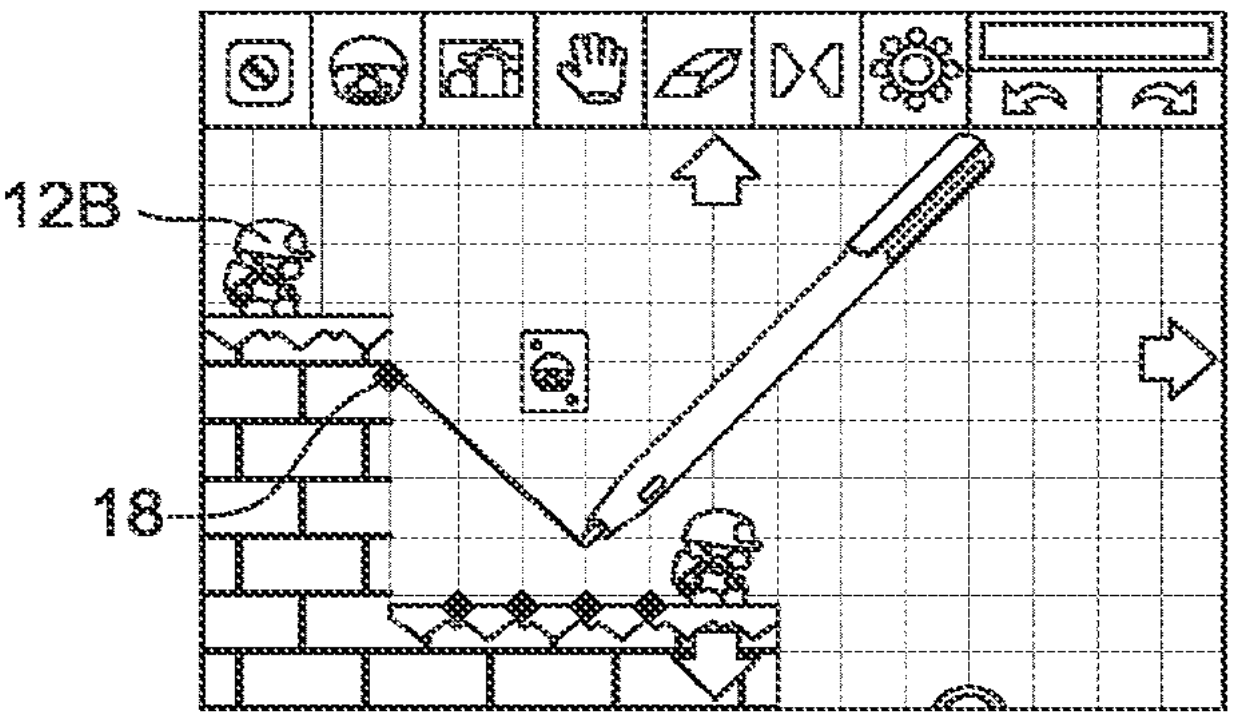
DETAILED DESCRIPTION FIG. 1is an illustrative example showing a user interacting with an exemplary editor program on a touch screen display according to certain example embodiments. A computing device1includes a display screen3. The display screen3also includes a touch screen with which a user interacts by using stylus2. In certain example embodiments, the display screen may be an ordinary display (e.g., a LCD, CRT, etc). Instead of, or in addition to, the stylus2, another type of user input may be used. For example, a keyboard, a mouse, a trackball, a touch pad, etc may be used to provide input into an editor program. FIGS. 2A-2Oshow illustrative views of interaction with the exemplary editor program shown inFIG. 1; FIGS. 2A-2Bshow example views that are presented to a user. Ground pieces are represented as bricks14. Game-play objects12A and12B are also displayed. The game-play objects may be selectable by stylus2. Arrows13are also displayed to facilitate viewing different parts of a layout if the layout is too big to be displayed on the user's display. For example, a user may operate the stylus2and press down on an area associated with the arrows13to cause the display to scroll in the direction of the arrow. FIG. 2Cshows a feature of the editor where a user may select different types of objects (e.g., via the stylus2) to place into the environment. Object15may be a selection that corresponds to the placement of slope terrain. Accordingly, in creating a new slope, the user selects point18with the stylus2inFIG. 2Dand draws a line with the stylus2to the valid point20. In connecting point18to point20with the drawn line, a slope is created from this valid connection. During the slope creation process terrain that matches the currently displayed terrain may be added to the newly created slope as shown inFIG. 2F. Such techniques for adding ...
DETAILED DESCRIPTION
FIG. 1is an illustrative example showing a user interacting with an exemplary editor program on a touch screen display according to certain example embodiments. A computing device1includes a display screen3. The display screen3also includes a touch screen with which a user interacts by using stylus2. In certain example embodiments, the display screen may be an ordinary display (e.g., a LCD, CRT, etc). Instead of, or in addition to, the stylus2, another type of user input may be used. For example, a keyboard, a mouse, a trackball, a touch pad, etc may be used to provide input into an editor program.
FIGS. 2A-2Oshow illustrative views of interaction with the exemplary editor program shown inFIG. 1;
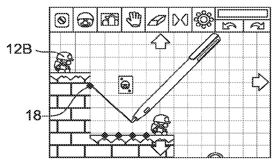
FIGS. 2A-2Bshow example views that are presented to a user. Ground pieces are represented as bricks14. Game-play objects12A and12B are also displayed. The game-play objects may be selectable by stylus2. Arrows13are also displayed to facilitate viewing different parts of a layout if the layout is too big to be displayed on the user's display. For example, a user may operate the stylus2and press down on an area associated with the arrows13to cause the display to scroll in the direction of the arrow.
FIG. 2Cshows a feature of the editor where a user may select different types of objects (e.g., via the stylus2) to place into the environment. Object15may be a selection that corresponds to the placement of slope terrain. Accordingly, in creating a new slope, the user selects point18with the stylus2inFIG. 2Dand draws a line with the stylus2to the valid point20. In connecting point18to point20with the drawn line, a slope is created from this valid connection. During the slope creation process terrain that matches the currently displayed terrain may be added to the newly created slope as shown inFIG. 2F. Such techniques for adding textures may be found in, for example, the U.S. Application entitled “METHOD AND APPARATUS FOR CONSTRUCTING VIRTUAL SLOPED LANDSCAPES IN COMPUTER GRAPHICS AND ANIMATION” (U.S. application Ser. No. 13/160,305), the entire contents of which are hereby incorporated by reference.
FIGS. 2G-2Jshow a similar technique for creating a slope below the game-play object12A (e.g., where the slope shown in the previousFIGS. 2A-2Fwas above the object12A).
After completing the slope creation described above, a user may then play a game based on the recently created environment. Accordingly, inFIG. 2K, a level is saved and a user may select to “play test” the level. InFIG. 2L, the level is loaded as a game. A user may then activate object12B (e.g., by tapping the object with the stylus) to cause the object to automatically move forward. Upon reaching the newly created slope, an animation is performed of the object sliding down the slope inFIG. 2M. Upon reaching the bottom of the first slope the object12B “hits” object12A to thereby cause the object12A to activate. Accordingly, both objects proceed forward and slide down the next slope inFIGS. 2N-2P. InFIG. 2Pthe objects reach a goal22.
FIG. 3shows an example user interface of an exemplary editor program according to certain example embodiments. A user may be presented with a layout100that includes different terrain and/or objects. In certain example embodiments, the layout may be a pre-configured layout that is saved into memory of a computing system and presented at the user's request. In certain example embodiments, the layout may initially be a blank screen that the user populates with terrain and/or objects. Thus, a user may create the layout by placing terrain into the layout. In certain example embodiments, the terrain may include “ground” terrain that may form a base layout.
FIG. 4shows example edit positions based on the layout shown inFIG. 3. Editable positions may be shown to a user by displaying a small circle around the editable position (e.g., position202). In certain example embodiments, the editable positions may be toggled on an off depending on an editing task currently being executed by a user of the editor program. For example, the task may be the creation of a slope (or slopes) between two or more editable positions. In certain example embodiments, the slops may be ground slops. Alternatively, the connections between the positions may be “bridges.”. In certain example embodiments, the editable positions may be the beginning or end of a slope.
As discussed above, a layout may include terrain and/or objects. In certain example embodiments, terrain may be a terrain “object” (e.g., in that terrain is one type of object). Further, in certain example embodiments, one type of a terrain object may be a “Ground Piece” object. A Ground Piece object may be designed to take up one square unit of a map or layout (e.g., a 2-dimensional map layout). In certain example embodiments, a ground piece may have dimensions for a virtual three-dimensional space.
Certain example embodiments may include criteria for determining the points on a layout that are valid edit points. As can be seen inFIG. 4, not all of the potential points are editable points. For example, points that are located at a vertex of a right may be prohibited from being “valid” edit points.
Certain example embodiments may include one or more of the following criteria for determining a valid “Slope Point” (e.g., a valid edit point for a slope): 1) a Slope Point may only attach to a Ground Piece object (e.g., as discussed above); and 2) only the top-left and top-right points of a Ground Piece object can be used as a Slope Point. In certain example embodiments, these restrictions may be put in place to avoid or prevent a slope from connecting to the base of a ground piece and creating undesirable collisions. However, in certain example embodiments, a bottom corner of a Ground Piece may be used when the proposed slope proceeds in a downward direction.
In certain example embodiments, a point may be determined to be an invalid point if the point touches a boundary edge of the layout map. For example, in a layout that is 20 by 20 units, a point at unit20may be determined to be an invalid slope point.
In certain example embodiments, a point may also be invalidated if it touches more than three ground pieces. For example, point302inFIG. 5touches more than 3 ground pieces (the lower-right, upper-right, and upper-left of three ground pieces.
In certain example embodiments, a point may be invalidated if there are no other possible connection points. For example, all points in a layout may be invalidated when all of the Ground Pieces are flat. Techniques for determining an invalid point are described in greater detail below. In certain example embodiments, a point may also be invalid because it already contains a slope.
FIG. 5shows example user actions for an exemplary editor program according to certain example embodiments. In the first example304ofFIG. 5, a user creates a valid connection between two valid slope points305aand305b. The two valid points are the top right and top left points of the respective ground pieces. As can be seen, these are valid slope points (e.g., based on the restrictions on slope points discussed above). Accordingly, a valid connection is created and results in the creation of a slope terrain between the two points. In the second example306ofFIG. 5, the point307ais the bottom right corner of the ground object. As discussed above, this situation may result in an invalid slope point. Accordingly, a slope between points307aand307bis not created. In the third example308ofFIG. 5, the slope point302, as discussed above, touches three different ground objects and is thus an invalid slope point.
FIG. 6shows example edit positions. Point402ais a potentially valid edit point. However, there are no corresponding points that is may connect too. Accordingly, in certain example embodiments, point402amay be designated as an invalid point or a point with no connection available. Also, point404touches 3 different Ground Pieces and is thus designated as an invalid slope point. The remaining points402b,402c,402d, and402eare valid edit points that a user may use as a basis for editing the existing terrain.
FIG. 7shows example edit positions of the exemplary editor program. Here, all of the dark spots are invalid edit points. The circled points are potential valid edit points. However, some of these points are rendered invalid because there are no possible connecting valid edit points. For example, while points502and504are not invalid per se, there are no corresponding points that these points may connect too. Accordingly, in certain example embodiments, a user editing the layout or terrain may not select these points for editing.
FIG. 8shows example valid edit positions that are available for editing based on the layout shown inFIG. 7. Note that, as discussed above, certain points that were not invalid are not shown inFIG. 8(e.g., points502and504). Accordingly, in certain example embodiments, a user may switch or turn on an editing mode and the shown points may become visible and available for slope creation.
FIGS. 9-11show an example placement of an object between two example editable points according to certain example embodiments. In certain example embodiments, slopes may be created between two editable points (e.g., slope points). In certain example embodiments, a user may select one of the editable points, for example, point702inFIG. 9may be selected. In certain example embodiments, the selection of a valid point may be done with a stylus via touch screen (e.g., touch panel2622inFIG. 27A). It will be appreciated that other techniques for selecting editable points may be used. For example, a mouse or a person's finger (e.g., through a touch screen) may be used to select a valid edit point. Certain example embodiments may use camera(s) and/or other types of sensors to sense the location or movement of a controller or a part of a person's body. This information may be translated to a computer to facilitate the selection of an editable point of the layout.
In any event, a user may select point702. In certain example embodiments, a selected point may be considered the start point of a yet to-be created slope. The selection of point702may cause only valid end points for slope creation to be displayed. As shown inFIG. 9, this may include points704and706. The remaining points may be grayed out (e.g., not selectable as an end-point) or removed from the display completely.
FIG. 10shows the user, after selecting point702, drawing a line802to point706. In certain example embodiments, the “drawing” may be accomplished by a user dragging a stylus across a touch screen. When the stylus is released above the valid end point706, the line802connects points702and706. After the connection is formed, the tiles (or tile portions) in the enclosed area902formed by ground pieces. Further, the line802is filled to form a slope between points702and706.FIG. 11shows the results of filling in the enclosed area902.
As a result of the newly added slope to the layout, the valid points that are editable (or not editable) are updated. Accordingly, for example, points904that were previously valid edit points are now changed to be invalid and thus hidden or not displayed to a user.
In certain example embodiments, a user may drag a line from a valid point to a position in the layout that contains no valid end point. In this case, when the user releases the stylus (or mouse, or other user input device) the slope creation process may be reset. For example, the previously selected beginning point may be automatically unselected. In certain example embodiments, the initially selected slope point may remain selected.
Certain example embodiments may include additional “rules” for the placement of slopes into an environment.FIGS. 12-14show example restrictions for placing objects between example editable points according to certain example embodiments. In certain example embodiments, one restriction may include placement of new slopes above existing slopes. One technique for accomplishing this may be through the use of a “shadow triangle. Accordingly, grid space that is occupied by the shadow triangle may be classified as “restricted” such that a slope may not be created through such an area.
FIG. 12shows a slope1002that has been created according to certain example embodiments. After creation of slope1002, a shadow triangle1004may be maintained, created, by an editor program. Based on the shadow triangle, space in the grid of the layout may be considered “restricted” such that no slopes may be created within the restricted space. The second picture inFIG. 12shows the restricted grid space1006in addition to the shadow triangle1004.
FIGS. 13 and 14show examples of shadow triangles and restricted space. For example based on a slope1102, a shadow triangle1104is created. This shadow triangle is associated with a restricted area1106. Similarly, inFIG. 14, slope area1202corresponds to shadow triangle1204. The restricted area1206is then created based on the shadow triangle1204.
In certain example embodiments, a shadow triangle may be extended to 2 grids vertically and 1 grid horizontally from a created slope. Other example embodiments may have different shadow triangle sizes (e.g., 1×1). In certain example embodiments, the shadow triangles may be used based on a world space coordinate system (e.g., in a three-dimensional world). However, whatever the technique used, certain portions of a layout may be classified as restricted.
In certain example embodiments, the nature of the restricted area may depend on the type of object that is being placed in the area. For example, terrain objects (e.g., Ground Pieces) may be restricted from the restricted area. However, other types of objects may be placed into the restricted area. For example, a virtual character or other type of virtual object may be placed into the area. The placement of these objects may be determined based on whether or not the object fits within the geometry of the area.
As discussed above, certain editable positions or points may be invalid for terrain modification purposes. In certain example embodiments, one condition may relate to the above discussed criteria for an editable point. The valid points may be further refined to discard those that have no valid connecting points.
FIG. 15shows potential combinations for a point1302. However, in certain example embodiments, when a line between the given edit point1302and another point intersects with a terrain block, the combination (e.g., attempted slope) is invalid. As can be seen inFIG. 15, point1302is invalid because there is no point above it, thus all the connections are either on the same level or down through the existing terrain geometry. This leads to determining that point1302is an invalid point.
Certain example embodiments may also use additional rules for determining valid points. As shown inFIG. 16, points1402,1404, and1406all have clear connections to other points. For example, an uninterrupted connection may be formed from points1404and1406to point1408. However, certain example embodiments may include an additional rule where a slop connection must be formed between connected terrain geometry that. Thus, points1404and1406may be determined to be invalid. In other words, for example, a slope may not be created between a floating island and a ground location. In certain example embodiments, the triangle that is drawn as a slope may not have the legs or “catheti” of the triangle exposed to non-terrain pieces (e.g., non Ground Pieces). Thus, referring toFIG. 16, a slope between point1404and1408would have the space below point1408empty. Such a slope would create a situation where the catheti of the triangle were exposed.
Alternatively, or in addition to, certain example embodiments may automatically fill in terrain that us “under” the slope” with additional ground pieces. In other embodiments the slope may be drawn “as is” without filling in the area below the slope.
Certain example embodiments, in addition to the terrain geometry or ground pieces, may include other types of objects. For example, a player character or an obstacle may be placed into the layout.
FIGS. 17-19show views of exemplary designs for an environment that includes an object according to certain example embodiments. A player character1502is placed into the display environment. Here, a user selects point1504. As explained above potentially valid points are then calculated based on the selected point. However, in this example, the object1502is present in the environment. Accordingly, a zone is created around the object1502to visually inform the user that the zone is a restricted area. In certain example embodiments, this zone may function similar to bounding box. Accordingly, slope lines (e.g., potential slope lines) that may intersect with this zone and their corresponding end points may be removed as selectable end points. In certain example embodiments, the end points may still be displayed, but may not be selectable. Alternatively, the end points may not be displayed or selectable. Thus, inFIG. 17point1506is removed as a potentially valid point. This leaves point1508as the only valid point that may form a slope with point1504. Accordingly, the user, inFIGS. 18-19, forms a connection between points1504and1508and a slope is created.
In certain example embodiments, an editing program may allow users to delete slopes.FIGS. 20-23show views of example actions for deleting terrain from an example environment. First,FIG. 20shows example slopes that have been created by a user, for example slope1802. In certain example embodiments, a user may be able to specify a portion of the environment to delete (e.g., erase). A user may specify a portion of slope1802. In certain example embodiments, this may, in turn, cause all of slope1802to be highlighted. An indication may be provided to the user as to the extent of the deletion that is to be performed. In certain example embodiments, a predetermined time period may be used before the deletion takes places. In the intervening time period, the user may cancel the operation. In certain example embodiments, the user may be asked to verify the deletion (e.g., by pressing or clicking a button). In either case, the slope1802may be deleted as shown inFIG. 21.
Another instance where a slope may be deleted may include where a ground piece that is adjacent to the slope is deleted. As noted above, certain example embodiments prohibit slopes where the legs of the slope triangle are exposed to “open” air or do not have a ground piece back them. Accordingly, as shown inFIG. 22, deletion of space2002may case the automatic deletion of slope area1802in addition to space2002as shown inFIG. 23.
FIG. 24shows an example prohibited action for creating terrain according to certain example embodiments. As explained above, creation of a slope between two points where the legs of the slope triangle are not backed by ground pieces may be prohibited. Thus, a slope between point2202and point2204may be prohibited because of the empty space that would exist beneath the slope.
FIGS. 25-26show another example prohibited terrain creation action according to certain example embodiments. Here another example is shown that creating a slope2400between point2402and point2404over another slope2302is a prohibited action.
In certain example embodiments, the creation of the environment through the editor allows a user to design new and interesting levels. The newly created environments may also be shared with other users. This may be done through local exchanges of disks or the like or may be done by transferring the newly created environments to other users over a network (e.g., the internet).
FIG. 27Ais a block diagram showing an internal structure of an exemplary computing apparatus according to certain example embodiments, which may be based on or comprise a conventional handheld computing device such as a Nintendo DS™ or DSi™ video game system. Electronic circuit board2640may be disposed in a housing. Electronic circuit board2640may have a CPU core2642mounted thereon. CPU core2642may be connected to bus44. Bus2644facilitates the transfer of data between the connected components.
Connector2646connects to bus2644. Cartridge2628may be detachably connectable to connector2646. Cartridge2628may be a memory medium for the storage of data that may be accessible to system2600when cartridge2628is mated to connector2646. Cartridge2628may include a nonvolatile semiconductor memory such as a ROM or a flash memory. Other medium types for storing data may also be used such as, for example, a CD-ROM, a DVD, or a similar optical memory medium.
Cartridge2628might comprise a SD card or similar non-transitory memory medium, or may be split into discrete memory types. First, cartridge2628may have “read only memory” or ROM2628afor storing application or static data. Such data may include, for example, environment templates or other type of program information that is to be displayed on system2600. Cartridge2628may also optionally include RAM2628bfor rewritably storing backup or application data thereon. Such writable data may include, for example, options specific to a given environment template, saved environments created by a user that are stored in ROM2628a, or other types of information created by a user (or the system2600). Other implementations can use entirely embedded memory.
An editor program for environments may be stored in ROM2628ain cartridge2628or in internal flash memory is loaded into main RAM2648and executed by CPU core2642. Temporary data and data for generating an image which are obtained by the CPU core2642through execution of the application are stored in the main RAM2648.
As described above, ROM2628astores an application, which is a group of instructions and a group of data in the format executable by the system2600, especially by CPU core2642. The application is read into and executed by main RAM2648when necessary. In this embodiment, the application and the like are recorded in the cartridge2628, but the application and the like may be supplied by another medium (e.g., alternative storage) or via a communication network (e.g., a downloadable program).
Internal storage2664may also be included in system2600. Similar to cartridge2628, internal storage2664may store data. This data may include application software (e.g., programs) or application data (e.g., content). Internal storage2664may be flash memory or other similar nonvolatile memory for data storage. Data may be read from and written to storage2664as needed by system2600.
A first GPU2650is connected to a first video RAM (hereinafter, referred to the “VRAM”)2656, and the second GPU2652is connected to a second VRAM2658. In accordance with an instruction from CPU core2642, the first GPU2650renders image data based on data for generating an image stored in main RAM2648. The rendered image data from the first GPU2650may be stored in the first VRAM2656. In accordance with an instruction from CPU core2642, the second GPU2652renders image data based on data for generating an image stored in main RAM2648. The rendered image data from the second GPU2652may be stored in the second VRAM2658.
The first VRAM2656and the second VRAM2658are connected to LCD controller2660. LCD controller2660includes register2662, and register2662consists of, for example, one bit, and stores a value of “0” or “1” (data value) according to an instruction of CPU core2642. LCD controller2660outputs the screen data rendered in the first VRAM2656to the first LCD2602, and outputs the screen data rendered in the second VRAM2658to the second LCD2604in a case that the data value of the register2662is “0”. Furthermore, LCD controller2660outputs the screen data rendered in the first VRAM2656to the second LCD2604, and outputs the screen data rendered in the second VRAM2658to the first LCD2602in a case that the data value of register62is “1”. It is noted that in the interests of simplicity, “0” is constantly stored in register2662in this exemplary illustrative embodiment.
An I/F circuit is a circuit for exchanging data between external input/output devices. InFIG. 27AI/F circuit2654is connected to touch panel2622, operating switches2620(e.g., that interface with buttons of system2600), speaker2632, Wi-Fi adapter2633, and microphone2666. Touch panel2622may be located in the same area as the second LCD2604. Operating switches2620may communicate with the buttons and switches. Speaker2632may provide audio output and microphone2666may provide audio input.
Wi-Fi adapter2633may be included to system2600to communicate with external network and thus facilitate network enabled features on the system2600. For example a user may upload or download environments. Wi-Fi adapter2633may be a wireless adapter that supports 802.11b, 802.11g, or 802.11n. Alternatively, WiFi adapter2633may instead by a wired adapter that would use, for example, a wired Ethernet connection through a RJ 45 or other port.
Touch panel2622may have a coordinate system corresponding to the coordinate system of the second VRAM2658and may output coordinate position data corresponding to the position which is input (e.g., indicated) by a stylus or the like. The resolution of the touch panel may correspond to the resolution of the second LCD2604. For example, the resolution of the second LCD2604may be 256 dots by 192 dots, and then the precision of touch panel2622would be 256 dots by 192 dots. Alternatively, the precision of the touch panel may be higher or lower than the precision of the second LCD. Further, another touch panel may be added to system2600that corresponds to the first LCD2602. Alternatively, touch panel2622may correspond to the first LCD2602.
In certain example embodiments, the editing of an environment may occur on a personal computer (e.g., a desktop).FIG. 27Bshows an example computing system for implementing the techniques described herein.
FIG. 27Bis an example processing system configured to implement an editor system according to certain example embodiments. Processing system2750may include CPU2758. The CPU2758may communicate with RAM2756, storage medium2760of a system bus2770. Processing system2750may facilitate user input through a user input adapter2754and user input2752. For example, user input for controlling or providing input to an editor program may be provided through a keyboard, mouse, touch screen, or the like. Processing system may also provide an output through display interface2764to display2762(e.g., an LCD or other similar display device). The display2762and user input2752may be provided in the same device. For example a touch screen may be provided proximate to the display.
In certain example embodiments, processing system2750may also include a network interface2766, such as, for example, an Ethernet card that provides wired or wireless connectivity to external resources. This may facilitate communication between the processing system2750and an external system2768. External system2768may be another processing system (e.g., similar to processing system2750) that stores levels that have been created by other users. Thus, in certain example embodiments, the levels may be shared between users via the communication connection.
FIG. 28is an example flow chart showing an exemplary process for creating a slope in an environment according to certain example embodiments. Based on an existing environment, a number of valid start points may be displayed to a user in step2702. Based on the displayed start points a user may perform a selection of one of the valid start points and relay the selection to a computer in step2704. Based on the user selected start point, the valid end points for that start point may be determined in step2706. These valid end points may be displayed to the user. The user may then perform a dragging operation (e.g., by moving a stylus or moving a mouse) across the environment. During this the display may be updated in step2708to reflect the path that a potential slope may take. A user may perform a selection of a valid end point in step2710. Based on a received end point and the previously selected start point a line may be drawn between the two points in step2712. This line may provisionally indicate the nature of the slope that is being created. After this, the slope may be fully created in step2714by filling in the area that is to be enclosed.
Further, as described, herein, various other steps may be added. For example, a texture may be subsequently added to the newly created slope. Furthermore, additional checks may be performed on the connection between start and end point (e.g., with respect to game objects in the environment). In any event, a new slope may be created and displayed to a user.
FIG. 29is an illustrative flow chart showing an example process for deleting a slope from the environment. In certain example embodiments, a user may select a delete option from an editor. For example, an eraser tool may be selected by the user. The user may issue a command to delete a section of the environment in step2802. After receiving this command, the computing system may perform two checks. First, in step2804the system may check to see if the indicated portion is within the triangle of a slope. Second, a check may be performed to see if the deleted portion is adjacent to a slope portion in step2806. This may include checking if the deleted portion is adjacent to the legs of the slope triangle. If the checks in steps2804or2806are successful, then the slope is to be deleted. Accordingly, in step2808the slope area is highlighted. In the case were an adjacent portion of the environment is being deleted in addition to slope area, this portion may be additionally highlighted. The highlighting may act to inform a user of the nature of the deletion procedure. For example, a user may not realize that deleting a portion of the environment that is adjacent to the slope may also cause the slope to be deleted. In such a situation, there may be an additional check that asks the user to verify the deletion process (e.g., by clicking an “okay” box). After the area to be deleted is highlighted and/or the user confirms the deletion, the slope area (and the adjacent area) may be deleted in step2810.
Certain example embodiments may include additional steps to those described above. Furthermore, some of the steps may be skipped. For example, the highlighting of the sloped area may be skipped and the area may simply be deleted based on the user's command.
While the technology herein has been described in connection with exemplary illustrative non-limiting embodiments, the invention is not to be limited by the disclosure. For example, the techniques herein may be applied to picture editing where certain portions of the image are classified according to color or depth in the image. The invention is intended to be defined by the claims and to cover all corresponding and equivalent arrangements whether or not specifically disclosed herein.
Claims
- A computer implemented method for designing virtual structures that are to be traversed by animated game characters in a virtual environment, the virtual environment including existing virtual structure, the method comprising: receiving, via an input device coupled to a computing system, a first input;selecting, based on the first input, a start point from among a plurality of connection points that are associated with an existing virtual structure to begin a new virtual structure;responsive to selection of the start point, determining and displaying at least one valid end point from among the plurality of connection points based on the start point wherein each of the valid end points form a connection of the new virtual structure from the valid end point to the selected start point such that the new virtual structure that would be created based on the connection does not intersect with the existing virtual structure;after selecting the start point, receiving a second input and selecting an end point from among the determined and displayed at least one valid end point based on the second input, the selected start point and the selected end point forming a valid connection of the new virtual structure between two portions of the existing virtual structure of the virtual environment;incorporating the new virtual structure into the virtual environment between the two portions of the existing virtual structure in accordance with the selection of the start point and selection of the end point;and outputting the virtual environment that includes the incorporated new virtual structure to a display.
- The method of claim 1 , further comprising: receiving, via the input device coupled to a computing system, a user selection of a delete position that relates to a portion of the virtual environment that is to be deleted;determining if the delete position is located within the new virtual structure;and updating the virtual environment to remove the new virtual structure based on the determination that the delete position is within the new virtual structure.
- The method of claim 1 , further comprising: determining if a delete position is located outside, yet proximate to, the new virtual structure;and updating the virtual environment to remove existing environmental structure based on the delete position, updating the virtual environment to remove the new virtual structure based on the determination that the delete position is proximate to the new virtual structure and the removal of the existing environmental structure.
- The method of claim 1 , wherein determination of the at least one valid end point includes a criteria of the start point and the at least one valid end point being on the same contiguous structure in the virtual environment.
- The method of claim 1 , wherein determination of the at least one valid end point includes a criteria that the start point and the at least one valid end point are vertexes of a right angle triangle that backs contiguous structure in the virtual environment.
- The method of claim 5 , wherein right angle triangles with catheti not backed by terrain are not valid end points.
- The method of claim 1 , further comprising: initially setting the plurality of connection points from which the start point may be selected by removing connection points that have no possible valid end point for connection therewith.
- A non-transitory storage medium storing instructions for modifying and/or creating a virtual world displayed, at least in part, on a display device of a computing system that includes at least one processor coupled to a memory device, the virtual world including existing virtual structure to be traversed by animated game characters, the virtual structure associated with a plurality of connection points for creating new virtual structure, the stored instructions comprising instructions configured to cause the computing system to: accept, via an input device coupled to the computing system, a first input;select, based on the first input, a start point from among a plurality of connection points that are associated with the existing virtual structure to begin a new virtual structure;responsive to selection of the start point, determine and display at least one valid end point from among the plurality of connection points based on the start point wherein each of the valid end points form a connection of the new virtual structure from the valid end point to the selected start point such that the new virtual structure that would be created based on the connection does not intersect with the existing virtual structure;after selection of the start point, accept a second input and select an end point from among the determined and displayed at least one valid end point based on the second input, the selected start point and the selected end point forming a valid connection of the new virtual structure between two portions of the existing virtual structure of the virtual world;generate and add the new virtual structure into the virtual world between the two portions of the existing virtual structure in accordance with the selection of the start point and selection of the end point;and output a view of the virtual world that includes the incorporated new virtual structure to the display device.
- The medium of claim 8 , wherein the stored instructions further comprise instructions that are configured to cause the computing system to: accept, via the input device coupled to a computing system, a user selection of a delete position that relates to a portion of the virtual world t that is to be deleted;determine if the delete position is located within the new virtual structure;and update the virtual world to remove the new virtual structure based on the determination that the delete position is within the new virtual structure.
- The medium of claim 8 , wherein the stored instructions further comprise instructions that are configured to cause the computing system to: determine if a delete position is located outside, yet proximate to, the new virtual structure;and update the virtual world to remove existing environmental structure based on the delete position;and update the virtual world to remove the new virtual structure based on the determination that the delete position is proximate to the new virtual structure and the removal of the existing environmental structure.
- The medium of claim 8 , wherein determination of the at least one valid end point includes a criteria of the start point and the at least one valid end point being on the same contiguous structure in the virtual world.
- The medium of claim 8 , wherein the stored instructions further comprise instructions that are configured to cause the computing system to: initially set the plurality of connection points from which the start point may be selected by removing connection points that have no possible valid end point for connection therewith.
- A computing apparatus for designing a virtual environment to include new visible structural elements, the virtual environment including existing virtual structure to be traversed by animated game characters, the computing apparatus comprising: a user input device configured to accept a first input and a second input;and a processing system that includes at least one processing circuit coupled to a memory device and the user input device, the processing system configured to: select, based on the first input, a start point from among a plurality of connection points that are associated with the existing virtual structure to begin a new virtual structure;responsive to selection of the start point, determine and display at least one valid end point from among the plurality of connection points based on the start point wherein each of the valid end points form a connection of the new virtual structure from the valid end point to the selected start point such that the new virtual structure that would be created based on the connection does not intersect with the existing virtual structure;after selection of the start point, accept the second input and select an end point from among the determined and displayed at least one valid end point based on the second input, the selected start point and the selected end point forming a valid connection of the new virtual structure between two portions of the existing virtual structure of the virtual environment;incorporate the new virtual structure into the virtual environment between the two portions of the existing virtual structure in accordance with the selection of the start point and selection of the end point;and output the virtual environment that includes the incorporated new virtual structure to a display device.
- The computing apparatus of claim 13 , wherein the processing system is further configured to: accept, via an input device coupled to a computing system, a user selection of a delete position that relates to a portion of the virtual environment that is to be deleted;determine if the delete position is located within the new virtual structure;and update the virtual environment to remove the new virtual structure based on the determination that the delete position is within the new virtual structure.
- The computing apparatus of claim 13 , wherein the processing system is further configured to: determine if a delete position is located outside, yet proximate to, the new virtual structure;and update the virtual environment to remove existing environmental structure based on the delete position;and update the virtual environment to remove the new virtual structure based on the determination that the delete position is proximate to the new virtual structure and the removal of the existing environmental structure.
- The computing apparatus of claim 13 , wherein determination of the at least one valid end point includes a criteria of the start point and the at least one valid end point being on the same contiguous structure in the virtual environment.
- The computing apparatus of claim 13 , wherein the processing system is further configured to: initially set the plurality of connection points from which the start point may be selected by removing connection points that have no possible valid end point for connection therewith.
Disclaimer: Data collected from the USPTO and may be malformed, incomplete, and/or otherwise inaccurate.