U.S. Pat. No. 9,808,713
GAME CONTROLLER WITH STRUCTURAL BRIDGE
AssigneeWikipad, Inc.
Issue DateJuly 28, 2017
Nintendo Escapes Vice Grip in ITC Challenge
Certain Portable Gaming Console Systems with Attachable Handheld Controllers and Components Thereof
United States International Trade Commission
Inv. No. 337-TA-1111

This ITC Investigation involved allegations that the Nintendo Switch allegedly infringed two Gamevice patents (U.S. Patent Nos. 9,808,713 and 9,855,498) relating to handheld gaming devices with detachable controllers. The ITC’s final ruling followed a prior Administrative Law Judge (“ALJ”) ruling that found that Nintendo did not infringe Gamevice’s patents.
The Commission’s final ruling affirmed the ALJ’s findings on noninfringement. The ITC also found that claim 10 of the ’713 patent was invalid. The ITC further found that Gamevice was unable to prove that its products utilize the ’713 patent in a way that satisfies the ITC’s domestic industry requirement.
Illustrative Figure
Abstract
A device directed to a combination computing and input device. The computing device providing a plurality of sides, each of the plurality of sides are disposed between an electronic display screen and a back of the computing device. The input device communicates with the computing device and provides a pair of control modules adjacent to and confining the computing device on at least two opposing sides of the computing device. The input device further provides a structural bridge securing the pair of control modules one to the other, and a touch sensitive input module. The structural bridge adaptively and snugly accommodate the length of the computing device. A first of the pair of control modules features a retention mechanism communicating with the structural bridge. The retention mechanism adaptively secures the structural bridge such that the pair of control modules snugly accommodate the length of the computing device.
Description
DETAILED DESCRIPTION The present disclosure generally relates to a combination game controller and information input device directed to controlling electronic games and entry of information to a computing device, also referred to herein as video games, computer and applications games. The apparatus preferably includes a computing device, an electronic game communicating with the computing device, and an input device for controlling movement of a virtual object provided by the electronic game, and entry of information into the computing device. In a preferred embodiment, the input device includes a pair of opposing side structures adjacent opposing sides of plurality of sides of the computing device. The input device further preferably includes a plurality of input switches, wherein said input switches are adjacent each of the at least two opposing sides of the plurality of sides of the computing device, and a bridge structure disposed between the pair of sides to form a three sided structure. The third structure mitigates inadvertent removal of the computing device from the three sided structure when the computing device is fully nested within the three sided structure. Turning to the drawings,FIG. 1provides an exemplary game controller and information entry device (“G&D”)100capable of being used in accordance with various embodiments of the present invention. The exemplary G&D100has at least a computing device102(also referred to herein as a computing device102), which provides a plurality of sides, such as104,106,108, and126. Each of the plurality of sides104,106, and108are disposed between an electronic display screen110, of the computing device102, and a back112(shown byFIG. 2) of the computing device102operates. The G&D100further preferably includes an input device114. The computing device102may take the form of a tablet computer, smart phone, notebook computer, or other portable computing device, In a preferred embodiment, the input device114provides a pair of side structures,116and118, with a bridge structure115disposed there ...
DETAILED DESCRIPTION
The present disclosure generally relates to a combination game controller and information input device directed to controlling electronic games and entry of information to a computing device, also referred to herein as video games, computer and applications games. The apparatus preferably includes a computing device, an electronic game communicating with the computing device, and an input device for controlling movement of a virtual object provided by the electronic game, and entry of information into the computing device. In a preferred embodiment, the input device includes a pair of opposing side structures adjacent opposing sides of plurality of sides of the computing device. The input device further preferably includes a plurality of input switches, wherein said input switches are adjacent each of the at least two opposing sides of the plurality of sides of the computing device, and a bridge structure disposed between the pair of sides to form a three sided structure. The third structure mitigates inadvertent removal of the computing device from the three sided structure when the computing device is fully nested within the three sided structure.
Turning to the drawings,FIG. 1provides an exemplary game controller and information entry device (“G&D”)100capable of being used in accordance with various embodiments of the present invention. The exemplary G&D100has at least a computing device102(also referred to herein as a computing device102), which provides a plurality of sides, such as104,106,108, and126. Each of the plurality of sides104,106, and108are disposed between an electronic display screen110, of the computing device102, and a back112(shown byFIG. 2) of the computing device102operates. The G&D100further preferably includes an input device114. The computing device102may take the form of a tablet computer, smart phone, notebook computer, or other portable computing device,
In a preferred embodiment, the input device114provides a pair of side structures,116and118, with a bridge structure115disposed there between. One of the pair of side structures, for example116, is adjacent to and confines the computing device102on a first side, such as104of the plurality of sides104,106,108, and126of the computing device102. The second side structure of the pair of side structures, such as118, is adjacent to and confines the computing device102on a second side, such as108, of the plurality of sides104,106,108, and126of the computing device102, wherein the first and second sides, such as104and108, of the plurality of sides104,106,108, and126of the computing device102are opposing sides of the plurality of sides104,106,108, and126, of the computing device102.
In a preferred embodiment, the input device114further provides a plurality of removable game control modules120and122, wherein the removable game control modules120and122are adjacent each of the at least two opposing sides104and108, of the plurality of sides104,106,108, and126, of the computing device102, and a bridge structure124, disposed between the pair of side structures116and118, and adjacent the third side126, of the plurality of sides104,106,108, and126, of the computing device102.
In a preferred embodiment, the removable game control modules120and122may be removed from the input device114, and replaced by removable keyboard modules164and166, ofFIG. 8. To facilitate the exchange of modules, the input device preferably provides a pair of input module apertures170. The removable keyboard modules collectively form a full function keyboard and each provide an auxiliary electronic display screen (“ADS”)168, each ADS168having at least the functionality of the electronic display screen110.
In an alternate embodiment, shown byFIG. 10, the removable keyboard modules164and166are a pair of touch responsive electronic display screens172and174, each of the touch responsive electronic display screens having at least the functionality of the electronic display screen110, include the functionality of a mouse pad portions176and178, and selectively presents keys of a keyboard180and182for information entry. Preferably, the keys are virtual keys that respond to a touch by a user.
Returning toFIG. 1, preferably, the bridge structure124in combination with the pair of side structures116and118form a three sided structure128(ofFIG. 5) (also referred to herein as a u-shaped structure128of the input device114), in which the computing device102nests, such that the computing device102is confined by the u-shaped structure128, and the u-shaped structure128mitigates inadvertent removal of the computing device102from the u-shaped structure128when the computing device102is fully nested within the three sided structure128.
The G&D100ofFIG. 1, further preferably includes a video game130.
Preferably, the video game130provides a virtual object132displayed by the electronic display screen110, the virtual object132is responsive to input from the input device114. An example of a response of the virtual object132would be movement of the virtual object132, or the loading of an alternate computer game, based on a predetermined signal provided by the input device114, or an appearance of a character. It is noted thatFIG. 1displays the housings of the plurality of switches, whereas at least some of the plurality of switches are shown in the partial cutaway ofFIG. 3.
FIG. 2depicts and reveals the back112of the computing device102. Further shown byFIG. 2, is the input device114, which provides a pair of trigger switches136and138, supported by their corresponding side structures116and118respectively.
FIG. 3shows that a predetermined number of the plurality of switches140, collaborate with each other to form an input apparatus142, the input apparatus142controls display of virtual objects displayed on the electronic display screen110of the computing device102. Preferably, the input apparatus142is a joystick142.FIG. 3further shows that the input device114provides a plurality of buttons144and119of the removable game control modules120, which activate corresponding switches145and121. The main function of the trigger138, the joystick142, and the buttons144and119of the removable game control modules120is to govern the movement/actions of a playable body/object or otherwise influence events in a video game130(ofFIG. 1) or an alternate computer game.
FIG. 4shows the G&D100, further includes a second joystick146, and a second button148, which are provided on the side structure116, adjacent the trigger136. WhileFIG. 5shows the central processing unit (CPU)150, of the input device114.
FIG. 6shows the input device114includes the CPU150, interacting with the plurality of switches152, which preferably include at least switches119of the removable game control modules120(ofFIG. 1), switches117of the removable game control modules122(ofFIG. 1),136,138,142,144,146, and148(ofFIGS. 2 and 3).FIG. 6further shows the input device114includes a communications protocol154providing the communication link between the computing device102, and the input device114. In a preferred embodiment, a Universal Serial Bus (USB) communications protocol is utilized. However, as those skilled in the art will recognize, the communications protocol154is not limited to a USB protocol.
FIG. 6further shows that the computing device102preferably includes at least a CPU156, interacting with the electronic display screen110, the video game130, a device driver158, which facilitates the interaction between the computing device102and the input device114, and a communications protocol160providing the communication link between the computing device102, and the input device114. In a preferred embodiment, a Universal Serial Bus (USB) communications protocol is utilized. However, as those skilled in the art will recognize, the communications protocol160is not limited to a USB protocol.
FIG. 7shows an alternative embodiment of an exemplary game controller162, in which the device driver158and the video game130are located in the input device114.
FIG. 8shows in a preferred embodiment, the G&D100includes a first camera184, on a first side of the computing device102, a second camera186, on the back side of the computing device102(shown byFIG. 9), a third camera188on a first side of the input device114, and a fourth camera190on the back side of the input device114(shown byFIG. 9).
In a preferred embodiment, each of the four cameras may selectively function independently, or may be used in conjunction with one another, and each of the four cameras184,186,188, and190are fully functional in capturing still and video images. Additionally, and preferably, the first and second cameras184and186are fully operative, even when the computing device102is detached from the input device114, while the third and fourth cameras188and190are fully functional, even when the input device114is detached from the computing device102.
In a preferred embodiment, when the computing device102is nested in the input device114, the first and second cameras,184and186, are responsive, either independently or simultaneously, to input from either the computing device102, or the input device114, depending on which device is selected for control of the first and second cameras,184and186. Further, in the preferred embodiment, each the computing device102and the input device114, are configured with a Bluetooth protocol stack communication feature, which permits the user to operate the first and second cameras,184and186, of the computing device102with the input device114, even when the computing device102is detached from the input device114. Likewise, when the computing device102and the input device114are configured with a Bluetooth protocol stack communication feature, the user may operate the third and fourth cameras,188and190, of the input device114, using the computing device102. In other words, in the preferred embodiment, each of the four cameras184,186,188, and190, may be selectively operated, individually or collectively, whether or not the computing device102is nested within the input device114.
FIG. 9shows that in a preferred embodiment, the input device114includes an auxiliary power source192, and an auxiliary data storage device194, which preferably includes a cache portion196. Preferably, the auxiliary power source192is a lithium ion battery, which provides power to the input device114, and the computing device102, when the power source of the computing device102is depilated; and the auxiliary data storage device194is a solid state hard drive.
In the preferred embodiment, the cache196is sized to buffer synchronized input from each of the cameras184,186,188, and190, such that the auxiliary data storage device194may store and retrieve images, still or video, for display seamlessly, including a simultaneous output of video images recorded by each of the cameras184,186,188, and190.
In a non-limiting exemplary application of utilizing the cameras184,186,188, and190, the first camera184could be trained on an information presenter, while the second camera186is trained on a portion of an audience attending the presentation. The third camera188could be trained on a screen used by the presenter for presenting their information to the audience, while the fourth camera is trained on an alternate portion of the audience. By simultaneously replaying the recorded presentation, a response of the audience to the information, and sequence of information being presented, may be analyzed for fostering improvements to the presentation.
FIG. 11shows an alternative embodiment of a video game controller200, which provides an integrated transaction card input feature202. Preferably, the integrated transaction card input feature202, includes a transaction card slot204, and a transaction card reader206. In a preferred embodiment, the transaction card reader206is a magnetic strip reader, but as those skilled in the art will recognize, the transaction card reader can be, in the alternate: is an optical character recognition reader; a barcode reader; an object recognition reader, or a pattern recognition reader.
FIG. 12shows that in a preferred embodiment, a combination computing device and electronic game controller with an integrated point of sale device210preferably includes a computing device212, having a plurality of sides214, each of the plurality of sides214, are disposed between an electronic display screen216, of the computing device and a back218of the computing device, and an input device220, in electronic communication with the computing device212. The input device220preferably provides side structures222, adjacent to and confining the computing device on at least two opposing sides of the plurality of sides214of the computing device212. The input device220, further preferably provides input module apertures224, each input module aperture224, selectively accepts either a game control module, such as102and122ofFIG. 1, or a removable keyboard module, such as226and228. Preferably, the input module apertures224are adjacent each of the at least two opposing sides of the plurality of sides214of the computing device212.
FIG. 12further shows that in a preferred embodiment, the combination computing device and electronic game controller with an integrated point of sale device210preferably includes a camera230, communicating with each the input device220, and the computing device212. The camera230, selectively captures either still or video images, and that the input device220, further provides an integrated transaction card input feature232, which interacts with a transaction card234, and that preferably, the input device is an electronic game controller220. Preferably, the camera230is a first camera, having a lens facing the user while the user is facing the electronic display screen216, and includes at least a second camera, such as186or190(ofFIG. 9), having a lens facing in a direction opposite that of the first camera184.
FIG. 12additionally shows an application236, displayed on the electronic display screen216, of the computing device212. Preferably, the application236, displayed on the electronic display screen216of the computing device212, is a point of sale transactional computer application, which interacts with the electronic game controller220and the computing device212.
FIG. 13shows an alternative embodiment of a combination computing device and electronic game control240(also referred to herein as a device240). The computing device242, preferably provides a plurality of sides244, each of the plurality of sides are disposed between an electronic display screen246, of the computing device242, and a back248of the computing device242.
Preferably, the electronic game controller250(also referred to herein as input device250), is in electronic communication with the computing device242. Preferably, the input device250provides a pair of control modules252. The pair of control modules252, are adjacent to and confining the computing device242, on at least two opposing sides of the plurality of sides244, of the computing device242. The pair of control modules252preferably provide input module apertures254, each input module aperture254, secures an instructional input device256. Preferably, the input module apertures254are adjacent each of the at least two opposing sides of the plurality of sides244, of the computing device242.
FIG. 14shows the back248, of the computing device242, and the computing device242, partially positioned within the input device250.FIG. 14further shows a structural bridge258, securing the pair of control modules252, one to the other, and communicating with the back248, of the computing device242, at a mid-region260, of the back248, of the computing device242.
FIG. 14further shows that the pair of control modules252provide a confinement boss262, and the confinement boss262provides a fastening detent264. The fastening detent264interacts with a retention member266, to secure the structural bridge258, to the pair of control modules252. In a preferred embodiment, the retention member266is responsive to a catch268, which preferably is a spring activated catch268, and the retention member268is preferably a spring loaded retention member268. Still further,FIG. 14shows that in a preferred embodiment, the structural bridge258provides a communication link270, which passing signals between the pair of control modules252.
Continuing withFIG. 14, in a preferred embodiment, the communication link270, provides a communication module272, and in the alternative, provides a signal pathway274, for use in passing signals between the pair of control modules252. In a preferred embodiment, the communication module272is a wireless communication module272, which operates in a frequency range of 2.4 GHz. In an alternate preferred embodiment, the wireless communication module272is a personal area network. As those skilled in the art, a personal area network (PAN) is a computer network used for communication among computerized devices, including telephones and personal digital assistants. PANs can be used for communication among the personal devices themselves (intrapersonal communication), or for connecting to a higher level network and the Internet (an uplink). A wireless personal area network (WPAN) is a PAN carried over wireless network technologies such as IrDA, Bluetooth, Wireless USB, Z-Wave, ZigBee, or even Body Area Network. The reach of a WPAN varies from a few centimeters to a few meters. A PAN may also be carried over wired computer buses such as USB and FireWire.
In an embodiment that utilizes the signal pathway274, as the communication link, the signal pathway274may be in the form of a metallic conductor, a fiber optic conductor, a conductive polymer, or the conductive layer of a flex circuit. The skilled artisan will further appreciate that the structural bridge258(ofFIG. 14), or276(ofFIG. 15) may be either formed from a ridged material, such as a ridged polymer, or from a flexible material, such as a flexible polymer. In a preferred embodiment, when a flexible material is selected, and the signal pathway274is a wired pathway, the signal pathway274may be coupled externally to the structural bridge276, as shown byFIG. 15.
FIG. 15further shows that in a preferred embodiment, the instructional input device256, may be an electronic game control module278(which may be either removable, or fixed), or a keyboard module280(ofFIG. 13, which may be either removable, or fixed).
FIG. 16shows a back plan view of an alternative combination300, which preferably includes, but is not limited to, a computing device302that provides a plurality of sides304, each of the plurality of sides are disposed between an electronic display screen306(ofFIG. 13) of the computing device and a back308of the computing device302. Preferably, the alternative combination300further includes a communication port310, interacting with the computing device302. In a preferred embodiment, the communication port310provides a communication link312(which for purposes of illustration is shown as a wired connection314, but will be understood to be a wireless connection in an alternative embodiment). Preferably, the communication port310further provides a pair of confinement structures316, the pair of confinement structures316, which are preferably adjacent to and confining the computing device302on at least two opposing sides of the plurality of sides304of the computing device302.
The alternative combination300, further preferably includes an input device318(also referred to herein as input device114), attached to and in electronic communication with the communication port310. The input device318providing a pair of control modules252, the pair of control modules252providing input module apertures224(ofFIG. 12), each input module aperture224secures an instructional input device356(ofFIG. 23), or such as120ofFIG. 11, or256ofFIG. 13. Preferably, the input module apertures224, are adjacent each of the at least two opposing sides of the plurality of sides304, of the computing device302, and wherein the input device356, or such as120ofFIG. 11, or256ofFIG. 13, is a separate and distinct structure from the communication port310, forming no structural portion of the communication port310.
FIG. 16further shows that in a preferred embodiment, the communication port310further includes a fastening mechanism320. In one embodiment, a soft draw latch, such as that provided by Southco, of 210 N. Brinton Lake Road Concordville, P.A. 19331, have been shown to be a useful fastening mechanism320.
FIG. 17shows a top view of the communication port310that preferably includes a structural bridge322, securing the pair of confinement structures316, one to the other. The structural bridge322is preferably secured to a select confinement structure of the pair of confinement structures316by way of a solid connection324, and to remaining confinement structure of the pair of confinement structures316by way of a slip fit326. The fastening mechanism320, is preferably securely fastened to to a conduit328, of the structural bridge322, by way of a anchor member330, the anchor member330is preferably positioned in a location adjacent the slip fit326, and by way of an attachment member332(shown inFIG. 18), securely attached to the remaining confinement structure of the pair of confinement structures316. The attachment member332is preferably positioned in a location adjacent the slip fit326. Operation of the fastening mechanism320facilitates an expand and contract of the distance between the pair of confinement structures316. The expansion and contraction of the distance between the pair of confinement structures316, facilitates placement of the computing device302between the pair of confinement structures316, the application of sufficient compressive load being placed on the computing device302to securely hold the computing device between the pair of confinement structures316, and an ability to remove the compressive load and allow removal of the computing device from the communication port310.
FIG. 17further shows that each of the pair of confinement structures316, provide a pair of controller docking pins334, whileFIG. 18shows that each of the pair of confinement structures316further provide a computing device cradle336, and that a select confinement structure of the pair of confinement structures316provides a computing device interface feature338. The interface feature338, facilitates at least, but not limited to, the provision of power to the computing device302.
FIG. 19shows a front view340, of a first selected confinement structure of the pair of confinement structures316, which reveals a plurality of signal input lands342for use in receiving signals from the input device318, ofFIG. 16, and the pair of controller docking pins334.
Further shown byFIG. 19, is a back view344of the first selected confinement structure of the pair of confinement structures316, which reveals computing device interface feature338, the computing device cradle336, and the slip fit326.
FIG. 20shows a front view346, of a second selected confinement structure of the pair of confinement structures316, which reveals a plurality of signal input lands342for use in receiving signals from the input device318, ofFIG. 16, and the pair of controller docking pins334.
Further shown byFIG. 20, is a back view348of the second selected confinement structure of the pair of confinement structures316, which reveals, the computing device cradle336, and the solid connection324.
FIG. 21reveals, for purposes of disclosure and for consistency of views with remaining disclosed figures of an embodiment, a bottom right hand plan view of the input device318adjacent the second selected confinement structure of the pair of confinement structures316, of the communication port310. Preferably, the control module252, provides an attachment structure350, cooperating with the controller docking pins334, of the communication port310. The attachment structure350, secures the input device318, to the communication port310. In a preferred embodiment, the attachment structure350provides a sliding locking toggle352, and a fixed locking toggle354. In the embodiment presented, the sliding locking toggles,352, interact with the controller docking pins334, to securely (but removable) fasten the input device318to the communication port310. In a preferred embodiment, the sliding locking toggle352is selectively adjustable from an open position, shown in dashed lines, and a closed, or locked position, as shown in solid lines.
FIG. 22shows the input device318, securely fastened to the communication port310, by way of the attachment structure350, whileFIG. 23shows the right control module252, of the input device318, with its accompanying attachment structure350in a locked position, and the special relationship of the control module252, relative to the confinement structure316.FIG. 23further shows an instructional input device356, such as120ofFIG. 11, or256ofFIG. 13, which in a preferred embodiment is a removable instructional input device356.
FIG. 24provides a more insightful presentation of a latch portion358, of the fastening mechanism320, relative to the attachment member332, of the fastening mechanism320.
FIG. 25shows that in a preferred embodiment, the input device318, includes an auxiliary power source360, and an auxiliary data storage device362, which preferably includes a cache portion364.
FIG. 26shows a front perspective view, with partial cutaway, of an alternate embodiment an electronic game control apparatus400(also referred to herein as an input device400), constructed and operated in accordance with various embodiments disclosed and claimed herein. The input device400includes, but is not limited to, a first control module402, and a second control module404. The control modules (402,404) are adjacent to and confine a computing device406(ofFIG. 30) on at least two opposing sides408and410(each ofFIG. 30), of the plurality of sides of the computing device406.
In a preferred embodiment, the computing device406has a length412, greater than its width414, as shown byFIG. 30. The pair of control modules (408,410) are preferably configured such that the pair of control modules (408,410) adaptively and snugly accommodate the width414, of the computing device406. Alternatively the pair of control modules (408,410) adaptively and snugly accommodate a width416(ofFIG. 30), of a second computing device418(ofFIG. 30). Preferably, the width416, of the second computing device418, is greater than the width414, of the computing device406, and preferably, the second computing device418, has a length420(ofFIG. 30) greater than the width414, of the second computing device418.
Preferably, the input device further provides a structural bridge422, which secures the pair of control modules (402,404), one to the other. The structural bridge422is preferably configured such that the structural bridge422, adaptively and snugly accommodate the length412, of the computing device406. Alternatively, the structural bridge422, adaptively and snugly accommodate the length420, of the second computing device418. Preferably, the length420of the second computing device418is greater than the length412, of the computing device406. Without limitations imposed upon the accompanying claims, in a preferred embodiment, the structural bridge422, is formed from a flexible material, such as a flexible polymer, or alternatively, from a semi-ridge material, such as a semi-ridged polymer, fiber glass, metallic sheet material, carbon fiber, or other materials known to artisans skilled in the art.
FIG. 27shows an exploded view in perspective of the first control module402, of the input device400, ofFIG. 26. The first control module402, of the pair of control modules (402,404), preferably includes at least, but is not limited to, a retention mechanism424, communicating with the structural bridge422(ofFIG. 26), wherein the retention mechanism424, secures the structural bridge422such that the structural bridge422, adaptively accommodates the length of the computing device406. Alternatively, the structural bridge422adaptively accommodates the length420, of the second computing device418. In a preferred embodiment, the length420of the second computing device418is greater than the length412, of the computing device406.
FIG. 27further shows that the first control module402provides a base426, which provides an adjustment feature428. And preferably, the retention mechanism includes at least, but is not limited to, a boss430, communicating with the structural bridge422, and an adjustment structure432, interacting with the boss430, by way of the adjustment feature428. In a preferred embodiment, the base426is disposed between the adjustment structure432, and the boss424.
The first control module402, preferably provides a restraint434, cooperating with the boss430. As shown byFIG. 29, the restraint434, retains the structural bridge422, in a first position436, relative to the base426, when the adjustment structure432, is activated in a first direction438, relative to the base426. When positioned in the first position436, the structural bridge422, accommodates the second computing device418, as more clearly shown inFIG. 30.
The adjustment structure432, further retains the structural bridge422, in a second position440, relative to the base426, when the adjustment structure432, is activated in a second direction442, relative to the base426. When positioned in the second position440, the structural bridge422, accommodates the first computing device406, as shown byFIG. 30. To accommodate the first position436, and the second position440, preferably the boss432provides a constraint feature444, which cooperates with the base426. The constraint feature444, maintains the structural bridge422, in the first position436, relative to the base426, following an activation of the adjustment structure432, in the first direction438. The constraint feature444, further maintains the structural bridge422, in the second position440, relative to the base426, following an activation of the adjustment structure432, in the second direction442. The second direction442is a direction opposite that of the first direction438, and in the preferred embodiment, the restraint434, is a spring member.
FIG. 28shows an exploded view in perspective of the second control module404, of the input device400, ofFIG. 26. The second control module404, includes at least but is not limited to, a tensioning mechanism446, communicating with the structural bridge422, by way of a fastening mechanism448(also referred to herein as an attachment stay448), of the tensioning mechanism446secured to the structural bridge422, as shown byFIG. 26.
The tensioning mechanism446, secures the structural bridge422, to a bottom cover450, of the second control module404, such that the structural bridge422, cooperating with the tensioning mechanism446, snugly accommodates the length412(ofFIG. 30), of the computing device406(ofFIG. 30). Alternatively, the tensioning mechanism446, secures the structural bridge422to the bottom cover450, of the second control module404, such that the structural bridge422, cooperating with the tensioning mechanism446, snugly accommodates the length420(ofFIG. 30) of the second computing device418(ofFIG. 30). In a preferred embodiment, the length420, of the second computing device418, is greater than the length412, of the computing device406.
In a preferred embodiment, the bottom cover450, provides a position guide454, and the tensioning mechanism446, includes at least, but not limited to, the attachment boss452, communicating with the structural bridge422, an attachment support456, cooperating with the attachment boss452. Preferably, the attachment support456, in cooperation with the attachment boss452, confines the structural bridge422vertically, but permits lateral movement of the structural bridge422relative to the bottom cover450.
Preferably, the structural bridge422, is disposed between the bottom cover450, and a top cover458, which cooperates with the bottom cover450, to facilitate lateral movement of a portion of the structural bridge422, from its position associated with the first position432(ofFIG. 29) of the adjustment structure432(ofFIG. 29), to its position associated with the second position440(ofFIG. 29) of the adjustment structure432, while a biasing structure460, communicating with the attachment stay448(ofFIG. 26), provides variable tension between the structural bridge422, and the second control module404, thereby accommodating a predetermined amount of lateral movement of the structural bridge422, relative to the bottom cover450, as shown byFIG. 26.
In a preferred embodiment, the attachment stay448, includes at least, but not limited to, a guide aperture462, which is preferably slotted, interacting with a position guide454, of the attachment boss452. The interaction of the guide aperture462, with the position guide454, limits the extent of lateral alignment between the structural bridge422, and the second control module404. As further shown byFIG. 28, in a preferred embodiment, the attachment support456, further supports a plurality of control switches464, interacting with a circuit structure466, which preferably is a flex circuit466, the biasing structure460, is a coiled spring460.
Preferably, each of the pair of control modules402ofFIG. 27 and 404ofFIG. 28, include at least, but not limited to, a sizing mechanism468, communicating with a computing device406(ofFIG. 30), else a second computing device418(ofFIG. 30). In a preferred embodiment, the sizing mechanism468is configured such that the sizing mechanism468adaptively accommodate the width414, of the computing device406. Alternatively the sizing mechanism468, adaptively accommodate the width416, of the second computing device418. In a preferred embodiment, the width416, of the second computing device418, is greater than the width414, of the computing device406.
As shown byFIG. 27, the control module402includes the base426, which provides a sizing toggle confinement structure470, and a slide support confinement structure472. Preferably, the sizing mechanism468includes at least, but is not limited to, a sizing toggle474, communicating with the sizing toggle confinement structure472, a sizing toggle restraint476, interacting with the sizing toggle confinement structure472, the sizing restraint476, promotes rotation of the sizing toggle474, relative to the base426.
In a preferred embodiment, the sizing mechanism further includes a torsional force structure478, cooperating with the base426, and acting on the sizing toggle474. The torsional force structure478, facilitating the sizing toggle474, in a first position under a first torsional force. When in the first position, the sizing toggles474extend vertically from the base450, and the control module402is configured to accommodate the width410, of the computing device406. Alternatively, the torsional force structure478, facilitating the sizing toggle474, in a second position under a second torsional force. When in the second position, the sizing toggles474, lies nested in the sizing toggle confinement structure472, and horizontal the base450, and the control module402is configured to accommodate the width416, of the second computing device418. Preferably, the second torsional force is greater than the first torsional force, and the width416, of the second computing device418, is greater than the width414, of the computing device406.
In a preferred embodiment, the control module402further provides a computing device slide pad480, nested in the slide support confinement structure472. The computing device slide pad480is configured to deliver minimal sliding friction between the computing device406, or the second computing device418, and the control module402, when inserting either computing device (406,418) into the control module402. Likewise, the sizing toggle474is configured to deliver minimal sliding friction between the computing device406, or the second computing device418, and the control module402, when inserting either computing device (406,418) into the control module402.
Preferably, the torsional force structure478, is a coiled spring, and the sizing toggle confinement structure470, provides a friction surface482, which mitigates an inadvertent movement of the sizing toggle474, from the first position to the second position when the computing device406, is constrained by the input device400.
Turning toFIG. 31, shown therein areFIGS. 31aand 31b. As can be seen byFIG. 31a, the control modules (402,404), and the structural bridge422, of input device400, are positioned, relative to one another, to accommodate the computing device406(ofFIG. 30). While as can be seen byFIG. 31b, the control modules (402,404), and the structural bridge422, of input device400, are positioned, relative to one another, to accommodate the second computing device418, ofFIG. 30.
FIGS. 32, 33, and 34collectively illustrate a preferred procedure to join the second computing device418, with the control module404. The first step in the procedure is to align the second computing device418, with the control module404, such that the corner of the second computing device418, is adjacent the sizing toggle474as shown byFIG. 32. The next step in the procedure is to advance the second computing device418, into contact with the sizing toggle474, and continue to advance the second computing device418, into the control module404, which causes the sizing toggle474, to rotate into the sizing toggle confinement structure470, thereby permitting the second computing device418to be adaptively and snuggly accommodated by the control module404.
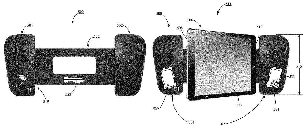
FIG. 35shows a front view of an alternate embodiment of an electronic game control apparatus500(also referred to herein as an input device500), constructed and operated in accordance with various embodiments disclosed and claimed herein. The input device500includes, but is not limited to, a first control module502, and a second control module504. The control modules (502,504) are adjacent to and confine a computing device506(ofFIG. 36) on at least two opposing sides508and510(each ofFIG. 36), of the plurality of sides of the computing device506. Collectively, and when joined together, by way of a structural bridge522, the input device500, and the computing device506, form an electronic gaming system511, as shown inFIG. 36.
In a preferred embodiment, the control module504, incorporates the eternal mechanisms and features of the control module404, ofFIGS. 26 and 28, including the tensioning mechanism446, but absent the sizing mechanism468. While the control module502, incorporates the eternal mechanisms and features of the control module402, ofFIGS. 26 and 27, but absent the adjustment feature428, and the sizing mechanism468. Accordingly, the input device500can accommodate computing devices of varying length and width by incorporating the tensioning mechanism446, into control module504, to accommodate a length513, of the computing device560, and configuring the control modules (502,504) to allow the sides (508,510) of the computing device506, to protrude, or extend beyond the confines of a length515, of the control modules (502,504), in a vertical direction along a width517, of the computing device506.
In a preferred embodiment, as shown byFIG. 35, the structural bridge522, secures the pair of control modules (502,504) one to the other. Preferably, the structural bridge522, is configured such that the structural bridge522, adaptively and snugly accommodate the length513, of the computing device506, as shown inFIG. 36.
In a preferred embodiment, as shown byFIG. 37, the control module504, includes at least, but is not limited to, a tensioning mechanism546, communicating with the structural bridge522. Preferably, the tensioning mechanism546, secures the structural bridge522, such that the structural bridge snugly accommodate the length513(ofFIG. 36), of the computing device506(ofFIG. 36).
In a preferred embodiment, as shown byFIG. 35, a communication link519, is provided by the input device500, which facilitating communication between the pair of control modules (502,504) and the computing device506(ofFIG. 36), and, as shown byFIG. 35, the structural bridge522, masks a mid-portion of the back of the computing device.
Continuing withFIG. 35, in a preferred embodiment, the communication link519, provides a communication module521, and in the alternative, provides a signal pathway523, for use in passing signals between the pair of control modules (502,504). In a preferred embodiment, the communication module521, is a wireless communication module521, which operates in a frequency range of 2.4 GHz. In an alternate preferred embodiment, the wireless communication module521, is a personal area network. As those skilled in the art, a personal area network (PAN) is a computer network used for communication among computerized devices, including telephones and personal digital assistants. PANs can be used for communication among the personal devices themselves (intrapersonal communication), or for connecting to a higher level network and the Internet (an uplink). A wireless personal area network (WPAN) is a PAN carried over wireless network technologies such as IrDA, Bluetooth, Wireless USB, Z-Wave, ZigBee, or even Body Area Network. The reach of a WPAN varies from a few centimeters to a few meters. A PAN may also be carried over wired computer buses such as USB and FireWire.
In an embodiment that utilizes the signal pathway523, as the communication link519, the signal pathway523, may be in the form of a metallic conductor, a fiber optic conductor, a conductive polymer, or the conductive layer of a flex circuit. The skilled artisan will further appreciate that the structural bridge522, may be either formed from a ridged material, such as a ridged polymer, or from a flexible material, such as a flexible polymer.
FIG. 38shows an exploded view in perspective of the control module504, of the input device500, ofFIG. 35. The control module504, includes at least but is not limited to, a tensioning mechanism546, communicating with the structural bridge522, by way of a fastening mechanism548(also referred to herein as an attachment stay548), of the tensioning mechanism546secured to the structural bridge522, as shown byFIG. 37.
The tensioning mechanism546, secures the structural bridge522, to a bottom cover550, of the control module504, such that the structural bridge522, cooperating with the tensioning mechanism546, snugly accommodates the length513(ofFIG. 36), of the computing device506(ofFIG. 36).
In a preferred embodiment, the bottom cover550, provides an attachment boss552, supporting a position guide554, and the tensioning mechanism546, includes at least, but not limited to, the attachment boss552, communicating with the structural bridge522, an attachment support556, cooperating with the attachment boss552. Preferably, the attachment support556, in cooperation with the attachment boss552, confines the structural bridge522vertically, but permits lateral movement of the structural bridge522, relative to the bottom cover550.
Preferably, the structural bridge522, is disposed between the bottom cover550, and a top cover558, which cooperates with the bottom cover450, to facilitate lateral movement of a portion of the structural bridge522. Preferably, a biasing structure560, communicating the attachment stay548(ofFIG. 37), provides variable tension between the structural bridge522, and the second control module504, thereby accommodating a predetermined amount of lateral movement of the structural bridge522, relative to the bottom cover550, as shown byFIG. 37.
As shown byFIG. 37, in a preferred embodiment, the attachment stay548, includes at least, but not limited to, a guide aperture562, which is preferably slotted, interacting with the position guide554, of the attachment boss552(ofFIG. 38). The interaction of the guide aperture562, with the position guide554, limits the extent of lateral alignment between the structural bridge522, and the control modules (502,504). As further shown byFIG. 38, in a preferred embodiment, the attachment support556, further supports a plurality of control switches564, interacting with a circuit structure566, which preferably is a flex circuit566, and the biasing structure560, is preferably a coiled spring460.
In a preferred embodiment, the structural bridge522, provides a width525, less than its length527, as shown byFIG. 37, and the back of the computing device506, extending above and below the width525, of the structural bridge522.
Returning toFIG. 36, in a preferred embodiment, the input device500, includes an auxiliary power source529, and an auxiliary data storage device531, which preferably includes a cache portion533. Preferably, the auxiliary power source529, is a lithium ion battery, which provides power to the input device500, and the computing device506, when the power source of the computing device506is depilated; and the auxiliary data storage device531is preferably a solid state hard drive.
FIG. 39shows a further embodiment of the electronic gaming system511, in which the input device500, provides a keyboard module535, and in which the keyboard module535, passes signals to the computing device506, the signals control images displayed on the display screen537, of the computing device506.
FIG. 40shows a still further embodiment of the electronic gaming system511, in which the input device500, provides the keyboard module535, and in which the keyboard module535, passes signals to the computing device506, the signals control images displayed on the display screen537, of the computing device506.FIG. 40further shows that the communication link519, via the communication module521, is further configured to communicate with a second display541wirelessly. That is the second display541, is remote from and mechanically disassociated from the electronic display screen537, of the computing device506.
Continuing withFIG. 40, preferably each control module (502,504) provides a directional control device543. In a preferred embodiment, each direction control device543, is configured to facilitate a first position adjacent the top cover558, of control module504, or a first position adjacent a top cover545, of control module502, and a second position, the second position displaced a predetermined vertical distance away from the first position. Further in the preferred embodiment, each directional control module543is a joystick.
FIG. 41discloses the electronic game control apparatus400(also referred to herein as an input device400), which in a preferred embodiment provides the first control module402, the second control module404, and the structural bridge422, which collectively secures the computing device418. In a preferred embodiment, a back of the structural bridge422, supports a touch sensitive control module544, which in a preferred embodiment is a touch screen544.
FIG. 42discloses the electronic game control apparatus400(also referred to herein as an input device400), which in a preferred embodiment provides the first control module402, the second control module404, and the structural bridge422, which collectively secures the computing device418. In a preferred embodiment, a back427, of the second control module, supports the touch sensitive control module544, which in a preferred embodiment is a touch screen544.
FIG. 43discloses the electronic game control apparatus500(also referred to herein as an input device500), which in a preferred embodiment provides the first control module502, the second control module504, and the structural bridge522. In a preferred embodiment, a back of the structural bridge522, supports a touch sensitive control module546, which in a preferred embodiment is a touch screen546.
FIG. 44discloses the electronic game control apparatus500(also referred to herein as an input device500), which in a preferred embodiment provides the first control module502, the second control module504, and the structural bridge522. In a preferred embodiment, a back side of the second control module504, supports the touch sensitive control module546, which in a preferred embodiment is a touch screen546.
It is to be understood that even though numerous characteristics and configurations of various embodiments of the present invention have been set forth in the foregoing description, together with details of the structure and function of various embodiments of the invention, this detailed description is illustrative only, and changes may be made in detail, especially in matters of structure and arrangements of parts within the principles of the present invention to the full extent indicated by the broad general meaning of the terms in which the appended claims are expressed. For example, the particular elements may vary depending on the particular computing device without departing from the spirit and scope of the present invention.
Claims
- A combination comprising: a computing device, the computing device providing an upper, lower, left and right side, collectively the sides of the computing device, and an electronic display screen, the electronic display screen having a corresponding side adjacent each of the sides of the computing device;a pair of confinement structures, the pair of confinement structures adjacent to and confining the computing device on at least two opposing sides, but not more than three sides of the sides of the computing device, and in which a first confinement structure of the pair of confinement structures provides a first communication link, while a second confinement structure of the pair of confinement structures provides a second communication link;a structural bridge disposed between the pair of confinement structures, the structural bridge comprising, a passageway between the pair of confinement structures, the passageway promotes communication between the first communication link and the computing device, the passageway further promotes communication between the second communication link and the computing device;fastening mechanisms, the fastening mechanisms secure the first confinement structure to a first side of the structural bridge, and further in which the fastening mechanisms secure the second confinement structure to a second side of the structural bridge;and an input device, the input device comprising a pair of control modules, each control module of the pair of control modules secured to a corresponding confinement structure of the pair of confinement structures, each control module in electronic communication with the communication link of its corresponding confinement structure, each of the pair of control modules providing input module apertures, each input module aperture secures an instructional input device, wherein said input module apertures are adjacent each of the at least two opposing sides of the sides of the computing device, and wherein the input device is a separate and distinct structure from either of the pair of confinement structures, forming no structural portion of either of the pair of confinement structures, and in which the confinement structures are separate and distinct structures from the structural bridge, forming no structural portion of the structural bridge.
- The combination of claim 1 , in which the structural bridge is a rigid structural bridge, the rigid structural bridge supports electronics associated with the computing device.
- The combination of claim 2 , in which the computing device further comprising a back, the back provides an internal surface, an external surface, and upper, lower, left and right sides, collectively the sides of the back of the computing device, the back of the computing device cooperating with the sides of the computing device.
- The combination of claim 3 , in which the rigid structural bridge cooperates with the back of the computing device.
- The combination of claim 4 , in which the rigid structural bridge cooperating with the back of the computing device is adjacent to the external surface of the back of the computing device.
- The combination of claim 4 , in which each instructional input device passes signals through its corresponding communication link to the computing device, the signals controlling images displayed on the electronic display screen of the computing device.
- The combination of claim 4 , in which the input device is a pair of game control modules, and in which each game control module passes signals through its corresponding communication link to the computing device, the signals controlling images displayed on the electronic display screen of the computing device.
- The combination of claim 2 , in which the electronics supported by the rigid structural bridge is a communication module associated with the computing device.
- The combination of claim 2 , in which the rigid structural bridge, the pair of confinement structures, and the fastening mechanism form a communication port.
- A combination comprising: a computing device, the computing device providing an upper, lower, left and right side, collectively the sides of the computing device, and an electronic display screen, the electronic display screen having a corresponding side adjacent each of the sides of the computing device;a pair of modules, the pair of modules adjacent to and confining the computing device on at least two opposing sides, but not more than three sides of the sides of the computing device, a module of the pair of modules providing a communication link;a structural bridge disposed between the pair of modules, the structural bridge includes, but is not limited to, a passageway between the pair of modules, and a fastening mechanism, the passageway promotes communication between the communication link and the computing device, while the fastening mechanism unifies the pair of modules with the structural bridge, and in which the structural bridge provides a void in the midsection of the structural bridge, the void having right, left, upper, and lower sides, each side communicating with a material of the structural bridge;and a pair of instructional input devices, each instructional input device of the pair of instructional input devices interacting with a corresponding module of the pair of modules, each instructional input device in electronic communication with the communication link, each of the pair of instructional input devices adjacent a corresponding side of the at least two opposing sides of the sides of the computing device.
- The combination of claim 10 , in which the structural bridge is a flexible structural bridge, the flexible structural bridge supports electronics associated with the computing device, and wherein the input device is a separate and distinct structure from the pair of modules, forming no structural portion of the pair of modules.
- The combination of claim 11 , in which the electronics supported by the flexible bridge is fiber optics.
- The combination of claim 12 , in which the computing device further comprising a back, the back provides an internal surface, an external surface, and upper, lower, left and right sides, collectively the sides of the back of the computing device, the back of the computing device cooperating with the sides of the computing device.
- The combination of claim 13 , in which the flexible structural bridge cooperates with the external surface of the back.
- The combination of claim 14 , in which each instructional input device of the pair of instructional input devices passes signals through the communication link to the computing device, the signals controlling images displayed on the electronic display screen of the computing device.
- A combination comprising: a pair of confinement structures;a first communication link, the first communication link confined by a first confinement structure of the pair of confinement structures;a second communication link, the second communication link confined by a second confinement structure of the pair of confinement structures;a structural bridge disposed between the first confinement structure and the second confinement structure, the structural bridge comprising an electronics communications passageway between the first and second confinement structures;fastening mechanisms, the fastening mechanisms secure each the first confinement structure and the second confinement structure of the pair of confinement structures to the structural bridge;and a pair of control modules, a first control module of the pair of control modules attached to the first confinement structure, and a second control module of the pair of control modules attached to the second confinement structure, the first control module in electronic communication with the first communication link, the second control module in electronic communication with the second communication link, each the first and the second control modules comprising a plurality of input module apertures, each input module aperture secures an instructional input device, and in which neither the first nor the second control module from a structural portion of either the first or second confinement structures.
- The combination of claim 16 , further comprising a computing device, the computing device comprising an upper, lower, left and right side, collectively the sides of the computing device, the computing device disposed between and in contact adjacency with each the first and second confinement structure of the pair of confinement structures, the pair of confinement structures engaging the computing device on at least two opposing sides, but not more than three sides of the sides of the computing device, said pair of confinement structures are separate and distinct structures from the computing device.
- The combination of claim 17 , in which the structural bridge is a rigid structural bridge, the rigid structural bridge supports electronics associated with the computing device.
- The combination of claim 18 , in which the computing device further comprising a back, the back provides an internal surface, an external surface, and upper, lower, left and right sides, collectively the sides of the back of the computing device, the back of the computing device cooperating with the sides of the computing device, and in which the rigid structural bridge cooperates with the back of the computing device.
- The combination of claim 19 , in which the rigid structural bridge, the pair of confinement structures, and the fastening mechanism form a communication port.
Disclaimer: Data collected from the USPTO and may be malformed, incomplete, and/or otherwise inaccurate.