U.S. Pat. No. 9,764,230
GAME CONTROLLER WITH USER-REPLACEABLE THUMBSTICK TOP
AssigneeMicrosoft Technology Licensing, LLC
Issue DateJune 9, 2015
Illustrative Figure
Abstract
A user input device is described that includes a thumbstick that comprises a thumbstick module and a thumbstick cap that is connected thereto. The thumbstick cap includes a thumbstick base that is mounted upon the thumbstick module and a thumbstick top that can be removably connected to the thumbstick base. The manner of interconnection between the thumbstick top and the thumbstick base is such that a user can connect and disconnect the two components without having to disassemble the game controller and without having to use any tools.
Description
The features and advantages of the embodiments described herein will become more apparent from the detailed description set forth below when taken in conjunction with the drawings, in which like reference characters identify corresponding elements throughout. In the drawings, like reference numbers generally indicate identical, functionally similar, and/or structurally similar elements. The drawing in which an element is first identified is indicated by the leftmost digit(s) in the corresponding reference number. DETAILED DESCRIPTION I. Introduction The following detailed description discloses numerous example embodiments. The scope of the present patent application is not limited to the disclosed embodiments, but also encompasses combinations of the disclosed embodiments, as well as modifications to the disclosed embodiments. References in the specification to “one embodiment,” “an embodiment,” “an example embodiment,” or the like, indicate that the embodiment described may include a particular feature, structure, or characteristic, but every embodiment may not necessarily include the particular feature, structure, or characteristic. Moreover, such phrases are not necessarily referring to the same embodiment. Furthermore, when a particular feature, structure, or characteristic is described in connection with an embodiment, it is submitted that it is within the knowledge of persons skilled in the relevant art(s) to implement such feature, structure, or characteristic in connection with other embodiments whether or not explicitly described. A game controller is a type of input device that is designed to facilitate user interaction with a video game or other application executing on a computer, video game console, or other platform. For example, a game controller may provide a means by which a user can control a character or object within a video game. A variety of different types of game controllers exist and each game controller type may include one or more user-actuatable control elements via which a user can provide input. For example, ...
The features and advantages of the embodiments described herein will become more apparent from the detailed description set forth below when taken in conjunction with the drawings, in which like reference characters identify corresponding elements throughout. In the drawings, like reference numbers generally indicate identical, functionally similar, and/or structurally similar elements. The drawing in which an element is first identified is indicated by the leftmost digit(s) in the corresponding reference number.
DETAILED DESCRIPTION
I. Introduction
The following detailed description discloses numerous example embodiments. The scope of the present patent application is not limited to the disclosed embodiments, but also encompasses combinations of the disclosed embodiments, as well as modifications to the disclosed embodiments.
References in the specification to “one embodiment,” “an embodiment,” “an example embodiment,” or the like, indicate that the embodiment described may include a particular feature, structure, or characteristic, but every embodiment may not necessarily include the particular feature, structure, or characteristic. Moreover, such phrases are not necessarily referring to the same embodiment. Furthermore, when a particular feature, structure, or characteristic is described in connection with an embodiment, it is submitted that it is within the knowledge of persons skilled in the relevant art(s) to implement such feature, structure, or characteristic in connection with other embodiments whether or not explicitly described.
A game controller is a type of input device that is designed to facilitate user interaction with a video game or other application executing on a computer, video game console, or other platform. For example, a game controller may provide a means by which a user can control a character or object within a video game. A variety of different types of game controllers exist and each game controller type may include one or more user-actuatable control elements via which a user can provide input. For example, a conventional game controller that is designed to be held in two hands (sometimes referred to as a “gamepad,” “control pad,” or “joypad”) may include one or more user-actuatable buttons, triggers, thumbsticks, directional pads, touch pads, and the like. Each of these control elements may be manipulated by a user to generate various control signals for interacting with a video game.
As noted above, some game controllers include at least one thumbstick. A thumbstick (which may also be referred to as an “analog thumbstick,” “analog stick,” “joystick,” “control stick,” or simply a “stick”) is a game controller component that can be manipulated by a user to generate two-dimensional input for controlling or otherwise interacting with a video game or other application.
By way of example,FIG. 1shows a cross-sectional view of a portion of a conventional game controller100that includes a thumbstick102. Thumbstick102comprises a thumbstick module104and a thumbstick cap106that is attached thereto. Thumbstick module104is an electronic component that is mounted on a printed circuit board (not shown inFIG. 1) that is disposed within a housing of game controller100. Thumbstick module104includes a moveable post108and a plurality of sensors in the form of potentiometers. The potentiometers utilize continuous electrical activity to generate an analog input control signal based on a position of moveable post108in relation to a default “center” position.
Thumbstick cap106comprises a generally disk-shaped top110that is connected to a dome-shaped base114via a cylindrical stem112. Top110includes a first surface116and an opposing second surface118. First surface116is adapted to be manipulated by a user's finger (e.g., a user's thumb) and in this example is concave in shape. Thumbstick cap106also includes a connector120that extends perpendicularly from second surface118into a space defined by stem112and base114. Connector120defines a cavity into which post108is inserted, thereby mounting thumbstick cap106on thumbstick module104. By manipulating top110of thumbstick cap106, a user can cause post108to deviate from its default “center” position, thereby generating a two-dimensional analog input control signal. Post108is biased such that when there is no force being applied, post108will revert the default “center” position.
As further shown inFIG. 1, the housing of game controller100includes a top case122. Top case122includes a generally conical or volcano-shaped portion that surrounds an aperture124. Top110and stem112of thumbstick cap106extend outside of the housing of game controller100via aperture124, and are thus accessible for user manipulation. A portion of base114of thumbstick cap106is also externally exposed via aperture124. An edge126of top case122that surrounds aperture124limits the degree to which a user can displace thumbstick cap106in any given direction since, at a certain degree of displacement, stem112of thumbstick cap106will collide with edge126. Dome-shaped base114of thumbstick cap106is sized such that, no matter what the degree or direction of displacement of thumbstick cap106, the interior of the housing of game controller100will not be exposed via aperture124.
One issue with conventional game controller100is that the shape of thumbstick cap106may not be preferred by some users. For example, a user may prefer a thumbstick cap that has a stem that is longer than stem112, so that the thumbstick cap is taller (i.e., extends further away from top case122). As another example, a user may prefer a thumbstick cap that has a top with a convex or dome-shaped surface for finger interaction as opposed to concave-shaped first surface116. Any of a wide variety of other thumbstick cap shapes may be preferred by different users for different reasons. Furthermore, a single user may prefer different types of thumbstick cap shapes for different types of video games.
With the conventional implementation shown inFIG. 1, the user is essentially stuck with thumbstick cap106. If the user wants a thumbstick cap with a different shape, the user has very limited options. If other game controllers exist that are compatible with the user's video gaming platform and have thumbstick caps with the desired shape, then the user can choose to buy a new game controller entirely. This is a very expensive proposition for the user. Moreover, such other game controllers may not exist. It is also possible that some third parties may manufacture and/or sell replacement thumbstick caps for game controller100that have different shapes than thumbstick cap106. Such replacement caps can either be installed by the third party or provided to the user as part of a do-it-yourself kit. In either case, the installation of the replacement thumbstick cap will involve disassembling and reassembling game controller100using one or more tools, since the housing of game controller100must be opened up to carry out the installation. Such disassembly and reassembly may be difficult, time-consuming, and result in damage to game controller100if not carried out properly.
A related issue associated with conventional game controller100arises when thumbstick cap106is worn or broken and thus needs replacing. Again, the user's options are very limited. The user can buy a new game controller entirely, which is expensive. Alternatively, the user can install or have installed a replacement thumbstick cap, wherein such replacement will necessarily involve disassembling and reassembling game controller100. As noted above, such disassembly and reassembly may be difficult, time-consuming, and result in damage to game controller100if not carried out properly.
Embodiments described herein help address one or more of the foregoing issues. For example, embodiments described herein provide a thumbstick for a user input device, such as a game controller, that includes a thumbstick module and a thumbstick cap that is connected thereto. The thumbstick cap includes a thumbstick base that is mounted upon the thumbstick module and a thumbstick top that can be removably connected to the thumbstick base. The manner of interconnection between the thumbstick top and the thumbstick base is such that a user can connect and disconnect the two components without having to disassemble the game controller and without having to use any tools.
In an embodiment, a plurality of differently-shaped thumbstick tops may be provided, each of which can engage with the thumbstick base in a substantially similar manner. Such an embodiment enables a user to easily customize the thumbstick cap to achieve a desired shape. Thus, for example, a user may select a thumbstick top from among a plurality of thumbstick tops having stems of varying lengths in order to achieve a desired thumbstick height. As another example, a user may select a thumbstick top from among a plurality of thumbstick tops having differently-shaped surfaces for finger interaction (e.g., concave, convex or flat). A wide variety of differently-shaped thumbstick tops may be provided to facilitate a high level of user customization. Such customization can be achieved by the user at any time after the user has purchased the game controller. Since the thumbstick tops can be connected to and disconnected from the thumbstick base without the use of tools, the user can carry out such customization quickly and easily.
In accordance with the foregoing embodiment, the user can improve his or her gaming experience by modifying the thumbstick cap to obtain a preferred shape thereof. The user's preference in this regard may be a general preference or a preference that is based on a particular video game that the user intends to play. In further accordance with the foregoing embodiment, different users of the same game controller may modify the thumbstick cap thereof to suit their own personal shape preferences prior to use.
In a further embodiment, a plurality of thumbstick tops having different aesthetic appearances may be provided, each of which can engage with the thumbstick base in a substantially similar manner. Such an embodiment enables a user to easily customize the thumbstick cap to achieve a desired aesthetic appearance. Thus, for example, a user may select a thumbstick top of a particular color from among a plurality of different-colored thumbstick tops. As another example, a user may select a thumbstick top that has a desired logo, image, text, or other design formed thereon. A logo, image, text or other design may be formed on a thumbstick top via molding, printing, etching, engraving, stamping, or other suitable technique. A wide variety of thumbstick tops having different appearances may be provided to facilitate a high level of user customization.
Still further customization beyond shape and aesthetic appearance may be achieved by utilizing the user-replaceable thumbstick tops described herein. For example, a user may select from among thumbstick tops that are made of different materials (e.g., different plastics and/or metals) and from among thumbstick tops that have different surfaces (e.g., smooth or rough).
An additional advantage associated with the use of the aforementioned user-replaceable thumbstick tops is that a user can replace a worn or broken thumbstick top with a new one without having to replace a game controller and without having to take the game controller apart and put it back together again.
In the following sections, various embodiments of a user input device that includes a user-replaceable thumbstick top will be more fully described. In particular, Section II describes various example game controllers and user-replaceable thumbstick tops that may be connected thereto. Section III describes some additional exemplary embodiments. Section IV provides some concluding remarks.
II. Example Game Controllers and User-Replaceable Thumbstick Tops that May be Connected Thereto
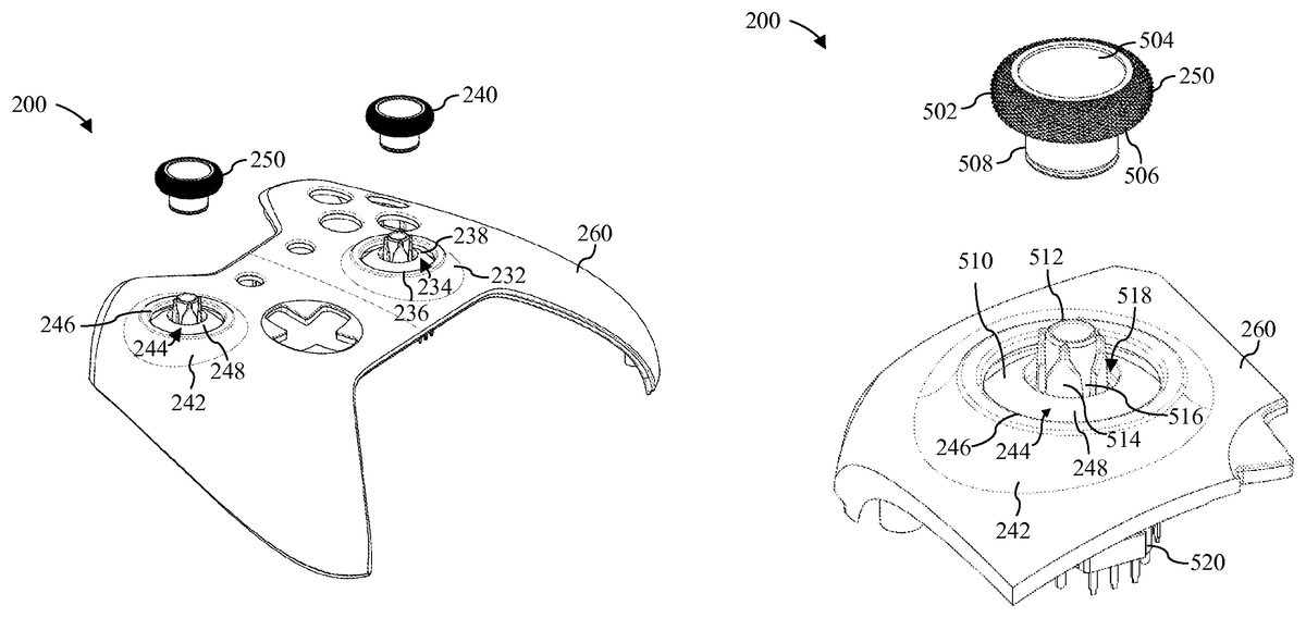
FIG. 2shows a perspective view of an example game controller200in accordance with an embodiment that includes two thumbsticks, each of which comprises a user-replaceable thumbstick top.FIG. 3shows a top view of game controller200. As shown in these figures, game controller200comprise a housing202that includes a number of mechanically interconnected components, including a top case260, a bottom case264and a bottom trim component262, that together define a cavity in which various internal components of game controller200are disposed. In an embodiment, each of the aforementioned components of housing202is formed from a thermoplastic material, such as PC/ABS (a compounded blend of polycarbonate (PC) and acrylonitrile butadiene styrene (ABS)). However, this example is not intended to be limiting, and the components of housing202may be formed from other materials as well.
Housing202includes a plurality of apertures via which various user-actuatable control elements of game controller200are exposed to and rendered manipulable by a user. The user-actuatable control elements of game controller200include a right thumbstick cap204, a left thumbstick cap206, a directional pad (D-pad)208, a plurality of face buttons210,212,214,216,218,220and222, a left bumper button224, a right bumper button226, a left trigger302, and a right trigger304. Generally speaking, each of these user-actuatable control elements is connected to one or more sensors disposed within game controller200. Such sensor(s) operate to detect when a user has interacted with a particular user-actuatable control element. Electronic circuitry disposed within game controller200operates to convert data generated by such sensors into user input control signals that may then be transmitted via a wired or wireless communication medium to a computer, game console, or other platform, where such user input control signals may be used to control a video game or other application. In embodiments, some or all of the aforementioned sensors and electronic circuitry are disposed on a printed circuit board that is disposed internal to housing202.
Right thumbstick cap204extends from top case260via an aperture234defined therein. Aperture234is surrounded by an edge236and a generally conical or volcano-shaped portion232of top case260. During user manipulation of right thumbstick cap204, edge236limits the degree to which a user can displace right thumbstick cap204in any direction since, at a certain degree of displacement, a stem of right thumbstick cap204will collide with edge236.
Right thumbstick cap204comprises a thumbstick base238and a thumbstick top240. InFIGS. 2 and 3, thumbstick top240is removably connected to thumbstick base238. In this connected state, a user may interact with thumbstick top240(e.g., by using his finger to manipulate thumbstick top240) to cause displacement of right thumbstick cap204. As will be described herein, thumbstick base238and thumbstick top240are designed in such a manner that a user of game controller200can disconnect thumbstick top240from thumbstick base238without having to disassemble game controller200and without having to use any tools.
Left thumbstick cap206extends from top case260via an aperture244defined therein. Aperture244is surrounded by an edge246and a generally conical or volcano-shaped portion242of top case260. During user manipulation of left thumbstick cap206, edge246limits the degree to which a user can displace left thumbstick cap206in any direction since, at a certain degree of displacement, a stem of left thumbstick cap206will collide with edge246.
Left thumbstick cap206comprises a thumbstick base248and a thumbstick top250. InFIGS. 2 and 3, thumbstick top250is removably connected to thumbstick base248. In this connected state, a user may interact with thumbstick top250(e.g., by using his finger to manipulate thumbstick top250) to cause displacement of left thumbstick cap206. As will be described herein, thumbstick base248and thumbstick top250are designed in such a manner that a user of game controller200can disconnect thumbstick top250from thumbstick base248without having to disassemble game controller200and without having to use any tools.
FIG. 4shows a perspective view of a portion of game controller200that includes top case260, right thumbstick cap204(which is comprised of thumbstick base238and thumbstick top240) and left thumbstick cap206(which is comprised of thumbstick base248and thumbstick top250). As shown inFIG. 4, thumbstick top240of right thumbstick cap204is disconnected from thumbstick base238of right thumbstick cap204. A portion of thumbstick base238to which thumbstick top240may be removably connected is externally accessible with respect to housing202through aperture234. In this disconnected state, a user of game controller200can replace thumbstick top240with another thumbstick top that uses an interconnect mechanism that is substantially similar to that used to connect thumbstick top240to thumbstick base238. In this disconnected state, a user of game controller200can also reconnect thumbstick top240to thumbstick base238.
As further shown inFIG. 4, thumbstick top250of left thumbstick cap206is disconnected from thumbstick base248of left thumbstick cap206. A portion of thumbstick base248to which thumbstick top250may be removably connected is externally accessible with respect to housing202through aperture244. In this disconnected state, a user of game controller200can replace thumbstick top250with another thumbstick top that uses an interconnect mechanism that is substantially similar to that used to connect thumbstick top250to thumbstick base248. In this disconnected state, a user of game controller200can also reconnect thumbstick top250to thumbstick base248.
FIG. 5shows a perspective view of a portion of game controller200that includes a portion of top case260, left thumbstick cap206(which is comprised of thumbstick base248and thumbstick top250), and a left thumbstick module520to which thumbstick base248is connected. As was the case withFIG. 4, thumbstick top250of left thumbstick cap206is disconnected from thumbstick base248of left thumbstick cap206. Additional details concerning thumbstick base248and thumbstick top250will now be provided in reference toFIG. 5.
As shown inFIG. 5, thumbstick base248comprises a dome-shaped component510that includes a cylindrical post512that extends perpendicularly from a top surface thereof. A circular depression518is formed in the top surface of dome-shaped component510and surrounds cylindrical post512. Cylindrical post512is also surrounded by four protrusions that extend therefrom and that define four tapered channels around an exterior wall thereof. A representative protrusion514and a representative tapered channel516are indicated inFIG. 5.
As further shown inFIG. 5, thumbstick top250comprises a head502and a cylindrical stem508that is connected thereto. Head502includes a first surface504and an opposing second surface506. First surface504is adapted to be manipulated by a user's finger (e.g., a user's thumb) and in this example is concave in shape. Stem508extends perpendicularly from second surface506.
FIG. 6shows a perspective view of thumbstick top250that reveals additional features thereof. As shown inFIG. 6, stem508defines a generally cylindrical cavity602that is open on one end—namely, the end that is opposite to second surface506of head502. An inner wall604of stem508surrounds cavity602. Four wedge-shaped protrusions are formed on inner wall604. A representative wedge-shaped protrusion606is indicated inFIG. 6.
Cylindrical post512of thumbstick base248is sized and shaped such that cylindrical cavity602of thumbstick top250will fit closely thereon. The four tapered channels that surround post512are situated such that they may be aligned with the four wedge-shaped protrusions that extend from inner wall604of thumbstick top250, respectively, and are sized and shaped to receive such wedge-shaped protrusions.
To achieve a connection between thumbstick top250and thumbstick base248, a user can position thumbstick top250over post512of thumbstick base248in a manner similar to that shown inFIG. 5. The four wedge-shaped protrusions that are formed on inner wall604of thumbstick top250must be brought into alignment with the four tapered channels that surround post512of thumbstick base248, respectively. A downward force can then be applied to thumbstick top250, which will cause each wedge-shaped protrusion to be inserted into a corresponding tapered channel. Due to the geometry of the wedge-shaped protrusions and the tapered channels, the insertion of each wedge-shaped protrusion into a corresponding tapered channel will result in the generation of a wedging or squeezing force that is generally perpendicular to the inclined surfaces of the wedge-shaped protrusion and that will help hold thumbstick top250onto post512of thumbstick base248. The insertion of each wedge-shaped protrusion into a corresponding tapered channel will also prevent thumbstick top250from tilting or rotating when thumbstick top250is engaged with thumbstick base248and is being manipulated by a user.
To form the aforementioned connection, a user may applying a downward force to thumbstick top250by manually applying pressure thereto (e.g., by pushing a finger downward onto first surface504of head502). However, as will be discussed below, in example game controller200, thumbstick top250comprises a ferromagnetic material that is attracted to magnets and thumbstick base248includes a magnet. In accordance with this implementation, when thumbstick top250is generally positioned in the manner shown inFIG. 5and is brought sufficiently close to thumbstick base248, the magnet in thumbstick base248will generate an attractive force that will help thumbstick top250automatically align itself with and snap itself onto post512of thumbstick base248. Thus, the use of such a magnet in thumbstick base248in combination with the use of a ferromagnetic material that is attracted to the magnet in thumbstick top250helps make the connection process easier for the user. Furthermore, this magnet-based connection technique increases the strength of the connection between thumbstick base248and thumbstick top250. Additionally, this magnet-based connection technique may produce a distinct snapping or clicking sound that provides confirmation to the user that a secure connection has been made.
These and other features of game controller200will now be further described in reference toFIG. 7andFIG. 8. In particular,FIG. 7shows an exploded view of left thumbstick module520and left thumbstick cap206(which comprises thumbstick base248and thumbstick top250) of game controller200.FIG. 8shows an exploded cross-sectional view of left thumbstick module520, left thumbstick cap206, and a portion of top case260of game controller200.
Left thumbstick module520is an electronic component that is mounted on a printed circuit board (not shown) that is disposed within housing202of game controller200. Left thumbstick module520includes a moveable post710and a plurality of sensors in the form of potentiometers. The potentiometers utilize continuous electrical activity to generate an analog input control signal based on a position of moveable post710in relation to a default “center” position. Post710is biased such that when there is no force being applied, post710will revert to the default “center” position.
Thumbstick base248is configured to be mounted upon moveable post710of left thumbstick module520. Thumbstick base248comprises dome-shaped component510, an adhesive component702, a ring magnet704, a metal shield706, and polyimide tape708.
Dome-shaped component510was previously described in reference toFIG. 5. In an embodiment, dome-shaped component510is formed from a material that exhibits relatively weak attraction to magnets. For example, in one embodiment, dome-shaped component510is formed from 316 stainless steel. Such a material may be used to minimize interference with any magnetic interaction between ring magnet704and the ferromagnetic material in thumbstick top250. Still other materials may be used to form dome-shaped component510, including other metals or non-metals.
As shown inFIG. 8, a bottom surface of dome-shaped component510defines a ring-shaped recess802that is sized to closely accommodate ring magnet704. Prior to insertion of ring magnet into recess802, adhesive component702is inserted there between. Adhesive component702operates to keep ring magnet704securely fixed in recess802. In one embodiment, adhesive component702comprises double-coated pressure sensitive tape. As will be appreciated by persons skilled in the relevant art(s), double-coated pressure sensitive tape comprises a substrate that is coated on both sides with a pressure sensitive adhesive. However, this is only an example, and other adhesive components may be used to secure ring magnet704into recess802.
In an embodiment, ring magnet704comprises a neodymium rare earth magnet, although this is only an example and other suitable types of magnets may be used. In a further embodiment, ring magnet704is magnetized axially. In a still further embodiment, ring magnet704comprises a quad pole ring magnet. A quad pole ring magnet will have a magnetic field that is smaller than a dipole ring magnet (assuming all other characteristics of the magnet are substantially similar) and may be used to reduce or avoid interference between the magnetic field generated by ring magnet704and one or more sensors disposed within game controller200.
As can be seen inFIG. 8, cylindrical post512extends both above the top surface of dome-shaped component510and below the bottom surface thereof. Ring magnet704is fitted around post512beneath the bottom surface of dome-shaped component510. Below ring magnet704, a steel shield706is also fitted around post512and is held in place by a magnetic attraction to ring magnet704. Steel shield706operates to help block the magnetic field generated by ring magnet704so as to reduce or avoid interference between the magnetic field generated by ring magnet704and one or more sensors disposed within game controller200. A layer of polyimide tape706(e.g., KAPTON® tape) is fastened to a bottom surface of steel shield706and operates to protect electronic components internal to game controller200from electrostatic discharge (ESD).
Post512of dome-shaped component510defines a cavity804into which moveable post710of thumbstick module520is inserted. Cavity804may be sized and shaped such that an interference fit is achieved between dome-shaped component510and moveable post710. Alternatively or additionally, glue or some other adhesive may be used to secure dome-shaped component510to moveable post710. Moveable post710is inserted into cavity804through circular gaps in each of polyimide tape708, metal shield706, ring magnet704and adhesive component702.
As can also be seen in the cross-sectional view ofFIG. 8, thumbstick top250includes a component806that is made of a ferromagnetic material and comprises stem508and a portion of head502. In an embodiment, component806is formed from 17-4 PH stainless steel, which exhibits relatively strong attraction to magnets. However, this is only an example, and other types of materials may be used to implement component806. Of course, to facilitate a magnetic connection to thumbstick base248, the material selected for component806will preferably be a material that exhibits at least some attraction to magnets.
As further shown inFIG. 8, thumbstick top250also comprises a cover808that is connected to component806and forms the external surface of head502. In an embodiment, cover808comprises a thermoplastic elastomer (TPE) that is overmolded onto component806. However, a variety of other materials may be used to form cover808, including plastic or rubber. Furthermore, in alternate embodiments, the entirety of thumbstick top250may be formed from the same material, such as a ferromagnetic material that exhibits a suitable level of magnetic attraction to ring magnet704.
FIG. 9shows a cross-sectional view of left thumbstick module520, left thumbstick cap206(which comprises thumbstick base248and thumbstick top250), and a portion of top case260of game controller200. InFIG. 9, thumbstick top250is disconnected from thumbstick base248.FIG. 10shows a cross-sectional view of the same components shown inFIG. 9, except that inFIG. 10thumbstick top250is connected to thumbstick base248. As can be seen inFIGS. 9 and 10, circular depression518of thumbstick base248into which stem508of thumbstick top250is inserted is closely positioned to and vertically aligned with recess802and ring magnet704. This design helps to bring stem508into close proximity to ring magnet704and increase the magnetic attraction therebetween.
When thumbstick top250is connected to thumbstick base248in the manner shown inFIG. 10, the interaction between the wedge-shaped protrusions formed on inner wall604of thumbstick top250and the tapered channels formed on post512of thumbstick base248as well as the magnetic attraction between component806of thumbstick top250and ring magnet704of thumbstick base248help to create a relatively strong and secure connection between thumbstick top250and thumbstick base248. In such a connected state, a user of game controller200can manipulate thumbstick top250of left thumbstick cap206, wherein such manipulation will cause a displacement of moveable post710of left thumbstick module520from the default “center” position and result in the generation of an analog input control signal. During the user's manipulation of thumbstick top250, the connection formed between thumbstick top250and thumbstick base248will help thumbstick top250remain securely seated on post512of thumbstick base248and will help prevent thumbstick top250from wobbling or rotating.
To remove thumbstick top250from thumbstick base248, a user can pull upward on thumbstick top250. The degree of force required to remove thumbstick top250from thumbstick base248may vary depending on the particulars of the design and on how much downward force was applied to thumbstick top250when connecting it to thumbstick base248. In embodiments, such removal of thumbstick top250from thumbstick base248can be achieved manually (e.g., by pinching or grabbing head502of thumbstick top250using two or more fingers and pulling upward) without the use of any tools.
As shown inFIG. 10, dome-shaped component510of thumbstick base248has a diameter that is greater than the diameter of aperture244. This helps ensure that thumbstick base248will remain seated securely in game controller200even when a user is pulling upward on thumbstick top250. As was previously mentioned, dome-shaped component510may also have an interference fit with moveable post710of thumbstick module520and/or be affixed thereto using glue or other adhesive.
It is to be understood that the foregoing description with respect to left thumbstick module520and left thumbstick cap206is equally applicable to a right thumbstick module (not shown) and right thumbstick cap204of game controller200. Thus, in an embodiment, the interconnection between thumbstick top240and thumbstick base238of right thumbstick cap204is implemented in a substantially similar manner to that described above for thumbstick top250and thumbstick base248of left thumbstick cap206.
Only one type of thumbstick top (a thumbstick top having the features of thumbstick top240or thumbstick top250) was described in the foregoing description of game controller200. However, in an embodiment, one or more differently-shaped thumbstick tops are provided, each of which can engage with thumbstick base238or thumbstick base248in a substantially similar manner to that described above. In accordance with such an embodiment, each differently-shaped thumbstick top comprises a stem comprising a ferromagnetic material and having an inner wall with wedge-shaped protuberances that is configured to be mounted on post512of thumbstick base248(or a like post of thumbstick base238). Such an embodiment enables a user of game controller200to easily customize the thumbstick caps thereof to achieve a desired shape. Thus, for example, a user may select a thumbstick top from among a plurality of thumbstick tops having stems of varying lengths in order to achieve a desired thumbstick height. As another example, a user may select a thumbstick top from among a plurality of thumbstick tops having differently-shaped surfaces for finger interaction (e.g., concave, convex or flat). A wide variety of differently-shaped thumbstick tops may be provided to facilitate a high level of user customization. Such customization can be achieved by the user at any time after the user has purchased game controller200. Since the thumbstick tops can be connected to and disconnected from thumbstick base238or thumbstick base248without the use of tools, the user can carry out such customization quickly and easily.
In accordance with the foregoing embodiment, the user can improve his or her gaming experience by modifying one or both thumbstick caps of game controller200to obtain a preferred shape thereof. The user's preference in this regard may be a general preference or a preference that is based on a particular video game that the user intends to play. In further accordance with the foregoing embodiment, different users of the game controller200may modify one or both thumbstick caps thereof to suit their own personal shape preferences prior to use.
In a further embodiment, a plurality of thumbstick tops having different aesthetic appearances are provided, each of which can engage with thumbstick base238or thumbstick base248in a substantially similar manner to that described above. Such an embodiment enables a user to easily customize the thumbstick cap to achieve a desired aesthetic appearance. Thus, for example, a user may select a thumbstick top of a particular color from among a plurality of different-colored thumbstick tops. As another example, a user may select a thumbstick top that has a desired logo, image, text, or other design formed thereon. A logo, image, text or other design may be formed on a thumbstick top via molding, printing, etching, engraving, stamping, or other suitable technique. A wide variety of thumbstick tops having different appearances may be provided to facilitate a high level of user customization.
Still further customization beyond shape and aesthetic appearance may be achieved by utilizing the user-replaceable thumbstick tops described herein. For example, a user may select from among thumbstick tops that are made of different materials (e.g., different plastics and/or metals) and from among thumbstick tops that have different surfaces (e.g., smooth or rough).
An additional advantage associated with the use of the aforementioned user-replaceable thumbstick tops is that a user can replace a worn or broken thumbstick top with a new one without having to replace game controller200and without having to take game controller200apart and put it back together again.
The foregoing description of game controller200provides only one example of a manner in which a thumbstick cap may be removably connected to a thumbstick base. Such example is not intended to be limiting. In fact, a variety of alternate mechanisms may be used to implement such a connection. To illustrate this, a number of different connection mechanisms will now be described with respect toFIGS. 11-34. Each of these connection mechanisms may be used to implement a different embodiment of a game controller having replaceable thumbstick tops. Each such embodiment can provide similar benefits to those described above with respect to game controller200.
For example,FIGS. 11-15show a thumbstick1100in which a pair of magnets is used to removably connect a thumbstick top1102to a thumbstick base1104.
FIG. 11shows a perspective view of thumbstick1100in which thumbstick top1102is disconnected from thumbstick base1104. As shown inFIG. 11, thumbstick base1104, which is mounted upon a thumbstick module1106, comprises a dome-shaped component1110that includes a cylindrical post1112that extends perpendicularly from a top surface thereof. A circular depression1114is formed in the top surface of dome-shaped component1110and surrounds cylindrical post1112. A first magnet1116is disposed in a recess formed at a top of post1112. First magnet1116may be fixed in the recess using a pressure sensitive adhesive (e.g., double-coated pressure sensitive tape), glue, or some other adhesive. In an alternate embodiment, first magnet1116may be fully embedded within post1112to ensure that it cannot be removed from or fall out of dome-shaped component1110.
As further shown inFIG. 11, thumbstick top1102comprises a head1122and a cylindrical stem1120that is connected thereto. Head1122includes a first surface1126and an opposing second surface1128. First surface1126is adapted to be manipulated by a user's finger (e.g., a user's thumb) and in this example is concave in shape. Stem1120extends perpendicularly from second surface1128. Stem1120defines a generally cylindrical cavity1130that is open on one end—namely, the end that is opposite to second surface1128of head1122. Four semicircular projections extend from the open end of stem1120and define four channels in stem1120. A representative semicircular projection1132and a representative channel1134are indicated inFIG. 11.
FIG. 12shows a perspective view of dome-shaped component1110that illustrates additional features thereof. As shown inFIG. 12, four wedge-shaped protrusions extend from an outer wall of circular depression1114to cylindrical post1112, thereby defining four semicircular channels around post1112. A representative wedge-shaped protrusion1202and a representative semicircular channel1204have been indicated inFIG. 12.
Cylindrical post1112of thumbstick base1104is sized and shaped such that cylindrical cavity1130of thumbstick top1102will fit closely thereon. The four semicircular channels that surround post1112are situated such that they can be aligned with the four semicircular projections that extend from the open end of stem1120, respectively, and are sized and shaped to receive such semicircular projections. Likewise, the four channels that are defined by stem1120are situated such that they can be aligned with the four wedge-shaped protrusions that surround post1112, respectively, and are sized and shaped to receive such wedge-shaped protrusions.
To achieve a connection between thumbstick top1102and thumbstick base1104, a user can place thumbstick top1102over post1112of thumbstick base1104in a manner similar to that shown inFIG. 11. The four semicircular projections that extend from the open end of stem1120of thumbstick top1102must be brought into alignment with the four semicircular channels that surround post1112of thumbstick base1104, respectively. A downward force can then be applied to thumbstick top1102, which will cause each semicircular projection to be inserted into a corresponding semicircular channel. This will also cause each of the wedge-shaped protrusions of thumbstick base1104to be lodged in a corresponding channel of thumbstick top1102. This configuration will prevent thumbstick top1102from tilting or rotating when thumbstick top1102is engaged with thumbstick base1104and is being manipulated by a user. In an alternate embodiment, the channels formed in thumbstick top1102may be tapered so as to create greater interference with the wedge-shaped protrusions of thumbstick base1104.
To form the aforementioned connection, a user may apply a downward force to thumbstick top1102by manually applying pressure thereto (e.g., by pushing a finger downward onto first surface1126of head1122). However, as will be discussed below, thumbstick top1102comprises a second magnet1304(shown inFIG. 13) that is attracted to first magnet1116in thumbstick base1104. Thus, when thumbstick top1102is generally positioned in the manner shown inFIG. 11and is brought sufficiently close to thumbstick base1104, the attraction between first magnet1116in thumbstick base and second magnet1304in thumbstick top1102will help thumbstick top1102automatically align itself with and snap itself onto post1112of thumbstick base1104. Thus, the use of first magnet1116in thumbstick base1104in combination with the use of second magnet1304in thumbstick top1102helps make the connection process easier for the user. Furthermore, this dual magnet connection technique increases the strength of the connection between thumbstick top1102and thumbstick base1104. Additionally, this magnet-based connection technique may produce a distinct snapping or clicking sound that provides confirmation to the user that a secure connection has been made.
FIG. 13shows an exploded view of thumbstick1100.FIG. 13shows that thumbstick module1106includes a moveable post1302upon which dome-shaped component1110is mounted. Thumbstick module1106and moveable post1302operate in a substantially similar manner to thumbstick module520and moveable post710as described above in reference to game controller200.FIG. 13also shows second magnet1304that is disposed within thumbstick top1102.
FIG. 14shows a cross-sectional view of thumbstick1100in which thumbstick top1102is disconnected from thumbstick base1104.FIG. 15shows a cross-sectional view of thumbstick1100in which thumbstick top1102is connected to thumbstick base1104. As can be seen inFIGS. 14 and 15, second magnet1304is disposed in a recess at a closed end of cylindrical cavity1130. Second magnet1304may be fixed in the recess using a pressure sensitive adhesive (e.g., double-coated pressure sensitive tape), glue, or some other adhesive. In an alternate embodiment, second magnet1304may be fully embedded within thumbstick top1102to ensure that it cannot be removed from or fall out of thumbstick top1102.
As can also be seen inFIGS. 14 and 15, due to the position of first magnet1116and second magnet1304, as thumbstick top1102is guided onto post1112of thumbstick base1104, first magnet1116will be brought close to second magnet1304and the increased attraction between the two magnets will cause thumbstick top1102to be pulled into the connected state with thumbstick base1104shown inFIG. 15.
When thumbstick top1102is connected to thumbstick base1104in the manner shown inFIG. 15, the interaction between the channels formed in cylindrical stem1120of thumbstick top1102and the wedge-shaped protrusions formed in circular depression1114of dome-shaped component1110as well as the magnetic attraction between second magnet1304of thumbstick top1102and first magnet1116of thumbstick base1104help to create a relatively strong and secure connection between thumbstick top1102and thumbstick base1104. In such a connected state, a user of a can manipulate thumbstick top1102of thumbstick1100, wherein such manipulation will cause a displacement of moveable post1302of thumbstick module1106from the default “center” position and result in the generation of an analog input control signal. During the user's manipulation of thumbstick top1102, the connection between thumbstick top1102and thumbstick base1104will help thumbstick top1102remain securely seated on post1112of thumbstick base1104and will help prevent thumbstick top1102from wobbling or rotating.
To remove thumbstick top1102from thumbstick base1104, a user can pull upward on thumbstick top1102. The degree of force required to remove thumbstick top1102from thumbstick base1104may vary depending on the particulars of the design and on how much downward force was applied to thumbstick top1102when connecting it to thumbstick base1104. In embodiments, such removal of thumbstick top1102from thumbstick base1104can be achieved manually (e.g., by pinching or grabbing head1122of thumbstick top1102using two or more fingers and pulling upward) without the use of any tools.
Another example of a manner in which a thumbstick cap may be removably connected to a thumbstick base will now be described with respect toFIGS. 16-21. In particular,FIGS. 16-21show a thumbstick1600in which a quarter-turn fastener implemented with a spring clip is used to connect a removable thumbstick top1102to a thumbstick base1104.
FIG. 16shows a perspective view of thumbstick1600in which thumbstick top1602is disconnected from thumbstick base1604. As shown inFIG. 16, thumbstick base1604, which is mounted upon a thumbstick module1606, comprises a dome-shaped component1610and a dome-shaped shell1618that covers dome-shaped component1610.FIG. 17shows a perspective view of dome-shaped component1610and dome-shaped shell1618.
Dome-shaped component1610includes a cylindrical post1612that extends perpendicularly from a top surface thereof. A circular depression1614is formed in the top surface of dome-shaped component1610and surrounds cylindrical post1612. A first vertical channel1702and a second vertical channel1704are formed in an outer wall of circular depression1614. First vertical channel1702connects to a first semicircular channel1902(shown inFIG. 19) that is formed at a base of circular depression1614and second vertical channel1704connects to a second semicircular channel1904(shown inFIG. 19) that is formed at the base of circular depression1614.
A central hole1706is formed in dome-shaped shell1618and is surrounded by an inclined edge1708thereof. A first notch1710and a second notch1712are formed in inclined edge1708. Dome-shaped shell1618is disposed on top of dome-shaped component1610in such a manner that first notch1710is aligned with first vertical channel1702and second notch1712is aligned with second vertical channel1704.
As further shown inFIG. 16, thumbstick top1602comprises a head1622and a cylindrical stem that is connected thereto. Head1622includes a first surface1626and an opposing second surface1628. First surface1626is adapted to be manipulated by a user's finger (e.g., a user's thumb) and in this example is concave in shape. Stem1620extends perpendicularly from second surface1628. Stem1620defines a generally cylindrical cavity1630that is open on one end—namely, the end that is opposite to second surface1628of head1622. A first protuberance1632and a second protuberance1906(shown inFIG. 19) project outward from opposite sides of stem1620. Each of first protuberance1632and second protuberance1906is rigid, generally shaped like a rectangular prism and has a dimple formed therein.
FIG. 18shows an exploded view of thumbstick1600.FIG. 19shows an exploded cross-sectional view of thumbstick1600.FIG. 20shows a cross-sectional view of thumbstick1600in which thumbstick top1602is disconnected from thumbstick base1604.FIG. 21shows a cross-sectional view of thumbstick1600in which thumbstick top1602is connected to thumbstick base1604.
These figures show that thumbstick module1606includes a moveable post1802upon which dome-shaped component1610is mounted. Thumbstick module1606and moveable post1802operate in a substantially similar manner to thumbstick module520and moveable post710as described above in reference to game controller200.
As further shown in these figures, thumbstick base1604also includes a generally C-shaped spring clip1804. A first convex projection1806and a second convex projection1808are formed on an inner surface of spring clip1804. Spring clip1804is mounted upon a circular projection1908formed on a bottom surface of dome-shaped component1610. When spring clip1804is mounted upon circular projection1908, first convex projection1806is aligned with and projects into first semicircular channel1902and second convex projection1808is aligned with and projects into second semicircular channel1904.
Cylindrical post1612of thumbstick base1604is sized and shaped such that cylindrical cavity1630of thumbstick top1602will fit closely thereon. To achieve a connection between thumbstick top1602and thumbstick base1604, a user may place thumbstick top1602over post1612of thumbstick base1604in a manner similar to that shown inFIG. 16. The user must then align first protuberance1632with one of first notch1710and second notch1712and must align second protuberance1906with the other one of first notch1710and second notch1712. After achieving such an alignment, the user can then press thumbstick top1602down onto post1612of thumbstick base1604. If the user does not achieve such an alignment, first and second protuberances1632and1906will be blocked by inclined edge1708of dome-shaped shell1618and this will prevent thumbstick top1602from being connected to thumbstick base1604.
If the user achieves the proper alignment and presses down on thumbstick top1602, one of first protuberance1632and second protuberance1906will pass through first notch1710and first vertical channel1702and come to rest in first semicircular channel1902while the other one of first protuberance1632and second protuberance1906will pass through second notch1712and second vertical channel1704and come to rest in second semicircular channel1904. First and second semicircular channels1902and1904are designed to allow each protuberance to be turned 90° (a quarter-turn) horizontally and in a clockwise direction. Thus, if the user applies a clockwise quarter turn to thumbstick top1602, each of first and second protuberances1632and1906will pass through a corresponding one of first and second semicircular channels1902and1904. As each protuberance passes to the end of a corresponding semicircular channel, each protuberance will cause a corresponding one of first convex projection1806and second convex projection1808of spring clip1804to first deflect and then snap into the dimple formed on the protuberance. The snapping of first convex projection1806and second convex projection1808into a corresponding dimple of first protuberance1632and second protuberance1906will help secure thumbstick top1602to thumbstick base1604. The snapping may also be sensed (e.g., heard or felt) by the user and thereby indicate to the user that a secure connection has been achieved.
FIG. 22shows a bottom perspective view of thumbstick top1602and thumbstick base1604when these components are in a connected state. In the connected state, first and second protuberances1632and1906extend below the bottom surface of dome-shaped component1610. Such an arrangement will thus prevent thumbstick top1602from being drawn up and out of thumbstick base1604. Furthermore, in the connected state, first and second convex projections1806and1808of spring clip1806will extend into a corresponding one of the dimples of first and second protuberances1632and1906and act as detents that will help prevent wobbling and horizontal rotation of thumbstick top1602within thumbstick base1604.
To remove thumbstick top1602from thumbstick base1604, a user can apply a force to rotate thumbstick cap 90° (a quarter-turn) horizontally and in a counterclockwise direction and thereby align first and second protuberances1632and1906with a corresponding one of first and second vertical channels1702and1704(or first and second notches1710and1712). The force applied by the user must be sufficient to disengage first and second protuberances1632and1906from first and second convex projections1806and1808. Once the proper alignment has been achieved, the user need only pull upward on thumbstick top1602to remove it. In embodiments, such removal of thumbstick top1602from thumbstick base1604can be achieved manually without the use of any tools.
FIG. 23shows an exploded view of another thumbstick2300in which a quarter-turn fastener implemented with a spring clip is used to connect a removable thumbstick top to a thumbstick base. In particular, and as shown inFIG. 23, the quarter-turn fastener implemented with a spring clip is used to connect a removable thumbstick top2302to a thumbstick base2304that is mounted upon a thumbstick module2306.
The design of thumbstick2300is substantially similar to that of thumbstick1600as described above in reference toFIGS. 16-22. Thus, for example, thumbstick base2304comprises a dome-shaped component2310having a circular depression formed in a top surface thereof that is adapted to receive a cylindrical stem of thumbstick top2302. Thumbstick base2304also comprise a dome-shaped shell2320that is disposed over dome-shaped component2310. Furthermore, a spring clip2330is mounted upon a circular projection that extends from a bottom surface of dome-shaped component2310. Spring clip2330is configured to engage with protuberances that extend from the stem of thumbstick top2302when the stem of thumbstick top2302is inserted into the circular depression formed in dome-shaped component2310and rotated 90° horizontally and in a clockwise direction.
In contrast to thumbstick1600, however, dome-shaped component2310comprises a first collar2312and dome-shaped shell2320comprises a second collar2322. First and second collars2312and2320surround the circular depression formed in dome-shaped component2310. When thumbstick top2302is connected to thumbstick base2304, first and second collars2312and2320will surround the stem of thumbstick top2302. Thus, first and second collars2312and2320will provide stability to thumbstick top2302when it is connected to thumbstick base2304and further prevent thumbstick top2302from wobbling when a user interacts therewith.
Another example of a manner in which a thumbstick cap may be removably connected to a thumbstick base will now be described with respect toFIGS. 24-29. In particular,FIGS. 24-29show a thumbstick2400in which a quarter-turn fastener implemented with a rotational snap is used to connect a removable thumbstick top2402to a thumbstick base2404. Thumbstick2400also utilizes two magnets to facilitate the connection between thumbstick top2402and thumbstick base2404.
FIG. 24shows a perspective view of thumbstick2400in which thumbstick top2402is disconnected from thumbstick base2404. As shown inFIG. 24, thumbstick base2404, which is mounted upon a thumbstick module2406, comprises a dome-shaped component2410that includes a cylindrical post2412that extends perpendicularly from a top surface thereof. A circular depression2414is formed in the top surface of dome-shaped component2410and surrounds cylindrical post2412. A first magnet2416is disposed in a recess formed at a top of post2412. First magnet2416may be fixed in the recess using a pressure sensitive adhesive (e.g., double-coated pressure sensitive tape), glue, or some other adhesive. In an alternate embodiment, first magnet2416may be fully embedded within post2412to ensure that it cannot be removed from or fall out of dome-shaped component2410.
As further shown inFIG. 24, thumbstick top2402comprises a head2422and a cylindrical stem2420that is connected thereto. Head2422includes a first surface2426and an opposing second surface2428. First surface2426is adapted to be manipulated by a user's finger (e.g., a user's thumb) and in this example is concave in shape. Stem2420extends perpendicularly from second surface2428. Stem2420defines a generally cylindrical cavity2430that is open on one end—namely, the end that is opposite to second surface2428of head2422. A first semicircular arm2432and a second semicircular arm2434extend from the open end of stem2420.
FIG. 25shows a perspective view of dome-shaped component2410that illustrates additional features thereof. As shown inFIG. 25, a first semi-circular protrusion2502and a second semicircular protrusion2504extend from an outer wall of circular depression2414to cylindrical post2412, thereby defining a first semicircular recess2506and a second semicircular recess2508around post1112. A first semicircular channel2512is formed in first semicircular projection2502and a second semicircular channel2514is formed in second semicircular projection2504.
Cylindrical post2412of thumbstick base2404is sized and shaped such that cylindrical cavity2430of thumbstick top2402will fit closely thereon. To achieve a connection between thumbstick top2402and thumbstick base2404, a user may place thumbstick top2402over post2412of thumbstick base2404in a manner similar to that shown inFIG. 24. The user must then align first semicircular arm2432with one of first semicircular recess2506and second semicircular recess2508and must align second semicircular arm2434with the other one of first semicircular recess2506and second semicircular recess2508. After achieving such an alignment, the user can then press thumbstick top2402down onto post2412of thumbstick base2404. If the user does not achieve such an alignment, first and second semicircular arms2432and2434will be blocked by first and second semicircular protrusions2502and2504and this will prevent thumbstick top2402from being connected to thumbstick base2404.
If the user achieves the proper alignment and presses down on thumbstick top2402, one of first semicircular arm2432and second semicircular arm2434will come to rest in first semicircular recess2506while the other one of first semicircular arm2432and second semicircular arm2434will come to rest in second semicircular recess2508. From this position, the user can turn thumbstick top240290° (a quarter-turn) horizontally and in a clockwise direction. This will cause one of first semicircular arm2432and second semicircular arm2434to pass through first semicircular channel2512and will cause the other one of first semicircular arm2432and second semicircular arm2434to pass through second semicircular channel2514. Each of first semicircular arm2432and second semicircular arm2434includes a knob at the end thereof that is wider than the remainder of the arm and slightly wider than first and second semicircular channels2512and2514. Such knobs are deflected when the user forces semicircular arms2432and2434through a corresponding one of first and second semicircular channels2512and2514and then snap back when the knobs emerge from the opposite sides of those channels. This rotational snap will help secure thumbstick top2402to thumbstick base2404. This rotational snap may also be sensed (e.g., heard or felt) by the user and thereby indicate to the user that a secure connection has been achieved.
As will be discussed below, the connection between thumbstick top2402and thumbstick base2404is further facilitated by a second magnet2604(shown inFIG. 26) that comprises part of thumbstick top2402and is attracted to first magnet2416in thumbstick base2404.
FIG. 26shows an exploded view of thumbstick2400.FIG. 27shows an exploded cross-sectional view of thumbstick2400. As shown in these figures, thumbstick module2406includes a moveable post2602upon which dome-shaped component2410is mounted. Thumbstick module2406and moveable post2602operate in a substantially similar manner to thumbstick module520and moveable post710as described above in reference to game controller200.FIGS. 26 and 27also show second magnet2604that is disposed within thumbstick top2402.
FIG. 28shows a cross-sectional view of thumbstick2400in which thumbstick top2402is disconnected from thumbstick base2404.FIG. 29shows a cross-sectional view of thumbstick2400in which thumbstick top2402is connected to thumbstick base2404. As can be seen inFIGS. 28 and 29, second magnet2604is disposed in a recess at a closed end of cylindrical cavity2430. Second magnet2604may be fixed in the recess using a pressure sensitive adhesive (e.g., double-coated pressure sensitive tape), glue, or some other adhesive. In an alternate embodiment, second magnet2604may be fully embedded within thumbstick top2402to ensure that it cannot be removed from or fall out of thumbstick top2402.
As can also be seen inFIGS. 28 and 29, due to the position of first magnet2416and second magnet2604, as thumbstick top2402is guided onto post2412of thumbstick base2404, first magnet2416will be brought close to second magnet2604and the increased attraction between the two magnets will cause thumbstick top2402to be pulled onto thumbstick base2404.
In the connected state shown inFIG. 29, first and second semicircular arms2432and2434are each locked in a corresponding one of first or second semicircular channels2512and2514. Such an arrangement will thus prevent thumbstick top2402from being drawn up and out of thumbstick base2404. Such an arrangement will also help to prevent wobbling and horizontal rotation of thumbstick top2402within thumbstick base2404.
To remove thumbstick top2402from thumbstick base2404, a user can apply a force to rotate thumbstick cap 90° (a quarter-turn) horizontally and in a counterclockwise direction and thereby remove first and second semicircular arms2432and2434from a corresponding one of first or second semicircular channels2512and2514. The force applied by the user must be sufficient to deflect the knobs at the ends of first and second semicircular arms2432and2434such that those components can pass through first and second semicircular channels2512and2514. Once this has been achieved, the user need only pull upward on thumbstick top2402to remove it. In embodiments, such removal of thumbstick top2402from thumbstick base2404can be achieved manually without the use of any tools.
Other designs based on the user of quarter turn rotational snaps may be used to removably connect a thumbstick top to a thumbstick base. For example, in an alternate embodiment, a stem of a thumbstick cap comprises two rigid protrusions that can each be inserted into a corresponding semicircular channel formed at the base of a circular depression in a thumbstick base via a corresponding groove in the thumbstick base. Each semicircular channel of the thumbstick base is defined in part by a semicircular arm. After such insertion, the application of a quarter turn to the thumbstick cap will cause each rigid protrusion to move along a corresponding one of the semicircular channels and deflect a corresponding one of the semicircular arms until a hook at the end of each semicircular arm snaps into a notch in each rigid protrusion, thereby locking the thumbstick top into the thumbstick base.
Another example of a manner in which a thumbstick cap may be removably connected to a thumbstick base will now be described with respect toFIGS. 30-34. In particular,FIGS. 30-34show a thumbstick3000in which a quarter-turn fastener implemented with ball detents is used to connect a removable thumbstick top3002to a thumbstick base3004.
FIG. 30shows a perspective view of thumbstick3000in which thumbstick top3002is disconnected from thumbstick base3004. As shown inFIG. 30, thumbstick base3004, which is mounted upon a thumbstick module3006, comprises a dome-shaped component3010that includes a cylindrical stem3012that extends perpendicularly from a top surface thereof. A cylindrical post3018extends from a top surface of cylindrical stem3412. Two rigid protrusions extend from opposing sides of a topmost portion of cylindrical post3018. A first ball detent3014and a second ball detent3016each project out from opposing sides of the top surface of cylindrical stem3012.
As further shown inFIG. 30, thumbstick top3002comprises a top surface3026and an opposing bottom surface3028.FIG. 31shows a bottom perspective view of thumbstick top3002that reveals additional features thereof. As shown inFIG. 31, a cavity3102is formed in a center of bottom surface3028of thumbstick top3002. Furthermore, a first circular concavity3104and a second circular concavity3106are formed in the bottom surface3028on opposite sides of cavity3102.
To connect thumbstick top3002to thumbstick base3004, thumbstick top3002may be positioned over thumbstick base3004in a manner similar to that shown inFIG. 30. In this position, cavity3102must be brought into alignment with cylindrical post3018of thumbstick base3004and the rigid protrusions that extend therefrom such that cavity3102can be mounted onto those components. If such an alignment is not achieved, then the rigid protrusions will block thumbstick top3002from being connected to thumbstick base3004.
When such an alignment is achieved, a user may slide thumbstick top3002onto thumbstick base3004. This will have the effect of deflecting first and second ball detents3014and3016back into the top surface of circular stem3012. Then, by applying a horizontal and counterclockwise quarter-turn to thumbstick top3002(which is permitted by the shape of cavity3102), one of first ball detent3014and second ball detent3016will be brought into alignment with and snap into first circular concavity3104and the other one of first ball detent3014and second ball detent3016will be brought into alignment with and snap into second circular concavity3106. The snapping of first and second ball detents3014and3016into corresponding ones of first and second circular concavities3104and3016will help secure thumbstick top3002to thumbstick base3004. This snapping may also be sensed (e.g., heard or felt) by the user and thereby indicate to the user that a secure connection has been achieved.
FIG. 32shows an exploded view of thumbstick3000. As shown inFIG. 32, thumbstick module3006includes a moveable post3202upon which dome-shaped component3010is mounted. Thumbstick module3006and moveable post3202operate in a substantially similar manner to thumbstick module520and moveable post710as described above in reference to game controller200.
As also shown inFIG. 32, a first hole3204and a second hole3206are formed in the top surface of cylindrical stem3012of dome-shaped component3010. A first spring3208is disposed in first hole3204and first ball detent3014is disposed on first spring3208. First spring3208biases first ball detent3014to project out of first hole3204and also allows first ball detent3014to be deflected into first hole3204when a downward force is applied to first ball detent3014. A second spring3210is disposed in second hole3206and second ball detent3016is disposed on second spring3210. Second spring3210biases second ball detent3016to project out of second hole3206and also allows second ball detent3016to be deflected into second hole3206when a downward force is applied to second ball detent3016. It is noted that in an alternate embodiment, first ball detent3014and second ball detent3016may be replaced with deformable convex protuberances formed in the top surface of cylindrical stem3012.
FIG. 33shows a cross-sectional view of thumbstick3000in which thumbstick top3002is disconnected from thumbstick base3004.FIG. 34shows a cross-sectional view of thumbstick3000in which thumbstick top3402is connected to thumbstick base3404.
In the connected state shown inFIG. 34, the rigid protrusions that extend from cylindrical post3018are locked within an enclosed portion of cavity3102. Such an arrangement will thus prevent thumbstick top3002from being drawn up and off of thumbstick base3004. Furthermore, each of first ball detent3014and second ball detent3016is snapped into a corresponding one of first circular concavity3104and second circular concavity3106. This feature helps to prevent thumbstick cap3002from wobbling or rotating while thumbstick cap3002is connected to thumbstick base3004and is being manipulated by a user.
To remove thumbstick top3002from thumbstick base3004, a user can apply a force to rotate thumbstick cap300290° (a quarter-turn) horizontally and in a clockwise direction and then pull upward thereon. The force applied in turning thumbstick cap3002must be sufficient to deflect first and second ball detents3014and3016back into the top surface of cylindrical stem3014. In embodiments, such removal of thumbstick top3002from thumbstick base3004can be achieved manually without the use of any tools.
In another embodiment, a connection method based on threaded fasteners is used to removably connect a thumbstick top to a thumbstick base. In accordance with one such embodiment, a thumbstick top comprises a head and a cylindrical stem that extends perpendicularly from a bottom surface of the head. The cylindrical stem defines a cylindrical internal cavity with an open end that is opposite the bottom surface of the head. An inner wall of the cylindrical stem that surrounds the cylindrical internal cavity has a first threaded surface. The thumbstick base comprises a cylindrical post having an outer wall that has a second threaded surface. The thumbstick top may be removably connected to the thumbstick base by placing the open end of the cylindrical internal cavity defined by the thumbstick top over the cylindrical post of the thumbstick base and twisting the thumbstick top, thereby causing the first threaded surface to mate with the second threaded surface. This has the effect of removably connecting the thumbstick top to the thumbstick base.
In accordance with another threaded fastener embodiment, a thumbstick top comprises a head and a cylindrical stem that extends perpendicularly from a bottom surface of the head. An outer wall of the cylindrical stem comprises a first threaded surface. The thumbstick base defines a cylindrical depression or socket having an inner wall with a second threaded surface. The thumbstick top may be removably connected to the thumbstick base by placing the stem of the thumbstick top into the socket and then twisting the thumbstick top, thereby causing the first threaded surface to mate with the second threaded surface. This has the effect of removably connecting the thumbstick top to the thumbstick base.
The foregoing embodiments provide only a few examples of a manner in which a thumbstick cap may be removably connected to a thumbstick base. Such examples are by no means intended to be limiting. As was previously noted, a variety of alternate mechanisms may be used to implement such a connection. Moreover, various combinations of any of the aforementioned connection techniques (e.g., magnet to ferromagnetic material connections, magnet to magnet connections, wedge-based connections, quarter-turn fasteners that utilize spring clips, deflecting hooks or ball detents, threaded fasteners, or the like) may be utilized to removably connect a thumbstick top to a thumbstick base in accordance with embodiments.
In the embodiment described above in reference toFIGS. 2-10, ring magnet704is disposed in dome-shaped component510of thumbstick base248. In accordance with an alternate embodiment, a magnet other than a ring magnet may be disposed in the thumbstick base to facilitate a magnetic connection with a ferromagnetic material in the thumbstick top. For example, a plurality of small cylinder magnets may be disposed in a recess in the thumbstick base (e.g., a recess similar to recess802in dome-shaped component510). As another example, a diametrically-magnetized cylinder magnet may be included in the thumbstick base (e.g., housed in a post of the thumbstick base). As yet another example, a cylinder magnet may be included in the thumbstick base (e.g., housed in a post of the thumbstick base). In further accordance with this particular example, the thumbstick top may comprise a non-ferrous stem that defines an open-ended cylindrical cavity and a plate made of a ferromagnetic material that is disposed at a closed end of the open-ended cylindrical cavity. Still other types of magnets and magnet-based interconnection schemes may be used.
In the embodiment described above in reference toFIGS. 2-10, a magnetic connection between thumbstick top250and thumbstick base248is achieved by including a ferromagnetic material in thumbstick top250and a magnet in thumbstick base248. In the embodiments described above in reference toFIGS. 11-15, a magnetic connection between thumbstick top1102and thumbstick base1104is achieved by including a first magnet in thumbstick base1104and a second magnet in thumbstick top1102. In an alternative embodiment, a magnetic connection between a thumbstick top and a thumbstick base may be achieved by including a magnet in the thumbstick top and a ferromagnetic material in the thumbstick base.
In the embodiment described above in reference toFIGS. 16-22, thumbstick top1602comprises a cylindrical stem1620from which first protuberance1632and second protuberance1906extend. As noted above, each of first protuberance1632and second protuberance1906is generally shaped like a rectangular prism and has a dimple formed therein. The dimple is configured to engage with a corresponding one of first convex projection1806and second convex projection1808formed on the inner surface of spring clip1804. It is noted that, in an alternate embodiment, the dimples may be formed directly on the cylindrical stem of the thumbstick top, such that no protuberances are needed.
In the embodiment described above in reference toFIGS. 30-34, the stem (or “stalk”) of the thumbstick cap comprises a fixed part of the thumbstick base. It is noted that a wide variety of other designs may be used in which the stem between the thumbstick top and the thumbstick base is fixedly attached to thumbstick base as opposed to the thumbstick top.
In each of the embodiments described above in reference toFIGS. 2-34, a dome-shaped component of the thumbstick base is configured to be mounted on top of a moveable post of the thumbstick module. An interference fit and/or adhesive may also be used to connect the two components. However, in alternate embodiments, a different mechanism may be used to interconnect the two components. Moreover, in certain embodiments, the moveable post of the thumbstick module and the dome-shaped component of the thumbstick base may be formed as a single, integrated part.
In a further alternative embodiment, an interference or press fit attachment mechanism may be used to removably connect a thumbstick top to a thumbstick base. As will be appreciated by persons skilled in the relevant art(s), such a mechanism achieves fastening between the thumbstick top and the thumbstick base by ensuring that there is friction between the two components after the two parts are pushed together.
In another alternative embodiment, a bayonet attachment mechanism may be used to removably connect a thumbstick top to a thumbstick base. As will be appreciated by persons skilled in the art, a bayonet attachment mechanism may consist of a cylindrical male side with one or more radial pins, and a female receptor with matching L-shaped slot(s) and with spring(s) to keep the two parts locked together. The slots may be shaped like a capital letter L with a serif (a short upward segment at the end of the horizontal arm of the L). In accordance with such a design, each pin slides into a vertical arm of a corresponding L, rotates across a horizontal arm of the corresponding L, and is then pushed slightly upwards into the short vertical serif by the spring. In this state, the connector is no longer free to rotate unless pushed down against the spring until the pin is out of the serif. To disconnect, the two parts are pushed together to move the pin out of the serif while twisting in the opposite direction than for connecting, and then pulled apart. Still other variants of a bayonet attachment mechanism may be utilized.
Any of a wide variety of snap-fit features may also be used to implement a removable connection between a thumbstick top and a thumbstick base in accordance with various embodiments. For example, in accordance with certain embodiments, elastic snap-fit attachment mechanisms may be used, such as but not limited to: window snaps, annular snaps, leaf-spring snaps, ball-and-socket snaps, post-and-dome snaps, compression hooks, cantilever hooks, compression traps and beams, bayonet-finger snaps and torsion snaps.
The foregoing example game controllers and associated removable thumbstick tops have been presented herein by way of example only and are not intended to be limiting. For example, the concepts described herein are not limited to game controllers of the type shown (e.g., gamepad type controllers that are designed to be held in two hands) but are equally applicable to any type of game controller that includes a user-manipulable thumbstick or joystick. Furthermore, the concepts described herein apply to game controllers that are separate from a computer, video game console, or other platform that they are designed to interact with as well as to game controllers that are integrated with such platforms (e.g., game controllers that form an integrated part of a handheld gaming console).
Additionally, the concepts described herein are not limited to game controllers but are equally applicable to any type of user input device that utilizes joystick-type technology, including but by no means limited to user input devices for cockpit flight controls, remotely controlled aircraft, vehicles, robots, and toys, and industrial and manufacturing applications such as cranes, assembly lines, forestry equipment, mining trucks, and excavators.
III. Additional Exemplary Embodiments
A user input device is described herein that includes a housing, a thumbstick module and a thumbstick cap. The housing defines an internal cavity of the user input device and includes an aperture. The thumbstick module is disposed within the internal cavity. The thumbstick module comprises a moveable post and is operable to generate an analog input control signal based on a position of the moveable post in relation to a default position. The thumbstick cap is connected to the thumbstick module. The thumbstick cap comprises a thumbstick base and a thumbstick top. The thumbstick base is connected to the moveable post of the thumbstick module and includes a portion that is externally accessible with respect to the housing through the aperture. The thumbstick top is removably connected to the externally-accessible portion of the thumbstick base. The thumbstick top is manipulable by a user to cause a displacement of the moveable post of the thumbstick module from the default position. The removable connection between the thumbstick cap and the thumbstick base enables the user to disconnect the thumbstick cap from the thumbstick base and reconnect the thumbstick cap to the thumbstick base without disassembling the housing.
In one embodiment of the foregoing user input device, the thumbstick base comprises a magnet and the thumbstick top comprises a ferromagnetic material that is attracted to the magnet. In further accordance with such an embodiment, the magnet may comprise a ring magnet, the thumbstick base may comprise a dome-shaped component having a top surface and a bottom surface, the top surface defining a circular depression and the bottom surface defining a circular recess that is vertically aligned with the circular depression and in which the ring magnet is disposed, and the thumbstick top comprises a cylindrical stem that comprises the ferromagnetic material and is inserted into the circular depression.
In another embodiment of the foregoing user input device, the thumbstick base comprises a cylindrical post having one or more tapered channels formed thereon, the thumbstick top comprises a stem that defines an open-ended cylindrical cavity, the stem having an inner wall that surrounds the open-ended cylindrical cavity and one or more wedge-shaped protrusions that extend from the inner wall, and each one of the one or more wedge-shaped protrusion is inserted into a corresponding one of the one or more tapered channels.
In yet another embodiment of the foregoing user input device, the thumbstick base comprises a first magnet and the thumbstick top comprises a second magnet that is attracted to the first magnet. In further accordance with such an embodiment, the thumbstick base may comprise a cylindrical post in which the first magnet is disposed, the thumbstick top may comprise a stem that defines an open-ended cylindrical cavity, the second magnet being disposed at a closed end of the open-ended cylindrical cavity, and the cylindrical post may be inserted into the open-ended cylindrical cavity.
In another embodiment of the foregoing user input device, the thumbstick top comprises a magnet and the thumbstick base comprises a ferromagnetic material that is attracted to the magnet.
In still another embodiment of the foregoing user input device, the thumbstick base defines a circular depression and comprises one or more wedge-shaped protrusions formed therein, the thumbstick top comprises a cylindrical stem having one or more tapered channels formed therein, and each of the one or more wedge-shaped protrusions is inserted into a corresponding one of the one or more tapered channels.
In a further embodiment of the foregoing user input device, the thumbstick base comprises a dome-shaped component and a spring clip. The dome-shaped component comprises a top surface and a bottom surface. The top surface defines a circular depression and one or more semicircular channels at a base of the circular depression. The bottom surface comprises a projection upon which the spring clip is mounted. The spring clip comprises one or more convex projections, each of the one or more convex projections extending into a corresponding one of the one or more semicircular channels. In further accordance with this embodiment, the thumbstick top comprises a cylindrical stem having one or more rigid protuberances extending therefrom. Each of the one or more rigid protuberances has a dimple formed thereon and has been conveyed via a turn of the thumbstick top through a corresponding one of the one or more semicircular channels such that the dimple formed thereon is engaged with a corresponding one of the one or more convex projections of the spring clip.
In a still further embodiment of the foregoing user device, the thumbstick base comprises a dome-shaped component and a dome-shaped shell that is disposed on top of the dome-shaped component. The dome-shaped component defines a circular depression. The dome-shaped shell comprises a collar that surrounds the circular depression. In further accordance with this embodiment, the thumbstick top comprises a cylindrical stem that is inserted through the collar and into the circular depression.
In another embodiment of the foregoing user device, the thumbstick base defines a circular depression and one or more semicircular channels at a base of the circular depression. In further accordance with this embodiment, the thumbstick top comprises a cylindrical stem having one or more semicircular arms extending therefrom. Each of the one or more semicircular arms has a knob formed at an end thereof and has been conveyed via a turn of the thumbstick top through a corresponding one of the one or more semicircular channels such that the semicircular arm is snapped into the corresponding one of the one or more semicircular channels.
In yet another embodiment of the foregoing user device, the thumbstick base defines a circular depression and one or more semicircular channels at a base of the circular depression. Each of the one or more semicircular channels is defined in part by a corresponding semicircular arm of the thumbstick base, each semicircular arm comprising a hook at an end thereof. In further accordance with this embodiment, the thumbstick top comprises a cylindrical stem having one or more rigid protrusions extending therefrom. Each of the one or more rigid protrusions has a notch formed thereon and has been conveyed via a turn of the thumbstick top through a corresponding one of the one or more semicircular channels such that the notch formed thereon engages with a hook at an end of the semicircular arm that partially defines the corresponding one of the one or more semicircular channels.
In still another embodiment of the foregoing user input device, the thumbstick base comprises a cylindrical stem, a post that extends from a top surface of the cylindrical stem and from which extend one or more rigid protrusions, and one or more ball detents that project from the top surface of the cylindrical stem. In further accordance with this embodiment, the thumbstick top comprises a surface in which an open-ended cavity and one or more circular concavities are formed. The open-ended cavity has been inserted over the cylindrical stem and the one or more rigid protrusions and the thumbstick top have been rotated such that each of the one or more ball detents is projected into a corresponding one of the one or more circular concavities.
In a further embodiment of the foregoing user input device, the thumbstick top comprises a stem that defines an open-ended cylindrical cavity and includes an inner wall that surrounds the open-ended cylindrical cavity and has a first threaded surface and the thumbstick base comprises a cylindrical post that comprises an outer wall that has a second threaded surface that is mated with the first threaded surface.
In a still further embodiment of the foregoing user input device, the thumbstick top comprises a cylindrical stem having an outer wall with a first threaded surface and the thumbstick base defines a cylindrical depression and includes an inner wall that surrounds that cylindrical depression and has a second threaded surface that is mated with the first threaded surface.
In another embodiment of the foregoing user input device, the thumbstick top is removably connected to the thumbstick base via a press-fit attachment mechanism.
In yet another embodiment of the foregoing user input device, the thumbstick top is removably connected to the thumbstick base via a bayonet attachment mechanism.
A thumbstick for a user input device is also described herein that includes a thumbstick module and a thumbstick cap that is connected to the thumbstick module. The thumbstick module comprises a moveable post and is operable to generate an analog input control signal based on a position of the moveable post in relation to a default position. The thumbstick cap comprises a thumbstick base and a thumbstick top. The thumbstick base is connected to the moveable post of the thumbstick module. The thumbstick top is removably connected to the thumbstick base and is manipulable by a user to cause a displacement of the moveable post of the thumbstick module from the default position. The removable connection between the thumbstick cap and the thumbstick base enables the user to disconnect the thumbstick cap from the thumbstick base and reconnect the thumbstick cap to the thumbstick base without using any tools.
In one embodiment of the foregoing thumbstick, the thumbstick base comprises a magnet and the thumbstick top comprises a ferromagnetic material that is attracted to the magnet. In further accordance with this embodiment, the magnet may comprise a ring magnet, the thumbstick base may comprise a dome-shaped component having a top surface and a bottom surface, the top surface defining a circular depression and the bottom surface defining a circular recess that is vertically aligned with the circular depression and in which the ring magnet is disposed, and the thumbstick top may comprise a cylindrical stem that comprises the ferromagnetic material and is inserted into the circular depression. In further accordance with this embodiment, the thumbstick base may further comprise a metal shield that blocks at least a portion of a magnetic field created by the magnet.
In another embodiment of the foregoing thumbstick, the thumbstick base comprises a cylindrical post having one or more tapered channels formed thereon, the thumbstick top comprises a stem that defines an open-ended cylindrical cavity, the stem having an inner wall that surrounds the open-ended cylindrical cavity and one or more wedge-shaped protrusions that extend from the inner wall, and each of the one or more wedge-shaped protrusions is inserted into a corresponding one of the one or more tapered channels.
Another user input device is described herein that comprises a housing, a thumbstick module and a thumbstick base. The housing defines an internal cavity of the user input device and includes an aperture. The thumbstick module is disposed within the internal cavity. The thumbstick module comprises a moveable post and is operable to generate an analog input control signal based on a position of the moveable post in relation to a default position. The thumbstick base is connected to the moveable post of the thumbstick module and includes a portion that is externally accessible with respect to the housing through the aperture. The externally-accessible portion of the thumbstick base comprises one or more first mating elements. The one or more first mating elements are configured to removably connect to one or more second mating elements of a thumbstick top. The removable connection of the one or more first mating elements to the one or more second mating elements enables the thumbstick top to be removably connected to the thumbstick base.
A thumbstick top is also described herein. The thumbstick top comprises a head and a stem. The head has a first surface and a second surface that is opposite to the first surface, the first surface being adapted to be manipulated by a user. The stem extends perpendicularly from the second surface. The stem comprises one or more first mating elements that are adapted to mate with one or more corresponding second mating elements of a thumbstick base of a user input device. The first and second mating elements are configured to enable the thumbstick top to be removably connected to the thumbstick base.
In one embodiment of the foregoing thumbstick top, the thumbstick top comprises a ferromagnetic material that is attracted to a magnet disposed in the thumbstick base. In further accordance with such an embodiment, the thumbstick top may comprise a cylindrical stem that comprises the ferromagnetic material and is configured to be inserted into a circular depression formed in the thumbstick base and the magnet may comprise a ring magnet that is vertically aligned with the circular depression.
In another embodiment of the foregoing thumbstick top, the stem defines an open-ended cylindrical cavity and includes an inner wall that surrounds the open-ended cylindrical cavity, the one or more first mating elements comprise one or more wedge-shaped protrusions that extend from the inner wall, and the one or more second mating elements comprise one or more tapered channels formed on a cylindrical post of the thumbstick base.
In yet another embodiment of the foregoing thumbstick top, the thumbstick top comprises a first magnet that is attracted to a second magnet disposed in the thumbstick base. In further accordance with such an embodiment, the first magnet may be disposed at a closed end of an open-ended cylindrical cavity defined by the stem, the open-ended cylindrical cavity being configured to be mounted upon a cylindrical post of the thumbstick base in which the second magnet is disposed.
In still another embodiment of the foregoing thumbstick top, the one or more first mating elements comprise one or more tapered channels formed in the stem and the one or more second elements comprise one or more wedge-shaped protrusions formed in a circular depression of the thumbstick base.
In another embodiment of the foregoing thumbstick top, the thumbstick top comprises a magnet and the thumbstick base comprises a ferromagnetic material that is attracted to the magnet.
In a further embodiment of the foregoing thumbstick top, the one or more first mating elements comprise one or more rigid protuberances that extend from the stem, each of the one or more rigid protuberances having a dimple formed thereon. In further accordance with this embodiment, the one or more second mating elements comprise one or more convex projections formed on a spring clip of the thumbstick base. Each dimple of each rigid protuberance of the thumbstick top is configured to engage with a corresponding convex projection formed on the spring clip of the thumbstick base after rotation of each rigid protuberance of the thumbstick top through a corresponding semicircular channel of the thumbstick base.
In a still further embodiment of the foregoing thumbstick top, the one or more first mating elements comprise one or more semicircular arms that extend from the stem. Each of the one or more semicircular arms has a knob formed at an end thereof In further accordance with this embodiment, the one or more second mating elements comprise one or more semicircular channels formed at a base of a circular depression of the thumbstick base. Each semicircular channel is configured to engage a corresponding one of the one or more semicircular arms after rotation of the corresponding semicircular arm through the semicircular channel.
In another embodiment of the foregoing thumbstick top, the one or more first mating elements comprise one or more rigid protrusions that extend from the stem, each of the one or more rigid protrusions having a notch formed thereon. In further accordance with this embodiment, the one or more second mating elements comprise one or more semicircular channels formed at a base of a circular depression of the thumbstick base. Each of the one or more semicircular channels is defined in part by a corresponding semicircular arm of the thumbstick base. Each semicircular arm comprises a hook at an end thereof. In still further accordance with this embodiment, each notch formed on each of the one or more rigid protrusions is configured to engage with a hook of a corresponding one of the one or more semicircular arms after rotation of each of the one or more semicircular arms through a corresponding one of the one or more semicircular channels.
In yet another embodiment of the foregoing thumbstick top, the stem defines an open-ended cylindrical cavity and includes an inner wall that surrounds the open-ended cylindrical cavity, the one or more first mating elements comprise a first threaded surface formed on the inner wall, and the one or more second mating elements comprise a second threaded surface formed on an outer wall of a cylindrical post of the thumbstick base.
In still another embodiment of the foregoing thumbstick top, the one or more first mating elements comprise a first threaded surface formed on an outer wall of the stem and the one or more second mating elements comprise a second threaded surface formed on an inner wall that surrounds a circular depression of the thumbstick base.
In a further embodiment of the foregoing thumbstick top, each of the one or more first mating elements is adapted to connect to a corresponding one of the one or more second mating elements via a press-fit attachment mechanism.
In a still further embodiment of the foregoing thumbstick top, each of the one or more first mating elements is adapted to connect to a corresponding one of the one or more second mating elements via a bayonet attachment mechanism.
Another thumbstick top is described herein. The thumbstick top comprises a head having a first surface and a second surface that is opposite to the first surface. The first surface is adapted to be manipulated by a user. The second surface comprises one or more first mating elements that are adapted to mate with one or more corresponding second mating elements of a thumbstick base of a user input device. The first and second mating elements are configured to enable the thumbstick top to be removably connected to the thumbstick base.
In one embodiment of the foregoing thumbstick top, the one or more first mating elements comprise an open-ended cavity and one or more circular concavities that are formed in the second surface of the head. In further accordance with this embodiment, the one or more second mating elements comprise a post that extends from a top surface of a cylindrical stem of the thumbstick base, the post having one or more rigid protrusions that extend therefrom, and one or more ball detents that project from the top surface of the cylindrical stem. The one or more circular concavities are configured to engage a corresponding one of the one or more ball detents after the open-ended cavity of the head is inserted over the post and the one or more rigid protrusions and the head is rotated.
A replaceable thumbstick top for a game controller is also described herein. The replaceable thumbstick top comprises a head and a cylindrical stem. The head has a top surface and a bottom surface that is opposite the top surface. The top surface is adapted to be manipulated by a user. The cylindrical stem extends perpendicularly from the bottom surface of the head. The cylindrical stem comprises one or more first mating elements that are adapted to mate with one or more corresponding second mating elements of a thumbstick base of the game controller. The first and second mating elements are configured to enable the thumbstick top to be removably connected to the thumbstick base without the use of any tools.
In one embodiment of the foregoing replaceable thumbstick top, the replaceable thumbstick top comprises a ferromagnetic material that is attracted to a magnet disposed in the thumbstick base. In further accordance with such an embodiment, the cylindrical stem may comprise the ferromagnetic material that is attracted to the magnet and may be configured to be inserted into a circular depression formed in the thumbstick base and the magnet may comprise a ring magnet that is vertically aligned with the circular depression.
In another embodiment of the foregoing replaceable thumbstick top, the cylindrical stem defines an open-ended cylindrical cavity and includes an inner wall that surrounds the cylindrical cavity, the one or more first mating elements comprise one or more wedge-shaped protrusions that extend from the inner wall, and the one or more second mating elements comprise one or more tapered channels formed on a cylindrical post of the thumbstick base.
In yet another embodiment of the foregoing replaceable thumbstick, the replaceable thumbstick top comprises a first magnet that is attracted to a second magnet disposed in the thumbstick base. In further accordance with such an embodiment, the first magnet may be disposed at a closed end of an open-ended cylindrical cavity defined by the cylindrical stem, the open-ended cylindrical cavity being configured to be mounted upon a cylindrical post of the thumbstick base in which the second magnet is disposed.
IV. Conclusion
While various embodiments have been described above, it should be understood that they have been presented by way of example only, and not limitation. It will be apparent to persons skilled in the relevant art(s) that various changes in form and details can be made therein without departing from the spirit and scope of the invention as defined in the appended claims. Thus, the breadth and scope of the present invention should not be limited by any of the above-described exemplary embodiments, but should be defined only in accordance with the following claims and their equivalents.
Claims
- A user input device, comprising: a housing that defines an internal cavity of the user input device and includes an aperture;a thumbstick module that is disposed within the internal cavity, the thumbstick module comprising a moveable post and being operable to generate an analog input control signal based on a position of the moveable post in relation to a default position;and a thumbstick cap that is connected to the thumbstick module, the thumbstick cap comprising: a thumbstick base that is connected to the moveable post of the thumbstick module and comprises a dome-shaped component having a top surface and a bottom surface, the top surface defining a circular depression that is externally accessible with respect to the housing through the aperture and the bottom surface defining a circular recess that is vertically aligned with the circular depression and in which a ring magnet is disposed;and a thumbstick top comprising a cylindrical stem that comprises a ferromagnetic material that is attracted to the ring magnet and is inserted into the circular depression to removably connect the thumbstick top to the thumbstick base, the thumbstick top being manipulable by a user to cause a displacement of the moveable post of the thumbstick module from the default position, the removable connection between the thumbstick cap and the thumbstick base enabling the user to disconnect the thumbstick cap from the thumbstick base and reconnect the thumbstick cap to the thumbstick base without disassembling the housing.
- The user input device of claim 1 , wherein: the thumbstick base comprises a cylindrical post having one or more tapered channels formed thereon;the cylindrical stem of the thumbstick top defines an open-ended cylindrical cavity, the cylindrical stem having an inner wall that surrounds the open-ended cylindrical cavity and one or more wedge-shaped protrusions that extend from the inner wall;and each one of the one or more wedge-shaped protrusion is inserted into a corresponding one of the one or more tapered channels.
- The user input device of claim 1 , wherein the thumbstick top comprises a second magnet that is attracted to the ring magnet.
- The user input device of claim 1 , wherein: the circular depression of the thumbstick base comprises one or more wedge-shaped protrusions formed therein;the cylindrical stem of the thumbstick top has one or more tapered channels formed therein;and each of the one or more wedge-shaped protrusions is inserted into a corresponding one of the one or more tapered channels.
- The user input device of claim 1 , wherein: the thumbstick base comprises a spring clip, the top surface of the dome-shaped component defining one or more semicircular channels at a base of the circular depression of the dome-shaped component, the bottom surface of the dome-shaped component comprising a projection upon which the spring clip is mounted, the spring clip comprising one or more convex projections, each of the one or more convex projections extending into a corresponding one of the one or more semicircular channels;and the cylindrical stem of the thumbstick top having one or more rigid protuberances extending therefrom, each of the one or more rigid protuberances having a dimple formed thereon and having been conveyed via a turn of the thumbstick top through a corresponding one of the one or more semicircular channels such that the dimple formed thereon is engaged with a corresponding one of the one or more convex projections of the spring clip.
- The user device of claim 1 , wherein: the thumbstick base further comprises a dome-shaped shell that is disposed on top of the dome-shaped component of the thumbstick base and comprises a collar that surrounds the circular depression of the thumbstick base;and the cylindrical stem of the thumbstick top is inserted through the collar and into the circular depression.
- The user input device of claim 1 , wherein: the thumbstick base defines one or more semicircular channels at a base of the circular depression of the thumbstick base;and the cylindrical stem of the thumbstick top has one or more semicircular arms extending therefrom, each of the one or more semicircular arms having a knob formed at an end thereof and having been conveyed via a turn of the thumbstick top through a corresponding one of the one or more semicircular channels such that the semicircular arm is snapped into the corresponding one of the one or more semicircular channels.
- The user input device of claim 1 , wherein: the thumbstick base defines one or more semicircular channels at a base of the circular depression of the thumbstick base, each of the one or more semicircular channels being defined in part by a corresponding semicircular arm of the thumbstick base, each semicircular arm comprising a hook at an end thereof;and the cylindrical stem of the thumbstick top has one or more rigid protrusions extending therefrom, each of the one or more rigid protrusions having a notch formed thereon and having been conveyed via a turn of the thumbstick top through a corresponding one of the one or more semicircular channels such that the notch formed thereon engages with a hook at an end of the semicircular arm that partially defines the corresponding one of the one or more semicircular channels.
- The user input device of claim 1 , wherein: the cylindrical stem of the thumbstick top defines an open-ended cylindrical cavity and includes an inner wall that surrounds the open-ended cylindrical cavity and has a first threaded surface;and the thumbstick base comprises a cylindrical post that comprises an outer wall that has a second threaded surface that is mated with the first threaded surface.
- The user input device of claim 1 , wherein the thumbstick top is further removably connected to the thumbstick base via a press-fit attachment mechanism.
- The user input device of claim 1 , wherein the thumbstick top is further removably connected to the thumbstick base via a bayonet attachment mechanism.
- A thumbstick for a user input device comprising: a thumbstick module comprising a moveable post and being operable to generate an analog input control signal based on a position of the moveable post in relation to a default position;and a thumbstick cap that is connected to the thumbstick module, the thumbstick cap comprising: a thumbstick base that is connected to the moveable post of the thumbstick module and comprises a dome-shaped component having a top surface and a bottom surface, the top surface defining a circular depression and the bottom surface defining a circular recess that is vertically aligned with the circular depression and in which a ring magnet is disposed;and a thumbstick top comprising a cylindrical stem that comprises a ferromagnetic material that is attracted to the ring magnet and is inserted into the circular depression to removably connect the thumbstick top to the thumbstick base, the thumbstick top being manipulable by a user to cause a displacement of the moveable post of the thumbstick module from the default position, the removable connection between the thumbstick cap and the thumbstick base enabling the user to disconnect the thumbstick cap from the thumbstick base and reconnect the thumbstick cap to the thumbstick base without using any tools.
- The thumbstick of claim 12 , wherein the thumbstick base further comprises a metal shield that blocks at least a portion of a magnetic field created by the ring magnet.
- The thumbstick of claim 12 , wherein: the thumbstick base comprises a cylindrical post having one or more tapered channels formed thereon;the cylindrical stem of the thumbstick top defines an open-ended cylindrical cavity, the cylindrical stem having an inner wall that surrounds the open-ended cylindrical cavity and one or more wedge-shaped protrusions that extend from the inner wall;and each of the one or more wedge-shaped protrusions is inserted into a corresponding one of the one or more tapered channels.
- A user input device, comprising: a housing that defines an internal cavity of the user input device and includes an aperture;a thumbstick module that is disposed within the internal cavity, the thumbstick module comprising a moveable post and being operable to generate an analog input control signal based on a position of the moveable post in relation to a default position;and a thumbstick cap that is connected to the thumbstick module, the thumbstick cap comprising: a thumbstick base that is connected to the moveable post of the thumbstick module and comprises a cylindrical post that is externally accessible with respect to the housing through the aperture and in which a first magnet is disposed;and a thumbstick top comprising a stem that defines an open-ended cylindrical cavity, a second magnet being disposed at a closed end of the open-ended cylindrical cavity, the cylindrical post inserted into the open-ended cylindrical cavity to removably connect the thumbstick top to the thumbstick base, the thumbstick top being manipulable by a user to cause a displacement of the moveable post of the thumbstick module from the default position, the removable connection between the thumbstick cap and the thumbstick base enabling the user to disconnect the thumbstick cap from the thumbstick base and reconnect the thumbstick cap to the thumbstick base without disassembling the housing.
- A user input device, comprising: a housing that defines an internal cavity of the user input device and includes an aperture;a thumbstick module that is disposed within the internal cavity, the thumbstick module comprising a moveable post and being operable to generate an analog input control signal based on a position of the moveable post in relation to a default position;and a thumbstick cap that is connected to the thumbstick module, the thumbstick cap comprising: a thumbstick base that is connected to the moveable post of the thumbstick module, the thumbstick base comprising a dome-shaped component and a spring clip, the dome-shaped component comprising a top surface and a bottom surface, the top surface defining a circular depression that is externally accessible with respect to the housing through the aperture and one or more semicircular channels at a base of the circular depression, the bottom surface comprising a projection upon which the spring clip is mounted, the spring clip comprising one or more convex projections, each of the one or more convex projections extending into a corresponding one of the one or more semicircular channels;and a thumbstick top comprising a cylindrical stem having one or more rigid protuberances extending therefrom, each of the one or more rigid protuberances having a dimple formed thereon and having been conveyed via a turn of the thumbstick top through a corresponding one of the one or more semicircular channels such that the dimple formed thereon is engaged with a corresponding one of the one or more convex projections of the spring clip to removably connect the thumbstick top to the thumbstick base, the thumbstick top being manipulable by a user to cause a displacement of the moveable post of the thumbstick module from the default position, the removable connection between the thumbstick cap and the thumbstick base enabling the user to disconnect the thumbstick cap from the thumbstick base and reconnect the thumbstick cap to the thumbstick base without disassembling the housing.
- A user input device, comprising: a housing that defines an internal cavity of the user input device and includes an aperture;a thumbstick module that is disposed within the internal cavity, the thumbstick module comprising a moveable post and being operable to generate an analog input control signal based on a position of the moveable post in relation to a default position;and a thumbstick cap that is connected to the thumbstick module, the thumbstick cap comprising: a thumbstick base that is connected to the moveable post of the thumbstick module and that defines a circular depression and one or more semicircular channels at a base of the circular depression, the circular depression being externally accessible with respect to the housing through the aperture, each of the one or more semicircular channels being defined in part by a corresponding semicircular arm of the thumbstick base, each semicircular arm comprising a hook at an end thereof;and a thumbstick top comprising a cylindrical stem having one or more rigid protrusions extending therefrom, each of the one or more rigid protrusions having a notch formed thereon and having been conveyed via a turn of the thumbstick top through a corresponding one of the one or more semicircular channels such that the notch formed thereon engages with a hook at an end of the semicircular arm that partially defines the corresponding one of the one or more semicircular channels to removably connect the thumbstick top to the thumbstick base, the thumbstick top being manipulable by a user to cause a displacement of the moveable post of the thumbstick module from the default position, the removable connection between the thumbstick cap and the thumbstick base enabling the user to disconnect the thumbstick cap from the thumbstick base and reconnect the thumbstick cap to the thumbstick base without disassembling the housing.
- A user input device, comprising: a housing that defines an internal cavity of the user input device and includes an aperture;a thumbstick module that is disposed within the internal cavity, the thumbstick module comprising a moveable post and being operable to generate an analog input control signal based on a position of the moveable post in relation to a default position;and a thumbstick cap that is connected to the thumbstick module, the thumbstick cap comprising: a thumbstick base that is connected to the moveable post of the thumbstick module and that comprises a cylindrical stem that is externally accessible with respect to the housing through the aperture, a post that extends from a top surface of the cylindrical stem and from which extend one or more rigid protrusions, and one or more ball detents that projects from the top surface of the cylindrical stem;and a thumbstick top comprising a surface in which an open-ended cavity and one or more circular concavities are formed, the open-ended cavity having been inserted over the cylindrical stem and the one or more rigid protrusions and the thumbstick top having been rotated such that each of the one or more ball detents is projected into a corresponding one of the one or more circular concavities to removably connect the thumbstick top to the thumbstick base, the thumbstick top being manipulable by a user to cause a displacement of the moveable post of the thumbstick module from the default position, the removable connection between the thumbstick cap and the thumbstick base enabling the user to disconnect the thumbstick cap from the thumbstick base and reconnect the thumbstick cap to the thumbstick base without disassembling the housing.
- A user input device, comprising: a housing that defines an internal cavity of the user input device and includes an aperture;a thumbstick module that is disposed within the internal cavity, the thumbstick module comprising a moveable post and being operable to generate an analog input control signal based on a position of the moveable post in relation to a default position;and a thumbstick cap that is connected to the thumbstick module, the thumbstick cap comprising: a thumbstick base that is connected to the moveable post of the thumbstick module and comprises a dome-shaped component having a top surface and a bottom surface, the top surface defining a circular depression that is externally accessible with respect to the housing through the aperture and the bottom surface defining a circular recess in which a ring magnet is disposed, an outer boundary of the circular depression being positioned above the circular recess in a vertical direction;and a thumbstick top comprising a cylindrical stem that comprises a ferromagnetic material that is attracted to the ring magnet and is inserted into the circular depression to removably connect the thumbstick top to the thumbstick base, the thumbstick top being manipulable by a user to cause a displacement of the moveable post of the thumbstick module from the default position, the removable connection between the thumbstick cap and the thumbstick base enabling the user to disconnect the thumbstick cap from the thumbstick base and reconnect the thumbstick cap to the thumbstick base without disassembling the housing.
- The user input device of claim 19 , wherein: the thumbstick base comprises a cylindrical post having one or more tapered channels formed thereon;the cylindrical stem of the thumbstick top defines an open-ended cylindrical cavity, the cylindrical stem having an inner wall that surrounds the open-ended cylindrical cavity and one or more wedge-shaped protrusions that extend from the inner wall;and each one of the one or more wedge-shaped protrusion is inserted into a corresponding one of the one or more tapered channels.
- The user input device of claim 19 , wherein the thumbstick top comprises a second magnet that is attracted to the ring magnet.
- The user input device of claim 19 , wherein: the circular depression of the thumbstick base comprises one or more wedge-shaped protrusions formed therein;the cylindrical stem of the thumbstick top having one or more tapered channels formed therein;and each of the one or more wedge-shaped protrusions is inserted into a corresponding one of the one or more tapered channels.
- The user input device of claim 19 , wherein: the thumbstick base comprises a spring clip, the top surface of the dome-shaped component defining one or more semicircular channels at a base of the circular depression of the dome-shaped component, the bottom surface of the dome-shaped component comprising a projection upon which the spring clip is mounted, the spring clip comprising one or more convex projections, each of the one or more convex projections extending into a corresponding one of the one or more semicircular channels;and the cylindrical stem of the thumbstick top having one or more rigid protuberances extending therefrom, each of the one or more rigid protuberances having a dimple formed thereon and having been conveyed via a turn of the thumbstick top through a corresponding one of the one or more semicircular channels such that the dimple formed thereon is engaged with a corresponding one of the one or more convex projections of the spring clip.
- The user device of claim 19 , wherein: the thumbstick further comprises a dome-shaped shell that is disposed on top of the dome-shaped component of the thumbstick base and comprises a collar that surrounds the circular depression of the thumbstick base;and the cylindrical stem of the thumbstick top is inserted through the collar and into the circular depression.
- The user input device of claim 19 , wherein: the thumbstick base defines one or more semicircular channels at a base of the circular depression of the thumbstick base;and the cylindrical stem of the thumbstick top has one or more semicircular arms extending therefrom, each of the one or more semicircular arms having a knob formed at an end thereof and having been conveyed via a turn of the thumbstick top through a corresponding one of the one or more semicircular channels such that the semicircular arm is snapped into the corresponding one of the one or more semicircular channels.
- The user input device of claim 19 , wherein: the thumbstick base defines one or more semicircular channels at a base of the circular depression of the thumbstick base, each of the one or more semicircular channels being defined in part by a corresponding semicircular arm of the thumbstick base, each semicircular arm comprising a hook at an end thereof;and the cylindrical stem of the thumbstick top having one or more rigid protrusions extending therefrom, each of the one or more rigid protrusions having a notch formed thereon and having been conveyed via a turn of the thumbstick top through a corresponding one of the one or more semicircular channels such that the notch formed thereon engages with a hook at an end of the semicircular arm that partially defines the corresponding one of the one or more semicircular channels.
- The user input device of claim 19 , wherein: the cylindrical stem of the thumbstick top defines an open-ended cylindrical cavity and includes an inner wall that surrounds the open-ended cylindrical cavity and has a first threaded surface;and the thumbstick base comprises a cylindrical post that comprises an outer wall that has a second threaded surface that is mated with the first threaded surface.
- The user input device of claim 19 , wherein the thumbstick top is further removably connected to the thumbstick base via a press-fit attachment mechanism.
- The user input device of claim 19 , wherein the thumbstick top is further removably connected to the thumbstick base via a bayonet attachment mechanism.
- A thumbstick for a user input device comprising: a thumbstick module comprising a moveable post and being operable to generate an analog input control signal based on a position of the moveable post in relation to a default position;and a thumbstick cap that is connected to the thumbstick module, the thumbstick cap comprising: a thumbstick base that is connected to the moveable post of the thumbstick module and comprises a dome-shaped component having a top surface and a bottom surface, the top surface defining a circular depression and the bottom surface defining a circular recess in which a ring magnet is disposed, an outer boundary of the circular depression being positioned above the circular recess in a vertical direction;and a thumbstick top comprising a cylindrical stem that comprises a ferromagnetic material that is attracted to the ring magnet and is inserted into the circular depression to removably connect the thumbstick top to the thumbstick base, the thumbstick top being manipulable by a user to cause a displacement of the moveable post of the thumbstick module from the default position, the removable connection between the thumbstick cap and the thumbstick base enabling the user to disconnect the thumbstick cap from the thumbstick base and reconnect the thumbstick cap to the thumbstick base without using any tools.
- The thumbstick of claim 30 , wherein the thumbstick base further comprises a metal shield that blocks at least a portion of a magnetic field created by the ring magnet.
Disclaimer: Data collected from the USPTO and may be malformed, incomplete, and/or otherwise inaccurate.