U.S. Pat. No. 9,724,596
VIDEO GAME CONTROLLER WITH HANDLEBAR CLIP
Issue DateFebruary 24, 2015
Illustrative Figure
Abstract
A controller for a software driven processor, like a video game, having a handlebar clip. The controller includes two arcuate segments connected by a leaf spring to form a C-shaped spring jaw. A multimodal controller segment has a data input device pivotally coupled to one of the segments. The spring jaw can clip to a handlebar of an exercise device, like an exercise bicycle. The spring jaw may include a micro-USB jack to connect to a wired controller housing for conventional play and to recharge the controller's battery.
Description
DETAILED DESCRIPTION OF THE PREFERRED EMBODIMENTS Referring now in detail to the drawings, and in particularFIG. 1, there is shown a controller10with a handlebar clip. The clip allows the controller to easily snap on and off the handlebar of a piece of exercise equipment. A user can then operate the controller, for example to play a video game, while working out on the exercise equipment. Controller10includes a multimodal controller segment60, having a data input device62athat can range from a button, pad, joystick, or trackball. Multimodal controller segment60is portrayed as a circular disk, generally in the center of controller10. The handlebar clip resides peripherally surrounding controller segment60. More specifically, the handlebar clip includes a first arcuate segment20, a centrally-mounted leaf spring30, and a second arcuate segment40. Controller segment60is pivotally coupled to second arcuate segment40. The pivotal coupling comprises a hinge72having a hinge axis72athat is oriented perpendicular to the leaf spring axis30a. If controller segment60was pivoted away from the handlebar clip, a C-shaped spring jaw50with an internal circular gap would exist (as can most easily be seen inFIG. 3A, with controller segment60removed for the sake of clarity). The components of C-shaped spring jaw50can be seen inFIG. 2. First arcuate segment20is flexibly connected to second arcuate segment40via one or two leaf springs30. Multimodal controller segment60has a pivotally coupling70that attaches it to second arcuate segment40. Pivotal coupling70may be implemented with a hinge72. The linear arrangement of segments20,40and leaf spring30places these components in a first plane52x. Multimodal controller segment60may reside in a first orientation54xin which it is oriented in a plane parallel to first plane52x. This parallel orientation is illustrated inFIG. 1. As can be seen inFIG. 2, multimodal controller segment60may alternately be pivoted to a second orientation54yin which it is oriented in a plane perpendicular to first plane52x. Placement of controller segment60in to second ...
DETAILED DESCRIPTION OF THE PREFERRED EMBODIMENTS
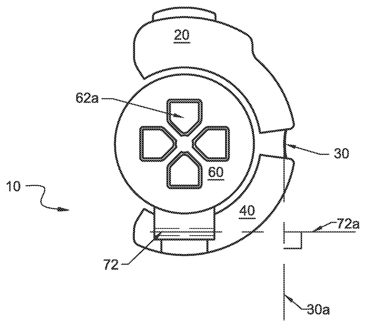
Referring now in detail to the drawings, and in particularFIG. 1, there is shown a controller10with a handlebar clip. The clip allows the controller to easily snap on and off the handlebar of a piece of exercise equipment. A user can then operate the controller, for example to play a video game, while working out on the exercise equipment.
Controller10includes a multimodal controller segment60, having a data input device62athat can range from a button, pad, joystick, or trackball. Multimodal controller segment60is portrayed as a circular disk, generally in the center of controller10. The handlebar clip resides peripherally surrounding controller segment60. More specifically, the handlebar clip includes a first arcuate segment20, a centrally-mounted leaf spring30, and a second arcuate segment40. Controller segment60is pivotally coupled to second arcuate segment40. The pivotal coupling comprises a hinge72having a hinge axis72athat is oriented perpendicular to the leaf spring axis30a.
If controller segment60was pivoted away from the handlebar clip, a C-shaped spring jaw50with an internal circular gap would exist (as can most easily be seen inFIG. 3A, with controller segment60removed for the sake of clarity). The components of C-shaped spring jaw50can be seen inFIG. 2. First arcuate segment20is flexibly connected to second arcuate segment40via one or two leaf springs30. Multimodal controller segment60has a pivotally coupling70that attaches it to second arcuate segment40. Pivotal coupling70may be implemented with a hinge72.
The linear arrangement of segments20,40and leaf spring30places these components in a first plane52x. Multimodal controller segment60may reside in a first orientation54xin which it is oriented in a plane parallel to first plane52x. This parallel orientation is illustrated inFIG. 1. As can be seen inFIG. 2, multimodal controller segment60may alternately be pivoted to a second orientation54yin which it is oriented in a plane perpendicular to first plane52x. Placement of controller segment60in to second orientation54y, provides clearance for a bar80to be disposed within the C-shaped spring jaw50. The second orientation54yplaces multimodal controller segment60parallel to handlebar80where it is upright for use, and supported against the bar. When the multimodal controller segment is removed from bar80, the interference from the bar is no longer present, and segment60can pivot down to orientation54xfor compactness, and for placement onto a base unit.
To attach to the handlebar of an exercise machine, controller10is configured by pivoting controller segment60from first orientation54xto second orientation54y, as shown inFIG. 2. Then as can be seen inFIG. 3, C-shaped spring jaw50is moved towards handlebar80as shown by arrow56. As the open end of spring jaw50contacts bar80, leaf spring30allows segment20to flex away from segment40as shown by arrows58aand58b. When the end of the spring jaw passes the center of the bar, the biasing force of leaf spring30brings segments20and30back toward each other, in a direction opposite arrows58aand58b. Controller10is now mounted on bar80, as can be seen inFIG. 3B, with multimodal controller segment60lying against bar80.
When user grasps handlebar80with their left hand, their thumb would point up locating it on top of the data input device on controller segment60. The other fingers would wrap around the handlebar, with the index finger and middle finger located on top of further data input button22aand22b. Data input device62could be a button, a maintained contact button, a momentary contact button, a directional pushbutton, an analog joystick, a 4-button d-pad, a trackball, or combinations thereof. A similar, mirror-image controller could be provided for the right hand or right handlebar. The controller sends wireless signals to provide the user with remote cooperative player control.
After exercise is completed, the controller or controllers, are removed from the handlebar in an operation that proceeds opposite of that illustrated inFIGS. 3B and 3A. Controller segment60is pivoted back down from second orientation54yto first orientation54x. The hinge and leaf spring along with the three segments collectively comprise an articulating controller.FIG. 4Ashows a main controller housing100with a docking station for each articulating controller. The docking station102is formed as a bar, handlebar or cylindrical section. The bar section has a height102hequivalent to the height of spring jaw50. Accordingly, spring jaw50can be set down on to the cylindrical section with controller segment60sitting on a circular top102c.
Main controller housing100may be configured as a wireless or wired controller. In one embodiment, controller housing100is wired. Section20or40includes a jack40j, and main controller housing100includes a mating jack104m. When plugged in as shown inFIG. 4B, controller10can recharge its batteries and communicate through the jack to utilize the main controller housing's wired connection. The jack and mating jack may be a USB-type jack, for example a mini-USB or micro-USB jack.
While a micro-USB jack can be mounted on any portion of controller10,FIG. 2shows one embodiment with jack40jmounted on second arcuate segment40. Segment40may contain a microprocessor and rechargeable battery. The data input device62a,bwould be connected to jack40jvia wires that pass through, or adjacent, hinge70. Further data input device22a,bwould be connected to jack40jvia wires that pass through, or adjacent, leaf spring30. The wires could be small gauge stranded wire or flat ribbon cable.
Jack40jincludes a sensor that determines whether controller10is uncoupled or coupled to mating jack104m. The microprocessor received a signal from the sensor to indicate if the controller is connected or not. If uncoupled, the microprocessor would draw power from the onboard battery and activate the wireless transceiver. If coupled, the microprocessor would draw power from mating jack104mto recharge the onboard battery. The wireless transceiver would be disabled, and signals from the data input devices62,22would be routed through the micro-USB jack to the main controller housing100.
Accordingly,FIG. 4Bshows that the controller according to the invention may be used like a conventional controller. When the user wants to exercise, one or two controllers10are removed from main controller housing100and clipped to the handlebars of an exercise device. The controller10can automatically switch to wireless mode, for example, Bluetooth or IR or WiFi to communicate with a transceiver located within main controller housing100. Main controller housing may also include a sensor to determine if the controller10is connected or not. If connected, the main controller housing would activate the battery charger, turn off its wireless transceiver, and route signals from data input devices22and62to the video game console. If not connected, the main controller housing would turn the battery charger off and activate the wireless transceiver.
Having described preferred embodiments for a multimodal controller (which are intended to be illustrative and not limiting), it is noted that modifications and variations can be made by persons skilled in the art in light of the above teachings. For example, the type of data input device may be selected from push-buttons, trackballs, mouse, d-pad without detracting from the inventive features. The shape and configuration of the multimodal controller and main controller housing may be varied without affecting the functionality of the inventive device. It is therefore to be understood that changes may be made in the particular embodiments of the invention disclosed which are within the scope and spirit of the invention as outlined by the appended claims. Having thus described the invention with the details and particularity required by the patent laws, what is claimed and desired protected by Letters Patent is set forth in the appended claims.
Claims
- A controller for a software driven processor comprising: an articulating controller having: a first arcuate segment having a first data input device;a second arcuate segment connected by a leaf spring to said first arcuate segment to form a C-shaped spring jaw with said leaf spring biasing said arcuate segments toward each other;a multimodal controller segment having a second data input device pivotally coupled to said second arcuate segment;and a wireless transmitter coupled to said data input devices and disposed within one of said multimodal controller segment or said arcuate segments.
- The controller of claim 1 , wherein said pivotal coupling between said multimodal controller segment and said second arcuate segment comprises a hinge oriented orthogonal to said leaf spring.
- The controller of claim 2 , wherein said arcuate segments and said leaf spring reside in a first plane, and wherein said multimodal controller segment pivots between a first orientation parallel to said first plane and a second orientation perpendicular to said first plane.
- The controller of claim 3 , wherein said arcuate segments can resiliently flex away from each other to pass over a cylindrical bar then bias toward each other to capture the cylindrical bar within said C-shaped spring jaw.
- The controller of claim 4 , wherein said C-shaped spring jaw is adapted to clip onto a handlebar of exercise equipment.
- The controller of claim 5 , wherein said multimodal controller segment is adapted to be supported against a first side of the handlebar facing a user, so that as a user grabs the handlebar their thumb lies over said second data input device.
- The controller of claim 6 , wherein said second data input device is selected from the group consisting of a button, a maintained contact button, a momentary contact button, a directional pushbutton, an analog joystick, a 4-button d-pad, a trackball, and combinations thereof.
- The controller of claim 5 , wherein said first arcuate segment is adapted to be supported against a second side of the handlebar facing away from a user, so that as a user grabs the handlebar their index finger lies over said first data input device.
- The controller of claim 5 , wherein said first arcuate segment includes a third data input device, wherein said first and third data input devices comprising buttons, wherein said first arcuate segment is adapted to be supported against a second side of the handlebar facing away from a user, so that as a user grabs the handlebar their index and middle fingers lie over said two buttons.
- The controller of claim 1 , wherein the software driven processor is selected from the group consisting of a game console, a tablet and a personal computer.
- The controller of claim 1 , further comprising a main controller housing having a docking station, wherein one of said arcuate segments or multimodal controller segment includes a jack for plugging into said docking station for at least one of wired communication and battery recharging.
- The controller of claim 11 , wherein said jack resides on one of said arcuate segments and first data wires extend from said multimodal controller segment through said pivotal coupling to said second arcuate segment.
- The controller of claim 11 , wherein said jack resides on one of said arcuate segments and second data wires extend from said first arcuate segment to said second arcuate segment.
- The controller of claim 11 , wherein said main controller housing has two docking stations to receive two articulating controllers disposed at the right and left hand sides of said main controller housing for integrated cooperative play.
- The controller of claim 14 , wherein said data input device is selected from the group consisting of a button, a maintained contact button, a momentary contact button, a directional pushbutton, an analog joystick, a 4-button d-pad, a trackball, and combinations thereof.
- The controller of claim 15 , wherein said two articulating controllers are adapted for undocking from said main controller housing and for mounting on the right and left handlebars of exercise equipment to provide the user with remote cooperative player control.
Disclaimer: Data collected from the USPTO and may be malformed, incomplete, and/or otherwise inaccurate.