U.S. Pat. No. 9,721,396
COMPUTER AND COMPUTER SYSTEM FOR CONTROLLING OBJECT MANIPULATION IN IMMERSIVE VIRTUAL SPACE
AssigneeColopl Inc
Issue DateOctober 5, 2016
Illustrative Figure
Abstract
Action of a head around which an HMD main body is worn is related to manipulation of an object in an immersive three-dimensional virtual space. Information on a sight in a virtual space may be determined based on information on head inclination sensed with an inclination sensor; an image of the sight in the virtual space may be generated based on the sight information in order to display the sight image in the head mounted display; an object placed on a reference sight line in the virtual space may be identified, the reference sight line being determined in correspondence with a predetermined position in the sight image; and an object the identified object may be manipulated in response to the identification of the object in accordance with action of inclining in a predetermined direction the head around which the head mounted display is worn.
Description
DESCRIPTION OF EMBODIMENTS A computer program that causes a computer to control object manipulation in an immersive virtual space and a computer system for object manipulation in an immersive virtual space according to at least one embodiment will be described below with reference to the drawings. In the drawings, the same components are labeled with the same reference characters. FIG. 1is an overall schematic view of a head mounted display (hereinafter referred to as “HMD”) system100using an HMD according to at least one embodiment. The HMD system100includes an HMD main body110, a computer (control circuit section)120, a position tracking camera (position sensor)130, and an external controller140, as shown inFIG. 1. The HMD110includes a display112and a sensor114. The display112is a non-transmissive display device configured so as to completely cover a user's sight, and the user is thereby allowed to view only a screen displayed in the display112. Since the user who wears the non-transmissive HMD110entirely loses sight of the outside world, there is achieved a display aspect in which the user is completely immersed in a virtual space displayed by an application executed in the control circuit section120. The sensor114provided in the HMD110is fixed to a portion in the vicinity of the display112. The sensor114includes a terrestrial magnetism sensor, an acceleration sensor, and/or an inclination (angular velocity, gyro) sensor and can sense a variety of types of motion of the HMD110(display112) worn around the user's head by using at least one of the sensors. The angular velocity sensor, in particular, can sense angular velocities of the HMD110around the three axes thereof in a time course in accordance with motion of the HMD110and determine a temporal change in angle (inclination) around each of the axes, as shown inFIG. 2. Angular information data that can be sensed with the inclination sensor will be ...
DESCRIPTION OF EMBODIMENTS
A computer program that causes a computer to control object manipulation in an immersive virtual space and a computer system for object manipulation in an immersive virtual space according to at least one embodiment will be described below with reference to the drawings. In the drawings, the same components are labeled with the same reference characters.
FIG. 1is an overall schematic view of a head mounted display (hereinafter referred to as “HMD”) system100using an HMD according to at least one embodiment. The HMD system100includes an HMD main body110, a computer (control circuit section)120, a position tracking camera (position sensor)130, and an external controller140, as shown inFIG. 1.
The HMD110includes a display112and a sensor114. The display112is a non-transmissive display device configured so as to completely cover a user's sight, and the user is thereby allowed to view only a screen displayed in the display112. Since the user who wears the non-transmissive HMD110entirely loses sight of the outside world, there is achieved a display aspect in which the user is completely immersed in a virtual space displayed by an application executed in the control circuit section120.
The sensor114provided in the HMD110is fixed to a portion in the vicinity of the display112. The sensor114includes a terrestrial magnetism sensor, an acceleration sensor, and/or an inclination (angular velocity, gyro) sensor and can sense a variety of types of motion of the HMD110(display112) worn around the user's head by using at least one of the sensors. The angular velocity sensor, in particular, can sense angular velocities of the HMD110around the three axes thereof in a time course in accordance with motion of the HMD110and determine a temporal change in angle (inclination) around each of the axes, as shown inFIG. 2.
Angular information data that can be sensed with the inclination sensor will be described with reference toFIG. 2. XYZ coordinates are defined with respect to the head of the user who wears the HMD, as shown inFIG. 2. The Y axis extends in the vertical direction in which the user stands up. The Z axis is orthogonal to the Y axis and extends in the direction in which the center of the display112and the user are connected to each other. The X axis is an axis extending in the direction orthogonal to the Y axis and the Z axis. The inclination sensor senses an angle around each of the axes (that is, inclination determined by the yaw angle representing rotation about the Y axis, the pitch angle representing rotation about the X axis, and the roll angle representing rotation about the Z axis), and a motion sensing section210determines angular (inclination) information data as information on the sight on the basis of the time-course change.
Referring back toFIG. 1, the computer120provided in the HMD system100functions as the control circuit section120that causes the user who wears the HMD to be immersed in a three-dimensional virtual space and further causes the user to perform action based on the three-dimensional virtual space. The control circuit section120may be configured as hardware separate from the HMD110, as shown inFIG. 1. The hardware can be a computer, such as a personal computer or a server computer that operates over a network. That is, the hardware can be an arbitrary computer including a CPU, a main storage, an auxiliary storage, a transceiver, a display section, and an input section connected to each other via a bus.
The control circuit section120may instead be accommodated as an object manipulator in the HMD110. In this case, the control circuit section120can implement the entirety or only some of the functions of the object manipulator. In the case where only some of the functions are implemented, the remaining functions may be implemented in the HMD110or a server computer (not shown) that operates over a network.
The position tracking camera (position sensor)130provided in the HMD system100is so connected to the control circuit section120that they can communicate with each other and has the function of tracking the position of the HMD110. The position tracking camera130is achieved by using an infrared sensor and a plurality of optical cameras. The HMD system100, which includes the position tracking camera130and senses the position of the HMD around the user's head, can accurately relate the virtual space positions of the virtual camera/immersed user in the three-dimensional virtual space to each other and identify the virtual space positions.
More specifically, the position tracking camera130is virtually provided on the HMD110, as shown inFIG. 3by way of example, and senses, in a time course in correspondence with the user's motion, actual space positions of a plurality of sensing points where infrared light is sensed. A temporal change in the angle around each of the axes according to the motion of the HMD110can then be determined on the basis of the time-course change in the actual space positions sensed by the position tracking camera130.
Referring back toFIG. 1, the HMD system100includes the external controller140. The external controller140is a typical user terminal and can be a smartphone shown inFIG. 1but is not limited thereto. The external controller140can instead, for example, be a portable device terminal including a touch display, such as a PDA, a tablet computer, a game console, or a notebook PC. That is, the external controller140can be an arbitrary portable device terminal including a CPU, a main storage, an auxiliary storage, a transceiver, a display section, and an input section connected to each other via a bus. The user can perform a variety of types of touch action including tapping, swiping, and holding on the touch display of the external controller140.
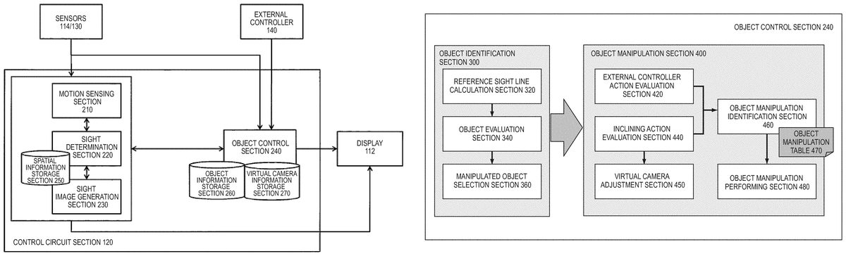
The block diagram ofFIG. 4shows the configuration of primary functions of the control circuit section120and other components therearound to implement object manipulation in the three-dimensional virtual space according to at least one embodiment. The control circuit section120primarily receives inputs from the sensors114/130and the external controller140, processes the inputs, and outputs results of the processing to the display112. The control circuit section120primarily includes the motion sensing section210, a sight determination section220, a sight image generation section230, and an object control section240and interacts with a variety of tables in a spatial information storage section250, an object information storage section260, a virtual camera information storage section270, and other sections to process a variety of pieces of information.
The motion sensing section210measures data on motion of the HMD110worn around the user's head on the basis of motion information inputted from the sensors114/130. In at least one embodiment, in particular, angular information sensed in a time course with the inclination sensor114and position information sensed in a time course with the position tracking camera130are determined.
The sight determination section220determines sight information of the virtual cameras in the three-dimensional virtual space on the basis of three-dimensional virtual space information stored in the spatial information storage section250, angular information sensed with the inclination sensor114, and sensed information in the direction of the field of view of the virtual cameras based on the position information sensed with the position sensor130. The sight image generation section230can then generate a sight image of part of a 360-degree panoramic image on the basis of the determined sight information. As the sight image, two two-dimensional images for the right and left eyes are generated and superimposed on each other in the HMD, and the superimposed image displayed in the HMD is presented to the user in the form of a three-dimensional image, as shown inFIGS. 11 to 13.
Referring back toFIG. 4, the object control section240identifies an object to be manipulated on the basis of object information of an object in the three-dimensional virtual space that is stored in the object information storage section260, information from the sensors114/130, and the user's instructions from the external controller140. The object control section240receives an instruction of predetermined user operation to be performed on the identified object to be manipulated, adjusts virtual camera information stored in the virtual camera information storage section270and manipulates the object to be manipulated, and outputs a result of the manipulation to the display112of the HMD. Specific processes of the object manipulation will be described in association withFIG. 5and the following figures.
InFIG. 4, elements drawn as functional blocks that carry out a variety of processes can be configured by a CPU, a memory, and other integrated circuits in a hardware sense and can be achieved by a variety of programs loaded in the memory in a software sense. A person skilled in the art therefore understands that these functional blocks can be achieved by any of the hardware, the software, and a combination thereof (the same holds true forFIG. 8, which will be described later).
The process of identifying an object to be manipulated and the process of manipulating the object to be manipulated that are carried out by the sight determination section220, the sight image generation section230, and the object control section240shown inFIG. 4will be described in detail with reference toFIGS. 5 to 10.FIG. 5is a stereoscopic view diagrammatically showing an example of the arrangement of a virtual camera1, cylindrical objects O1and O2, and a cubic object O3in an immersive three-dimensional virtual space2according to at least one embodiment. The sight captured with the virtual camera1is displayed as the sight image in the display of an immersed user. Since the head of the user who wears the HMD inclines downward, the virtual camera1is also oriented to a point below a horizontal line, as shown inFIG. 5. The cylindrical object O1is placed at the front end of the (arrowed) center line of the sight. Further, the cylindrical object O2is placed on the right in the sight, and the cubic object O3is placed on the left in the sight.
FIG. 6shows the arrangement in the diagrammatic view ofFIG. 5in detail. As shown inFIG. 6, in a virtual space in which a horizontal plane is defined by the XZ coordinates and the vertical direction is defined by the Z axis, the virtual camera1is placed in a position (Xcam, Ycam, Zcam). The coordinates of the position are determined on the basis of the position information sensed with the position tracking camera. The field of view of the virtual camera1has a predetermined range, and the sight is defined on the basis of the range of the field of view. A sight image is generated on the basis of the defined sight. A sight reference sight line Lstdand sight boundary lines Lbd1and Lbd2with respect to the reference sight line are defined. The reference line Lstdis so defined as to correspond to a predetermined position (a central point, for example) in the sight image.
The objects O1to O3are placed in a position (XO1, 0, ZO1), a position (XO2, 0, ZO2), and a position (XO3, 0, ZO3), respectively, in the XZ plane by way of example. Since an object, of course, has a fixed size, the coordinate position of the object may be defined in the form of a coordinate range. In the relationship in the example inFIG. 6between the position and orientation of the virtual camera and the positions where the objects are placed, the object O1is placed on the reference sight line Lstd. As a result, the object O1is identified as an object to be manipulated.
FIGS. 7A and 7Beach show an outline of manipulation performed on the object O1identified inFIG. 6.FIG. 7Adiagrammatically shows an example of manipulation of the virtual camera and the object in the three-dimensional virtual space according to at least one embodiment. When the object O1to be manipulated is identified, the position of the virtual camera1is fixed, as shown inFIG. 7A. In this state, when the user performs HMD action of further inclining the head, object manipulation related in advance to the action is performed on the object O1. In the description, the user performs HMD inclining action of moving the head in the vertical direction, and the object O1is moved also in the three-dimensional virtual space in accordance with the distance of the head movement in the Y-axis direction to a position having coordinates (XO1, YO1, ZO1). In this process, the orientation of the virtual camera is adjusted in terms of angle also in the Y-axis direction in such a way that a reference sight line LOP′always gives a sight reference position (for example, the central position in the sight image is maintained).
InFIG. 7A, an object O1′ having moved in the Y-axis direction is further rotated. The object rotation can also be related to predetermined HMD inclining action (action of inclining HMD in horizontal direction, for example), as in the object movement. The object rotation can instead be related to predetermined action performed on the external controller140(swiping on touch display, for example).
FIG. 7Bdiagrammatically shows another example of manipulation of the virtual camera and the object in the three-dimensional virtual space according to at least one embodiment. In the example inFIG. 7A, after the object O1to be manipulated is identified, the position of the virtual camera1is fixed, and the orientation of the camera is then adjusted. In contrast, in the example inFIG. 7B, the position of the virtual camera is not fixed, but the orientation thereof is fixed. That is, when the object O1is moved in the Y-axis direction to the position having the coordinates (XO1, YO1, ZO1), the position of the virtual camera1is also moved in the Y direction to the position having coordinates (Xcam, Ycam+YO1, Zcam).
The control of the position and orientation of a virtual camera is not limited to the process example inFIG. 7A or 7B. That is, a person skilled in the art should understand that there can be employed any process aspect in which the position and/or orientation of a virtual camera is so adjusted that the reference sight line LOP′always gives the sight reference position (for example, the central position in the sight image is maintained).
Processes relating to the object manipulation in the three-dimensional virtual space having been described above with reference toFIGS. 6, 7A, and 7Bwill be described in more detail with reference toFIGS. 8 to 10.FIG. 8is a detailed functional block diagram showing blocks that form the object control section240having been described with reference toFIG. 4. The object control section240includes an object identification section300for identifying an object to be manipulated and an object manipulation section400for manipulating the identified object to be manipulated, as shown inFIG. 8.
The object identification section300identifies an object placed on the reference sight line shown inFIG. 6in the three-dimensional virtual space on the basis of the user's HMD inclining action. To this end, the object identification section300includes a reference sight line calculation section320, which calculates a reference sight line that is present in the three-dimensional virtual space and related to a reference point in a sight image, an object evaluation section340, which evaluates whether an object is placed on the reference sight line, and a manipulated object selection section360, which selects the object as an object to be manipulated if the object is placed on the reference sight line.
On the other hand, the object manipulation section400responds to the identification of an object to be manipulated performed by the object identification section300and performs on the object to be manipulated manipulation according to the user's action of inclining the head around which the HMD is worn in a predetermined direction. To this end, the object manipulation section400includes an external controller action evaluation section420, which evaluates whether the external controller has received the user's touch action, an inclining action evaluation section440, which evaluates the user's HMD inclining action (inclination direction), a virtual camera adjustment section450, which adjusts the position or direction of a virtual camera when object manipulation is performed, an object manipulation identification section460, which identifies object manipulation performed on an object to be manipulated in accordance with an object manipulation table470, and an object manipulation performing section480, which performs the object manipulation to generate a sight image.
The object manipulation identification using the object manipulation table470will be described with reference toFIG. 9.FIG. 9is a schematic view showing an example of correspondence between the user's action and object manipulation, on the basis of which the object manipulation table470is created. When the manipulated object selection section360selects an object to be manipulated, and the user continuously performs “tapping” on the external controller, the object to be manipulated can be “caught” in the three-dimensional virtual space. The “tapping” is presented only by way of example, and there may be used any other HMD action or input action that is performed by the user and can be uniquely related to object manipulation in a state in which an object to be manipulated is selected.
Object manipulation after the “catching” described above can be determined in accordance with the object manipulation table470. The user's action includes not only the HMD inclining action (column) but also touch action performed on the external controller (row), and combinations of these types of user's action allow identification of object manipulation. For example, in a case where the HMD action is “upward or downward inclination” and the user further performs “tapping” on the touch display as external controller action, the overall action is taken as an “object releasing” action instruction. Similarly, in a case where the HMD action is “upward or downward inclination” and the user further performs “swiping” in cooperation with the external controller, the overall action is taken by the object manipulation identification section460as an “object rotating” action instruction; when the user further performs “holding” on the external controller, the overall action is taken as an “object upward or downward movement” action instruction; and when the user further performs nothing as external controller action, the overall action is taken as an “object frontward or rearward movement” action instruction. The object manipulation performing section480then performs each of the action instructions.
The HMD action is not limited to “upward or downward inclination” and may be any inclination action that is uniquely identifiable. Further, only one of HMD inclining action and external controller action may be accepted as the user's action and related to object manipulation. However, in a case where it is desired to provide a large number of object manipulation types, it is preferable to use combinations of HMD inclining action and external controller action. The user's HMD inclining action, which can be performed only by causing the user who wears the HMD to move his/her own head, is easy for the user. Further, it can be said that touch action performed on the external controller is also easy for the user because the user only needs to perform “tapping,” “swiping,” or “holding” in any position on the touch display.
The procedure of the processes for object manipulation in the three-dimensional virtual space according to at least one embodiment will next be described in detail with reference toFIG. 10. The object manipulation processes are achieved by interaction among the external controller140, the position tracking camera (position sensor)130, the HMD110, and the computer (control circuit section)120.
In the object manipulation processes, the motion sensing section210senses a variety of pieces of information on the HMD. That is, in step S130-1, the position sensor connected to the computer120and capable of sensing the HMD senses the position of the HMD110. In step S100-1, the inclination sensor provided in the HMD connected to the computer120senses the inclination of the HMD110. In step S120-1, the motion sensing section210determines the position information and the inclination information, and the sight determination section220determines the sight information in the three-dimensional virtual space on the basis of the position information and/or the inclination information on the HMD110described above.
After the sight information is determined, in the subsequent step S120-2, the sight image generation section230generates a sight image to be displayed in the HMD on the basis of the sight information described above. Further, in step S120-3, the reference sight line calculation section320determines the reference sight line Lstd. The reference sight line Lstdis determined in correspondence with a predetermined position in the sight image. The predetermined position is preferably but not necessarily the central point of the sight image and may be any settable position in the sight image. Further, the reference point is preferably so displayed in the form of a mark of some kind (palm icon, for example) as to be superimposed on the sight image described above.
Thereafter, in step S100-2, the sight image is displayed in the HMD. A plurality of objects each of which is a candidate of an object to be manipulated later are displayed in the sight image. In the state in which the sight image is displayed in the HMD, the user who wears the HMD performs head inclining action to perform positioning in such a way that at least one of the plurality of objects placed in the three-dimensional virtual space corresponds to the predetermined position in the sight image.
In step S120-4, the object evaluation section340evaluates whether at least one object has been positioned in the predetermined position described above in the sight image; that is, whether an object has been placed on the reference sight line in the three-dimensional space. In the case where an object has been placed on the reference sight line, in step S120-5, the manipulated object selection section360selects the object as an object to be manipulated. If a plurality of objects placed on the reference sight line are present, the manipulated object selection section360may select one object closest to the position of the virtual camera in the three-dimensional virtual space; that is, the point of view.
In step S140-1, it is evaluated whether the user has performed touch action (“tapping,” in particular) on the external controller140after the selection of the object in step S120-5. In the case where the user has performed touch action, in step S120-6the object identification section300responds to the touch action, and identification of an object to be manipulated is completed. In this state, the sight image is displayed in the HMD in an aspect in which the user has “caught” the object to be manipulated. On the other hand, in the case where the user has performed no touch action, the control returns to step S130-1and step S100-1in the initial stage, and the information on the position and inclination of the HMD is continuously sensed.
In the state in which the user has caught the object to be manipulated, the user further performs external controller action (step S140-2) and HMD inclining action (step S100-3). In response to the action, the external controller action evaluation section420and the inclining action/direction evaluation section440perform action evaluation, and in step S120-7, the object manipulation identification section460identifies corresponding manipulation performed on the object to be manipulated. The corresponding manipulation has been described with reference toFIG. 9. Unique object manipulation is determined on the basis a combination of HMD inclining action; for example, in the vertical direction (HMD upward or downward inclination action) and external controller action.
In step S120-8and the following steps, actual manipulation is performed on the object to be manipulated, and a result of the manipulation is displayed in the HMD. That is, in step S120-8, the virtual camera adjustment section450adjusts the position and direction of the virtual camera shown inFIGS. 7A and 7B. In the subsequent step S120-9, the object manipulation performing section480performs specific manipulation on the object to be manipulated, as shown inFIGS. 7A and 7Bagain. In step S120-10, a series of images resulting from the manipulation are generated, and in step S100-4, the images resulting from the manipulation are displayed in the HMD in a time course.
Examples of Screen Display
On the basis of the above description,FIGS. 11 to 13show screen examples displayed in the HMD that are implemented on the basis of at least one embodiment and relate to object manipulation in the three-dimensional virtual space. In the examples, assume a building block game application that allows manipulation of building block objects placed in an immersive three-dimensional virtual space. More specifically, assume a building block game application in which HMD head action is related to manipulation of moving a building block object in a specific direction or any other manipulation so that the user can manipulate the building block object by moving the head around which the HMD is worn. InFIGS. 11 to 13, two images for the right and left eyes are displayed, and when the images are displayed in the HMD, they are superimposed on each other as if the user sees a three-dimensional image, as described above.
InFIG. 11, a large number of building block objects are placed on a plane in the three-dimensional virtual space. Further, a mark having a palm shape is displayed at the center of a sight image. The user then performs HMD inclining action for positioning in such a way that the mark overlaps with any of the building block objects to advance the game. The user selects a single building block object in the positioning process and then combines HMD inclining action with external controller action to manipulate the building block object in accordance with an object manipulation rule, such as those shown inFIGS. 7A and 7B.FIG. 12shows a state in which the selected, caught building block object is moved to a predetermined position.FIG. 13shows a state in which a single building block object is lifted upward by HMD inclining action in the vertical direction and the lifted building block object is to be stacked on another building block object placed in a position adjacent to the lifted building block object.
As described above, according to the present disclosure, simple action of the head of a user who wears an HMD allows object manipulation in an immersive three-dimensional virtual space. Further, combining head action using the HMD with external controller action allows more complicated object manipulation. Based on the features described above, the present disclosure can provide a novel game operation aspect in a game application using an HMD.
At least one embodiment has been described above, but the present disclosure is not limited to the at least one embodiment described above. A person skilled in the art will understand that a variety of modification can be made to the at least one embodiment without departing from the spirit and scope of the present disclosure set forth in the claims.
DESCRIPTION OF SYMBOLS
1Virtual camera2Immersive three-dimensional virtual space100HMD system110HMD112Display114Inclination sensor (gyro sensor)120Computer (control circuit section)130Position sensor (position tracking camera)140External controller210Motion sensing section220Sight determination section230Sight image generation section240Object control section250Spatial information storage section260Object information storage section270Virtual camera information storage section300Object identification section320Reference sight line calculation section340Object evaluation section360Manipulated object selection section400Object manipulation section420External controller action evaluation section440Inclining action evaluation section450Virtual camera adjustment section460Object manipulation identification section470Object manipulation table480Object manipulation performing section
Claims
- A computer comprising a CPU and a memory having a computer program stored therein wherein the computer program, when executed by the CPU causes the CPU to perform operations comprising: determining information on a sight in a three-dimensional virtual space based on three-dimensional virtual space information stored in the memory and information on inclination sensed with an inclination sensor provided in a head mounted display connected to the computer;generating an image of the sight in the three-dimensional virtual space based on the sight information in order to display the sight image in the head mounted display;identifying an object in the generated sight image placed on a reference sight line in the generated sight image in the three-dimensional virtual space, the reference sight line being determined in correspondence with a predetermined position in the generated sight image;and manipulating the identified object in the three-dimensional virtual space in accordance with action of inclining the head mounted display in a predetermined direction.
- The computer according to claim 1 , wherein the determining sight information based further on information on a position of the head mounted display that is sensed with a position sensor connected to the computer and capable of sensing the head mounted display.
- The computer according to claim 1 , wherein in a case where a plurality of objects are placed on the reference sight line, the identifying an object in the generated sight image comprises selecting an object closest to a point of view in the three-dimensional virtual space.
- The computer according to claim 1 , wherein the predetermined position is set at a central point of the sight image.
- The computer according to claim 1 , wherein the predetermined direction is a vertical direction.
- The computer according to claim 1 , wherein the manipulating the identified object in the three-dimensional virtual space comprises manipulating the identified object in cooperation with an external controller connectable to the computer.
- The computer according to claim 6 , wherein the external controller includes a touch display, and the manipulation performed on the identified object in cooperation with the external controller is performed in accordance with touch action including any of tapping, swiping, and holding performed on the touch display.
- A computer system comprising a computer and a head mounted display connected to the computer and including an inclination sensor, wherein the computer is configured to perform operations comprising: determining information on a sight in a three-dimensional virtual space based on stored three-dimensional virtual space information and information on inclination sensed with the inclination sensor, generating an image of the sight in the three-dimensional virtual space based on the sight information in order to display the sight image in the head mounted display, identifying an object in the generated sight image placed on a reference sight line in the generated sight image in the three-dimensional virtual space, the reference sight line being determined in correspondence with a predetermined position in the generated sight image, and manipulating the identified object in the three-dimensional virtual space in accordance with action of inclining the head mounted display in a predetermined direction.
- The computer system according to claim 8 , further comprising a position sensor connected to the computer and capable of sensing the head mounted display, wherein the sight information is determined based further on information on a position of the head mounted display sensed with the position sensor.
- The computer system according to claim 8 , further comprising an external controller connectable to the computer, wherein the manipulation performed on the identified object is performed in accordance with touch action performed on a touch display provided in the external controller.
- A non-transitory computer-readable medium having a computer program stored therein, the computer program when read and executed by a processor causing the processor to perform operations comprising: determining information on a sight in a three-dimensional virtual space based on stored three-dimensional virtual space information and information on sensed inclination of a head mounted display;generating an image of the sight in the three-dimensional virtual space based on the sight information in order to display the sight image in the head mounted display;identifying an object in the generated sight image placed on a reference sight line in the generated sight image in the three-dimensional virtual space, the reference sight line being determined in correspondence with a predetermined position in the generated sight image;and manipulating the identified object in the three-dimensional virtual space in accordance with action of inclining the head mounted display in a predetermined direction.
Disclaimer: Data collected from the USPTO and may be malformed, incomplete, and/or otherwise inaccurate.