U.S. Pat. No. 9,713,768
GAME CONTROLLER
AssigneeRAZER (ASIA-PACIFIC) PTE. LTD.
Issue DateMarch 24, 2015
Illustrative Figure
Abstract
The present invention is a game controller including a housing; a plurality of game controls disposed on a first side of the housing; a lever disposed on a second side of the housing; a first switch configured to contact a first end region of the lever; and a second switch configured to contact a second end region of the lever, wherein the lever is configured to pivot between a neutral position in which the lever returns when no force is applied thereon, a first position in which the first switch is activated and a second position in which the second switch is activated. In another aspect, a lever assembly is also disclosed.
Description
DETAILED DESCRIPTION The following detailed description refers to the accompanying drawings that show, by way of illustration, specific details and embodiments in which the invention may be practiced. These embodiments are described in sufficient detail to enable those skilled in the art to practice the invention. Other embodiments may, be utilized and structural, and logical changes may be made without departing from the scope of the invention. The various embodiments are not necessarily mutually exclusive, as some embodiments can be combined with one or more other embodiments to form new embodiments. In order that the invention may be readily understood and put into practical effect, particular embodiments will now be described by way of examples and not limitations, and with reference to the figures. Various embodiments provide a gaming device having a set of game controls on its top panel and its front including, for example, joysticks, action buttons, directional gamepads, multifunction triggers and/or buttons; and another set of triggers placed on its underside (or bottom), designed specifically for triggering by a user's middle finger. For example, the top panel and the front may refer to the top panel102and the front110ofFIG. 1B. In some embodiments, the other set of triggers may either share some gaming functions of the buttons triggered by the user's index finger or simply carry other functions in gaming. For example, additional multi-function triggering features may be added on an existing gamepad or gaming device for the user's middle fingers to use so as to provide more advantage in a gaming environment where additional commands with speed is critical in playing and/or winning a game. Utilizing the movement of the fingers such as the middle fingers or the ring fingers or the little fingers (pinkies) therefore adds advantage to the user. Various embodiments provide a middle-finger flick, ...
DETAILED DESCRIPTION
The following detailed description refers to the accompanying drawings that show, by way of illustration, specific details and embodiments in which the invention may be practiced. These embodiments are described in sufficient detail to enable those skilled in the art to practice the invention. Other embodiments may, be utilized and structural, and logical changes may be made without departing from the scope of the invention. The various embodiments are not necessarily mutually exclusive, as some embodiments can be combined with one or more other embodiments to form new embodiments.
In order that the invention may be readily understood and put into practical effect, particular embodiments will now be described by way of examples and not limitations, and with reference to the figures.
Various embodiments provide a gaming device having a set of game controls on its top panel and its front including, for example, joysticks, action buttons, directional gamepads, multifunction triggers and/or buttons; and another set of triggers placed on its underside (or bottom), designed specifically for triggering by a user's middle finger. For example, the top panel and the front may refer to the top panel102and the front110ofFIG. 1B. In some embodiments, the other set of triggers may either share some gaming functions of the buttons triggered by the user's index finger or simply carry other functions in gaming.
For example, additional multi-function triggering features may be added on an existing gamepad or gaming device for the user's middle fingers to use so as to provide more advantage in a gaming environment where additional commands with speed is critical in playing and/or winning a game. Utilizing the movement of the fingers such as the middle fingers or the ring fingers or the little fingers (pinkies) therefore adds advantage to the user.
Various embodiments provide a middle-finger flick, pull and or push activation switch for a gaming device.
In an aspect, a game controller200is provided as shown inFIG. 2. The game controller200includes a housing202; a plurality of game controls204disposed on a first side of the housing202; a lever206disposed on a second side of the housing202; a first switch208configured to contact a first end region of the lever206; and a second switch210configured to contact a second end region of the lever206, wherein the lever206is configured to pivot between a neutral position in which the lever206returns when no force is applied thereon, a first position in which the first switch208is activated and a second position in which the second switch210is activated.
In the context of various embodiments, the term “game controller” may interchangably be referred to as gaming controller, gaming device, gamepad, video game controller, game controller unit, controller, controller unit, game console, gaming console, gaming console unit, console unit, gaming input device or gaming input unit. It should be understood and appreciated that a game controller, for example, the game controller200may generally refer to any device that is configured to send signals to execute a game program or gaming function. The game program may be but is not limited to a video game program or a computer game program. For example, the game controller200may be for use with a PLAYSTATION system (made by Sony Corporation) or a XBOX system (made by Microsoft Corporation).
As used herein, the term “plurality of game controls” refers to input components of the game controller200that is assessed and activated by a user to execute a game program or gaming function.
In various embodiments, the plurality of game controls204may include at least one of a pushbutton, a joystick or a directional pad. For example, the pushbutton, the joystick and the directional pad may be the action button106, the joystick104and the directional gamepad108ofFIG. 1A, respectively.
For example, the plurality of game controls204may be triggered by a user's thumb(s) and/or index finger(s).
The term “lever” may broadly mean any mechanical device or actuator that can be moved between at least two positions. For example, when the lever206is actuated, it usually transmits a force to an additional trigger located at one of the at least two positions. The lever206may be in contact with the additional trigger. For example, the additional trigger may be the first switch208or the second switch210.
For example, the lever206may be of an elongate structure having end regions that may be configured to contact or make contact with additional triggers located at two positions. In this context, the phrase “configured to contact” generally refers to making direct (physical) contact. For example, when an additional trigger (or switch) is “configured to contact” an end region of a lever, this may mean that a surface of the additional trigger abuts or touches a surface of the end region of the lever. In a different example, the phrase “configured to contact” may refer to making indirect contact, for example, the additional trigger may come into direct contact with an intermediate component such as an adaptor or a gear, which then make direct contact to the end region of the lever. By contacting the additional trigger to the end region of the lever, an exerting force is applied onto the additional trigger; thereby activating it.
The lever206may be pivotable about a pivot point to move from one of the two positions to the other. The lever206may resume the neutral position which is a position where the lever does not make contact with any of the additional triggers located at the two positions. For example, if the contact surfaces of the additional triggers lie on a plane, the neutral position may be a position where the lever is parallel to this plane. The lever206may resume the neutral position when no force is applied on the lever206. The lever206may resume the neutral position due to a bias, for example, a spring. In other embodiments, the lever206may return to its neutral position due to the spring bias of the switches208and210.
As used herein, the pivot point may be proximate to the second side of the housing. For example, the pivot point may be arranged to be located inside the housing or sitting on a printed circuit board (PCB) within the housing or an internal part of the housing such that the lever pivoting about the pivot point is disposed on the second side of the housing. In other examples, the pivot point may be arranged at the second side of the housing.
As used herein, the phrase “end region” may refer to the corners, edges, ends or substantially ends of a lever. The end region may have a surface, for example, a bottom surface, configured to contact or abut the switch (e.g., the first switch208or the second switch210).
In various embodiments, the lever206may be configured to pivot from the first position to the second position via the neutral position. The lever206may be configured to pivot about a pivot point, as defined above.
In various embodiments, the lever206may be configured to pivot from the second position to the first position via the neutral position.
As used herein, the term “switch” usually refers to an electrical or electro-mechanical device with contacts and by changing the position of the switch alters the states of the contacts. For example, one state may relate to turning a device on while another state may relate to turning the device off. In this context, the switch does not refer to a power on-off switch for the game controller.
The first switch208and the second switch210may be but are not limited to biased switches (e.g. pushbutton switches), toggle switches, or a combination of both.
In one example, the lever206and the first and second switches208,210may be integrated into a switch package. For example, the switch package may be a rocker switch.
As used herein, the term “activated” may interchangably be referred to as triggered, turned on, initiated, or started.
In the context of various embodiments, the term “side” with respect to the housing202means a face of the housing202. For example, the “side” may refer but is not limited to the top panel102or the front110of the gaming device ofFIG. 1B. The underside or bottom as opposed to the top panel102may also be referred to as a “side” of housing202.
In various embodiments, the first side of the housing202may be an upper side of the housing202and the second side of the housing202may be an underside of the housing202.
Various embodiments provide a game controller with additional triggers or switches which may be activated by actuating a lever which is configured to make contact with the additional triggers. The additional triggers may be located on the underside of a housing of the game controller while the upper side of the housing is the side accommodating a plurality of game controls which are or may be triggered by a user's thumb(s) and/or index finger(s). The lever may be actuated by the movement of a finger, for example, the user's middle finger when the game controls are triggered using the user's thumb(s) and/or index finger(s). The additional triggers are not the same as and do not refer to the game controls. In some examples, the lever may also be actuated by the user's ring finger or little finger (pinky). The lever may be best actuated by the movement of the user's middle finger due to the middle finger's higher dexterity as compared to the ringer finger and little finger. The lever is pivotable about a pivot point and may allow the user's finger to glide along its surface to reach and activate the additional triggers which are usually placed apart from one another. The lever advantageously provides a guide for the user's fingers so that the user can move from one of the additional triggers to another quickly and accurately. Such fast activation of the additional triggers are usually required in gaming in order to achieve good gaming results or to win a game. The additional trigger may be activated when the lever is actuated by a force exerted into the additional trigger, for example, the force may be exerted directly from above the additional trigger which allows the force to be in the same direction as the movement of the additional trigger. In another example, the additional trigger may be, activated and move in a direction when the lever is actuated by a force applied along the lever, the force being in another direction substantially normal to the direction in which the additional trigger moves. In some examples, a force may be applied any where along the lever away from the pivot point to activate the additional triggers.
In various embodiments, the first switch208may be activated when a force into the direction of the first switch208is applied to the lever206.
In various embodiments, the second switch210may be activated when another force into the direction of the second switch210is applied to the lever206.
In further embodiments, the lever206may be configured to pivot about a pivot point to the first position or the second position by exerting a pulling force or a flicking force or a pushing force on the lever206into the direction of the first switch208and the direction of the second switch210, respectively, wherein the pulling force is a force exerted in an opposite direction to the flicking force.
FIG. 3Ashows an exemplary lever300configured to activate a first switch302and a second switch304in accordance to various embodiments. InFIG. 3A, the lever300may experience a pulling force or a flicking force or a pushing force, for example, as shown by left-pointing arrows306,308or right-pointing arrows310,312or upward pointing arrows314,316, respectively.
In the context of various embodiments, the pulling force and/or the flickering force may be a force exerted along the lever300and is in a direction normal to the actuation movement of the first switch302or the second switch304. The pushing force may be a force exerted on the lever300and into the first switch302or the second switch304, i.e., in the same direction as the actuation movement of the first switch302or the second switch304.
For example,FIG. 3Bshows the activation of the first switch302by exerting the pulling force, for example, as shown by the left-pointing arrows306,308or the pushing force, for example, as shown by the upward pointing arrows314on the lever300.
For example,FIG. 3Cshows the activation of the second switch304by exerting a flicking force, for example, as shown by the right-pointing arrows310,302or a pushing force, for example, as shown by the upward pointing arrows316on the lever300.
For example, in various context, the lever300, the first switch302and the second switch304may be the lever206, the first switch208and the second switch210ofFIG. 2.
In various embodiments, the lever206(for example, the lever300ofFIGS. 3A to 3C) may be an arc-shaped lever having a concave part318located between the first end region320and the second end region322of the lever300, wherein the first end region320is located opposite to the second end region322.
The end region may further include to a leg or an extension or a protrusion. For example, the leg, the extension or the protrusion may be formed or disposed on another surface of the end region, this other surface being different from the surface contacting the switch. In one example, the other surface may be the top surface with reference to the bottom surface of the end region which may be configured to contact or abut the switch. The concave part318may be located between the leg, the extension or the protrusion of the first end region320and the leg, the extension or the protrusion of the second end region322of the lever300.
In the context of various embodiments, the phrase “concave part” may be but is not limited to being interchangably referred to as a groove, a sunken area or a sunken part, a caved part, a curved part, a dip, a dish, a crescent part/feature, a moon-shaped part/feature, or a recessed portion relative to the top edge of the leg/extension/protrusion. In some examples, a plurality of projections such as “small bumps” may be formed on the leg, the extension or the protrusion. The plurality of projections or small bumps provide better grip or more friction between the leg, the extension or the protrusion and a user's finger contacting the leg, the extension or the protrusion during gameplay.
In various embodiments, the lever206(for example, the lever300ofFIGS. 3A to 3C) may be configured to pivot about the pivot point to the first position by exerting the pulling force, for example, as shown by the left-pointing arrow306from inside of the concave part318towards the first end region320of the lever300.
In various embodiments, the lever206(for example, the lever300ofFIGS. 3A to 3C) may be configured to pivot about the pivot point to the second position by exerting the flickering force, for example, as shown by the right-pointing arrow312from inside of the concave part318towards the second end region322of the lever300.
In various embodiments, the lever206(for example, the lever300ofFIGS. 3A to 3C) may be configured to pivot about the pivot point to the first position or the second position by exerting the pushing force, for example, as shown by the upward pointing arrows314,316onto the first or second end region320,322of the lever300respectively.
In various embodiments, the second switch210may be deactivated when the lever206is in the first position. The first switch208may be deactivated when the lever206is in the second position. As used herein, the term “deactivated” has the opposite meaning to the term “activated” as defined hereinabove and may be interchangably referred to as untriggered, turned off, or ended.
In further embodiments, the lever206may be configured to pivot about a pivot point to the first position in which the first switch208is activated to send a first signal indicating that a first gaming function is to be executed; and the lever206may be configured to pivot about the pivot point to the second position in which the second switch210is activated to send a second signal indicating that a second gaming function is to be executed. The pivot point may be as defined above.
In the context of various embodiments, the term “signal” generally refers to an electrical signal and may mean a message or an instruction. The term “indicating” refers to reflecting or representing. The phrase “gaming function” generally means an algorithm to perform an action or an instruction in a video or computer game.
In various embodiments, irrespective of the lever206being configured to pivot about the pivot point to the first or second position, the first signal may be the same as the second signal. It should be appreciated that the term “same” may mean identical, equivalent, exact duplicate, substantially identical, or substantially equivalent.
In other embodiments, the first signal may be different from the second signal.
In various embodiments, the plurality of game controls204and the lever206may be configured to be actuated to send a plurality of signals indicating that a plurality of gaming functions is to be executed.
In further embodiments, the plurality of game controls204may be configured to be actuated to send a plurality of signals indicating that a plurality of gaming functions is to be executed. The lever206may be configured to pivot about a pivot point to the first position in which the first switch208is activated or the second position in which the second switch210is activated to send another signal indicating that at least part of the plurality of gaming functions is to be executed.
In yet further embodiments, the plurality of game controls204may be configured to be actuated to send a plurality of signals indicating that a plurality of gaming functions is to be executed. The lever206may be configured to pivot about a pivot point to the first position in which the first switch208is activated or the second position in which the second switch210is activated to send another signal indicating that another gaming function different from the plurality of gaming functions is to be executed.
In various embodiments, the lever may also be configured to switch to the neutral position to send a signal indicating that a gaming function is to be executed.
In various embodiments, the game controller may further include a pair of handles; and if a user plants each palm to the respective handle, a first finger and a second finger of a hand of the user assess the plurality of game controls204on the first side of the housing202and the lever206disposed on the second side of the housing202is a position to be operable by a third finger of the hand. For example, the pair of handles may be the handles606,608ofFIG. 6A. The lever206may have a concave part, for example, the concave part318ofFIG. 3Afor the third finger of the hand such that the lever206can be pivoted about a pivot point to the first position by pressing the first end region of the lever206with an upper side of the third finger and to the second position by pressing the second end region of the lever with an underside of the third finger.
In this context, the underside of the third finger refers to a fingerprinted surface of the hand.
In various embodiments, the first, second and third fingers of the hand may refer to a thumb, an index finger and a middle finger of the hand, respectively.
In various embodiments, the lever206may be disposed at a substantially centre region of the second side of the housing202.
It should be appreciated and understood that the term “substantially” may include “exactly” and “similar” which is to an extent that it may be perceived as being “exact”. For illustration purposes only and not as a limiting example, the term “substantially” may be quantified as a variance of +/−5% from the exact or actual. For example, the phrase “A is (at least) substantially the same as B” may encompass embodiments where A is exactly the same as B, or where A may be within a variance of +/−5%, for example of a value, of B, or vice versa.
The lever206may be disposed anywhere on the second side of the housing202such that the lever206may be assessed or reached by at least the middle finger.
In various embodiments, the housing202may be configured to hold a switch assembly comprising the lever206, the first switch208and the second switch210.FIG. 4shows an exemplary housing400which may refer to the housing202ofFIG. 2according to various embodiments. InFIG. 4, the housing400holds the switch assembly402such that the pivot point403of the lever406may be configured to sit or reside in a notch or cavity404of the housing400to provide the pivoting of the lever406. For example, more specifically inFIG. 4, a frame410of the housing400may hold the PCB switch assembly402. In an example, the notch404may be formed as part of the frame410or as part of the PCB assembly402.
The lever406may refer to the lever206ofFIG. 2. For example, the lever406may be a moon-shaped rocker for a user to place his finger either inside a crescent/concave feature412of the moon-shaped rocker or outside. The rocker may also be pushed underneath when the finger is below pushing features414. When finger is outside the crescent/concave feature412, for example, at least near the pushing features414, a flicking action and a pulling action may still be done.
Surfaces416of the lever406which extend from the notch404may be tapered and then level with the contact surfaces418,420.
In an embodiment, the switch assembly402may be a printed circuit board (PCB) switch assembly. A PCB switch assembly refers to a circuit board including printed tracks for conducting electrical signals upon actuating of the switch(es) connected to the PCB.
In various embodiments, the game controller may further include a cover, for example, the cover408ofFIG. 4, configured to hold parts of the game controller within the housing400. For example, the cover400prevents any parts from falling out of the game controller.
In various embodiments, the game controller may further include another lever disposed on the second side of the housing202, a third switch configured to contact a first end region of the other lever; and a fourth switch configured to contact a second end region of the other lever.
In the context of various embodiments, the other lever may be defined as the lever206above. The phrases “switch” and “end region” may be defined as above.
In one embodiment, the other lever may be positioned adjacent to the lever206.
As used herein, the term “adjacent” refers to neighbouring, in close proximity, next to, or on the side of.
In various embodiments, the lever206and the other lever may be positioned about 1 cm to about 5 cm apart from each other.
The lever206and the other lever may be but is not limited to be positioned about 1.5 cm, about 2.0 cm, about 2.5 cm, about 3.0 cm, about 3.5 cm, about 4.0 cm or about 4.5 cm apart from each other. It should be appreciated that the separation distance between the lever206and the other lever may taken any value as long as the user is able to hold the game controller by its handles and allow at least one of his middle fingers, index fingers or little fingers reach the lever206and the other lever.
In various embodiments, the other lever may be configured to pivot about another pivot point to a position in which the third switch is activated to send a third signal indicating that a third gaming function is to be executed. The other lever may also be configured to pivot about the other pivot point to another position in which the fourth switch is activated to send a fourth signal indicating that a fourth gaming function is to be executed.
The terms “signal”, “indicating”, and “gaming function” are as defined above.
In some embodiments, irrespective of the other lever being configured to pivot about the other pivot point to the position or the other position of the other lever, the third signal may be the same as the fourth signal.
In other embodiments, the third signal may be different from the fourth signal.
In an embodiment, the third signal may be the same as the first signal.
In another embodiment, the fourth signal may be the same as the second signal.
In various embodiments, same signals may indicate to execute the same gaming functions, while different signals may indicate to execute different gaming functions.
The lever206and/or the other lever may be actuated alone or in combination with each other and/or with the plurality of game controls204to send different signals for executing different gaming functions.
In various embodiments, the lever206may be detachable from the second side of the housing202.
As used herein, the term “detachable” refers to the lever206being able to be connected (secured) to or removed from the second side of housing202. By detaching the lever206, the game controller200may be stored away compactly and easily. A storage unit or bag for a conventional game controller may be used to contain the game controller200with the lever206detached. Further, transporting the game controller200with the lever206detached may also be desirable so that the lever206does not protrude from the game controller200and would therefore be less susceptible to damage during transportation.
Additionally, the game controller200may be configured to perform with enhancements provided by the lever206or to perform as a conventional game controller when the lever206is detached.
The game controller200may further include a securing means configured to detachably secure the lever206to the second side of the housing202. For example, the “securing means” may be but is not limited to a screw.
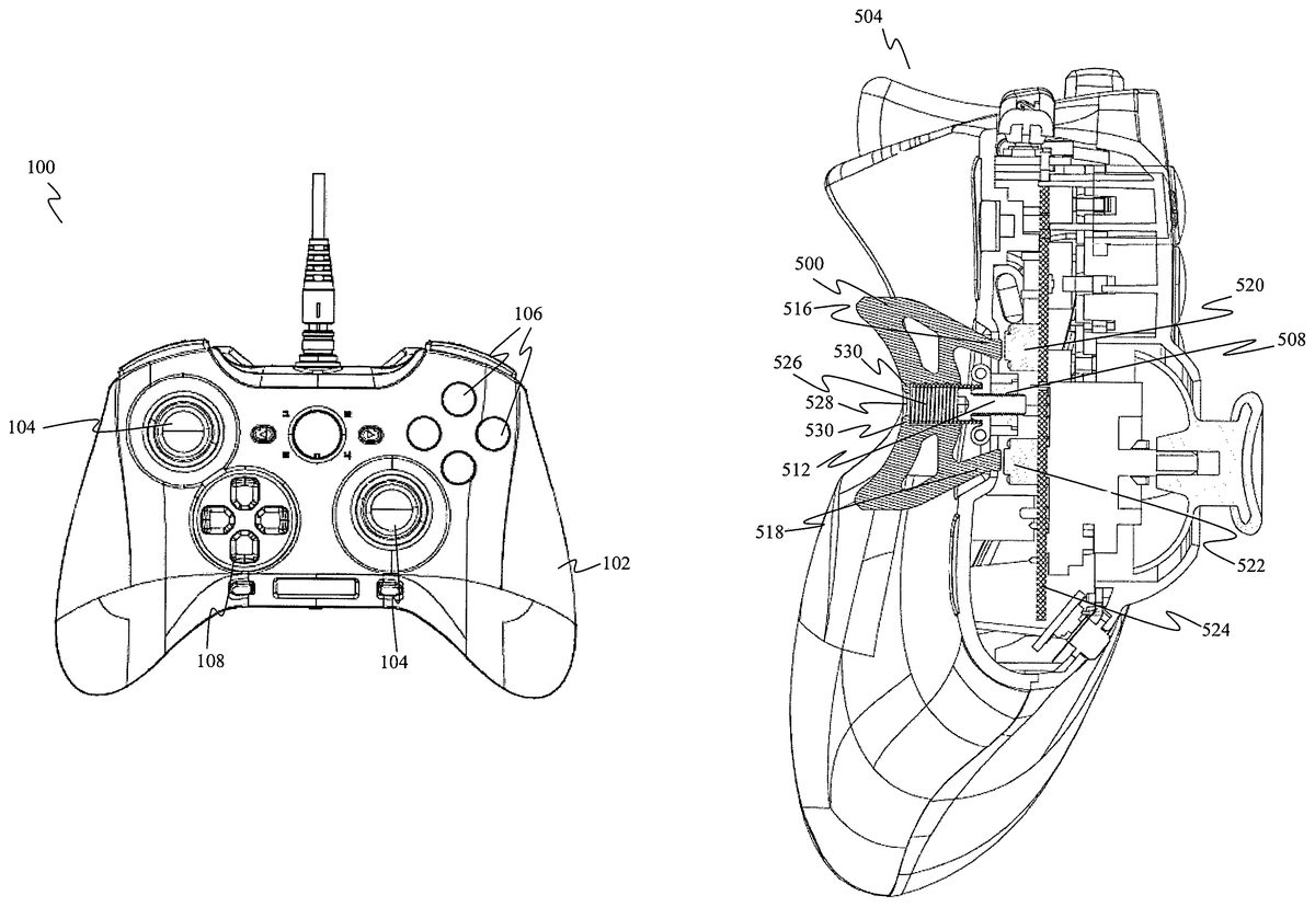
In an example, levers500,502, which are detachable from a game controller504, are shown inFIG. 5Aillustrating a perspective view of the game controller504as seen from its top side accommodating a plurality of game controls506, and inFIG. 5Billustrating another perspective view of the game controller504on its underneath (bottom) side having respective recesses508,510to receive the levers500,502. The levers500,502are detachably secured by respective screws512,514. The recesses508,510may be formed on the housing at the underneath side of the game controller504.
For example, each of the levers500,502may be the lever206ofFIG. 2and the game controller504may be the game controller200ofFIG. 2.
To further illustrate,FIG. 5Cshows a cross-sectional view of the lever500secured to the game controller504by the screw512via the respective recess508as an example. The lever500has contact surfaces516,518configured to contact a first switch520and a second switch522, respectively. The first switch520and the second switch522are placed on a printed circuit board524. For example, the first switch520may be the first switch208ofFIG. 2and the second switch522may be the second switch210ofFIG. 2.
In various embodiments, the lever206may further include a biasing means configured to provide a biasing force to the lever206. For example, the “biasing means” may be made of a resilient material. The biasing means may be but is not limited to a spring. For example, inFIG. 5C, the biasing means or spring526may be arranged between the screw512(i.e., the securing means) and the lever500. The spring526may have a diameter equal to or smaller than the head of the screw512which is in contact with the spring526. When the lever500is secured to the game controller504, the spring526is compressed; thereby providing a cushioning effect between the screw512and the lever500. When the lever500is detached from the game controller504, the spring526is extended to provide a pushing force to more easily separate the lever500from the game controller504.
To detachably secure the lever500to the game controller504, the lever500may have an orifice528which allows a screwdriver to access the head of the screw512so that a user may fasten the screw512to the recess508using the screwdriver. The spring526and the head of the screw512may be held in place in the orifice528by a tapered edge530of the orifice528. In some example, the spring526may have a smaller diameter than that of the head of the screw512. The description above may be similarly applicable to the lever502having its respective screw514securable to its respective recess510.
In various embodiments, the game controller200may further include a bracket configured to hold the securing means to the lever206. In this embodiment, the lever206may be configured to pivot about the bracket to the first position and the second position.
FIG. 6Ashows a plan view of an exemplary game controller600according to various embodiments. The game controller600may refer to the game controller200ofFIG. 2.FIGS. 6B and 6Crespectively show a side view and an end view of the exemplary game controller600ofFIG. 6A.
InFIGS. 6A to 6C, the levers602,604located at the underside (or bottom) of the game controller600(or gamepad) are capable of being triggered using the middle finger of a user by using either a pulling action, a flicking action or a pushing action. A plurality of game controls610(FIG. 6B) are located on the upper side of the game controller600and are capable of being triggered using the user's thumb or index finger. For example, the levers602,604may be referred to the lever206ofFIG. 2, or the lever300ofFIGS. 3A to 3C, or the lever406ofFIG. 4, or the levers500,502ofFIG. 5A.FIGS. 3A to 3C, 4 and 5Cprovide respective cross-sectional views of the lever seen from the dotted line6000ofFIG. 6A. In an example, the plurality of game controls610may be referred to the plurality of game controls204ofFIG. 2.
In another aspect, a lever assembly700for a game controller is provided as shown inFIG. 7. InFIG. 7, the lever assembly700may include a lever702configured to pivot between a neutral position in which the lever702returns when no force is applied thereon, a first position in which the lever702moves when a force is applied on one end of the lever702and a second position in which the lever702moves when another force is applied to another end of the lever702; a securing means704configured to detachably secure the lever702to a game controller; and a bracket706configured to hold the securing means704to the lever702.
In various embodiment, the lever assembly700may further include a biasing means configured to provide a biasing force to the lever702.
The terms “lever”, “game controller”, “side”, “activated”, “switch”, “securing means”, and “biasing means” may be as defined above.
For example, the lever702may be the lever206ofFIG. 2, or the lever300ofFIGS. 3A to 3C, or the lever406ofFIG. 4, or the levers500,502ofFIG. 5A, or the levers602,604ofFIG. 6. The securing means704may be the respective screws512,514ofFIG. 5Aand the biasing means may be the spring526ofFIG. 5C.
InFIGS. 8A to 8I, various views of an exemplary lever assembly800(e.g., may be the lever assembly700ofFIG. 7) are shown.FIGS. 8A and 8Brespectively show a perspective view and an exploded view of the lever assembly800including a lever802, a securing means804, a biasing means806arranged between the lever802and the securing means804, and a bracket808configured to hold the securing means804to the lever802. The lever802may be pivotable about the bracket808. In other words, the bracket808may act as a fulcrum (or pivot) support means for the lever802. The bracket808may be securable to a game controller (not shown inFIGS. 8A and 8B) by the securing means804.
As can be seen inFIG. 8B, the securing means804includes a head812having a diameter that is larger than or similar to the diameter of the biasing means806, more specifically, the inner diameter of the biasing means806. This is to allow the head812to contact or anchor against an end of the biasing means806such that the biasing force may be exerted by the biasing means806based on a securing action or a unsecuring (detaching) action of the securing means to a game controller (not shown inFIG. 8B).
The biasing means806and the securing means804are disposed within an orifice810formed in the lever802. For example, the orifice810may be the orifice528ofFIG. 5C. The biasing means806and the head812of the securing means804may be held in place in the orifice810by a tapered edge of the orifice810. In one non-limiting example, the biasing means806may have a smaller diameter than that of the head812of the securing means804. As a result, the larger head812may function as a blocking mechanism to prevent the securing means804from being displaced through the orifice810. However, it should be appreciated that in an alternative non-limiting example, the head812of the securing means804may have a smaller diameter than the diameter of the biasing means806, or more specifically, the inner diameter of the biasing means806. In this example, it may be possible to prevent the securing means804from being displaced through the orifice810by having the tapered edge of the orifice810functioning as the block mechanism.
In cross-sectional plan and side views of the lever assembly800ofFIGS. 8C and 8Das seen from dotted lines A-A′ and B-B′ ofFIG. 8A, respectively, one end of the biasing means806is abutting the bracket808while another end of the biasing means806is abutting the lever802toward the narrowed or tapered edge of the orifice810. This narrowed or tapered edge may appear as or may be represented by protrusions814of the lever802as seen inFIGS. 8C and 8D. Similarly to the levers500,502ofFIG. 5A, to detachably secure the lever802to the game controller, a screwdriver may be allowed to access the head812of the securing means804via the orifice810of the lever802such that a user may fasten the securing means804to a recess of the housing of the game controller (not shown inFIG. 8) using the screwdriver. Upon securing the lever assembly800to the game controller, contact surfaces820of the lever802may be configured to contact the first switch and the second switch of the game controller respectively. For example, the first switch may be the first switch520and the second switch may be the second switch522ofFIG. 5C.
The bracket808may act as a clamp to secure the securing means804to the lever802. The bracket808includes fasteners816to hold in a clamped configuration as shown in a perspective bottom view of the level assembly800inFIG. 8E. The fasteners816may be but are not limited to rivets (also seen inFIG. 8B). The lever802may be pivotable about the bracket808. For example, the bracket808may provide a fulcrum (or pivot) support means for the lever802.
Such an arrangement of the lever assembly800allows the biasing means806and the securing means804to be arranged to the lever802.
The lever802may be configured to pivot about the bracket808to the first position and the second position. For example, inFIG. 8B, extensions818from the bracket808may be received by respective cavities822of the lever802. The lever802may rotate about these extensions818to a neutral position, the first position and the second position. In a different example, the extensions may be provided on the lever while the cavities receiving these extensions may be located on the bracket. It should be understood and appreciated that the extensions and the receiving cavities may be formed on the lever and the bracket in any configuration as long as the lever may be adapted to pivot about the bracket.
FIGS. 8F to 8Irespectively show a bottom view, a top view, a plan view and a side view of the lever assembly800as seen from directions denoted by respective arrows8000,8002,8004,8006inFIG. 8E.
For example, the lever802may be the lever206ofFIG. 2, or the lever300ofFIGS. 3A to 3C, or the lever406ofFIG. 4, or the levers500,502ofFIG. 5A, or the levers602,604ofFIG. 6or the lever702ofFIG. 7. The securing means804may be the securing means704ofFIG. 7, or the respective screws512,514ofFIG. 5A; and the biasing means806may be the spring526ofFIG. 5C.
In the context of various embodiments, the term “about” as applied to a numeric value encompasses the exact value and a variance of +/−5% of the value.
While the invention has been particularly shown and described with reference to specific embodiments, it should be understood by those skilled in the art that various changes in form and detail may be made therein without departing from the spirit and scope of the invention as defined by the appended claims. The scope of the invention is thus indicated by the appended claims and all changes which come within the meaning and range of equivalency of the claims are therefore intended to be embraced.
Claims
- A game controller comprising: a housing;a plurality of game controls disposed on a first side of the housing;a lever comprising an orifice with a tapered edge;a first switch configured to contact a first end region of the lever;a second switch configured to contact a second end region of the lever;a bracket configured to pivotably engage the lever;a biasing means configured to provide a biasing force to the lever, the biasing means disposed within the orifice, wherein a first end of the biasing means abuts the bracket and a second end of the biasing means abuts the tapered edge;and a securing means anchoring against the biasing means, the securing means fastenable via the orifice to detachably secure the lever to a second side of the housing;wherein the lever is configured to pivot about the bracket, to a neutral position when no force is applied thereon, wherein the lever is configured to pivot to a position, the position being one of a first position in which the first end region contacts the first switch to activate the first switch, or a second position in which the second end region contacts the second switch to activate the second switch, wherein the position depends on a force applied on the lever.
- The game controller of claim 1 , wherein the first side of the housing is an upper side of the housing and the second side of the housing is an underside of the housing.
- The game controller of claim 1 , wherein the lever is configured to pivot from the first position to the second position via the neutral position.
- The game controller of claim 1 , wherein the first switch is activated when a force into the direction of the first switch is applied to the lever.
- The game controller of claim 1 , wherein the lever is configured to pivot about a pivot point to the first position or the second position by exerting a pulling force or a flicking force or a pushing force on the lever into the direction of the first switch and the direction of the second switch, respectively, wherein the pulling force is a force exerted in an opposite direction to the flicking force.
- The game controller of claim 1 , wherein the second switch is deactivated when the lever is in the first position.
- The game controller of claim 1 , wherein the first switch is deactivated when the lever is in the second position.
- The game controller of claim 1 , wherein the lever is configured to pivot about a pivot point to the first position in which the first switch is activated to send a first signal indicating that the first gaming function is to be executed;and wherein the lever is configured to pivot about the pivot point to the second position in which the second switch is activated to send a second signal indicating that the second gaming function is to be executed.
- The game controller of claim 8 , wherein irrespective of the lever being configured to pivot about the pivot point to the first or second position, the first signal is the same as the second signal.
- The game controller of claim 8 , wherein the first signal is different from the second signal.
- The game controller of claim 1 , wherein the plurality of game controls comprises at least one of a pushbutton, a joystick or a directional pad.
- The game controller of claim 1 , wherein the plurality of game controls and the lever are configured to be actuated to send a plurality of signals indicating that a plurality of gaming functions is to be executed.
- The game controller of claim 1 , wherein the plurality of game controls are configured to be actuated to send a plurality of signals indicating that a plurality of gaming functions is to be executed;and wherein the lever is configured to pivot about a pivot point to the first position in which the first switch is activated or the second position in which the second switch is activated to send another signal indicating that at least part of the plurality of gaming functions is to be executed.
- The game controller of claim 1 , wherein the plurality of game controls are configured to be actuated to send a plurality of signals indicating that a plurality of gaming functions is to be executed;and wherein the lever is configured to pivot about a pivot point to the first position in which the first switch is activated or the second position in which the second switch is activated to send another signal indicating that another gaming function different from the plurality of gaming functions is to be executed.
- The game controller of claim 1 , wherein the game controller further comprises a pair of handles.
- The game controller of claim 15 , wherein the lever has a concave part such that the lever can be pivoted about a pivot point to the first position by pressing the first end region of the lever and to the second position by pressing the second end region of the lever, wherein the concave part is the recessed portion.
- The game controller of claim 1 , wherein the lever is disposed at a centre region of the second side of the housing.
- The game controller of claim 1 , wherein the housing is configured to hold a switch assembly comprising the lever, the first switch and the second switch.
- The game controller of claim 1 , further comprising a cover configured to hold parts of the game controller within the housing.
- The game controller of claim 1 , wherein the lever is detachable from the second side of the housing.
Disclaimer: Data collected from the USPTO and may be malformed, incomplete, and/or otherwise inaccurate.