U.S. Pat. No. 9,636,577
TRIGGER ATTACHMENT AND METHOD FOR VIDEOGAME CONTROLLERS
Issue DateJuly 18, 2016
Illustrative Figure
Abstract
A trigger attachment for a game controller having a housing, a trigger extending through the housing with an exposed contact surface and operable through a trigger range of motion between a zero position and an end position, and an additional button spaced from the trigger by a housing spacer. The trigger attachment has an attachment body defining a recess with a receiving face shaped to mate with the finger contact surface of the trigger, a sloped outer front surface, an upper surface, and a lower housing contact surface. The attachment body is sized and shaped to be mounted on the trigger with the trigger's receiving face against the finger contact surface. When mounted on the trigger, the lower housing contact surface is positioned to abut the housing when the trigger is pressed to reduce the trigger range of motion by preventing the trigger from fully achieving the end position.
Description
DETAILED DESCRIPTION Embodiments of the present invention are illustrated inFIGS. 3-21. Referring toFIGS. 3-5, a left and front perspective view, a side view, and a right and rear perspective view, respectively, illustrate one embodiment of a trigger attachment100. Trigger attachment100has an attachment body110sized and shaped to be mounted on a trigger15. Attachment body110has an upper limb104and a lower limb106that each extend from an attachment tip116. In doing so, attachment body110defines a rear-facing (i.e., away from tip116) recess112sized and shaped to mate with trigger15of a controller10. Upper limb104and lower limb106define recess112with an acute angle108to receive trigger tip27therein with an inside surface or receiving face114of recess112abutting finger contact surface25of trigger15. In some embodiments, attachment body110is retained on trigger15by frictional engagement or interference fit with trigger15. To facilitate the frictional engagement, some embodiments of trigger attachment100are made of resilient materials, such as silicone rubber, foam, or the like. Attachment body also defines an outside surface115that extends along a sloped outer front surface118, around attachment tip116, and along a bottom surface120. In some embodiments as shown inFIG. 4, a thickness T of attachment body110from receiving face114to outside surface115is non-uniform. For example, thickness T is greater towards attachment tip116. Optionally, sloped outer front surface118forms a concave slope as it extends towards attachment tip116and has a convex cross section as it extends laterally from edge to edge. These features result in a contoured trigger attachment100that provides increased trigger surface area. One benefit of such a contour is that the resting position of a finger on the sloped outer front surface118is ergonomic and comfortable. Additionally, the user's finger is held in place on sloped outer front surface118with little effort. Such a contour also provides a greater surface area and therefore an increased directional range of finger movement that provides quicker activation of trigger15. Pressure from the user's ...
DETAILED DESCRIPTION
Embodiments of the present invention are illustrated inFIGS. 3-21. Referring toFIGS. 3-5, a left and front perspective view, a side view, and a right and rear perspective view, respectively, illustrate one embodiment of a trigger attachment100. Trigger attachment100has an attachment body110sized and shaped to be mounted on a trigger15. Attachment body110has an upper limb104and a lower limb106that each extend from an attachment tip116. In doing so, attachment body110defines a rear-facing (i.e., away from tip116) recess112sized and shaped to mate with trigger15of a controller10. Upper limb104and lower limb106define recess112with an acute angle108to receive trigger tip27therein with an inside surface or receiving face114of recess112abutting finger contact surface25of trigger15. In some embodiments, attachment body110is retained on trigger15by frictional engagement or interference fit with trigger15. To facilitate the frictional engagement, some embodiments of trigger attachment100are made of resilient materials, such as silicone rubber, foam, or the like. Attachment body also defines an outside surface115that extends along a sloped outer front surface118, around attachment tip116, and along a bottom surface120.
In some embodiments as shown inFIG. 4, a thickness T of attachment body110from receiving face114to outside surface115is non-uniform. For example, thickness T is greater towards attachment tip116. Optionally, sloped outer front surface118forms a concave slope as it extends towards attachment tip116and has a convex cross section as it extends laterally from edge to edge. These features result in a contoured trigger attachment100that provides increased trigger surface area. One benefit of such a contour is that the resting position of a finger on the sloped outer front surface118is ergonomic and comfortable. Additionally, the user's finger is held in place on sloped outer front surface118with little effort. Such a contour also provides a greater surface area and therefore an increased directional range of finger movement that provides quicker activation of trigger15. Pressure from the user's finger in a direction generally perpendicular to any one of various locations on sloped outer front surface118results in movement of the trigger15through the take-up23and towards the active zone21. Additionally, the curved contour of trigger attachment100is aesthetically pleasing.
Lower limb106extends to terminate at a lower housing contact surface122generally facing in a rearward direction or away from attachment tip116. When trigger tip27is received in recess112, lower housing contact surface120is positioned to abut controller housing13to restrict trigger movement when the trigger is activated. As such, lower housing contact surface120reduces the trigger range of motion20. More particularly, lower housing contact surface120is positioned to reduce over travel24of trigger15beyond the active zone21by stopping trigger15prior to reaching end position19.
Optionally, upper limb104extends to define an upper housing contact surface126that is positioned to contact controller housing113when trigger15returns towards the zero position18. By restricting movement of trigger15as it pivots towards zero position18, upper housing contact surface126reduces take-up23or “dead zone” at the beginning of a trigger pull. As a result, the take-up23of trigger15is reduced. In one embodiment, upper limb104wedges between trigger15and housing13when trigger15returns towards zero position18, where upper housing contact surface126is a top surface that contacts housing13. Thus, upper limb104acts as a wedge129to prevent trigger15from returning fully to the zero position18. Other embodiments of wedge member129are discussed below with reference toFIG. 11.
In other embodiments, upper housing contact surface126is a rear-facing surface (i.e., facing away from attachment tip116and towards controller10). Similar to lower housing contact surface122, rear-facing upper housing contact surface126is positioned to abut controller housing13to reduce the trigger range of motion20. For example, upper housing contact surface126abuts housing13as trigger returns towards the zero position, thereby restricting trigger movement and reducing the trigger range of motion20.
In some embodiments, upper limb104defines an upper catch128with an upper catch surface128afacing generally towards lower limb106. Upper catch128is useful to engage an edge or recess along top15aof trigger15. When upper limb104extends to act as a wedge129, upper catch128may engage a groove in trigger15to help maintain the position of wedge129as trigger15pivots.
In some embodiments, lower limb106additionally defines a lower catch124to engage a rear edge15b(shown inFIG. 1B), catch surface, or other feature defined on some embodiments of trigger15. Lower catch124has a lower catch surface124athat faces generally towards upper limb104. Lower catch124extends fully or partially across the width W of trigger attachment100. In some embodiments, lower catch124is a narrow tab or extension from lower limb106that is sized to engage the edge or catch surface on trigger15. For example, lower catch124is a relatively narrow strip of material with lower catch surface124athat extends into housing13to hook a rear edge of trigger15, where lower catch124does not interfere with actuation of trigger15. By extending along the bottom surface of trigger15, lower catch124in some embodiments helps align trigger attachment100on trigger15.
Trigger attachment100prevents movement of trigger15through the full trigger range of motion20by contacting housing13of controller10to reduce take-up23and/or over travel24. Trigger attachment100is dimensioned to reduce the range of trigger travel20while permitting the user to execute the intended function of the trigger15without excessive movement outside of the active zone21. Embodiments of trigger attachment100are dimensioned to define various corresponding trigger ranges of motion20that accommodate a wide variety of videogame controllers10and active zones21of different sizes. For example, lower limb106in some embodiments of trigger attachment100extends rearwardly in different amounts. The length of lower limb106from inside surface116a of attachment tip116defines the point within trigger range of motion20where lower housing contact surface122makes contact with housing13. Thus, for example, the user may own several sets of trigger attachments100where each set is sized for short, medium, or long trigger range of motion20. When switching between games that require different trigger ranges of motion20, the user then may switch trigger attachments100as needed to provide the appropriate range of motion20.
In some embodiments, upper limb104is configured to include a wedge129that fits between housing13and trigger15. Wedge129may be part of upper limb104that defines upper housing contact surface126. Alternately, wedge129is distinct and separate from attachment body110. In such an embodiment, wedge129may be secured permanently or temporarily to trigger top15awith adhesives, mechanical fasteners, snap-lock features, or the like. Wedge129reduces take-up23without diminishing the ability of trigger15to initiate and carry out commands. As with lower housing contact surface122, wedge129or upper housing contact surface126may be dimensioned to reduce take-up23in various amounts to accommodate different trigger designs of different controllers10. In some embodiments, wedge129is part of upper limb104and includes upper catch128and upper housing contact surface126as different faces of wedge129.
Referring toFIG. 5, some embodiments of trigger attachment100include optional adhesive134disposed on all or part of receiving face114for the purpose of fixing trigger attachment100to trigger15. Adhesive134binds trigger attachment100to trigger15with sufficient strength to endure many repeated cycles of user manipulation. In some embodiments, the user applies adhesive134to trigger attachment100just prior to installation on trigger15. In other embodiments, trigger attachment100includes adhesive134already disposed and including a lift-off backing (not shown) that the user removes just prior to installing trigger attachment100on trigger15. In some embodiments, adhesive134is a pressure-sensitive adhesive that is activated when the user applies sufficient pressure. Other variations on adhesive134known in the art are also acceptable.
Referring now toFIGS. 6-8, a right and front perspective view, a right-side view, and a left and rear perspective view, respectively, illustrate another embodiment of trigger attachment100shaped for a different embodiment of trigger15. As with the embodiment of trigger attachment100shown inFIGS. 3-5, the embodiment shown inFIGS. 6-8has trigger body110with an upper limb104and lower limb106each extending away from attachment tip116. Trigger attachment100defines recess112shaped to receive and mate with trigger15. As shown inFIGS. 6-8, lower housing contact surface122faces rearwardly away from attachment tip116and is positioned to contact housing13when trigger15is pressed by the user. Sloped outer front surface118forms a concave slope as it extends towards attachment tip116and has a domed or convex cross section across the width W of trigger attachment100. Bottom surface120is concave to prevent interference with the user's other fingers when pressing trigger15.
Referring now toFIG. 9, some embodiments of trigger attachment100include a mounting bracket150. Mounting bracket150is used to attach trigger attachment100to trigger15. In one embodiment, mounting bracket150is secured to finger contact surface25of trigger15by adhesive. In one embodiment, mounting bracket150is shaped with overhanging or rounded outer bracket edges152a,152b.Receiving face114of attachment body110has corresponding mating features that mate with and engage outer bracket edges152a,152bin sliding engagement, snap fit, or other engagement to hold attachment body110to mounting bracket150, and therefore to trigger15. Mating bracket150facilitates attachment body110being releasably attached to trigger15and use of interchangeable trigger attachments100. In some embodiments, upper catch128engages upper bracket edge152c.Since trigger tip27is received in recess112, attachment body110may be stretched or deformed slightly during installation so that upper catch128will reach to upper bracket edge152c.Thus, when attachment body110attempts to resume a relaxed state, upper catch128may be at tension while gripping upper bracket edge152cand therefore releasably lock attachment body110to trigger15.
In some embodiments, one or more locking tab is formed on the either the trigger body110or mounting bracket150to engage the other component so as to releasably lock the two components together. For example, tabs with a catch surface similar to upper catch128as shown inFIG. 9are disposed along attachment body110to engage outer bracket edges152a,152b.The snap-fit between trigger body110and mounting bracket150provide one method to secure trigger attachment110to trigger15. Mounting bracket150may alternately be installed on other faces of trigger15, such as a bottom face26, where lower catch124(shown inFIG. 5) engages mounting bracket150.
In some embodiments, mounting bracket150is ferromagnetic or includes a bracket ferromagnetic member154. In such embodiments, attachment body110also includes a body ferromagnetic member156, such as a magnet, positioned to mate with bracket ferromagnetic member154. For example, mounting bracket150with bracket ferromagnetic member154is affixed to trigger15. Attachment body110is then mounted to mounting bracket150, which includes body ferromagnetic member156, such as steel. Attachment body110is therefore retained on trigger15using magnetic attraction between the ferromagnetic members154,156, but may be removed by the user as desired. The magnetic force generated by the ferromagnetic members154,156is sufficient to permit use of the trigger attachment100without the decoupling from trigger15during normal operation and including contact between trigger attachment110and housing13.
Referring now toFIG. 10, a front perspective view illustrates an embodiment of a trigger cover200. Trigger cover200attaches to mounting bracket150(shown inFIG. 9) with a sliding motion in which corresponding features (e.g., mating rails) on the two elements create a releasable, but secure connection. In one embodiment, for example, trigger cover includes one or more catches130along its edges or disposed on receiving face114to engage mounting bracket150. Trigger cover lacks lower housing contact surface122and upper housing contact surface126(shown inFIG. 5). Accordingly, trigger cover200may be interchanged with trigger attachment100to allow full trigger range of motion20. Thus, when used with mounting bracket150, trigger cover200provides an option to achieve full trigger range of motion20without removing mounting bracket150from trigger15. Being interchangeable with trigger attachment100, trigger cover200is desirable when playing videogames that do not benefit from, or are inhibited by, reduced trigger range of motion20. In some videogames, only the left or right trigger may benefit from reduced trigger range of motion. In this scenario the trigger cover200may be used on just the left or right trigger15to create a matching aesthetic and reach while only limiting the movement of either the right or left controller trigger15. Additionally, the trigger cover200may provide added surface area for resting as well as additional directions in which to exert force on trigger15to cause trigger15to initiate a signal.
Optionally, trigger cover200or trigger attachment100includes an alignment/locking tab210. In combination with upper catch128on trigger attachment100or with catches130on trigger cover200, alignment/locking tab mechanically, but releasably locks trigger cover200/trigger attachment100to trigger15to ensure successful depression and return of trigger15towards zero position18. Alignment/locking tab210extends rearwardly from lower limb106of trigger attachment100or from lower end202of trigger cover200. Alignment/locking tab210enters housing13to align and stabilize trigger attachment100/cover200. When the trigger15is pressed by the user, trigger attachment100/cover200is under the most stress and most subject to release from trigger15. Alignment/locking tab210stabilizes trigger attachment100/cover200and prevents its removal from trigger15during game play. In general, alignment/locking tab210is made of a strip of material sufficiently thin to pass between trigger15and housing13without interfering with the trigger movement. In some embodiments, alignment/locking tab210is made of a resilient material that can be stretched to engage rear edge15aof trigger15and pull trigger attachment100towards trigger tip27.
The trigger limiter embodiments disclosed herein may be formed from a wide variety of materials including plastics, metals, and metal alloys.
Referring now toFIGS. 11A-11E, and with continued reference toFIGS. 1-2, an embodiment of trigger15is shown in various positions with and without trigger attachment100. The position of rear edge15bin each figure can be used to identify the difference in the position of trigger15between zero position18and end position19.FIGS. 11A and 11Billustrate side views of trigger15with a section of housing13and without trigger attachment100.FIG. 11Aillustrates trigger15in its normal resting state biased to the zero position18. Contact surface25has a trigger radius of curvature15cand a contact surface length25afrom trigger top15ato trigger tip27.FIG. 11Billustrates trigger15in its fully depressed state or end position19.
FIGS. 11C and 11Dshow trigger15with trigger attachment100installed on trigger15. As shown inFIG. 11C, upper limb104extends along finger contact surface25and extending to occupy the space between top15aof trigger15and housing13. Upper housing contact surface126engages housing13to restrict trigger15from returning fully to the zero position18shown inFIG. 11A, thereby reducing take-up23(shown inFIGS. 1B.)FIG. 11Dillustrates trigger15pivoted towards end point19, but is prevented from fully reaching that position due to lower housing contact surface122contacting housing13.FIG. 11Dillustrates how trigger attachment100reduces the over travel24(shown inFIG. 1B) of trigger15. Also shown in both ofFIGS. 11C and 11D, trigger attachment100includes alignment/locking tab210, which extends from lower limb106into housing13to engage rear edge15bof trigger15. Alignment/locking tab210helps retain trigger attachment100on trigger15.
FIG. 11Dalso illustrates user contact surface length118abetween upper surface105and attachment tip116. User contact surface118also defines an attachment radius of curvature111. Table 1 below shows length corresponding to contact surface length25aof triggers15and user contact surface length118afor trigger attachment100. Table 1 also shows the length and radius corresponding to the trigger radius of curvature15cor attachment radius of curvature111.
TABLE 1Properties of Trigger Attachment and TriggersTrigger 15 forTrigger 15 forTriggerPlaystationXBoxattachment 100Length0.70″0.87″0.94″Radius1.4″2.25″0.75″
In some embodiments, trigger attachment100has a user contact surface length118athat is greater than contact surface length25aof a provided trigger15. That is, trigger attachment100increases the contact surface length25a.Trigger attachment100in some embodiments also has attachment radius of curvature111that is less than trigger radius of curvature15c. In some embodiments, attachment radius of curvature111changes along user contact surface length118a,where attachment radius of curvature111is smaller towards attachment tip116These features allow trigger attachment to be more comfortable for the user by more closely following the curvature around one's finger, which typically has a radius of about 0.25″. Thus, the user can better “hook” trigger attachment100with the finger. An increased user contact surface length118aallows enough space for trigger attachment to attain the reduced attachment radius of curvature111. A trigger may only contact about 15% of the circumferential finger surface. In comparison, trigger attachment100contacts approximately 30-40% of the circumferential finger surface.
FIG. 11Eillustrates trigger15with another embodiment of trigger attachment100and separate wedge129adhered to trigger15. Wedge129fits between top15aof trigger15and housing13to prevent trigger15from returning fully to the zero position18. Thus, trigger15inFIG. 11Eis “primed” with a reduced take-up23compared to trigger15inFIG. 11A, which lacks wedge129.
Referring now toFIG. 12, a perspective view illustrates one embodiment of trigger attachment100installed on trigger15of a controller10such as a controller10sold under the trademark PlayStation®. Lower housing contact surface122is positioned to abut housing13when trigger15is pressed by the user to reduce over travel24(shown inFIG. 1B) of trigger15. Upper catch128engages top15aof trigger15to help retain trigger attachment100on trigger15. Upper housing contact surface126races rearwardly and abuts housing13to reduce the take-up23(shown inFIG. 1B) of trigger15. Sloped outer front surface118provides a comfortable grip to the user with a modified surface position compared to finger contact surface25of trigger15.
Referring now toFIG. 13, a perspective view illustrates one embodiment of trigger attachment100installed on trigger15controller10such as a controller10sold under the trademark Xbox®. Lower housing contact surface122is positioned to abut housing13when trigger15is pressed by the user, thereby reducing the over travel24(shown inFIG. 1B) of trigger15. Here, trigger attachment100does not affect the take-up23of trigger15and instead only affects over travel24. Sloped outer front surface118provides a comfortable grip to the user with a modified surface position compared to finger contact surface25of trigger15.
Referring now toFIG. 14, a portion of controller10is illustrated from a side perspective view with trigger attachment100installed on trigger15. Additional button16is positioned above trigger15. Trigger attachment100remains engaged with trigger15due to a snap fit with voids or recesses (not shown) in trigger15. Sloped outer front surface118provides various directions of engagement indicated by arrows119a,119b,respectively, along which the user may apply force to trigger15via trigger attachment100. For example, by positioning the user's finger300(shown inFIG. 15) closer to upper housing contact surface126(or similar position), the user may pull rearwardly to activate trigger function. In contrast, by positioning the user's finger300closer to attachment tip116, the user may pull down and rearwardly to activate trigger15. Thus, the user may find a direction of engagement119that best suits the user's hand size and hand placement on controller10. When the point of contact between finger300and trigger15changes during a trigger pull, such as when the user rolls the finger300along trigger15, the increased change in direction of engagement119on sloped outer front surface118compared to user contact surface25results in improved trigger responsiveness for the user.
Referring now toFIG. 15, a top view shows a portion of controller10ofFIG. 14, where trigger attachment100is installed on trigger15. An additional button16(shown inFIG. 14) is omitted to more clearly see trigger attachment100and trigger15. Part of trigger15extending into trigger attachment100is shown in broken lines. Trigger attachment100abuts contact surface15and wraps around trigger sides15c,15d.In cases where trigger15defines a void14, trigger attachment100preferably occupies void14to further secure trigger attachment100on trigger15. A user's finger300is positioned on sloped outer front surface118of trigger attachment100to actuate the trigger function.
Referring now toFIG. 16, controller10ofFIG. 14is shown in a bottom and side perspective view. Trigger15is visible behind trigger attachment100and below additional button16. Due to the curvature of sloped outer front surface118, user's finger300is at rest against sloped outer front surface118in a more ergonomic position. This ergonomic position allows for a more relaxed finger position on trigger15.
Referring now toFIG. 17, a bottom view of controller10ofFIG. 14shows trigger attachment100installed on trigger15. Lower housing contact surface122extends rearwardly from lower limb106towards housing13to reduce over travel24of trigger15.
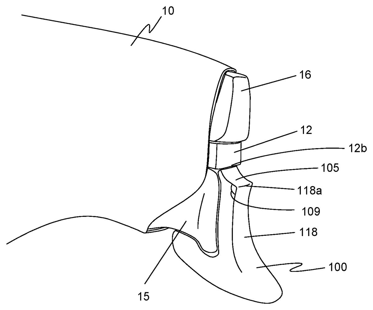
Referring now toFIGS. 18 and 19, a portion of controller10is illustrated from a side perspective view with additional embodiments of trigger attachment100installed on trigger15. Controller10includes additional button16positioned above trigger15and spaced from trigger15by a housing spacer12. Upper surface105extends transversely from a top margin118aof sloped outer front surface118towards a lower margin12aof housing spacer12. In some embodiments, such as shown inFIG. 18, upper surface105is sloped and defines an angle109of about 90-100° from top margin118a.Upper surface105extends at least 2.5 mm towards housing spacer112. In other embodiments, upper surface105extends 3 mm, 4 mm or more from top margin118atowards lower margin12b.
In other embodiments as shown, for example, inFIG. 19, upper surface105is concave and curves upward from top margin118aof sloped outer front surface118to lower margin12bof housing spacer12. In some embodiments, upper surface105has a radius of curvature of three mm to about eight mm, such range of radii corresponding to the typical radius curvature of a human index fingertip302(shown inFIGS. 20-21). When upper surface105is curved, angle109is typically obtuse, such as about 120°.
As shown inFIGS. 20-21, upper surface105may be used for pressing trigger15. Upper surface105provides an alternative to sloped outer front surface118using any one of the directions of engagement119discussed above. In game play, for example, the user may position the finger300on housing spacer12between trigger attachment100and additional button16for rapid toggling between trigger15and additional button16. In this position, applying downward pressure to upper surface105presses trigger15. When more repetitive use of trigger15is required, the user may easily move finger300to sloped outer front surface118of trigger attachment100and use a downward or pulling motion to press trigger15. As shown inFIG. 20, upper surface105being sloped or slightly convex provides a shelf for fingertip302with faster transitioning to sloped outer front surface118. In contrast, curved upper surface of FIG.21better matches the natural curvature of fingertip302for improved grip between fingertip302and upper surface105.
Users of trigger attachment100benefit by reducing unwanted motion in the trigger range of motion20. Other benefits of embodiments of trigger attachment100include improved comfort and ergonomics for actuating trigger15. Depending on the embodiment, trigger attachment100may reduce the over travel24, take-up23, or both. For games where only one trigger15benefits from reduced trigger range of motion20, trigger cover200may be used to provide the same reach and feel for right and left triggers15. Alternately, trigger cover200may be used interchangeably with trigger attachment100when no reduction in trigger range of motion20is desired or necessary.
Although exemplary embodiments of the present invention have been described herein, the above description is merely illustrative. Further modification of the invention herein disclosed will occur to those skilled in the respective arts and all such modifications are deemed to be within the scope of the invention as defined by the appended claims.
Claims
- A trigger attachment for use with a game controller having a housing, a trigger extending through the housing with a finger contact surface and operable through a trigger range of motion between a zero position and an end position, and a button extending through the housing above the trigger and spaced from the trigger by a housing spacer, the trigger attachment comprising: an attachment body defining a recess with a receiving face shaped to mate with the finger contact surface of the trigger, a sloped outer front surface, a lower housing contact surface, and an upper contact surface extending transversely from a top margin of the sloped outer front surface at least 2.5 mm toward a lower margin of the housing spacer, wherein the upper contact surface provides an alternate surface to the sloped outer front surface for an user to press the trigger;wherein the attachment body is sized and shaped to be mounted on the trigger with the trigger partially received in the recess with the finger contact surface of the trigger against the receiving face of the attachment body;and wherein when mounted on the trigger, the lower housing contact surface is positioned to abut the housing when the trigger is pressed, thereby reducing the trigger range of motion by preventing the trigger from fully achieving the end position.
- The trigger attachment of claim 1 , wherein the upper contact surface slopes upward from the upper margin of the sloped outer front surface to the lower margin of the housing spacer.
- The trigger attachment of claim 1 , wherein the upper contact surface curves upward from the upper margin of the sloped outer front surface to the lower margin of the housing spacer.
- The trigger attachment of claim 3 , wherein the upper contact surface has a radius of curvature from 3 mm to 8 mm.
- The trigger attachment of claim 1 further comprising an adhesive disposed on the receiving face of the trigger attachment.
- The trigger attachment of claim 1 , wherein the upper contact surface extends transversely from a top margin of the sloped outer front surface at least 3 mm toward a lower margin of the housing spacer.
- The trigger attachment of claim 1 , wherein the upper contact surface extends transversely from a top margin of the sloped outer front surface at least 4 mm toward a lower margin of the housing spacer.
Disclaimer: Data collected from the USPTO and may be malformed, incomplete, and/or otherwise inaccurate.