U.S. Pat. No. 9,612,737
DEVICE AND METHOD FOR PROCESSING VIRTUAL WORLDS
AssigneeSamsung Electronics Co., Ltd.
Issue DateDecember 18, 2012
Illustrative Figure
Abstract
A device and method for processing virtual worlds. According to embodiments of the present disclosure, information which is measured from the real world using characteristics of a sensor is transferred to a virtual world, to thereby implement an interaction between the real world and the virtual world. The disclosed device and method for processing virtual worlds involve selectively transferring information, from among the measured information, which is different from previously measured information. The disclosed device and method for processing virtual worlds involve transferring the entire measured information in the event that the measured information is significantly different from the previously measured information and for selectively transferring information, from among the measured information, which is different from the measured information in the event that the difference is not significant.
Description
DETAILED DESCRIPTION Reference will now be made in detail to example embodiments, examples of which are illustrated in the accompanying drawings, wherein like reference numerals refer to the like elements throughout. Example embodiments are described below in order to explain example embodiments by referring to the figures. A term ‘object’ used herein may include an object, a thing, an avatar, and the like, implemented and expressed in a virtual world. In addition, a term ‘form’ used herein may be interchangeable with a term ‘type’. Hereinafter, the example embodiments will be described with reference to the accompanying drawings. FIG. 1illustrates an operation of manipulating an object of a virtual world, using a sensor in the real world, according to example embodiments. Referring toFIG. 1, a user110of a real world may manipulate an object120of the virtual world using a sensor100in the real world. The user110may input his or her motion, state, intention, shape, and the like, through the sensor100by performing various movements with the sensor, for example. The sensor100may transmit control information (CI) related to the sensed motion, state, intention, shape, and the like, of the user110, the CI included in a sensor signal, to a virtual world processing apparatus. Depending on embodiments, the user110of the real world may include humans, animals, plants, inanimate objects, such as, articles, and even surrounding environment of the user110. FIG. 2illustrates a system for manipulating an object of a virtual world using a sensor of the real world, according to example embodiments. Referring toFIG. 2, the signal that includes CI201related to the motion, state, intention, shape, and the like, of a user of a real world210(the CI201input through a sensor as a real world device) may be transmitted to a virtual world processing apparatus. Depending on embodiments, the CI201related to the motion, state, intention, shape, and ...
DETAILED DESCRIPTION
Reference will now be made in detail to example embodiments, examples of which are illustrated in the accompanying drawings, wherein like reference numerals refer to the like elements throughout. Example embodiments are described below in order to explain example embodiments by referring to the figures.
A term ‘object’ used herein may include an object, a thing, an avatar, and the like, implemented and expressed in a virtual world. In addition, a term ‘form’ used herein may be interchangeable with a term ‘type’.
Hereinafter, the example embodiments will be described with reference to the accompanying drawings.
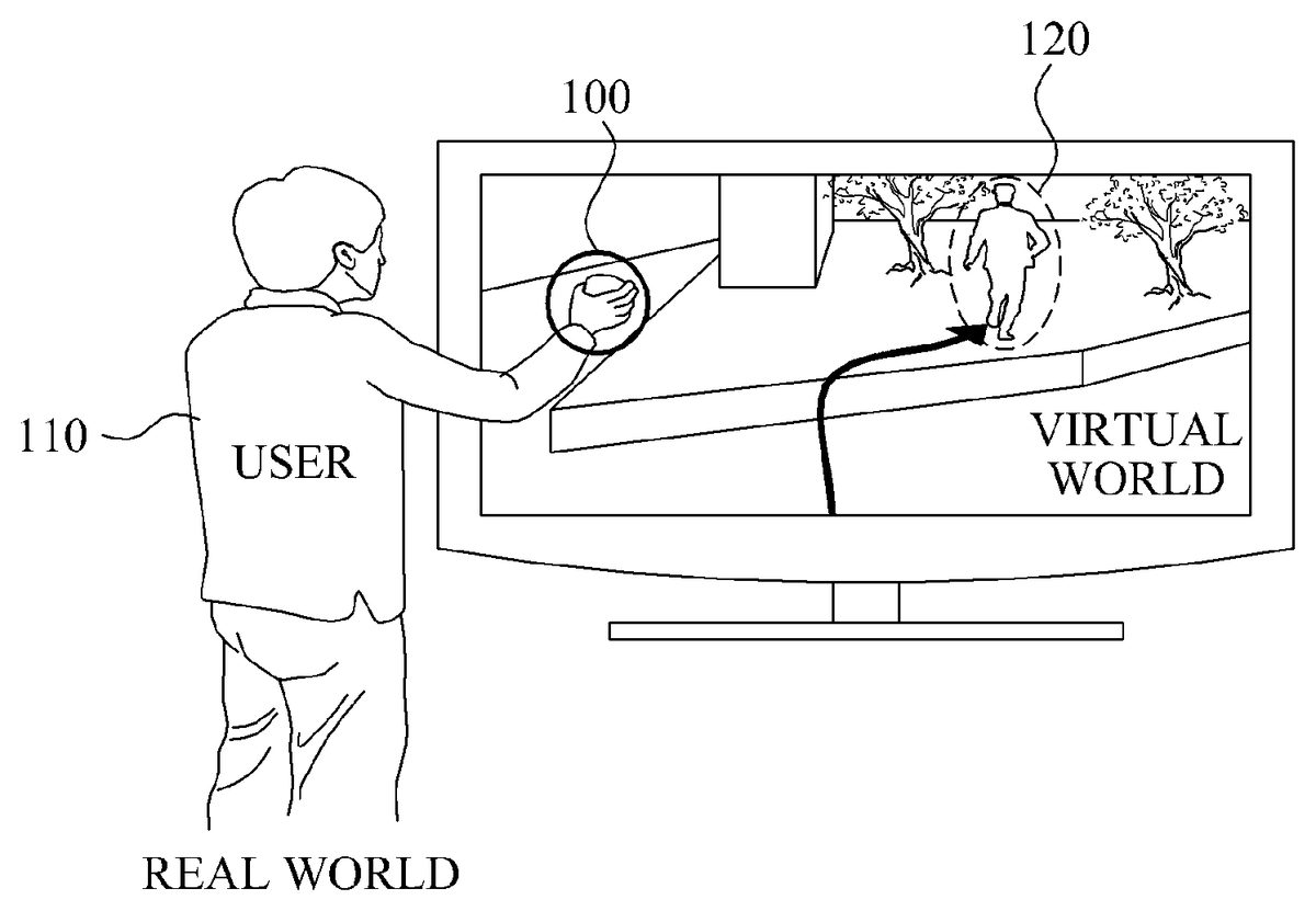
FIG. 1illustrates an operation of manipulating an object of a virtual world, using a sensor in the real world, according to example embodiments.
Referring toFIG. 1, a user110of a real world may manipulate an object120of the virtual world using a sensor100in the real world. The user110may input his or her motion, state, intention, shape, and the like, through the sensor100by performing various movements with the sensor, for example. The sensor100may transmit control information (CI) related to the sensed motion, state, intention, shape, and the like, of the user110, the CI included in a sensor signal, to a virtual world processing apparatus.
Depending on embodiments, the user110of the real world may include humans, animals, plants, inanimate objects, such as, articles, and even surrounding environment of the user110.
FIG. 2illustrates a system for manipulating an object of a virtual world using a sensor of the real world, according to example embodiments.
Referring toFIG. 2, the signal that includes CI201related to the motion, state, intention, shape, and the like, of a user of a real world210(the CI201input through a sensor as a real world device) may be transmitted to a virtual world processing apparatus. Depending on embodiments, the CI201related to the motion, state, intention, shape, and the like, of the user may include a sensor capability, a sensor adaptation preference, and sensed information that is sensed by the sensor in the real world.
The virtual world processing apparatus may include an adaptation real world to virtual world (RV)220. The adaptation RV220may be implemented by an RV engine. The adaptation RV220may convert information of the real world210to information applicable to a virtual world240, using the CI201related to the motion, state, intention, shape, and the like, of the user of the real world210, the CI201included in the sensor signal.
Depending on embodiments, the adaptation RV220may convert virtual world information (VWI)202using the CI201related to the motion, state, intention, shape, and the like, of the user of the real world210.
The VWI202denotes information relating to the virtual world240. For example, the VWI202may include information on an object of the virtual world240or elements constituting the object.
The virtual world processing apparatus may transmit converted information203converted by the adaptation RV220to the virtual world240through adaptation real world to virtual world/virtual world to real world (RV/VR)230.
Table 1 describes structures illustrated inFIG. 2.
TABLE 1NameDescriptionSIDCSensory input device capabilitiesAnother expression of sensor capabilityVWIVirtual world informationUSIPUser sensory input preferencesAnother expression of sensor adaptation preferenceSODCSensory output device capabilitiesSIDCmdSensory input device commandsUSOPUser sensory output preferencesVWCVirtual world capabilitiesSODCmdSensory output device commandsVWPVirtual world preferencesSEMSensory effect metadataVWEMVirtual world effect metadataSISensory information
FIG. 3illustrates a virtual world processing apparatus for manipulating an object of a virtual world using a sensor in the real world, according to other example embodiments.
Referring toFIG. 3, a sensor250may collect information on a motion, state, intention, shape, and the like, of a user of a real world based on the user's manipulation of the sensor250. The information collected by the sensor250may include sensed information sensed by the sensor.
Depending on embodiments, the sensor250may include an input unit. The input unit may be input with a sensor adaptation preference by the user of the real world.
The sensor250may include a metadata encoder251configured to encode the collected information of the sensor250into metadata.
The metadata encoder251may encode the collected information to first metadata. The sensor250may transmit the first metadata to an adaptation RV255. A metadata decoder256included in the adaptation RV255may decode the first metadata received from the sensor250, and then transmit the decoded first metadata to the adaptation RV255.
Depending on embodiments, the metadata encoder251may include at least one of an Extensible Markup Language (XML) encoder that encodes the collected information into XML data and a binary encoder that encodes the collected information into binary data. The metadata decoder256may include at least one of an XML decoder that decodes received XML data and a binary decoder that decodes received binary data.
Hereinafter, encoding of the information collected by the sensor250and decoding of the data received by the adaptation RV255, according to example embodiments will be described with reference toFIGS. 4 to 6.
FIGS. 4 to 6illustrate a sensor and an adaptation RV, according to example embodiments.
Referring toFIG. 4, a sensor271may include an XML encoder272. The XML encoder272may encode information collected by the sensor271, for example sensed information, into data of the XML format.
The sensor271may transmit the data encoded by the XML encoder272to an adaptation RV274.
The adaptation RV274may include an XML decoder273. The XML decoder273may decode the data received from the sensor271.
Referring toFIG. 5, a sensor275according to example embodiments may include an XML encoder276and a binary encoder277. The XML encoder276may encode information collected by the sensor275, for example, sensed information, into data of the XML format. The binary encoder277may encode the data encoded by the XML encoder276into data of the binary form.
In addition, the sensor275may transmit the data encoded by the XML encoder276and the binary encoder277to an adaptation RV280.
The adaptation RV280may include a binary decoder278and an XML decoder279. The binary decoder278may decode the data received from the sensor275into data of the XML format. The XML decoder279may decode the data decoded into the XML format by the binary decoder278.
Referring toFIG. 6, a sensor281according to example embodiments may include a binary encoder282. The binary encoder282may encode information collected by the sensor281, for example sensed information, into data of the binary form.
The sensor281may transmit the data encoded by the binary encoder282to an adaptation RV284unit.
The adaptation RV284unit may include a binary decoder283. The binary decoder283may decode the data received from the sensor281, e.g., sensed information encoded into the binary format.
Referring back toFIG. 3, a metadata decoder258included in the adaptation RV284may decode second metadata received from an adaptation VR260. The second metadata or metadata of the second form may correspond to metadata generated by a metadata encoder262included in the adaptation VR260, by encoding the information on a virtual world265.
Depending on embodiments, the metadata encoder262may include at least one of an XML encoder that encodes the information on the virtual world265into metadata of the XML format and a binary encoder that encodes the information on the virtual world265into metadata of the binary format.
Depending on embodiments, the metadata encoder262may include an XML encoder. The XML encoder may encode the information on the virtual world265into data of the XML format.
In addition, according to other example embodiments, the metadata encoder262may include an XML encoder and a binary encoder. The XML encoder may encode the information on the virtual world265into data of the XML format. The binary encoder may encode the data of the XML format to data of the binary format.
Also, according to other example embodiments, the metadata encoder262may include a binary encoder. The binary encoder may encode the information on the virtual world265into data of the binary form.
The adaptation RV255may generate information to be applied to the virtual world265, based on information decoded from the first metadata by the metadata decoder256and information decoded from the metadata of the second form by the metadata decoder258. Here, the adaptation RV255may generate the information to be applied to the virtual world265, such that the information corresponds to virtual world object characteristics and sensed information included in the metadata of the second form.
A metadata encoder257may encode the information, which is generated by the adaptation RV255, and which is to be applied to the virtual world265, into third metadata. In addition, the adaptation RV255may transmit the third metadata to the adaptation VR260.
A metadata decoder261included in the adaptation VR260may decode the third metadata. The adaptation VR260may convert attributes of an object of the virtual world265based on the decoded information and, in addition, may apply the converted attributes to the virtual world265.
A virtual world processing system may transmit the information on the virtual world265to an actuator of the real world so that the information on the virtual world265is reflected to the real world. Hereinafter, example embodiments in which the information on the virtual world265is reflected to the real world will be described in detail.
FIGS. 7 to 9illustrate an adaptation VR engine and an actuator, according to example embodiments.
Referring toFIG. 7, an adaptation VR engine285may include an XML encoder286. The adaptation VR engine285, as an example embodiment of the adaptation RV255shown inFIG. 3, may transmit the information relating to the virtual world265to an actuator288of a real world so that the information on the virtual world265is reflected to the real world.
The adaptation VR260may collect information relating to a change in attributes of an object of the virtual world265, and transmit the collected information to the adaptation VR engine285. The adaptation VR285may include the XML encoder286. The XML encoder286may encode the information on the virtual world265into data of the XML format. In addition, the adaptation VR engine285may transmit the data encoded by the XML encoder286to the actuator288.
The actuator288may include an XML decoder287. The XML decoder287may decode the XML data received from the adaptation VR engine285.
Accordingly, the actuator288may operate based on the information decoded by the XML decoder287.
Referring toFIG. 8, which illustrates an example embodiment, an adaptation VR engine290may include an XML encoder291and a binary encoder292.
The adaptation VR260may collect information relating to a change in attributes of the object of the virtual world265, and transmit the collected information to the adaptation VR engine290. The adaptation VR engine290may include the XML encoder291and the binary encoder292. The XML encoder291may encode the received information on the virtual world265into data of the XML format. The binary encoder292may encode the data encoded by the XML encoder291to data of the binary format. In addition, the adaptation VR engine290may transmit the data encoded by the XML encoder292to an actuator295.
The actuator295may include a binary decoder293and an XML decoder294. The binary decoder293may decode the binary data received from the adaptation VR engine290into data of the XML format. The XML decoder294may decode the data decoded into the XML format by the binary decoder293.
The actuator295may operate based on the information decoded by the XML decoder294.
Referring toFIG. 9, an adaptation VR engine296may include a binary encoder297.
The adaptation VR260may collect information on a change in attributes of the object of the virtual world265, and transmit the collected information to the adaptation VR engine296. The adaptation VR engine296may include a binary encoder297. The binary encoder297may encode the received information on the virtual world265into data of the binary form. In addition, the adaptation VR engine296may transmit the data encoded by the binary encoder297to an actuator299.
The actuator299may include a binary decoder298. The binary decoder298may decode the binary data received from the adaptation VR engine296.
The actuator299may operate based on the information decoded by the binary decoder298.
FIG. 10is a view illustrating a structure of a virtual world processing apparatus according to example embodiments.
Referring toFIG. 10, a virtual world processing apparatus300includes a storage unit310and a processing unit320.
The storage unit310stores sensor capability related to a sensor.
The sensor may measure a motion, state, intention, shape, and the like of a user of a real world. The sensor may be expressed as a sensory input device. Depending on embodiments, the sensor may be classified according to sensor types including (1) acoustic, sound, and vibration, (2) automotive and transportation, (3) chemical, (4) electric current, electric potential, magnetic, and radio, (5) environment and weather, (6) flow, (7) ionizing radiation, and subatomic particles, (8) navigation instruments, (9) position, angle, displacement, distance, speed, and acceleration, (10) optical, light, and imaging, (11) pressure, force, density, and level, (12) thermal, heat, and temperature, (13) proximity and presence, and (14) sensor technology.
Table 2 illustrates examples sensor according to the sensor types. Therefore, the sensors in Table 2 are suggested only as an embodiment but not limiting.
TABLE 2Sensor typeList of sensors(1) Acoustic, sound,GeophonevibrationHydrophoneLace sensor, a guitar pickupMicrophoneSeismometerAccelerometer(2) Automotive,Crank sensortransportationCurb feelerDefect detectorMap sensorParking sensorsParktronicRadar gunSpeedometerSpeed sensorThrottle position sensorVariable reluctance sensorWheel speed sensor(3) ChemicalBreathalyzerCarbon dioxide sensorCarbon monoxide detectorCatalytic bead sensorChemical field-effect transistorElectronic noseElectrolyte-insulator-semiconductor sensorHydrogen sensorInfrared point sensorIon-selective electrodeNondispersive infrared sensorMicrowave chemistry sensorNitrogen oxide sensorOptodeOxygen sensorPellistorpH glass electrodePotentiometric sensorRedox electrodeSmoke detectorZinc oxide nanorod sensor(4) Electric current, electricAmmeterpotential, magnetic, radioCurrent sensorGalvanometerHall effect sensorHall probeLeaf electroscopeMagnetic anomaly detectorMagnetometerMetal detectorMultimeterOhmmeterVoltmeterWatt-hour meter(5) Environment, weatherFish counterGas detectorHygrometerPyranometerPyrgeometerRain gaugeRain sensorSeismometers(6) FlowAir flow meterFlow sensorGas meterMass flow sensorWater meter(7) Ionizing radiation,Bubble chambersubatomic particlesCloud chamberGeiger counterNeutron detectionParticle detectorScintillation counterScintillatorWire chamber(8) Navigation instrumentsAir speed indicatorAltimeterAttitude indicatorFluxgate compassGyroscopeInertial reference unitMagnetic compassMHD sensorRing laser gyroscopeTurn coordinatorVariometerVibrating structure gyroscopeYaw rate sensor(9) Position, angle,Accelerometerdisplacement, distance,Inclinometerspeed, accelerationLaser rangefinderLinear encoderLinear variable differential transformer (LVDT)Liquid capacitive inclinometersOdometerPiezoelectric accelerometerPosition sensorRotary encoderRotary variable differential transformerSelsynTachometer(10) Optical, light, imagingCharge-coupled deviceColorimeterInfra-red sensorLED as light sensorNichols radiometerFiber optic sensorsPhotodiodePhotomultiplier tubesPhototransistorPhotoelectric sensorPhotoionization detectorPhotomultiplierPhoto resistorPhotoswitchPhototubeProximity sensorScintillometerShack-HartmannWavefront sensor(11) Pressure, force, density,AnemometerlevelBhangmeterBarographBarometerHydrometerLevel sensorLoad cellMagnetic level gaugeOscillating U-tubePressure sensorPiezoelectric sensorPressure gaugeStrain gaugeTorque sensorViscometer(12) Thermal, heat,BolometertemperatureCalorimeterHeat flux sensorInfrared thermometerMicrobolometerMicrowave radiometerNet radiometerResistance temperature detectorResistance thermometerThermistorThermocoupleThermometer(13) Proximity, presenceAlarm sensorBedwetting alarmMotion detectorOccupancy sensorPassive infrared sensorReed switchStud finderTriangulation sensorTouch switchWired glove(14) Sensor technologyActive pixel sensorMachine visionBiochipBiosensorCapacitance probeCatadioptric sensorcarbon paste electrodeDisplacement receiverelectromechanical filmElectro-optical sensorImage sensorInductive sensorIntelligent sensorLab-on-a-chipLeaf sensorRADARSensor arraySensor nodeSoft sensorStaring arrayTransducerUltrasonic sensorVideo sensor
Examples of the sensor types will be described below. The microphone belonging to a sensor type (1), i.e., acoustic, sound, and vibration, may collect voice of the user of the real world and ambient sounds of the user. The speed sensor belonging to the sensor type (2), i.e., automotive and transportation, may measure speed of the user of the real world and speed of an object such as a vehicle of the real world. The oxygen sensor belonging to the sensor type (3), i.e., chemical, may measure an oxygen ratio in ambient air around the user of the real world and an oxygen ratio in liquid around the user of the real world. The metal detector belonging to the sensor type (4), i.e., electric current, electric potential, magnetic, and radio, may detect metallic substances present in or around the user of the real world. The rain sensor belonging to the sensor type (5), i.e., environment and weather, may detect whether it is raining in the real world. The flow sensor belonging to the sensor type (6), i.e., flow, may measure a ratio of a fluid flow of the real world. The scintillator belonging to the sensor type (7), i.e., ionizing radiation and subatomic particles, may measure a ratio or radiation present in or around the user of the real world. The variometer belonging to the sensor type (8), i.e., navigation instruments, may measure a vertical movement speed of or around the user of the real world. The odometer belonging to the sensor type (9), i.e., position, angle, displacement, distance, speed, and acceleration, may measure a traveling distance of an object of the real world, such as a vehicle. The phototransistor belonging to the sensor type (10), i.e., optical, light, and imaging, may measure light of the real world. The barometer belonging to the sensor type (11), i.e., pressure, force, density, and level, may measure an atmospheric pressure of the real world. The bolometer belonging to the sensor type (12), i.e., thermal, heat, and temperature, may measure radiation rays of the real world. The motion detector belonging to the sensor type (13), i.e., proximity and presence, may measure a motion of the user of the real world. The biosensor belonging to the sensor type (14), i.e., sensor technology, may measure biological characteristics of the user of the real world.
FIG. 11illustrates a structure of a virtual world processing apparatus350, according to other example embodiments.
Referring toFIG. 11, an input device360according to the present embodiments may be input with a sensor adaptation preference361by a user of a real world. Depending on embodiments, the input device360may be modularized and inserted in a sensor370or a virtual world processing apparatus350. The sensor adaptation preference361will be described in further detail with reference toFIGS. 7 to 9.
The sensor370may transmit a sensor capability371and sensed information372to the virtual world processing apparatus350.
The virtual world processing apparatus350may include a signal processing unit351and an adaptation unit352.
The signal processing unit351may receive the sensor capability371and the sensed information372from the sensor370, and perform signal-processing with respect to the sensor capability371and the sensed information372. Depending on embodiments, the signal processing unit351may filter and validate the sensor capability371and the sensed information372.
The adaptation unit352may receive the sensor adaptation preference361from the input device360. In addition, based on the received sensor adaptation preference361, the adaptation unit352may perform adaptation with respect to the information signal processed by the signal processing unit351so that the information is applied to a virtual world380. In addition, the virtual world processing apparatus350may apply the information having undergone the adaptation by the adaptation unit352to the virtual world380.
The sensor capability denotes information on capability of a sensor.
A sensor capability base type denotes a base type of the sensor capability. Depending on embodiments, the sensor capability base type may be a base abstract type of the metadata related to a sensor capability that is commonly applied to all types of sensors, as part of metadata types related to the sensor capability.
During the transfer of information between a virtual world and a real world, when current information to be transferred at a predetermined point in time is narrowly different from past information that is previously transferred, only a portion of the current information which differs from the past information may be transferred. Conversely, when the current information is significantly different from the past information, the entire current information may be transferred. The foregoing may be performed to reduce a total amount of information to be transferred between the virtual world and the real world, thereby increasing efficiency.
For example, when a user wears a motion sensor, information on the motion sensor may be transmitted wirelessly. In this instance, unless the user moves, current information on the motion sensor may be narrowly different from past information on the motion sensor. In this instance, when all the current information on the motion sensor is transmitted, all information related to the motion sensor, for every frame, may be transmitted. However, when an update scheme, that is, a scheme of transferring only a different portion between the current information and the past information, is employed, other information apart from a time stamp, among commands related to the motion sensor may not be transferred since the motion sensor does not move. That is, information related to position, orientation, velocity, angular velocity, acceleration, and angular acceleration, for every frame, may not be transmitted. Accordingly, a wireless communication transmission load may be reduced considerably.
In the foregoing embodiments, the binary encoder277ofFIG. 5, the binary encoder282ofFIG. 6, the binary encoder292ofFIG. 8, and the binary encoder297ofFIG. 9may transfer information between a virtual world and a real world to the binary decoder278ofFIG. 5, the binary decoder283ofFIG. 6, the binary decoder293ofFIG. 8, and the binary decoder298ofFIG. 9, respectively.
Each of the binary encoder277, the binary encoder282, the binary encoder292, and the binary encoder297may operate in one of a normal mode and an update mode.
In the normal mode, each of the binary encoder277, the binary encoder282, the binary encoder292, and the binary encoder297may encode and output all received information, regardless of a difference between previously transmitted information.
In an example embodiment, each of the binary encoder277, the binary encoder282, the binary encoder292, and the binary encoder297may output metadata of the binary format that is encoded into first metadata or metadata of a first form, when an operating mode is the normal mode. For example, the first metadata may include items in information or data.
In the update mode, each of the binary encoder277, the binary encoder282, the binary encoder292, and the binary encoder297may encode and output only a portion of information that is currently received, which differs from information that was previously received.
In an example embodiment, each of the binary encoder277, the binary encoder282, the binary encoder292, and the binary encoder297may output metadata of the binary format that is encoded into second metadata or metadata of a second form, when an operating mode is the update mode. For example, the second metadata ay include an item of which a value is different from a previous value of the item, among the items in information or data.
In addition, in the update mode, each of the binary encoder277, the binary encoder282, the binary encoder292, and the binary encoder297may compare the information that is currently received to past information that is previously received. When the currently-received information is significantly different from the past information, each of the binary encoder277, the binary encoder282, the binary encoder292, and the binary encoder297may encode and output the entire currently-received information. Conversely, when the current information is narrowly different from the past information received, each of the binary encoder277, the binary encoder282, the binary encoder292, and the binary encoder297may encode and output the portion of the current information, which differs from the past information.
Each of the binary decoder278, the binary decoder283, the binary decoder293, and the binary decoder298may operate in one of the normal mode and the update mode, as well.
In the normal mode, the binary decoder278, the binary decoder283, the binary decoder293, and the binary decoder298may receive all information from the binary encoder277, the binary encoder282, the binary encoder292, and the binary encoder297, respectively. Accordingly, each of the binary decoder278, the binary decoder283, the binary decoder293, and the binary decoder298may decode and output all of the received information, regardless of a difference between previously received information.
In an example embodiment, each of the binary decoder278, the binary decoder283, the binary decoder293, and the binary decoder298may output metadata of the binary format that is decoded into first metadata or metadata of a first form, when an operating mode is the normal mode. For example, the first metadata may include items in information or data.
In the update mode, the binary decoder278, the binary decoder283, the binary decoder293, and the binary decoder298may receive only a portion of the information currently received which differs from past information, from the binary encoder277, the binary encoder282, the binary encoder292, and the binary encoder297, respectively. In this instance, each of the binary decoder278, the binary decoder283, the binary decoder293, and the binary decoder298may decode and output the received portion of the information. In this instance, another part of the system having received the information according to example embodiment may perform necessary functions, using remaining information from the previously received information.
In an example embodiment, each of the binary decoder278, the binary decoder283, the binary decoder293, and the binary decoder298may output metadata of the binary format that is decoded into second metadata or metadata of a second form, when an operating mode is the update mode. For example, the second metadata ay include an item of which a value is different from a previous value of the item, among the items in information or data.
In addition, each of the binary decoder278, the binary decoder283, the binary decoder293, and the binary decoder298may decode the received portion of the information, and may output the information by incorporating the remaining information from the previously received information into the received portion of the information. In this instance, another part of the system having received the information according to example embodiments may operate transparently with respect to a difference in the information transmitted in the normal mode and the update mode.
Further, as described above, since each of the binary encoder277, the binary encoder282, the binary encoder292, and the binary encoder297may output the entire current information in the update mode as well, each of the binary decoder278, the binary decoder283, the binary decoder293, and the binary decoder298may also decode and output the entire currently-received information in the update mode, e.g., when the currently received information is significantly different from previously received information.
FIG. 12is a view illustrating structures of a binary encoder410and a binary decoder450supporting a normal mode and an update mode, according to example embodiments.
A binary encoder410may include a switch420, a normal mode binary encoding unit430, and an update mode binary encoding unit440.
The switch420may include a plurality of output ports. One of the plurality of output ports may be connected to an input of the normal mode binary encoding unit430, and another of the plurality of output ports may be connected to an input of the update mode binary encoding unit440. The switch420may transmit information input into the binary encoder410, by switching to the normal mode binary encoding unit430or the update mode binary encoding unit440depending on a current operating mode.
The normal mode binary encoding unit430may perform the operation of each of the binary encoder277ofFIG. 5, the binary encoder282ofFIG. 6, the binary encoder292ofFIG. 8, and the binary encoder297ofFIG. 9in the normal mode. That is, the normal mode binary encoding unit430may output the input information encoded in the normal mode. The update mode binary encoding unit440may perform the operation of each of the binary encoder277, the binary encoder282, the binary encoder292, and the binary encoder297in the update mode. That is, the update mode binary encoding unit440may output the input information encoded in the update mode.
A binary decoder450may include a normal mode binary decoding unit460, an update mode binary decoding unit470, and a switch480.
The normal mode binary decoding unit460may perform operations of each of the binary decoder278ofFIG. 5, the binary decoder283ofFIG. 6, the binary decoder293ofFIG. 8, and the binary decoder298ofFIG. 9in the normal mode. That is, the normal mode binary decoding unit460may output the information input from the normal mode binary encoding unit430and decoded in the normal mode, e.g., all of the received information. The update mode binary decoding unit may perform the operations of each of the binary decoder278, the binary decoder283, the binary decoder293, and the binary decoder298in the update mode. That is, the update node binary decoding unit470may output the input information input from the update mode binary encoding unit440and decoded in the update mode.
The switch480may include a plurality of input ports. One of the plurality of input ports may be connected to an output of the normal node binary decoding unit460, and another of the plurality of input ports may be connected to an output of the update mode binary decoding unit470. The switch480may switch to one of the output of the normal mode binary decoding unit460and the output of the update mode binary decoding unit470depending on a current operating mode.
FIG. 13illustrates a structure of information metadata500to be transmitted from the binary encoder277ofFIG. 5, the binary encoder282ofFIG. 6, the binary encoder292ofFIG. 8, the binary encoder297ofFIG. 9, and the binary encoder410ofFIG. 12to the binary decoder278ofFIG. 5, the binary decoder283ofFIG. 6, the binary decoder293ofFIG. 8, the binary decoder298ofFIG. 9, and the binary decoder450ofFIG. 12, respectively, according to example embodiments. The metadata500may correspond to sensor update metadata indicating an update of information collected by a sensor. The metadata500may correspond to sensory update metadata indicating an update of information collected by an apparatus.
The metadata500may include a command type510, an individual type520, an updating mode530, a list update540, a flag field550, and a data field560.
The command type510denotes a type of the metadata500. The command type510may have a fixed length, for example, a 4-bit length.
The individual type520denotes a type of an individual device and a type of a sensor. The individual type520may have a fixed length, for example, a 5-bit length.
The updating mode530denotes modes of the binary encoder277, the binary encoder282, the binary encoder292, the binary encoder297, and the binary encoder410, and modes of the binary decoder278, the binary decoder283, the binary decoder293, the binary decoder298, and the binary decoder450. That is, depending on a value of the updating mode530, the modes of the binary encoder277, the binary encoder282, the binary encoder292, the binary encoder297, and the binary encoder410, and mode of the binary decoder278, the binary decoder283, the binary decoder293, the binary decoder298, and the binary decoder450may be changed. Since the mode corresponds to a normal mode or an update mode, the two different modes may be distinguished using 1-bit information.
The updating mode530may be included as a portion of the command type510. That is, when the command type510has a predetermined value, embodiments may be configured so that the command type510may act as the updating mode530, or embodiments may be configured so that a predetermined bit of the command type510may act as a bit of the updating mode530.
The flag field550denotes flag fields to be included in the metadata500.
The data field560denotes data fields to be included in the metadata500.
Data may be mandatory or optional. In a case of optional data, whether the data is included in metadata is to be indicated. A flag may indicate whether predetermined data is included in metadata. For example, when a value of a flag A corresponds to “1,” data B corresponding to the flag A may be included in metadata C. When the value of the flag A corresponds to “0,” the data B corresponding to the flag A may not be included in the metadata C.
The foregoing may be represented using a binary representation syntax, as shown in Code 1.
[Code 1]C {Aif (A) {B}}
A plurality of data may correspond to the single flag A. For example, when the data B and data C correspond to the flag A of the metadata C, a binary representation syntax may be provided as shown in Code 2.
[Code 2]C {Aif (A) {BC}}
The data B corresponding to the single flag A may include a subfield. The subfield of the data B may also include another subfield.
For example, when the data B corresponds to the flag A of the metadata C, the data B includes a flag D as a subfield, and the flag D corresponds to data E, a binary representation syntax may be provided as shown in Code 3.
[Code 3]C {Aif (A) {B}}B {Dif (D) {E}}
In this example, A and D are to be “1” so that the optional data E may be present.
A plurality of flags having an identical name or a plurality of data having an identical name may be present in the metadata500. In this instance, the plurality of flags or the plurality of data may be present as an array, e.g., an index for specifying an element may be used in the array. In addition, initialization and addition/subtraction operations may be applied to the index.
Code 4 denotes metadata D including a flag array A, data B corresponding to A[0], and data C corresponding to A[1].
[Code 4]D {Aif (A[0]) {B}if (A[1]) {C}}
Code 4 may be represented using a variable E for indexing, as shown in Code 5.
[Code 5]D {AE = 0if (A[E]) {BE++}if (A[E]) {C}}
In Code 5, E is primarily initialized to a value of “0,” and increased by “1” in order to indicate an index 1.
A first normal mode according to example embodiments will be described herein.
A transmission side may transmit metadata including all flags and all mandatory data corresponding to the flags. In a case of optional data, only when a value of a flag corresponding to the optional data corresponds to “1,” may the optional data be included in the metadata and transmitted. A reception side may extract all flags and all mandatory data from received metadata. In a case of optional data, the reception side may verify a value of a flag corresponding to the optional data. Only when the value of the flag corresponding to the optional data corresponds to “1,” may the reception side extract the optional data. A relative priority of a flag, mandatory data, and optional data may be predetermined.
A second normal node according to example embodiments will be described herein.
The transmission side may transmit metadata including all flags, all mandatory data, and all optional data.
Optional data which, in actuality, is nonexistent in view of a value of a corresponding flag may be transmitted while being given a fixed value or a predetermined value. The reception side may identify and discard nonexistent data among all the optional data.
A first update mode according to example embodiments will be described herein.
The transmission side may determine a number of bits of the list update540.
The number of bits may correspond to a sum of a number of all flags and a number of all data. For example, when three flags and four data are provided, the list update540may be configured with 7 bits. Each bit may correspond to the flag or data. In this example, when a flag or data is to be included in metadata at all times, a bit corresponding to the flag or data may be excluded.
When a value of a flag is changed from a previous value, the transmission side may include the flag in the flag field550of the metadata500, and set a value of a bit corresponding to the flag and included in the list update540to “1.” When the value of the flag is identical to the previous value, the value of the bit corresponding to the flag and included in the list update540may be set to “0.” When a value of mandatory data is changed from a previous value, the transmission side may include the mandatory data in the data field560of the metadata500, and may set a value of a bit corresponding to the mandatory data and included in the list update540to be “1.” When the value of the mandatory data is identical to the previous value, the value of the bit corresponding to the flag and included in the list update540may be set to “0.” In addition, when optional data is present, that is, a value of a flag corresponding to the optional data is “1,” and a value of the optional data is changed from a previous value, the transmission side may include the optional data in the data field560, and may set a value of a bit corresponding to the optional data and included in the list update540to be “1.” When the value of the optional data is identical to the previous value, the value of the bit corresponding to the optional data and included in the list update540may be set to “0.”
The transmission side may transmit, to the reception side, the metadata500configured by the aforementioned manner.
The reception side may verify whether a value of a bit included in the list update540, and corresponding to a flag or data, corresponds to “1.” When the value of the bit corresponds to “1,” the reception side may extract the flag or the data from the flag field550or the data field560since a value of the flag or a value of the data has been changed. Here, when the data corresponds to optional data, the reception side may verify whether a value of a bit included in the list update540, and corresponding to the optional data, corresponds to “1.” When the value of the bit corresponds to “1,” the reception side may verify whether a value of a flag corresponding to the optional data corresponds to “1.” When the value of the flag corresponds to “1,” the reception side may extract the optional data from the data field560.
By the process described above, the reception side may distinguish a flag or data of which a value is changed, and may output the value of the flag or data through a combination of the changed value and a previous value of the flag or data.
In this instance, a flag or data, for example, a time stamp, which is to be included in metadata at all times since a value of the flag or data is changed constantly or frequently, may be extracted from the flag field550or the data field560at all times, without occupying a bit of the list update540. The flag or data which is to be included in the metadata at all times may occupy a bit of the list update540, and the transmission side or the reception side may ignore a value of the bit occupied by the flag or data, and regard the flag or data as being included in the flag field550or the data field560at all times.
A second update mode according to example embodiments will be described herein.
The second update mode is based on a premise that current values of flags correspond to previous values of the flags. That is, when a flag, among the flags, has a value different from a previous value of the flag, a mode may be changed to the normal mode, and the transmission side and the reception side may operate in the normal mode. Optional data to be included in the metadata500may be determined at a point in time of entering an update mode from the normal mode.
A flag and mandatory data may be included in the flag field550and the data field560, respectively. Here, the flag may be included in the flag field550in order to indicate whether optional data corresponding to the flag is included. However, as described above, since a value of the flag may continuously correspond to a previous value of the flag in the update mode, that is, the value of the flag may remain unchanged, the flag may not occupy a bit of the list update540. Since a value of the mandatory data may be changed, the mandatory data may occupy a bit of the list update540. Among optional data, data for which a value of a flag relating to the data corresponds to “1” may occupy a bit of the list update540in order to indicate whether a value of the optional data is changed. A number of the bits may correspond to a sum of a number of mandatory data and a number of flags having a value of “1” at the point in time of entering the update mode.
The transmission side may include the flag in the flag field550. The transmission side may include, in the data field560, mandatory data of which a value is changed, among the mandatory data, and may set a value of a bit corresponding to the mandatory data and included in the list update540to “1.” Among the mandatory data, mandatory data of which a value remains unchanged may not be included in the data field560, and a value of a bit corresponding to the mandatory data and included in the list update540may be set to “0.”
The transmission side may include, in the data field560, optional data of which a value is changed, among optional data for which a value of a corresponding flag corresponds to “1,” and may set a value of a bit that corresponds to the optional data and is included in the list update540to “1.” Among the optional data for which the value of the corresponding flag corresponds to “1,” optional data of which a value remains unchanged may not be included in the data field560, and a value of a bit corresponding to the optional data and included in the list update540may be set to “0.”
The reception side may extract values of flags from the flag field550of the metadata500. Based on the values of the flags extracted, the reception side may identify data occupying a bit of the list update540. In addition, the reception side may identify mandatory data of which a value is changed, based on a value of a bit of the list update540. The reception side may identify optional data of which a value is changed, based on the value of the bit of the list update540and the values of the flags extracted.
By the process described above, the reception side may distinguish a flag or data of which a value is changed, and may output the value of the flag or data through a combination of the changed value and a previous value of the flag or data.
FIG. 14is a flowchart illustrating a method of processing a virtual world, according to example embodiments.
In operation S610, a transmission side may determine whether a current binary encode mode corresponds to a normal mode, in order to perform binary encoding. When the current binary encode mode corresponds to the normal mode, the transmission side may perform normal mode binary encoding, in operation S620. When the current binary encode mode corresponds to an update mode, the transmission side may perform update mode binary encoding, in operation S630. In operation S640, the transmission side may transmit metadata, a result of the encoding, to a reception side.
In operation S650, the reception side may receive the metadata. In operation S660, the reception side may determine whether binary decoding is to be performed in the normal mode. The determination may be performed based on contents of the received metadata. When the binary decoding is to be performed in the normal mode, the reception side may perform normal mode binary decoding, in operation S670. When the binary decoding is to be performed in the update mode, the reception side may perform binary decoding with respect to the update mode, in operation S680. Here, a result of the decoding may be output at the reception side.
Depending on embodiments, the transmission side may include an apparatus for processing a virtual world, including the binary encoder277ofFIG. 5, the binary encoder282ofFIG. 6, the binary encoder292ofFIG. 8, the binary encoder297ofFIG. 9, and/or the binary encoder410ofFIG. 12. The reception side may include an apparatus for processing a virtual world, including the binary decoder278ofFIG. 5, the binary decoder283ofFIG. 6, the binary decoder293ofFIG. 8, the binary decoder298ofFIG. 9, and/or the binary decoder450ofFIG. 12.
An exemplary structure of metadata used in the present disclosure will be described hereinafter. The structure may be described using an XML representation syntax and a binary representation syntax. Entries in the XML representation syntax and the binary representation syntax may be described in descriptor components semantics.
Table 3 shows term information and binary representations of the command type510ofFIG. 13.
TABLE 3Term informationBinary representation (4 bits)Sensory Information0000Device Command0001Sensory Device Capability0010User Sensory Preference0011Virtual World Object Characteristics0100Sensed Information0101Sensor Capability0110Reserved0111-1111
The command type510may indicate information to be transmitted, that is, information indicated by metadata. For example, the sensory information denotes information relating to an effect event implemented in a sensory device of a real world. The device command denotes information relating to a command to control an operation of the sensory device of the real world. The sensory device capabilities denote information on capabilities of the sensory device. The user sensory preference denotes information on sensory preferences of a user. The virtual world object characteristics denote characteristics of an object in a virtual world. The sensed information denotes information on the real world sensed by a sensor. The sensor capability denotes information on a capability of the sensor.
As described above, a portion of the binary representation listed as Reserved in Table 3 may be used for indicating a mode. That is, example embodiments may be configured, such that the mode is determined when the command type510has a predetermined value between 0111 and 1111.
Table 4 lists devices indicated by the individual type520ofFIG. 13when the command type510corresponds to the device command, the sensor capability, or the sensory preferences of the user. The following is an example, and thus, the present disclosure is not limited thereto.
TABLE 4Binary representation forTerm of Devicedevice type (5 bits)Light device00000Flash device00001Heating device00010Cooling device00011Wind device00100Vibration device00101Sprayer device00110Fog device00111Color correction device01000Initialize color correction parameter device01001Rigid body motion device01010Tactile device01011Kinesthetic device01100Reserved01101-11111
Table 5 lists devices indicated by the individual type520when the command type510corresponds to the sensed information, or a sensor capability. The following is an example, and thus, the present disclosure is not limited thereto.
TABLE 5Binary representation for sensor typeTerm of Sensor(5 bits)Light sensor00000Ambient noise sensor00001Temperature sensor00010Humidity sensor00011Distance sensor00100Atmospheric sensor00101Position sensor00110Velocity sensor00111Acceleration sensor01000Orientation sensor01001Angular velocity sensor01010Angular acceleration sensor01011Force sensor01100Torque sensor01101Pressure sensor01110Motion sensor01111Intelligent camera sensor10000Reserved10001-11111
Table 6 lists a binary representation of the updating mode530ofFIG. 13, Table 7 shows the binary representation syntax of the updating mode530. The following is an example, and thus, the present disclosure is not limited thereto.
TABLE 6Binary representation for mode typeNormal Mode0Update Mode1
TABLE 7UpdatingType{Number of bitsMnemonicUpdate1bslbfif(Update){UpdateModeUpdateModeType} else {NormalModeNormalModeType}}
In Table 7, the ‘if’ statement indicates that an update mode is to be set when a value of Update corresponds to “1,” and a normal mode is to be set when the value of Update does not correspond to “1.”
Metadata for an individual device in the normal mode will be described herein.
Table 8, Table 9, and Table 10 show an XML representation syntax, binary representation syntax, and descriptor components semantics of a device command base type, respectively. The following is an example, and thus, the present disclosure is not limited thereto.
TABLE 8
An XML representation in Table 8 and other tables used herein is specified in a schema of .
TABLE 9DeviceCommandBaseType{Number of bitsMnemonicTimeStampTimeStampTypeDeviceCmdBaseAttributesDeviceCmdBaseAttributesType}TimeStampType{TimeStampSelect2bslbfIf(TimeStampSelect==00){AbsoluteTimeStampAbsoluteTimeStampType} else if (TimeStampSelect==01){ClockTickTimeStampClockTickTimeStampType} else if (TimeStampSelect==10){ClockTickTimeDeltaStampClockTickTimeDeltaStampType}}
In Table 9, DeviceCommandBaseType has TimeStamp and DeviceCmdBaseAttributes data, and TimeStampType has ClockTickTimeStamp or ClockTickTimeDeltaStamp data, based on a value of TimeStampSelect.
In the mnemonic ofFIG. 9, bslbf refers to ‘bit string left bit first’, where “left” is the order in which bits are written in ISO/IEC 15938-3. Unicode transformation format-8 (UTF-8) refers to a variable length letter encoding method for Unicode, and is defined in ISO 10646/IETF RFC 2279. UTF-8 may use 1 to 4 bytes to express one Unicode character. In addition, vluimsbf5 refers to ‘variable length unsigned integer most significant bit first’, consisting of two parts. The first part defines the number n of 4-bit bit fields used for the value representation, encoded by a sequence of n−1 “1” bits, followed by a “0” bit signaling the end of the sequence. The second part contains the value of the integer encoded using the number of bit fields specified in the first part. uimbsf refers to ‘unsigned integer, most significant bit first’. fsbf refer to ‘Float (32 bit), sign bit first’. The semantics of the bits within a float are specified in the IEEE Standard for Binary Floating Point Arithmetic (ANSI/IEEE Std 754-1985).
TABLE 10NamesDescriptionTimeStampProvides the timing information for thedevice command to be executed. As definedin Part 6 of ISO/IEC 23005, there is achoice of selection among three timingschemes, which are absolute time, clocktick time, and delta of clock tick timeDeviceCommandBaseProvides the topmost type of the base typehierarchy which each individual devicecommand can inherit.TimeStampTypeThis field, which is only present in thebinary representation, describes which timestamp scheme shall be used. “00” meansthat the absolute time stamp type shallbe used, “01” means that the clock ticktime stamp type shall be used, and “10”means that the clock tick time deltastamp type shall be used.AbsoluteTimeStampThe absolute time stamp is defined in A.2.3of ISO/IEC 23005-6.ClockTickTimeStampThe clock tick time stamp is defined in.A.2.3 of ISO/IEC 23005-6.ClockTickTimeDeltaStampThe clock tick time delta stamp, whichvalue is the time delta between the presentand the past time, is defined in A.2.3 ofISO/IEC 23005-6.DeviceCmdBaseAttributesDescribes a group of attributes for thecommands.
Table 11, Table 12, and Table 13 show an XML representation syntax, binary representation syntax, and descriptor components semantics of device command base attributes, respectively. The following is an example, and thus, the present disclosure is not limited thereto.
TABLE 11
TABLE 12DeviceCmdBaseAttributesType{Number of bitsMnemonicidFlag1bslbfdeviceIdRefFlag1bslbfactivateFlag1bslbfIf(idFlag) {idSee ISO 10646UTF-8}if(deviceIdRefFlag) {deviceIdRefLengthvluimsbf5deviceIdRef8* deviceIdRefLengthbslbf}If(activateFlag) {activate1bslbf}}
In Table 12, DeviceCmdBaseAttributesType has idFlag, deviceIdRef Flag, and activateFlag. When a value of the idFlag corresponds to “1,” DeviceCmdBaseAttributesType may have id. When a value of the deviceIdRef Flag corresponds to “1,” DeviceCmdBaseAttributesType may have deviceIdRef Length data and deviceIdRef data. When a value of the activateFlag corresponds to “1,” DeviceCmdBaseAttributesType may have activate data.
TABLE 13NamesDescriptionDeviceCmdBaseAttributesTypeProvides the topmost type of the base type hierarchy which theattributes of each individual device command can inherit.idFlagThis field, which is only present in the binary representation, signalsthe presence of the id attribute. A value of “1” means theattribute shall be used and “0” means the attribute shall not be used.deviceIdRefFlagThis field, which is only present in the binary representation, signalsthe presence of the sensor ID reference attribute. A value of “1”means the attribute shall be used and “0” means the attribute shallnot be used.activateFlagThis field, which is only present in the binary representation, signalsthe presence of the activation attribute. A value of “1” means theattribute shall be used and “0” means the attribute shall not be used.idid to identify the sensed information with respect to a light sensor.deviceIdRefLengthThis field, which is only present in the binary representation,specifies the length of the following deviceIdRef attribute.deviceIdRefReferences a device that has generated the command included in thisspecific device command.activateDescribes whether the device is activated. A value of “1” means thesensor is activated and “0” means the sensor is deactivated.
A device command vocabulary will be described herein. That is, example configurations of respective device commands, according to example embodiments, will be provided.
Table 14, Table 15, and Table 16 show an example of XML representation syntax, binary representation syntax, and descriptor components semantics of a color correction type, respectively. The following is an example, and thus, the present disclosure is not limited thereto.
TABLE 14
TABLE 15NumberColorCorrectionType{of bitsMnemonicintensityFlag1bslbfDeviceCommandBaseDeviceCommandBaseTypeLoopSpatialLocatorvluimsbf5for(k=0;k<LoopSpatialLocator;k++){SpatialLocator[k]mpeg?:RegionLocatorType}if(intensityFlag) {intensity7uimsbf}}
In Table 15, ColorCorrectionType has SpatialLocator[i](0≦i<k) corresponding to k, a value of LoopSpatialLocator.
TABLE 16NamesDescriptionColorCorrectionTypeTool for commanding a display device to perform color correction.intensityFlagThis field, which is only present in the binary representation, signals thepresence of device command attribute. A value of “1” means theattribute shall be used and “0” means the attribute shall not be used.DeviceCommandBaseProvides the topmost type of the base type hierarchy which eachindividual device command can inherit.LoopSpatialLocatorThis field, which is only present in the binary representation, specifiesthe number of SpatialLocator contained in the description.SpatialLocatorDescribes the spatial localization of the still region usingSpatialLocatorType (optional), which indicates the regions in a videosegment where the color correction effect is applied. TheSpatialLocatorType is defined in ISO/IEC 15938-5.intensityDescribes the command value of the light device with respect to thedefault unit if the unit is not defined. Otherwise, use the unit type definedin the sensor capability.
Table 17, Table 18, and Table 19 show an example of XML representation syntax, binary representation syntax, and descriptor components semantics of a rigid body motion type, respectively. The following is an example, and thus, the present disclosure is not limited thereto.
TABLE 17
TABLE 18NumberRigidBodyMotionType{of bitsMnemonicMoveTowardFlag1bslbfInclineFlag1bslbfdurationFlag1bslbfDeviceCommandBaseDeviceCommandBaseTypeif( MoveTowardFlag ) {MoveTowardMoveTowardTypes}if( InclineFlag ) {InclineInclineType}if(durationFlag) {duration32fsbf}}MoveTowardType{directionXFlag1bslbfdirectionYFlag1bslbfdirectionZFlag1bslbfspeedXFlag1bslbfspeedYFlag1bslbfspeedZFlag1bslbfaccelerationXFlag1bslbfaccelerationYFlag1bslbfaccelerationZFlag1bslbfif( directionXFlag){directionX32fsbf}if( directionYFlag){directionY32fsbf}if( directionZFlag){directionZ32fsbf}if(speedXFlag){speedX32fsbf}if(speedYFlag){speedY32fsbf}if(speedZFlag){speedZ32fsbf}if(accelerationXFlag){accelerationX32fsbf}if(accelerationYFlag){accelerationY32fsbf}if(accelerationZFlag){accelerationZ32fsbf}}InclineType{PitchAngleFlag1bslbfYawAngleFlag1bslbfRollAngleFlag1bslbfPitchSpeedFlag1bslbfYawSpeedFlag1bslbfRollSpeedFlag1bslbfPitchAccelerationFlag1bslbfYawAccelerationFlag1bslbfRollAccelerationFlag1bslbfif(PitchAngleFlag){PitchAngleInclineAngleType}if(YawAngleFlag){YawAngleInclineAngleType}if(RollAngleFlag){RollAngleInclineAngleType}if(PitchSpeedFlag){PitchSpeed32fsbf}if(YawSpeedFlag){YawSpeed32fsbf}if(RollSpeedFlag){RollSpeed32fsbf}if(PitchAccelerationFlag){PitchAcceleration32fsbf}if(YawAccelerationFlag){YawAcceleration32fsbf}if(RollAccelerationFlag){RollAcceleration32fsbf}}
TABLE 19NamesDescriptionRigidBodyMotionTypeTool for describing a rigid body motion device command.MoveTowardFlagThis field, which is only present in the binary representation, signalsthe presence of device command attribute. A value of “1” means theattribute shall be used and “0” means the attribute shall not be used.InclineFlagThis field, which is only present in the binary representation, signalsthe presence of device command attribute. A value of “1” means theattribute shall be used and “0” means the attribute shall not be used.durationFlagThis field, which is only present in the binary representation, signalsthe presence of device command attribute. A value of “1” means theattribute shall be used and “0” means the attribute shall not be used.DeviceCommandBaseProvides the topmost type of the base type hierarchy which eachindividual device command can inherit.MoveTowardDescribes the destination axis values of move toward effect. The typeis defined by dcv:MoveTowardType.InclineDescribes the rotation angle of incline effect. The type is defined bydcv:InclineType.DurationDescribes time period during which the rigid body object shouldcontinuously move. The object which reaches the destinationdescribed by the description of RigidBodyMotionType should stay atthe destination until it receives another command withactivates = “false”.MoveTowardTypeTool for describing MoveToward commands for each axisdirectionXFlagThis field, which is only present in the binary representation, signalsthe presence of device command attribute. A value of “1” means theattribute shall be used and “0” means the attribute shall not be used.directionYFlagThis field, which is only present in the binary representation, signalsthe presence of device command attribute. A value of “1” means theattribute shall be used and “0” means the attribute shall not be used.directionZFlagThis field, which is only present in the binary representation, signalsthe presence of device command attribute. A value of “1” means theattribute shall be used and “0” means the attribute shall not be used.speedXFlagThis field, which is only present in the binary representation, signalsthe presence of device command attribute. A value of “1” means theattribute shall be used and “0” means the attribute shall not be used.speedYFlagThis field, which is only present in the binary representation, signalsthe presence of device command attribute. A value of “1” means theattribute shall be used and “0” means the attribute shall not be used.speedZFlagThis field, which is only present in the binary representation, signalsthe presence of device command attribute. A value of “1” means theattribute shall be used and “0” means the attribute shall not be used.accelerationXFlagThis field, which is only present in the binary representation, signalsthe presence of device command attribute. A value of “1” means theattribute shall be used and “0” means the attribute shall not be used.accelerationYFlagThis field, which is only present in the binary representation, signalsthe presence of device command attribute. A value of “1” means theattribute shall be used and “0” means the attribute shall not be used.accelerationZFlagThis field, which is only present in the binary representation, signalsthe presence of device command attribute. A value of “1” means theattribute shall be used and “0” means the attribute shall not be used.directionXDescribes the position command on x-axis in terms of centimeter withrespect to the current position.directionYDescribes the position command on y-axis in terms of centimeter withrespect to the current position.directionZDescribes the position command on z-axis in terms of centimeter withrespect to the current position.speedXDescribes the desired speed of the rigid body object on the x-axis interms of percentage with respect to the maximum speed of thespecific device which also be described in the device capability asdefined in Part 2 of ISO/IEC 23005.SpeedYDescribes the desired speed of the rigid body object on the y-axis interms of percentage with respect to the maximum speed of thespecific device which also be described in the device capability asdefined in Part 2 of ISO/IEC 23005.speedZDescribes the desired speed of the rigid body object on the z-axis interms of percentage with respect to the maximum speed of thespecific device which also be described in the device capability asdefined in Part 2 of ISO/IEC 23005.accelerationXDescribes the desired acceleration of the rigid body object on the x-axis in terms of percentage with respect to the maximum accelerationof the specific device which may be described in the device capabilityas defined in Part 2 of ISO/IEC 23005.accelerationYDescribes the desired acceleration of the rigid body object on the y-axis in terms of percentage with respect to the maximum accelerationof the specific device which may be described in the device capabilityas defined in Part 2 of ISO/IEC 23005.accelerationZDescribes the desired acceleration of the rigid body object on the z-axis in terms of percentage with respect to the maximum accelerationof the specific device which may be described in the device capabilityas defined in Part 2 of ISO/IEC 23005.InclineTypeTool for describing Incline commands for each axis.attribute shall be used and “0” means the attribute shall not be used.accelerationXFlagThis field, which is only present in the binary representation, signalsthe presence of device command attribute. A value of “1” means theattribute shall be used and “0” means the attribute shall not be used.accelerationYFlagThis field, which is only present in the binary representation, signalsthe presence of device command attribute. A value of “1” means theattribute shall be used and “0” means the attribute shall not be used.accelerationZFlagThis field, which is only present in the binary representation, signalsthe presence of device command attribute. A value of “1” means theattribute shall be used and “0” means the attribute shall not be used.directionXDescribes the position command on x-axis in terms of centimeter withrespect to the current position.directionYDescribes the position command on y-axis in terms of centimeter withrespect to the current position.directionZDescribes the position command on z-axis in terms of centimeter withrespect to the current position.speedXDescribes the desired speed of the rigid body object on the x-axis interms of percentage with respect to the maximum speed of thespecific device which also be described in the device capability asdefined in Part 2 of ISO/IEC 23005.speedYDescribes the desired speed of the rigid body object on the y-axis interms of percentage with respect to the maximum speed of thespecific device which also be described in the device capability asdefined in Part 2 of ISO/IEC 23005.speedZDescribes the desired speed of the rigid body object on the z-axis interms of percentage with respect to the maximum speed of thespecific device which also be described in the device capability asdefined in Part 2 of ISO/IEC 23005.accelerationXDescribes the desired acceleration of the rigid body object on the x-axis in terms of percentage with respect to the maximum accelerationof the specific device which may be described in the device capabilityas defined in Part 2 of ISO/IEC 23005.accelerationY-Describes the desired acceleration of the rigid body object on the y-axis in terms of percentage with respect to the maximum accelerationof the specific device which may be described in the device capabilityas defined in Part 2 of ISO/IEC 23005.accelerationZ-Describes the desired acceleration of the rigid body object on the z-axis in terms of percentage with respect to the maximum accelerationof the specific device which may be described in the device capabilityas defined in Part 2 of ISO/IEC 23005.InclineTypeTool for describing Incline commands for each axis.PitchAngleFlagThis field, which is only present in the binary representation, signalsthe presence of device command attribute. A value of “1” means theattribute shall be used and “0” means the attribute shall not be used.YawAngleFlagThis field, which is only present in the binary representation, signalsthe presence of device command attribute. A value of “1” means theattribute shall be used and “0” means the attribute shall not be used.RollAngleFlagThis field, which is only present in the binary representation, signalsthe presence of device command attribute. A value of “1” means theattribute shall be used and “0” means the attribute shall not be used.PitchSpeedFlagThis field, which is only present in the binary representation, signalsthe presence of device command attribute. A value of “1” means theattribute shall be used and “0” means the attribute shall not be used.YawSpeedFlagThis field, which is only present in the binary representation, signalsthe presence of device command attribute. A value of “1” means theattribute shall be used and “0” means the attribute shall not be used.RollSpeedFlagThis field, which is only present in the binary representation, signalsthe presence of device command attribute. A value of “1” means theattribute shall be used and “0” means the attribute shall not be used.PitchAccelerationFlagThis field, which is only present in the binary representation, signalsthe presence of device command attribute. A value of “1” means theattribute shall be used and “0” means the attribute shall not be used.YawAccelerationFlagThis field, which is only present in the binary representation, signalsthe presence of device command attribute. A value of “1” means theattribute shall be used and “0” means the attribute shall not be used.RollAccelerationFlagThis field, which is only present in the binary representation, signalsthe presence of device command attribute. A value of “1” means theattribute shall be used and “0” means the attribute shall not be used.PitchAngleDescribes the angle to rotate in y-axis, Θ(pitch) in degrees between−180 and 180.YawAngleDescribes the angle to rotate in z-axis, Ψ(yaw) in degrees between−180 and 180.RollAngleDescribes the angle to rotate in x-axis, ∘ (roll) in degrees between−180 and 180.PitchSpeedDescribes the desired speed (command) of rotation for pitch in termsof percentage with respect to the maximum angular speed of thespecific device which may be described in the device capability asdefined in Part 2 of ISO/IEC 23005.YawSpeedDescribes the desired speed (command) of rotation for yaw in termsof percentage with respect to the maximum angular speed of thespecific device which may be described in the device capability asdefined in Part 2 of ISO/IEC 23005.RollSpeedDescribes the desired speed (command) of rotation for roll in terms ofpercentage with respect to the maximum angular speed of the specificdevice which may be described in the device capability as defined inPart 2 of ISO/IEC 23005.PitchAccelerationDescribes the desired acceleration (command) of rotation for pitch interms of percentage with respect to the maximum angularacceleration of the specific device which may be described in thedevice capability as defined in Part 2 of ISO/IEC 23005.YawAccelerationDescribes the desired acceleration (command) of rotation for yaw interms of percentage with respect to the maximum angularacceleration of the specific device which may be described in thedevice capability as defined in Part 2 of ISO/IEC 23005.RollAccelerationDescribes the desired acceleration (command) of rotation for roll interms of percentage with respect to the maximum angularacceleration of the specific device which may be described in thedevice capability as defined in Part 2 of ISO/IEC 23005.FirstFlagThis field, which is only present in the binary representation, signalsthe presence of device command attribute. A value of “1” means theattribute shall be used and “0” means the attribute shall not be used.MoveTowardMaskThis field, which is only present in the binary syntax, specifies a bit-field that indicates whether a MoveToward is assigned to thecorresponding partition.NumOfModifyThis field, which is only present in the binary representation, specifiesthe number of modified elements contained in the description.InclineMaskThis field, which is only present in the binary syntax, specifies a bit-field that indicates whether an Incline is assigned to the correspondingpartition.
Table 20, Table 21, and Table 22 show an example of XML representation syntax, binary representation syntax, and descriptor components semantics of a tactile type, respectively. The following is an example, and thus, the present disclosure is not limited thereto.
TABLE 20</complexType
TABLE 21TactileType{Number of bitsMnemonicDeviceCommandBaseDeviceCommandBaseTypedimX16uimsbfdimY16uimsbfarray_intensitydimX *fsbfdimY * 32}
TABLE 22NamesDescriptionTactileTypeTool for describing array-type tactile devicecommand. A tactile device is composed of anarray of actuators.DeviceCommandBaseProvides the topmost typeof the base type hierarchy which each individualdevice command can inherit.dimXThis field, which is only present in the binaryrepresentation, specifies the x-direction size ofArrayIntensity.dimYThis field, which is only present in the binaryrepresentation, specifies the y-direction size ofArrayIntensity.array_intensityDescribes the intensities of array actuators inpercentage with respect to the maximum intensitydescribed in the device capability. If the intensityis not specified, this command shall be interpretedas turning on at the maximum intensity.
Table 23, Table 24, and Table 25 show an example of XML representation syntax, binary representation syntax, and descriptor components semantics of a kinesthetic type, respectively. The following is an example, and thus, the present disclosure is not limited thereto.
TABLE 23
TABLE 24KinesthestheticType{Number of bitsMnemonicPositionFlag1bslbfOrientationFlag1bslbfForceFlag1bslbfTorqueFlag1bslbfDeviceCommandBaseDeviceCommandBaseTypeif(PositionFlag){PositionFloat3DVectorType}if(OrientationFlag){OrientationFloat3DVectorType}if(ForceFlag){ForceFloat3DVectorType}if(TorqueFlag){TorqueFloat3DVectorType}}Float3DVectorType {X32fsbfY32fsbfZ32fsbf}
TABLE 25NamesDescriptionKinesthestheticTypeDescribes a command for a kinesthetic device.PositionFlagThis field, which is only present in the binary representation, signals thepresence of device command attribute. A value of “1” means theattribute shall be used and “0” means the attribute shall not be used.OrientationFlagThis field, which is only present in the binary representation, signals thepresence of device command attribute. A value of “1” means theattribute shall be used and “0” means the attribute shall not be used.ForceFlagThis field, which is only present in the binary representation, signals thepresence of device command attribute. A value of “1” means theattribute shall be used and “0” means the attribute shall not be used.TorqueFlagThis field, which is only present in the binary representation, signals thepresence of device command attribute. A value of “1” means theattribute shall be used and “0” means the attribute shall not be used.DeviceCommandBaseProvides the topmost type of the base type hierarchy which eachindividual device command can inherit.PositionDescribes the position that a kinesthetic device shall take in millimetersalong each axis of X, Y, and Z, with respect to the idle position of thedevice.OrientationDescribes the orientation that a kinesthetic device shall take in degreesalong each axis of X, Y, and Z, with respect to the idle orientation of thedevice.ForceDescribes the force of kinesthetic effect in percentage with respect tothe maximum force described in the device capability. If the Force is notspecified, this command shall be interpreted as turning on at themaximum force. This element takes Float3DVectorType type defined inPart 6 of ISO/IEC 23005.TorqueDescribes the torque of kinesthetic effect in percentage with respect tothe maximum torque described in the device capability. If the Torque isnot specified, this command shall be interpreted as turning on at themaximum torque. This element takes Float3DVectorType type definedin Part 6 of ISO/IEC 23005.Float3DVectorTypeTool for describing a 3D vectorXDescribes the sensed value in x-axis.YDescribes the sensed value in y-axis.ZDescribes the sensed value in z-axis.
Hereinafter, metadata for an individual sensor in the normal mode will be described.
Tables 26 through 28 show an example of XML representation syntax, binary representation syntax, and descriptor components semantics of a sensed information based type, respectively. The following is an example, and thus, the present disclosure is not limited thereto.
TABLE 26
TABLE 27NumberSensedInfoBaseTypeType{of bitsMnemonicTimeStampFlag1bslbfSensedInfoBaseAttributesSensedInfoBaseAttributesTypeIf(TimeStampFlag){TimeStampTimeStampType}}
TABLE 28NamesDescriptionSensedInfoBaseTypeTypeTool for describing sensed information basetype.TimeStampFlagThis field, which is only present in thebinary representation, signals the presenceof the timestamp element. A value of “1”means the timestamp shall be used and “0”means the timestamp shall not be used.SensedInfoBaseAttributesProvides the topmost type of the base typehierarchy which each individual sensedinformation can inherit.TimeStampProvides the timing information for thesensed information to be executed. Asdefined in Part 6 of ISO/IEC 23005, thereis a choice of selection among three timingschemes, which are absolute time, clocktick time, and delta of clock tick time
Tables 29 through 31 show an example of XML representation syntax, binary representation syntax, and descriptor components semantics of sensed information base attributes, respectively. The following is an example, and thus, the present disclosure is not limited thereto.
TABLE 29
TABLE 30NumberSensedInfoBaseAttributesType{of bitsMnemonicIDFlag1bslbfsensorIdRefFlag1bslbflinkedlistFlag1bslbfgroupIDFlag1bslbfpriorityFlag1bslbfactivateFlag1bslbfIf(IDFlag) {IDSee ISO 10646UTF-8}if(sensorIdRefFlag) {sensorIdRefLengthvluimsbf5sensorIdRef8* sensorIdRefLengthbslbf}if(linkedlistFlag) {linkedlistLengthvluimsbf5linkedlist8* linkedlistLengthbslbf}if(groupIDFlag) {groupIDLengthvluimsbf5groupID8* groupIDLengthbslbf}If(priorityFlag) {priority8uimsbf}if(activateFlag) {activate1bslbf}}
TABLE 31NamesDescriptionSensedInfoBaseAttributesTypeTool for describing sensed information base attributes.IDFlagThis field, which is only present in the binary representation, signalsthe presence of the ID attribute. A value of “1” means theattribute shall be used and “0” means the attribute shall not be used.sensorIdRefFlagThis field, which is only present in the binary representation, signalsthe presence of the sensor ID reference attribute. A value of “1”means the attribute shall be used and “0” means the attribute shallnot be used.linkedlistFlagThis field, which is only present in the binary representation, signalsthe presence of the linked list attribute. A value of “1” means theattribute shall be used and “0” means the attribute shall not be used.groupIDFlagThis field, which is only present in the binary representation, signalsthe presence of the group ID attribute. A value of “1” means theattribute shall be used and “0” means the attribute shall not be used.priorityFlagThis field, which is only present in the binary representation, signalsthe presence of the priority attribute. A value of “1” means theattribute shall be used and “0” means the attribute shall not be used.activateFlagThis field, which is only present in the binary representation, signalsthe presence of the activation attribute. A value of “1” means theattribute shall be used and “0” means the attribute shall not be used.IDID to identify the sensed information with respect to a light sensor.sensorIdRefLengthThis field, which is only present in the binary representation,specifies the length of the following sensorIdRef attribute.sensorIdRefReferences a sensor that has generated the information included inthis specific sensed information.linkedlistLengthThis field, which is only present in the binary representation,specifies the length of the following linkedlist attribute.linkedlistIdentifier for the next sensor of the multi-sensor structure thatconsists of a group of sensors in a way that each record contains areference to the ID of the next sensor.groupIDLengthThis field, which is only present in the binary representation,specifies the length of the following groupID attribute.groupIDIdentifier for a group multi-sensor structure to which this lightsensor belongs.priorityDescribes a priority for sensed information with respect to othersensed information sharing the same point in time when the sensedinformation becomes adapted. A value of zero indicates the highestpriority and larger values indicate lower priorities. The default valueof the priority is zero. If there is more than one sensed informationwith the same priority, the order of process can be determined bythe adaptation engine itself.ActivateDescribes whether the sensor is activated. A value of “1” means thesensor is activated and “0” means the sensor is deactivated.
Tables 32 through 34 show an example of XML representation syntax, binary representation syntax, and descriptor components semantics of a position sensor type, respectively. The following is an example, and thus, the present disclosure is not limited thereto.
TABLE 32
TABLE 33PositionSensorType{Number of bitsMnemonicpositionFlag1bslbfunitFlag1bslbfSensedInfoBaseTypeSensedInfoBaseTypeTypeif(positionFlag) {positionFloat3DVectorType}if(unitFlag) {unitunitType}}
TABLE 34NamesDescriptionPositionSensorTypeTool for describing sensed information with respect to a positionsensor.positionFlagThis field, which is only present in the binary representation,signals the presence of sensor value attribute. A value of “1”means the attribute shall be used and “0” means the attribute shallnot be used.unitFlagThis field, which is only present in the binary representation,signals the presence of unit attribute. A value of “1” means theuser-defined unit shall be used and “0” means the user-defined unit shall not be used.SensedInfoBaseTypeProvides the topmost type of the base type hierarchy whicheach individual sensed information can inherit.positionDescribes the sensed value of the position sensor in 3D withrespect to the default unit if the unit is not defined. Otherwise, usethe unit type defined in the sensor capability.unitSpecifies the unit of the sensed value, if a unit other than thedefault unit is used, as a reference to a classification scheme termprovided by UnitCS defined in ISO/IEC 23005-6 and use the binaryrepresentation defined above.
Tables 35 through 37 show an example of XML representation syntax, binary representation syntax, and descriptor components semantics of an orientation sensor type, respectively. The following is an example, and thus, the present disclosure is not limited thereto.
TABLE 35
TABLE 36TypeNumber of bitsMnemonicOrientationSensorType{orientationFlag1bslbfunitFlag1bslbfSensedInfoBaseTypeSensedInfoBaseTypeTypeif(orientationFlag) {orientationFloat3DVectorType}If(unitFlag) {unitunitType}}
TABLE 37NamesDescriptionOrientationSensorTypeTool for describing sensed information withrespect to an orientation sensor.orientationFlagThis field, which is only present in the binaryrepresentation, signals the presence of sensorvalue attribute. A value of “1” means theattribute shall be used and “0” means theattribute shall not be used.unitFlagThis field, which is only present in the binaryrepresentation, signals the presence of unitattribute. A value of “1” means the user-definedunit shall be used and “0” means the user-defined unit shall not be used.SensedInfoBaseTypeProvides the topmost type of the base typehierarchy which each individual sensedinformation can inherit.orientationDescribes the sensed value of the orientationsensor in 3D with respect to the default unit ifthe unit is not defined. Otherwise, use the unittype defined in the sensor capability.unitSpecifies the unit of the sensed value, if a unitother than the default unit is used, as arefererence to a classification scheme termprovided by UnitCS defined in ISO/IEC23005-6 and use the binary representationdefined above.
Tables 38 through 40 show an example of XML representation syntax, binary representation syntax, and descriptor components semantics of a velocity sensor type, respectively. The following is an example, and thus, the present disclosure is not limited thereto.
TABLE 38
TABLE 39VelocitySensorType{Number of bitsMnemonicvelocityFlag1bslbfunitFlag1bslbfSensedInfoBaseTypeSensedInfoBaseTypeTypeIf(velocityFlag) {velocityFloat3DVectorType}if(unitFlag) {unitunitType}}
TABLE 40NamesDescriptionVelocitySensorTypeTool for describing sensed information withrespect to a velocity sensor.velocityFlagThis field, which is only present in the binaryrepresentation, signals the presence of sensorvalue attribute. A value of “1” means theattribute shall be used and “0” means theattribute shall not be used.unitFlagThis field, which is only present in the binaryrepresentation, signals the presence of unitattribute. A value of “1” means the user-definedunit shall be used and “0” means the user-defined unit shall not be usedSensedInfoBaseTypeProvides the topmost type of the base typehierarchy which each individual sensedinformation can inherit.velocityDescribes the sensed value of the velocity sensorin 3D with respect to the default unit if the unit isnot defined. Otherwise, use the unit type definedin the sensor capability.unitSpecifies the unit of the sensed value, if a unitother than the default unit is used, as a referenceto a classification scheme term provided byUnitCS defined in ISO/IEC 23005-6 and usethe binary representation defined above.
Tables 41 through Table 43 show an example of XML representation syntax, binary representation syntax, and descriptor components semantics of an angular velocity sensor type, respectively. The following is an example, and thus, the present disclosure is not limited thereto.
TABLE 41
TABLE 42AngularVelocitySensorType{Number of bitsMnemonicangularvelocityFlag1bslbfunitFlag1bslbfSensedInfoBaseTypeSensedInfoBaseTypeTypeif(angularvelocityFlag) {angularvelocityFloat3DVectorType}if(unitFlag) {unitunitType}}
TABLE 43NamesDescriptionAngularVelocitySensorTypeTool for describing sensed informationwith respect to an angular velocity sensorangularvelocityFlagThis field, which is only present in thebinary representation, signals the presenceof sensor value attribute. A value of “1”means the attribute shall be used and “0”means the attribute shall not be used.unitFlagThis field, which is only present in thebinary representation, signals the presenceof unit attribute. A value of “1” means theuser-defined unit shall be used and “0”means the user-defined unit shall notbe used.SensedInfoBaseTypeProvides the topmost type of the base typehierarchy which each individual sensedinformation can inherit.angularvelocityDescribes the sensed value of the angularvelocity sensor in 3D with respect to thedefault unit if the unit is not defined.Otherwise, use the unit type defined in thesensor capability.unitSpecifies the unit of the sensed value, if aunit other than the default unit is used, asa reference to a classification scheme termprovided by UnitCS defined in ISO/IEC23005-6 and use the binary representationdefined above.
Tables 44 through 46 show an example of XML representation syntax, binary representation syntax, and descriptor components semantics of an acceleration sensor type, respectively. The following is an example, and thus, the present disclosure is not limited thereto.
TABLE 44
TABLE 45AccelerationSensorType{Number of bitsMnemonicaccelerationFlag1bslbfunitFlag1bslbfSensedInfoBaseTypeSensedInfoBaseTypeTypeif(accelerationFlag) {accelerationFloat3DVectorType}if(unitFlag) {unitunitType}}
TABLE 46NamesDescriptionAccelerationSensorTypeTool for describing sensed information withrespect to an acceleration sensor.accelerationFlagThis field, which is only present in the binaryrepresentation, signals the presence of sensorvalue attribute. A value of “1” means theattribute shall be used and “0” means theattribute shall not be used.unitFlagThis field, which is only present in the binaryrepresentation, signals the presence of unitattribute. A value of “1” means the user-defined unit shall be used and “0” meansthe user-defined unit shall not be used.SensedInfoBaseTypeProvides the topmost type of the base typehierarchy which each individual sensedinformation can inherit.accelerationDescribes the sensed value of the accelerationsensor in 3D with respect to the default unitif the unit is not defined. Otherwise, use theunit type defined in the sensor capability.unitSpecifies the unit of the sensed value, if aunit other than the default unit is used, as areference to a classification scheme termprovided by UnitCS defined in ISO/IEC23005-6 and use the binary representationdefined above.
Tables 47 through 49 show an example of XML representation syntax, binary representation syntax, and descriptor components semantics of an angular acceleration sensor type, respectively. The following is an example, and thus, the present disclosure is not limited thereto.
TABLE 47
TABLE 48NumberAngularAccelerationSensorType{of bitsMnemonicangularaccelerationFlag1bslbfunitFlag1bslbfSensedInfoBaseTypeSensedInfoBaseTypeTypeif(angularaccelerationFlag) {angularaccelerationFloat3DVectorType}if(unitFlag) {unitunitType}}
TABLE 49NamesDescriptionAngularAccelerationSensorTypeTool for describing sensed informationwith respect to an angular accelerationsensorangularaccelerationFlagThis field, which is only present in thebinary representation, signals thepresence of sensor value attribute. Avalue of “1” means the attribute shallbe used and “0” means the attributeshall not be used.unitFlagThis field, which is only present in thebinary representation, signals thepresence of unit attribute. A value of“1” means the user-defined unit shallbe used and “0” means the user-definedunit shall not be used.SensedInfoBaseTypeProvides the topmost type of the basetype hierarchy which each individualsensed information can inherit.angularaccelerationDescribes the sensed value of theangular acceleration sensor in 3D withrespect to the default unit if the unit isnot defined. Otherwise, use the unittype defined in the sensor capability.unitSpecifies the unit of the sensed value,if a unit other than the default unit isused, as a reference to a classificationscheme term provided by UnitCSdefined in ISO/IEC 23005-6 and usethe binary representation defined above.
Tables 50 through 52 show an example XML representation syntax, binary representation syntax, and descriptor components semantics of a motion acceleration sensor type, respectively. The following is an example, and thus, the present disclosure is not limited thereto.
TABLE 50
TABLE 51NumberMotionSensorType{of bitsMnemonicpositionFlag1bslbforientationFlag1bslbfvelocityFlag1bslbfangularvelocityFlag1bslbfaccelerationFlag1bslbfangularaccelerationFlag1bslbfSensedInfoBaseTypeSensedInfoBaseTypeTypeif(positionFlag) {positionPositionSensorType}if(orientationFlag) {orientationOrientationSensorType}if(velocityFlag) {velocityVelocitySensorType}if(angularvelocityFlag) {angularvelocityAngularVelocitySensorType}if(accelerationFlag) {accelerationAccelerationSensorTyrpe}if(angularaccelerationFlag) {angularaccelerationAngularAccelerationSensorType}
TABLE 52NamesDescriptionMotionSensorTypeTool for describing sensed information withrespect to a motion sensor.positionFlagThis field, which is only present in the binaryrepresentation, signals the presence of positionvalue attribute. A value of “1” means theattribute shall be used and “0” means theattribute shall not be used.orientationFlagThis field, which is only present in the binaryrepresentation, signals the presence oforientation value attribute. A value of “1” meansthe attribute shall be used and “0” means theattribute shall not be used.velocityFlagThis field, which is only present in the binaryrepresentation, signals the presence of velocityvalue attribute. A value of “1” means theattribute shall be used and “0” means theattribute shall not be used.angularvelocityFlagThis field, which is only present in the binaryrepresentation, signals the presence of angularvelocity value attribute. A value of “1” meansthe attribute shall be used and “0” means theattribute shall not be used.accelerationFlagThis field, which is only present in the binaryrepresentation, signals the presence ofacceleration value attribute. A value of “1”means the attribute shall be used and “0” meansthe attribute shall not be used.angularaccelerationFlagThis field, which is only present in the binaryrepresentation, signals the presence of angularacceleration value attribute. A value of “1”means the attribute shall be used and “0” meansthe attribute shall not be used.SensedInfoBaseTypeProvides the topmost type of the base typehierarchy which each individual sensedinformation can inherit.positionDescribes the sensed position value of themotion sensor with respect to the default unitif the unit is not defined. Otherwise, use theunit type defined in the sensor capability.orientationDescribes the sensed orientation value of themotion sensor with respect to the default unitif the unit is not defined. Otherwise, use theunit type defined in the sensor capability.velocityDescribes the sensed velocity value of themotion sensor with respect to the default unitif the unit is not defined. Otherwise, use theunit type defined in the sensor capability.angularvelocityDescribes the sensed angular velocity value ofthe motion sensor with respect to the defaultunit if the unit is not defined. Otherwise, usethe unit type defined in the sensor capability.accelerationDescribes the sensed acceleration value of themotion sensor with respect to the default unitif the unit is not defined. Otherwise, use theunit type defined in the sensor capability.angularaccelerationDescribes the sensed angular accelerationvalue of the motion sensor with respect to thedefault unit if the unit is not defined. Otherwise,use the unit type defined in the sensorcapability.
Tables 53 through Table 55 show an example of XML representation syntax, binary representation syntax, and descriptor components semantics of an intelligent camera type, respectively. The following is an example, and thus, the present disclosure is not limited thereto.
TABLE 53
TABLE 54NumberIntelligentCameraType{of bitsMnemonicFacialIDFlag1bslbfBodyIDFlag1bslbfFaceFeatureFlag1bslbfBodyFeatureFlag1bslbfSensedInfoBaseTypeSensedInfoBaseTypeTypeif( FacialIDFlag ) {FacialAnimationIDLengthvluimsbf5FacialAnimationID8*bslbfFacialAnimationIDLength}if( BodyIDFlag ) {BodyAnimationIDLengthvluimsbf5BodyAnimationID8*bslbfBodyAnimationIDLength}if( FaceFeatureFlag ) {NumOfFaceFeature8uimsbffor( k=0;k<NumOfFaceFeature;k++ ) {FaceFeature[k]Float3DVectorType}}if( BodyFeatureFlag ) {NumOfBodyFeature8uimsbffor( k=0;k<NumOfBodyFeature;k++ ) {BodyFeature[k]Float3DVectorType}}}
TABLE 55NamesDescriptionIntelligentCameraTypeTool for describing sensed information withrespect to an intelligent camera sensor.FacialIDFlagThis field, which is only present in the binaryrepresentation, signals the presence of thefacial animation ID. A value of “1” means thefacial animation ID mode shall be used and“0” means the facial animation ID mode shallnot be used.BodyIDFlagThis field, which is only present in the binaryrepresentation, signals the presence of thebody animation ID. A value of “1” means thebody animation ID mode shall be used and“0” means the body animation ID mode shallnot be used.FaceFeatureFlagThis field, which is only present in the binaryrepresentation, signals the presence of theface features. A value of “1” means the facefeature tracking mode shall be used and “0”means the face feature tracking mode shallnot be used.BodyFeatureFlagThis field, which is only present in the binaryrepresentation, signals the presence of thebody features. A value of “1” means the bodyfeature tracking mode shall be used and “0”means the body feature tracking mode shallnot be used.SensedInfoBaseTypeProvides the topmost type of the base typehierarchy which each individual sensedinformation can inherit.FacialAnimationIDLengthThis field, which is only present in the binaryrepresentation, specifies the length of thefollowing FacialAnimationID attribute.FacialAnimationIDDescribes the ID referencing the facialexpression animation clip.BodyAnimationIDLengthThis field, which is only present in the binaryrepresentation, specifies the length of thefollowing BodyAnimationID attribute.BodyAnimationIDDescribes the ID referencing the bodyanimation clip.NumOfFaceFeatureThis field, which is only present in the binaryrepresentation, specifies the number of facefeature points.FaceFeatureDescribes the 3D position of each of the facefeature points detected by the camera.Note: The order of the elements correspondsto the order of the face feature points definedat the featureControl for face in 2.2.15 ofISO/IEC_23005-4NumOfBodyFeatureThis field, which is only present in the binaryrepresentation, specifies the number of bodyfeature points.BodyFeatureDescribes the 3D position of each of the bodyfeature points detected by the camera.Note: The order of the elements correspondsto the order of the body feature points definedat the featureControl for body in 2.2.14 ofISO/IEC_23005-4.
Hereinafter, metadata for an individual device and a sensor in the first update mode will be described.
A device command vocabulary will be described.
Table 56 shows an example of the color correction type.
TABLE 56ColorCorrectionDeviceUpdateModeType{Number of bitsMnemonicListUpdate10bslbfif(ListUpdate[0]){idFlag1bslbf}if(ListUpdate[1]){deviceIdRefFlag1bslbf}if(ListUpdate[2]){activateFlag1bslbf}if(ListUpdate[3]){intensityFlag1bslbf}TimeStampTimeStampTypeif(ListUpdate[5]){If(idFlag) {idSee ISO 10646UTF-8}}if(ListUpdate[6]){if(deviceIdRefFlag) {deviceIdRefLengthvluimsbf5deviceIdRef8* deviceIdRefLengthbslbf}}if(ListUpdate[7]){if(activateFlag) {activate1bslbf}}if(ListUpdate[8]){LoopSpatialLocatorvluimsbf5UpdateMaskLoopSpatialLocatorbslbffor(k=0;k<LoopSpatialLocator;k++){if(UpdateMask[k]){SpatialLocator[k]mpeg7:RegionLocatorType}}}if(ListUpdate[9]){if(intensityFlag) {intensity7uimsbf}}}
The ColorCorrectionDeviceUpdate includes the list update540of 10 bits. Each bit of the list update540may correspond to a predetermined flag or data of the ColorCorrectionDeviceUpdate. For example, when a value of a lowermost bit, e.g., ListUpdate[0], of the list update540corresponds to “1,” idFlag may be included in the ColorCorrectionDeviceUpdate. When the value of the lowermost bit does not correspond to “1,” idFlag may not be included in the ColorCorrectionDeviceUpdate. In addition, id, optional data included in the flag idFlag, may be included in the ColorCorrectionDeviceUpdate when a value of a sixth bit, ListUpdate[5], from the lowermost bit corresponds to “1” and a value of the idFlag corresponds to “1.”
In addition, in a case of SpitialLocator, a plurality of SpitialLocators may be present depending on a value of LoopSpatialLocator. UpdateMask may be included in order to indicate whether each of the plurality of SpitialLocators is included. That is, SpatialLocator[k] corresponding to a kthbit of which a value corresponds to “1,” among the plurality of bits of the UpdateMask may be included in the ColorCorrectionDeviceUpdate.
Table 57 shows an example of the rigid body motion type.
TABLE 57RigidBodyMotionDeviceUpdateModeType{Number of bitsMnemonicListUpdate49bslbfif(ListUpdate[0]){idFlag1bslbf}if(ListUpdate[1]){deviceIdRefFlag1bslbf}if(ListUpdate[2]){activateFlag1bslbf}if(ListUpdate[3]){intensityFlag1bslbf}if(ListUpdate(4]){MoveTowardFlag1bslbf}if(ListUpdate[5]){durationFlag1bslbf}TimeStampTimeStampTypeif(ListUpdate[7]){If(idFlag) {idSee ISO 10646UTF-8}}if(ListUpdate[8]){if(deviceIdRefFlag) {deviceIdRefLengthvluimsbf5deviceIdRef8* deviceIdRefLengthbslbf}}if(ListUpdate[9]){if(activateFlag) {activate1bslbf}}if(ListUpdate[10]){if(intensityFlag) {intensity7uimsbf}}if(ListUpdate[11]){if(MoveTowardFlag) {if(ListUpdate[12]){directionXFlag1bslbf}if(ListUpdate[13]){directionYFlag1bslbf}if(ListUpdate[14]){directionZFlag1bslbf}if(ListUpdate[15]){speedXFlag1bslbf}if(ListUpdate[16]){speedYFlag1bslbf}if(ListUpdate[17]){speedZFlag1bslbf}if(ListUpdate[18]){accelerationXFlag1bslbf}if(ListUpdate[19]){accelerationYFlag1bslbf}if(ListUpdate[20]){accelerationZFlag1bslbf}if(ListUpdate[21]){if(directionXFlag){directionX32fsbf}}if(ListUpdate[22]){if(directionYFlag){directionY32fsbf}}if(ListUpdate[23]){if(directionZFlag){directionZ32fsbf}}if(ListUpdate[24]){if(speedXFlag){speedX32fsbf}}if(ListUpdate[25]){if(speedYFlag){speedY32fsbf}}if(ListUpdate[26]){if(speedZFlag){speedZ32fsbf}}if(ListUpdate[27]]{if(accelerationXFlag){accelerationX32fsbf}}if(ListUpdate[28]){if(accelerationYFlag){accelerationY32fsbf}}if(ListUpdate[29]){if(accelerationZFlag){accelerationZ32fsbf}}}}if(ListUpdate[30]){if(InclineFlag) {if(ListUpdate[31]){PitchAngleFlag1bslbf}if(ListUpdate[32]){YawAngleFlag1bslbf}if(ListUpdate[33]){RollAngleFlag1bslbf}if(ListUpdate[34]){PitchSpeedFlag1bslbf}if(ListUpdate[35]){YawSpeedFlag1bslbf}if(ListUpdate[36]){RollSpeedFlag1bslbf}if(ListUpdate[37]){PitchAccelerationFlag1bslbf}if(ListUpdate[38]){YawAccelerationFlag1bslbf}if(ListUpdate[39]){RollAccelerationFlag1bslbf}if(ListUpdate[40]){if(PitchAngleFlag){PitchAngle32fsbf}}if(ListUpdate[41]){if(YawAngleFlag){YawAngle32fsbf}}if(ListUpdate[42]){if(RollAngleFlag){RollAngle32fsbf}}if(ListUpdate[43]){if(PitchSpeedFlag){PitchSpeed32fsbf}}if(ListUpdate[44]){if(YawSpeedFlag){YawSpeed32fsbf}}if(ListUpdate[45]){if(RollSpeedFlag){RollSpeed32fsbf}}if(ListUpdate[46]){if(PitchAccelerationFlag){PitchAcceleration32fsbf}}if(ListUpdate[47]){if(YawAccelerationFlag){YawAcceleration32fsbf}}if(ListUpdate[48]){if(RollAccelerationFlag){RollAcceleration32fsbf}}}}}
In Table 57, directionXFlag may be included in RigidBodyMotionDeviceUpdateModeType when MoveTowardFlag is included in RigidBodyMotionDeviceUpdateModeType since a value of ListUpdate[11] corresponds to “1,” and a value of ListUpdate[12] corresponds to “1.”
Table 58 shows an example of the tactile type.
TABLE 58TactileDeviceUpdateModeType{Number of bitsMnemonicListUpdate10bslbfif(ListUpdate[0]){idFlag1bslbf}if(ListUpdate[1]){deviceIdRefFlag1bslbf}if(ListUpdate[2]){activateFlag1bslbf}TimeStampTimeStampTypeif(ListUpdate[4]){If(idFlag) {idSee ISO 10646UTF-8}}if(ListUpdate[5]){if(deviceIdRefFlag) {deviceIdRefLengthvluimsbf5deviceIdRef8* deviceIdRefLengthbslbf}}if(ListUpdate[6]){if(activateFlag) {activate1bslbf}}if(ListUpdate[7]){dimX16uimsbf}if(ListUpdate[8]){dimY16uimsbf}if(ListUpdate[9]){array_intensitydimX*dimY*32fsbf}}
Table 59 shows an example of the kinesthetic type.
TABLE 59KinestheticDeviceUpdateModeType{Number of bitsMnemonicListUpdate15bslbfif(ListUpdate[0]){idFlag1bslbf}if(ListUpdate[1]){deviceIdRefFlag1bslbf}if(ListUpdate[2]}{activateFlag1bslbf}if(ListUpdate[3]){PositionFlag1bslbf}if(ListUpdate[4]){OrientationFlag1bslbf}if(ListUpdate[5]){ForceFlag1bslbf}if(ListUpdate[6]){TorqueFlag1bslbf}TimeStampTimeStampTypeif(ListUpdate[8]){If(idFlag) {idSee ISO 10646UTF-8}}if(ListUpdate[9]){if(deviceIdRefFlag) {deviceIdRefLengthvluimsbf5deviceIdRef8* deviceIdRefLengthbslbf}}if(ListUpdate[10]){if(activateFlag) {activate1bslbf}}if(ListUpdate[11]){if(PositionFlag){PositionFloat3DVectorType}}if(ListUpdate[12]){if(OrientationFlag){OrientationFloat3DVectorType}}if(ListUpdate[13]){if(ForceFlag){ForceFloat3DVectorType}}if(ListUpdate[14]){if(TorqueFlag){TorqueFloat3DVectorType}}}Float3DVectorType {X32fsbfY32fsbfZ32fsbf}
A sensed information vocabulary will be described hereinafter.
Table 60 shows an example of the position sensor type.
TABLE 60PositionSensorUpdateModeType {Number of bitsMnemonicListUpdate18bslbfif(ListUpdate[0]){TimeStampFlag1bslbf}if(ListUpdate[1]){IDFlag1bslbf}if(ListUpdate[2]){sensorIdRefFlag1bslbf}if(ListUpdate[3]){linkedlistFlag1bslbf}if(ListUpdate[4]){groupIDFlag1bslbf}if(ListUpdate[5]){priorityFlag1bslbf}if(ListUpdate[6]){activateFlag1bslbf}if(ListUpdate[7]){PositionFlag1bslbf}if(ListUpdate[8]){unitFlag1bslbf}if(ListUpdate[9]){If(TimeStampFlag){TimeStampTimeStampType}}if(ListUpdate[10]){If(IDFlag) {IDSee ISO 10646UTF-8}}if(ListUpdate[11]){if(sensorIdRefFlag) {sensorIdRefLengthvluimsbf5sensorIdRef8* sensorIdRefLengthbslbf}}if(ListUpdate[12]){if(linkedlistFlag) {linkedlistLengthvluimsbf5linkedlist8* linkedlistLengthbslbf}}if(ListUpdate[13]){if(groupIDFlag) {groupIDLengthvluimsbf5groupID8* groupIDLengthbslbf}}if(ListUpdate[14]){If(priorityFlag) {priority8uimsbf}}if(ListUpdate[15]){if(activateFlag) {activate1bslbf}}if(ListUpdate[16]){if(PositionFlag) {positionFloat3DVectorType}}if(ListUpdate[17]){if(unitFlag) {unitunitType}}}
Table 61 shows an example of the orientation sensor type.
TABLE 61OrientationSensorUpdateModeType {Number of bitsMnemonicListUpdate18bslbfif(ListUpdate[0]){TimeStampFlag1bslbf}if(ListUpdate[1]){IDFlag1bslbf}if(ListUpdate[2]){sensorIdRefFlag1bslbf}if(ListUpdate[3]){linkedlistFlag1bslbf}if(ListUpdate[4]){groupIDFlag1bslbf}if(ListUpdate[5]){priorityFlag1bslbf}if(ListUpdate[6]){activateFlag1bslbf}if(ListUpdate[7]){OrientationFlag1bslbf}if(ListUpdate[8]){unitFlag1bslbf}if(ListUpdate[9]){If(TimeStampFlag){TimeStampTimeStampType}}if(ListUpdate[10]){If(IDFlag) {IDSee ISO 10646UTF-8}}if(ListUpdate[11]){if(sensorIdRefFlag) {sensorIdRefLengthvluimsbf5sensorIdRef8* sensorIdRefLengthbslbf}}if(ListUpdate[12]}{if(linkedlistFlag) {linkedlistLengthvluimsbf5linkedlist8* linkedlistLengthbslbf}}if(ListUpdate[13]){if(groupIDFlag) {groupIDLengthvluimsbf5groupID8* groupIDLengthbslbf}}if(ListUpdate[14]){If(priorityFlag) {priority8uimsbf}}if(ListUpdate[15]){if(activateFlag) {activate1bslbf}}if(ListUpdate[16]){if(OrientationFlag) {OrientationFloat3DVectorType}}if(ListUpdate[17]){if(unitFlag) {unitunitType}}}
Table 62 shows an example of the velocity sensor type.
TABLE 62VelocitySensorUpdateModeType {Number of bitsMnemonicListUpdate18bslbfif(ListUpdate[0]){TimeStampFlag1bslbf}if(ListUpdate[1]){IDFlag1bslbf}if(ListUpdate[2]){sensorIdRefFlag1bslbf}if(ListUpdate[3]){linkedlistFlag1bslbf}if(ListUpdate[4]){groupIDFlag1bslbf}if(ListUpdate[5]){priorityFlag1bslbf}if(ListUpdate[6]){activateFlag1bslbf}if(ListUpdate[7]){VelocityFlag1bslbf}if(ListUpdate[8]){unitFlag1bslbf}if(ListUpdate[9]){If(TimeStampFlag){TimeStampTimeStampType}}if(ListUpdate[10]){If(IDFlag) {IDSee ISO 10646UTF-8}}if(ListUpdate[11]){if(sensorIdRefFlag) {sensorIdRefLengthvluimsbf5sensorIdRef8* sensorIdRefLengthbslbf}}if(ListUpdate[12]){if(linkedlistFlag) {linkedlistLengthvluimsbf5linkedlist8* linkedlistLengthbslbf}}if(ListUpdate[13]){if(groupIDFlag) {groupIDLengthvluimsbf5groupID8* groupIDLengthbslbf}}if(ListUpdate[14]){If(priorityFlag) {priority8uimsbf}}if(ListUpdate[15]){if(activateFlag) {activate1bslbf}}if(ListUpdate[16]){if(VelocityFlag) {VelocityFloat3DVectorType}}if(ListUpdate[17]){if(unitFlag) {unitunitType}}}
Table 63 shows an example of the angular velocity sensor type.
TABLE 63AngularVelocitySensorUpdateModeType {Number of bitsMnemonicListUpdate18bslbfif(ListUpdate[0]){TimeStampFlag1bslbf}if(ListUpdate[1]){IDFlag1bslbf}if(ListUpdate[2]){sensorIdRefFlag1bslbf}if(ListUpdate[3]){linkedlistFlag1bslbf}if(ListUpdate[4]){groupIDFlag1bslbf}if(ListUpdate[5]){priorityFlag1bslbf}if(ListUpdate[6]){activateFlag1bslbf}if(ListUpdate[7]){AngularVelocityFlag1bslbf}if(ListUpdate[8]){unitFlag1bslbf}if(ListUpdate[9]){If(TimeStampFlag){TimeStampTimeStampType}}if(ListUpdate[10]){If(IDFlag) {IDSee ISO 10646UTF-8}}if(ListUpdate[11]){if(sensorIdRefFlag) {sensorIdRefLengthvluimsbf5sensorIdRef8* sensorIdRefLengthbslbf}}if(ListUpdate[12]){if(linkedlistFlag) {linkedlistLengthvluimsbf5linkedlist8* linkedlistLengthbslbf}}if(ListUpdate[13]){if(groupIDFlag) {groupIDLengthvluimsbf5groupID8* groupIDLengthbslbf}}if(ListUpdate[14]){If(priorityFlag) {priority8uimsbf}}if(ListUpdate[15]){if(activateFlag) {activate1bslbf}}if(ListUpdate[16]){if(AngularVelocityFlag) {AngularVelocityFloat3DVectorType}}if(ListUpdate[17]){if(unitFlag) {unitunitType}}}
Table 64 shows an example of the acceleration sensor type.
TABLE 64AccelerationSensorUpdateModeType {Number of bitsMnemonicListUpdate18bslbfif(ListUpdate[0]){TimeStampFlag1bslbf}if(ListUpdate[1]){IDFlag1bslbf}if(ListUpdate[2]){sensorIdRefFlag1bslbf}if(ListUpdate[3]){linkedlistFlag1bslbf}if(ListUpdate[4]){groupIDFlag1bslbf}if(ListUpdate[5]){priorityFlag1bslbf}if(ListUpdate[6]){activateFlag1bslbf}if(ListUpdate[7]){AccelerationFlag1bslbf}if(ListUpdate[8]){unitFlag1bslbf}if(ListUpdate[9]){If(TimeStampFlag){TimeStampTimeStampType}}if(ListUpdate[10]){If(IDFlag) {IDSee ISO 10646UTF-8}}if(ListUpdate[11]){if(sensorIdRefFlag) {sensorIdRefLengthvluimsbf5sensorIdRef8* sensorIdRefLengthbslbf}}if(ListUpdate[12]){if(linkedlistFlag) {linkedlistLengthvluimsbf5linkedlist8* linkedlistLengthbslbf}}if(ListUpdate[13]){if(groupIDFlag) {groupIDLengthvluimsbf5groupID8* groupIDLengthbslbf}}if(ListUpdate[14]){If(priorityFlag) {priority8uimsbf}}if(ListUpdate[15]){if(activateFlag) {activate1bslbf}}if(ListUpdate[16]){if(AccelerationFlag) {AccelerationFloat3DVectorType}}if(ListUpdate[17]){if(unitFlag) {unitunitType}}}
Table 65 shows an example of the angular acceleration sensor type.
TABLE 65AngularAccelerationSensorUpdateModeType {Number of bitsMnemonicListUpdate18bslbfif(ListUpdate[0]){TimeStampFlag1bslbf}if(ListUpdate[1]){IDFlag1bslbf}if(ListUpdate[2]){sensorIdRefFlag1bslbf}if(ListUpdate[3]){linkedlistFlag1bslbf}if(ListUpdate[4]){groupIDFlag1bslbf}if(ListUpdate[5]){priorityFlag1bslbf}if(ListUpdate[6]){activateFlag1bslbf}if(ListUpdate[7]){AngularAccelerationFlag1bslbf}if(ListUpdate[8]){unitFlag1bslbf}if(ListUpdate[9]){If(TimeStampFlag){TimeStampTimeStampType}}if(ListUpdate[10]){If(IDFlag) {IDSee ISO 10646UTF-8}}if[ListUpdate[11]){if(sensorIdRefFlag) {sensorIdRefLengthvluimsbf5sensorIdRef8* sensorIdRefLengthbslbf}}if(ListUpdate[12]){if(linkedlistFlag) {linkedlistLengthvluimsbf5linkedlist8* linkedlistLengthbslbf}}if(ListUpdate[13]){if(groupIDFlag) {groupIDLengthvluimsbf5groupID8* groupIDLengthbslbf}}if(ListUpdate[14]){If(priorityFlag) {priority8uimsbf}}if(ListUpdate[15]){if(activateFlag) {activate1bslbf}}if(ListUpdate[16]){if(AngularAccelerationFlag) {AngularAccelerationFloat3DVectorType}}if(ListUpdate[17]){if(unitFlag) {unitunitType}}}
Table 66 shows an example of the motion sensor type.
TABLE 66MotionSensorUpdateModeType {Number of bitsMnemonicListUpdate22bslbfif(ListUpdate[0]){TimeStampFlag1bslbf}if(ListUpdate[1]){IDFlag1bslbf}if(ListUpdate[2]){sensorIdRefFlag1bslbf}if(ListUpdate[3]){linkedlistFlag1bslbf}if(ListUpdate[4]){groupIDFlag1bslbf}if(ListUpdate[5]){priorityFlag1bslbf}if(ListUpdate[6]){activateFlag1bslbf}if(ListUpdate[7]){PositionFlag1bslbf}if(ListUpdate[8]){OrientationFlag1bslbf}if(ListUpdate[7]){VelocityFlag1bslbf}if(ListUpdate[7]){AngularVelocityFlag1bslbf}if(ListUpdate[7]){AccelerationFlag1bslbf}if(ListUpdate[7]){AngularAccelerationFlag1bslbf}if(ListUpdate[9]){If(TimeStampFlag){TimeStampTimeStampType}}if(ListUpdate[10]){If(IDFlag) {IDSee ISO 10646UTF-8}}if(ListUpdate[11]){if(sensorIdRefFlag) {sensorIdRefLengthvluimsbf5sensorIdRef8* sensorIdRefLengthbslbf}}if(ListUpdate[12]){if(linkedlistFlag) {linkedlistLengthvluimsbf5linkedlist8* linkedlistLengthbslbf}}if(ListUpdate[13]){if(groupIDFlag) {groupIDLengthvluimsbf5groupID8* groupIDLengthbslbf}}if(ListUpdate[14]){If(priorityFlag) {priority8uimsbf}}if(ListUpdate[15]){if(activateFlag) {activate1bslbf}}if(ListUpdate[16]){if(PositionFlag) {PositionPositionSensorUpdateModeType}}if(ListUpdate[17]){if(OrientationFlag) {OrientationOrientationSensorUpdateModeType}}if(ListUpdate[18]){if(VelocityFlag) {VelocityVelocitySensorUpdateModeType}}if(ListUpdate[19]){if(AngularVelocityFlag) {AngularVelocityAngularVelocitySensorUpdateModeType}}if(ListUpdate[20]){if(AccelerationFlag) {AccelerationAccelerationSensorUpdateModeType}}if(ListUpdate[21]){If(AngularAccelerationFlag) {AngularAccelerationAngularAccelarationSensorUpdateModeType}}}
Table 67 shows an example of the intelligent camera type.
TABLE 67IntelligentCameraUpdateModeType {Number of bitsMnemonicListUpdatebslbfif(ListUpdate[0]){TimeStampFlag1bslbf}if(ListUpdate[1]){IDFlag1bslbf}if(ListUpdate[2]){sensorIdRefFlag1bslbf}if(ListUpdate[3]){linkedlistFlag1bslbf}if(ListUpdate[4]){groupIDFlag1bslbf}if(ListUpdate[5]){priorityFlag1bslbf}if(ListUpdate[6]){activateFlag1bslbf}if(ListUpdate[7]){FacialIDFlag1bslbf}if[ListUpdate[8]){BodyIDFlag1bslbf}if(ListUpdate[9]){FaceFeatureFlag1bslbf}if(ListUpdate[10]){BodyFeatureFlag1bslbf}if(ListUpdate[11]){If(TimeStampFlag){TimeStampTimeStampType}}if(ListUpdate[12]){If(IDFlag) {IDSee ISO 10646UTF-8}}if(ListUpdate[13]){if(sensorIdRefFlag) {sensorIdRefLengthvluimsbf5sensorIdRef8* sensorIdRefLengthbslbf}}if(ListUpdate[14]){if(linkedlistFlag) {linkedlistLengthvluimsbf5linkedlist8* linkedlistLengthbslbf}}if(ListUpdate[15]){if(groupIDFlag) {groupIDLengthvluimsbf5groupID8* groupIDLengthbslbf}}if(ListUpdate[16]){If(priorityFlag) {priority8uimsbf}}if(ListUpdate[17]){if(activateFlag) {activate1bslbf}}if(ListUpdate[18]){if(FacialIDFlag) {FacialAnimationIDLengthvluimsbf5FacialAnimationID8* FacialAnimationIDLengthbslbf}}if(ListUpdate[19]){if(BodyIDFlag) {BodyAnimationIDLengthvluimsbf5BodyAnimationID8* BodyAnimationIDLengthbslbf}}if(ListUpdate[20]){if(FaceFeatureFlag) {NumOfFaceFeature8uimsbfUpdateMaskNumOfFaceFeaturebslbffor( k=0;k<NumOfFaceFeature;k++ ) {if(UpdateMask[k]){FaceFeature[k]Float3DVectorType}}}if(ListUpdate[21]){if(BodyFeatureFlag) {NumOfBodyFeature8uimsbfUpdateMaskNumOfBodyFeaturebslbffor( k=0;k<NumOfBodyFeature;k++ ) {if(UpdateMask[k]){BodyFeature[k]Float3DVectorType}}}}
Metadata for an individual device and a sensor in the second update mode will be described hereinafter.
A device command vocabulary will also be described herein.
Table 68 shows an example of the color correction type.
TABLE 68ColorCorrectionDeviceUpdateModeType{Number of bitsMnemonicidFlag1bslbfdeviceIdRefFlag1bslbfactivateFlag1bslbfintensityFlag1bslbfListUpdateidFlag + deviceIdRefFlag +bslbfactivateFlag +intensityFlag + 1ListItemNum = 0if( idFlag){if(ListUpdate[ListItemNum]){idSee ISO 10646UTF-8}ListItemNum++}if(deviceIdRefFlag){if(ListUpdate[ListItemNum]){deviceIdRefLengthvluimsbf5deviceIdRef8* deviceIdRefLengthbslbf}ListItemNum++}if(activateFlag){if(ListUpdate[ListItemNum]){activate1bslbf}ListItemNum++}if(intensityFlag){if(ListUpdate[ListItemNum]){intensity7uimsbf}ListItemNum++}TimeStampTimeStampTypeif(ListUpdate[ListItemNum]){LoopSpatialLocatorvluimsbf5UpdateMaskLoopSpatialLocatorbslbffor(k=0;k< LoopSpatialLocator;k++){if(UpdateMask[k]){SpatialLocator [k]mpeg7:RegionLocatorType}}}}
ColorCorrectionDeviceUpdateModeType may include flags. That is, each of idFlag, deviceIdRef Flag, activateFlag, and intensityFlag, for example, may occupy 1 bit. At a point in time of switching from a normal mode to an update mode, a single bit will be assigned to the ListUpdate540, for each flag having a value of “1,” among the flags. In addition, a single bit will be assigned to the ListUpdate540, for TimeStamp data. That is, a length of the ListUpdate540may be changed based on a value of the flag at the point in time of switching to the update mode.
Whether id date is included in the ColorCorrectionDeviceUpdateModeType is to be determined. When a value of the idFlag corresponds to “1,” it may indicate that 1 bit was assigned to the ListUpdate540, for the idFlag and the id data corresponding to the idFlag. Accordingly, whether the value of the idFlag corresponds to “1” may be verified. In order to determine whether a value of the id data is changed, whether a value of a bit of the ListUpdate540corresponding to the idFlag corresponds to “1” may be verified. That is, when the value of the idFlag corresponds to “1,” and the value of the bit of the ListUpdate540corresponding to the idFlag corresponds to “1,” the value of the id data corresponding to the idFlag may be included in the metadata. ListItemNum of which a value is initiated to “0” may be used in order to indicate one of bit rows of the ListUpdate.
In addition, when the value of the idFlag corresponds to “1,” it may indicate that 1 bit assigned to the ListUpdate540for the idFlag is verified, a value of the ListItemNum may be increased by an increment of “1”, such that a subsequent bit of the ListUpdate540may be targeted for verification. When the value of the idFlag corresponds to “0,” it may indicate that no bit was assigned to the ListUpdate540for the idFlag, originally. Accordingly, the value of the ListItemNum may not be increased.
Table 69 shows an example of the rigid body motion type.
TABLE 69RigidBodyMotionDeviceUpdateModeType{Number of bitsMnemonicidFlag1bslbfdeviceIdRefFlag1bslbfactivateFlag1bslbfintensityFlag1bslbfMoveTowardFlag1bslbfdirectionXFlag1bslbfdirectionYFlag1bslbfdirectionZFlag1bslbfspeedXFlag1bslbfspeedYFlag1bslbfspeedZFlag1bslbfaccelerationXFlag1bslbfaccelerationYFlag1bslbfaccelerationZFlag1bslbfInclineFlag1bslbfPitchAngleFlag1bslbfYawAngleFlag1bslbfRollAngleFlag1bslbfPitchSpeedFlag1bslbfYawSpeedFlag1bslbfRollSpeedFlag1bslbfPitchAccelerationFlag1bslbfYawAccelerationFlag1bslbfRollAccelerationFlag1bslbfdurationFlag1bslbfListUpdateidFlag + deviceIdRefFlag +bslbfactivateFlag + intensityFlag +MoveTowardFlag + directionXFlag +directionYFlag + directionZFlag +speedXFlag + speedYFlag +speedZFlag + accelerationXFlag +accelerationYFlag +accelerationZFlag + InclineFlag +PitchAngleFlag + YawAngleFlag +RollAngleFlag + PitchSpeedFlag +YawSpeedFlag + RollSpeedFlag +PitchAccelerationFlag +YawAccelerationFlag +RollAccelerationFlag + durationFlag + 1ListItemNum = 0if( idFlag){if(ListUpdate[ListItemNum]){idSee ISO 10646UTF-8}ListItemNum++}if(deviceIdRefFlag){if(ListUpdate[ListItemNum]){deviceIdRefLengthvluimsbf5deviceIdRef8* deviceIdRefLengthbslbf}ListItemNum++}if(activateFlag){if(ListUpdate[ListItemNum]){activate1bslbf}ListItemNum++}if(intensityFlag){if(ListUpdate[ListItemNum]){intensity7uimsbf}ListItemNum++}TimeStampTimeStampTypeif(MoveTowardFlag) {if(ListUpdate[ListItemNum]){if(directionXFlag){if(ListUpdate[ListItemNum]){directionX32fsbf}ListItemNum++}if(directionYFlag){if(ListUpdate[ListItemNum]){directionY32fsbf}ListItemNum++}if(directionZFlag){if(ListUpdate[ListItemNum]){directionZ32fsbf}ListItemNum++}if(speedXFlag){if(ListUpdate[ListItemNum]){speedX32fsbf}ListItemNum++}if(speedYFlag){if(ListUpdate[ListItemNum]){speedY32fsbf}ListItemNum++}if(speedZFlag){if(ListUpdate[ListItemNum]){speedZ32fsbf}ListItemNum++}if(accelerationXFlag){if(ListUpdate[ListItemNum]){accelerationX32fsbf}ListItemNum++}if(accelerationYFlag){if(ListUpdate[ListItemNum]){accelerationY32fsbf}ListItemNum++}if(accelerationZFlag){if(ListUpdate[ListItemNum]){accelerationZ32fsbf}ListItemNum++}}ListItemNum++}if(InclineTypeFlag) {if(ListUpdate[ListItemNum]){if(PitchAngleFlag){if(ListUpdate[ListItemNum]){PitchAngle32fsbf}ListItemNum++}if(YawAngleFlag){if(ListUpdate[ListItemNum]){YawAngle32fsbf}ListItemNum++}if(RollAngleFlag){if(ListUpdate[ListItemNum]){RollAngle32fsbf}ListItemNum++}if(PitchSpeedFlag){if(ListUpdate[ListItemNum]){PitchSpeed32fsbf}ListItemNum++}if(YawSpeedFlag){if(ListUpdate[ListItemNum]){YawSpeed32fsbf}ListItemNum++}if(RollSpeedFlag){if(ListUpdate[ListItemNum]){RollSpeed32fsbf}ListItemNum++}if(PitchAccelerationFlag){if(ListUpdate[ListItemNum]){PitchAcceleration32fsbf}ListItemNum++}if(YawAccelerationFlag){if(ListUpdate[ListItemNum]){YawAcceleration32fsbf}ListItemNum++}if(RollAccelerationFlag){if(ListUpdate[ListItemNum]){RollAccelaration32fsbf}ListItemNum++}}ListItemNum++}if(durationFlag){if(ListUpdate[ListItemNum]){duration32fsbf}}}
Table 70 shows an example of the tactile type.
TABLE 70TactileDeviceUpdateModeType{Number of bitsMnemonicidFlag1bslbfdeviceIdRefFlag1bslbfactivateFlag1bslbfListUpdateidFlag + deviceIdRefFlag +bslbfactivateFlag + 4ListItemNum = 0if( idFlag){if(ListUpdate[ListItemNum]){idSee ISO 10646UTF-8}ListItemNum++}if(deviceIdRefFlag){if(ListUpdate[ListItemNum]){deviceIdRefLengthvluimsbf5deviceIdRef8* deviceIdRefLengthbslbf}ListItemNum++}if(activateFlag){if(ListUpdate[ListItemNum]){activate1bslbf}ListItemNum++}TimeStampTimeStampTypeif(ListUpdate[ListItemNum]){dimX16uimsbf}ListItemNum++if(ListUpdate[ListItemNum]){dimY16uimsbf}ListItemNum++if(ListUpdate[ListItemNum]){array_intensitydimX*dimY*32fsbf}}
Table 71 shows an example of the kinesthetic type.
TABLE 71KinestheticDeviceUpdateModeType{Number of bitsMnemonicidFlag1bslbfdeviceIdRefFlag1bslbfactivateFlag1bslbfPositionFlag1bslbfOrientationFlag1bslbfForceFlag1bslbfTorque Flag1bslbfListUpdateidFlag + deviceIdRefFlag +bslbfactivateFlag + PositionFlag +OrientationFlag +ForceFlag + TorqueFlagListItemNum = 0if( idFlag){if(ListUpdate[ListItemNum]){idSee ISO 10646UTF-8}ListItemNum++}if(deviceIdRefFlag){if(ListUpdate[ListItemNum]){deviceIdRefLengthvluimsbf5deviceIdRef8* deviceIdRefLengthbslbf}ListItemNum++}if(activateFlag){if(ListUpdate[ListItemNum]){activate1bslbf}ListItemNum++}TimeStampTimeStampTypeif(PositionFlag){if(ListUpdate[ListItemNum]){PositionFlagFloat3DVectorType}ListItemNum++}if(OrientationFlag){if(ListUpdate[ListItemNum]){OrientationFloat3DVectorType}ListItemNum++}if(ForceFlag){if(ListUpdate[ListItemNum]){ForceFloat3DVectorType}ListItemNum++}if(TorqueFlag){if(ListUpdate[ListItemNum]){TorqueFloat3DVectorType}}}Float3DVectorType {X32fsbfY32fsbfZ32fsbf}
A sensed information vocabulary will be described herein.
Table 72 shows an example of the position sensor type.
TABLE 72PositionSensorUpdateModeType {Number of bitsMnemonicTimeStampFlag1bslbfIDFlag1bslbfsensorIdRefFlag1bslbflinkedlistFlag1bslbfgroupIDFlag1bslbfpriorityFlag1bslbfactivateFlag1bslbfpositionFlag1bslbfunitFlag1bslbfListUpdateTimeStampFlag + IDFlag +bslbfsensorIdRefFlag +linkedlistFlag + groupIDFlag +priorityFlag +activateFlag + positionFlag +unitFlagListItemNum = 0if(TimeStampFlag){if(ListUpdate[ListItemNum]){TimeStampTimeStampType}ListItemNum++}if(IDFlag){if(ListUpdate[ListItemNum]){IDSee ISO 10646UTF-8}ListItemNum++}if(sensorIdRefFlag}{if(ListUpdate[ListItemNum]){sensorIdRefLengthvluimsbf5sensorIdRef8* sensorIdRefLengthbslbf}ListItemNum++}if(linkedlistFlag){if(ListUpdate[ListItemNum]){linkedlistLengthvluimsbf5linkedlist8* linkedlistLengthbslbf}ListItemNum++}if(groupIDFlag){if(ListUpdate[ListItemNum]}{groupIDLengthvluimsbf5groupID8* groupIDLengthbslbf}ListItemNum++}if(priorityFlag){if(ListUpdate[ListItemNum]){priority8uimsbf}ListItemNum++}if(activateFlag){if(ListUpdate[ListItemNum]){activate1bslbf}ListItemNum++}if(positionFlag){if(ListUpdate[ListItemNum]){positionFloat3DVectorType}ListItemNum++}if(unitFlag){if(ListUpdate[ListItemNum]){unitFloat3DVectorType}}}
Table 73 shows an example of the orientation sensor type.
TABLE 73OrientationSensorUpdateModeType {Number of bitsMnemonicTimeStampFlag1bslbfIDFlag1bslbfsensorIdRefFlag1bslbflinkedlistFlag1bslbfgroupIDFlag1bslbfpriorityFlag1bslbfactivateFlag1bslbforientationFlag1bslbfunitFlagIbslbfListUpdateTimeStampFlag + IDFlag +bslbfsensorIdRefFlag +linkedlistFlag + groupIDFlag +priorityFlag +activateFlag +orientationFlag + unitFlagListItemNum = 0if(TimeStampFlag){if(ListUpdate[ListItemNum]){TimeStampTimeStampType}ListItemNum++}If(IDFlag){if(ListUpdate[ListItemNum]){IDSee ISO 10646UTF-8}ListItemNum++}if(sensorIdRefFlag){if(ListUpdate[ListItemNum]){sensorIdRefLengthvluimsbf5sensorIdRef8* sensorIdRefLengthbslbf}ListItemNum++}if(linkedlistFlag){if(ListUpdate[ListItemNum]){linkedlistLengthvluimsbf5linkedlist8* linkedlistLengthbslbf}ListItemNum++}if(groupIDFlag){if(ListUpdate[ListItemNum]){groupIDLengthvluimsbf5groupID8* groupIDLengthbslbf}ListItemNum++}if(priorityFlag){if(ListUpdate[ListItemNum]){priority8uimsbf}ListItemNum++}if(activateFlag){if(ListUpdate[ListItemNum]){activate1bslbf}ListItemNum++}if(orientationFlag){if(ListUpdate[ListItemNum]){orientationFloat3DVectorType}ListItemNum++}if(unitFlag){if(ListUpdate[ListItemNum]){unitFloat3DVectorType}}}
Table 74 shows an example of the velocity sensor type.
TABLE 74VelocitySensorUpdateModeType {Number of bitsMnemonicTimeStampFlag1bslbfIDFlag1bslbfsensorIdRefFlag1bslbflinkedlistFlag1bslbfgroupIDFlag1bslbfpriorityFlag1bslbfactivateFlag1bslbfvelocityFlag1bslbfunitFlag1bslbfListUpdateTimeStampFlag + IDFlag +bslbfsensorIdRefFlag +linkedlistFlag + groupIDFlag +priorityFlag +activateFlag + velocityFlag +unitFlagListItemNum = 0if(TimeStampFlag){if(ListUpdate[ListItemNum]){TimeStampTimeStampType}ListItemNum++}if(IDFlag){if(ListUpdate[ListItemNum]){IDSee ISO 10646UTF-8}ListItemNum++}if(sensorIdRefFlag){if(ListUpdate[ListItemNum]){sensorIdRefLengthvluimsbf5sensorIdRef8* sensorIdRefLengthbslbf}ListItemNum++}if(linkedlistFlag){if(ListUpdate[ListItemNum]){linkedlistLengthvluimsbf5linkedlist8* linkedlistLengthbslbf}ListItemNum++}if(groupIDFlag){if(ListUpdate[ListItemNum]){groupIDLengthvluimsbf5groupID8* groupIDLengthbslbf}ListItemNum++}if(priorityFlag){if(ListUpdate[ListItemNum]){priority8uimsbf}ListItemNum++}if(activateFlag){if(ListUpdate[ListItemNum]){activate1bslbf}ListItemNum++}if(velocityFlag){if(ListUpdate[ListItemNum){velocityFloat3DVectorType}ListItemNum++}if(unitFlag){if(ListUpdate[ListItemNum]){unitFloat3DVectorType}}}
Table 75 shows an example of the angular velocity sensor type.
TABLE 75AngularVelocitySensorUpdateModeType {Number of bitsMnemonicTimeStampFlag1bslbfIDFlag1bslbfsensorIdRefFlag1bslbflinkedlistFlag1bslbfgroupIDFlag1bslbfpriorityFlag1bslbfactivateFlag1bslbfangularvelocityFlag1bslbfunitFlag1bslbfListUpdateTimeStampFlag + IDFlag +bslbfsensorIdRefFlag +linkedlistFlag + groupIDFlag +priorityFlag +activateFlag +angularvelocityFlag +unitFlagListItemNum = 0if(TimeStampFlag){if(ListUpdate[ListItemNum]){TimeStampTimeStampType}ListItemNum++}if(IDFlag){if(ListUpdate[ListItemNum]){IDSee ISO 10646UTF-8}ListItemNum++}if(sensorIdRefFlag){if(ListUpdate[ListItemNum]){sensorIdRefLengthvluimsbf5sensorIdRef8* sensorIdRefLengthbslbf}ListItemNum++}if(linkedlistFlag){if(ListUpdate[ListItemNum]){linkedlistLengthvluimsbf5linkedlist8* linkedlistLengthbslbf}ListItemNum++}if(groupIDFlag){if(ListUpdate[ListItemNum]){groupIDLengthvluimsbf5groupID8* groupIDLengthbslbf}ListItemNum++}if(priorityFlag){if(ListUpdate[ListItemNum]){priority8uimsbf}ListItemNum++}if(activateFlag){if(ListUpdate[ListItemNum]){activate1bslbf}ListItemNum++}if(angularvelocityFlag){if(ListUpdate[ListItemNum]){angularvelocityFloat3DVectorType}ListItemNum++}if(unitFlag){if(ListUpdate[ListItemNum]){unitFloat3DVectorType}}}
Table 76 shows an example of the acceleration sensor type.
TABLE 76AccelerationSensorUpdateModelType {Number of bitsMnemonicTimeStampFlag1bslbfIDFlag1bslbfsensorIdRefFlag1bslbflinkedlistFlag1bslbfgroupIDFlag1bslbfpriorityFlag1bslbfactivateFlag1bslbfaccelerationFlag1bslbfunitFlaglbslbfListUpdateTimeStampFlag + IDFlag +bslbfsensorIdRefFlag +linkedlistFlag + groupIDFlag +priorityFlag +activateFlag +accelerationFlag + unitFlagListItemNum = 0if(TimeStampFlag){if(ListUpdate[ListItemNum]){TimeStampTimeStampType}ListItemNum++}if(IDFlag){if(ListUpdate[ListItemNum]){IDSee ISO 10646UTF-8}ListItemNum++}if(sensorIdRefFlag){if(ListUpdate[ListItemNum]){sensorIdRefLengthvluimsbf5sensorIdRef8* sensorIdRefLengthbslbf}ListItemNum++}if(linkedlistFlag){if(ListUpdate[ListItemNum]){linkedlistLengthvluimsbf5linkedlist8* linkedlistLengthbslbf}ListItemNum++}if(groupIDFlag){if(ListUpdate[ListItemNum]){groupIDLengthvluimsbf5groupID8* groupIDLengthbslbf}ListItemNum++}if(priorityFlag){if(ListUpdate[ListItemNum]){priority8uimsbf}ListItemNum++}if(activateFlag){if(ListUpdate(ListItemNum]){activate1bslbf}ListItemNum++}if(accelerationFlag){if(ListUpdate[ListItemNum]){accelerationFloat3DVectorType}ListItemNum++}if(unitFlag){if(ListUpdate[ListItemNum]){unitFloat3DVectorType}}}
Table 77 shows an example of the angular acceleration sensor type.
TABLE 77AngularAccelerationSensorUp-dateModeType{Number of bitsMnemonicTimeStampFlag1bslbfIDFlag1bslbfsensorIdRefFlag1bslbflinkedlistFlag1bslbfgroupIDFlag1bslbfpriorityFlag1bslbfactivateFlag1bslbfangularaccelerationFlag1bslbfunitFlag1bslbfListUpdateTimeStampFlag + IDFlag +bslbfsensorIdRefFlag +linkedlistFlag + groupIDFlag +priorityFlag +activateFlag +angularaccelerationFlag +unitFlagListItemNum = 0if(TimeStampFlag){if(ListUpdate[ListItemNum]){TimeStampTimeStampType}ListItemNum++}if(IDFlag){if(ListUpdate[ListItemNum]){IDSee ISO 10646UTF-8}ListItemNum++}if(sensorIdRefFlag){if(ListUpdate[ListItemNum]){sensorIdRefLengthvluimsbf5sensorIdRef8* sensorIdRefLengthbslbf}ListItemNum++}if(linkedlistFlag){if(ListUpdate[ListItemNum]){linkedlistLengthvluimsbf5linkedlist8* linkedlistLengthbslbf}ListItemNum++}if(groupIDFlag){if(ListUpdate[ListItemNum]){groupIDLengthvluimsbf5groupID8* groupIDLengthbslbf}ListItemNum++}if(priorityFlag){if(ListUpdate[ListItemNum]){priority8uimsbf}ListItemNum++}if(activateFlag){if(ListUpdate[ListItemNum]){activate1bslbf}ListItemNum++}if(angularaccelerationFlag){if(ListUpdatetListItemNum]){angularaccelerationFloat3DVectorType}ListItemNum++}if(unitFlag){if(ListUpdate[ListItemNum]){unitFloat3DVectorType}}}
Table 78 shows an example of the motion sensor type.
TABLE 78MotionSensorUpdateModeType {Number of bitsMnemonicTimeStampFlag1bslbfIDFlag1bslbfsensorIdRefFlag1bslbflinkedlistFlag1bslbfgroupIDFlag1bslbfpriorityFlag1bslbfactivateFlag1bslbfpositionFlag1bslbforientationFlag1bslbfvelocityFlag1bslbfangularvelocityFlag1bslbfaccelerationFlag1bslbfangularaccelerationFlag1bslbfListUpdateTimeStampFlag + IDFlag +bslbfsensorIdRefFlag +linkedlistFlag + groupIDFlag +priorityFlag +activateFlag + positionFlag +orientationFlag +velocityFlag +angularvelocityFlag +accelerationFlag +angularaccelerationFlagListItemNum = 0if(TimeStampFlag){if(ListUpdate[ListItemNum]){TimeStampTimeStampType}ListItemNum++}if(IDFlag){if(ListUpdate[ListItemNum]){IDSee ISO 10646UTF-8}ListItemNum++}if(sensorIdRefFlag){if(ListUpdate[ListItemNum]){sensorIdRefLengthvluimsbf5sensorIdRef8* sensorIdRefLengthbslbf}ListItemNum++}if(linkedlistFlag){if(ListUpdate[ListItemNum]){linkedlistLengthvluimsbf5linkedlist8* linkedlistLengthbslbf}ListItemNum++}if(groupIDFlag){if(ListUpdate[ListItemNum]){groupIDLengthvluimsbf5groupID3* groupIDLengthbslbf}ListItemNum++}if(priorityFlag){if(ListUpdate[ListItemNum]){priority8uimsbf}ListItemNum++}if(activateFlag){if(ListUpdate[ListItemNum]){activate1bslbf}ListItemNum++}if(positionFlag){if(ListUpdate[ListItemNum]){positionPositionSensorUpdateModeType}ListItemNum++}if(orientationFlag){if(ListUpdate[ListItemNum]){orientationOrientationSensorUpdateModeType}ListItemNum++}if(velocityFlag){if(ListUpdate[ListItemNum]){velocityVelocitySensorUpdateModeType}ListItemNum++}if(angularvelocityFlag){if(ListUpdate[ListItemNum]){angularvelocityAngularVelocitySensorUpdateModeType}ListItemNum++}if(accelerationFlag){if(ListUpdate[ListItemNum]){accelerationAccelerationSensorUpdateModeType}ListItemNum++}if(angularaccelerationFlag){if(ListUpdate[ListItemNum]){angularaccelerationAngularAccelerationSensorUpdateModeType}}}
Table 79 shows an example of the intelligent camera type.
TABLE 79IntelligentCameraUpdateModeType {Number of bitsMnemonicTimeStampFlag1bslbfIDFlag1bslbfsensorIdRefFlag1bslbflinkedlistFlag1bslbfgroupIDFlag1bslbfpriorityFlag1bslbfactivateFlag1bslbfFacialIDFlag1bslbfBodyIDFlag1bslbfFaceFeatureFlag1bslbfBodyFeatureFlag1bslbfListUpdateTimeStampFlag + IDFlag +bslbfsensorIdRefFlag +linkedlistFlag + groupIDFlag +priorityFlag +activateFlag + FacialIDFlag +BodyIDFlag +FaceFeatureFlag +BodyFeatureFlagListItemNum = 0if(TimeStampFlag){if(ListUpdate[ListItemNum]){TimeStampTimeStampType}ListItemNum++}if(IDFlag){if(ListUpdate[ListItemNum]){IDSee ISO 10646UTF-8}ListItemNum++}if(sensorIdRefFlag){if(ListUpdate[ListItemNum]){sensorIdRefLengthvluimsbf5sensorIdRef8* sensorIdRefLengthbslbf}ListItemNum++}if(linkedlistFlag){if(ListUpdate[ListItemNum]){linkedlistLengthvluimsbf5linkedlist8* linkedlistLengthbslbf}ListItemNum++}if(groupIDFlag){if(ListUpdate[ListItemNum]){groupIDLengthvluimsbf5groupID8* groupIDLengthbslbf}ListItemNum++}if(priorityFlag){if(ListUpdate[ListItemNum]){priority8uimsbf}ListItemNum++}if(activateFlag){if(ListUpdate[ListItemNum]){activate1bslbf}ListItemNum++}if(FacialIDFlag){if(ListUpdate[ListItemNum]){FacialAnimationIDLengthvluimsbf5FacialAnimationID8* FacialAnimationIDLengthbslbf}ListItemNum++}if(BodyIDFlag){if(ListUpdate[ListItemNum]){BodyAnimationIDLengthvliuimsbf5BodyAnimationID8* BodyAnimationIDLengthbslbf}ListItemNum++}if(FaceFeatureFlag)if(ListUpdate[ListItemNum]){NumOfFaceFeature8uimsbfUpdateMaskNumOfFaceFeaturebslbffor(k=0;k<NumOfFaceFeature; k++){if(UpdateMask[k]){FaceFeature[k]Float3DVectorType}}}if(BodyFeatureFlag)if(ListUpdate[ListItemNum]{NumOfBodyFeature8uimsbfUpdateMaskNumOfFaceFeaturebslbffor(k=0;k<NumOfBodyFeature; k++){if(UpdateMask[k]){BodyFeature[k]Float3DVectorType}}}}
Example embodiments of the present disclosure include computer-readable media including program instructions to implement various operations and methods, discussed above, embodied by a computer. The results produced can be displayed on a display of the computing hardware. A program/software implementing the embodiments may be recorded on non-transitory computer-readable media comprising computer-readable recording media. The media may also include, alone or in combination with the program instructions, data files, data structures, tables, and the like. The media and program instructions may be those specially designed and constructed for the purposes of example embodiments, or they may be of the kind well known and available to those having skill in the computer software arts. Examples of computer-readable media include magnetic media such as hard disks, floppy disks, and magnetic tape; optical media such as CD ROM discs; magneto-optical media such as floptical discs; and hardware devices that are specially configured to store and perform program instructions, such as read-only memory devices (ROM) and random access memory (RAM). Examples of program instructions include both machine code, such as produced by a compiler, and files containing higher level code that may be executed by the computer using an interpreter. The described hardware devices may be configured to act as one or more software modules in order to perform the operations of the above-described example embodiments, or vice versa. Examples of the magnetic recording apparatus include a hard disk device (HDD), a flexible disk (FD), and a magnetic tape (MT). Examples of the optical disk include a DVD (Digital Versatile Disc), a DVD-RAM, a CD-ROM (Compact Disc-Read Only Memory), and a CD-R (Recordable)/RW.
Further, according to an aspect of the embodiments, any combinations of the described features, functions and/or operations can be provided.
Moreover, the virtual world processing apparatus may include at least one processor to execute at least one of the above-described units and methods.
Although a few example embodiments have been shown and described, the present disclosure is not limited to the described example embodiments. Instead, it would be appreciated by those skilled in the art that changes may be made to these example embodiments without departing from the principles and spirit of the disclosure, the scope of which is defined by the claims and their equivalents.
Claims
- A virtual world processing apparatus, comprising: a sensor configured to output information relating to sensed information;and an encoder configured to output metadata of a binary format, based on the output information, wherein the encoder outputs the metadata of the binary format that is encoded into first metadata or second metadata, depending on an operating mode, the first metadata comprises items in the information, and the second metadata comprises an item of which a value is different from a previous value of the item, among the items in the information, the encoder outputting the metadata into the first metadata in response to the operating mode being a normal mode in which all received information is outputted, and the encoder outputting the metadata into the second metadata in response to the operating mode being an update mode in which only a portion and not all of the received information is outputted.
- The virtual world processing apparatus of claim 1 , wherein the encoder comprises: a switch configured to receive the information outputted from the sensor, and to output the information to one of output ports of the switch, depending on the operating mode;a first encoding unit connected to the one of the output ports of the switch to output the first metadata;and a second encoding unit connected to another of the output ports of the switch to output the second metadata.
- The virtual world processing apparatus of claim 1 , wherein each item in the information comprises a flag, and data corresponding to the flag, the second metadata comprises a bit indicating whether a value of each of the flag and the data corresponding to the flag is changed, the flag has a first value in response to the data corresponding to the flag being present, or has a second value in response to the data corresponding to the flag being absent, the bit has a third value in response to the value of the corresponding flag or the value of the data corresponding to the flag being changed, or has a fourth value in response to the value of the corresponding flag or the value of the data corresponding to the flag remaining unchanged, and the second metadata further comprises the flag for which the corresponding bit has the third value, and the data for which the corresponding bit has the third value and the corresponding flag has the first value.
- The virtual world processing apparatus of claim 1 , wherein each item in the information comprises a flag, and data corresponding to the flag, the flag has a first value in response to the data corresponding to the flag being present, or has a second value in response to the data corresponding to the flag being absent, the second metadata comprises the flag, and a bit corresponding to data, among the data, for which the flag of the second metadata has the first value, the bit has a third value in response to a value of the data corresponding to the flag being changed, or has a fourth value in response to the value of the data corresponding to the flag remaining unchanged, and the second metadata further comprises data, among the data, for which the corresponding bit has the third value.
- The virtual world processing apparatus of claim 1 , wherein in response to the operating mode being the update mode, a portion of current information which differs from past information is transferred.
- The virtual world processing apparatus of claim 1 , wherein in response to the operating mode being the update mode, only information that differs from past information is outputted.
- A virtual world processing apparatus, comprising: a decoder configured to output information, based on metadata of a binary format;and a processor configured to generate other information to be applied to a virtual world, based on the output information, wherein the decoder outputs the metadata of the binary format that is decoded into first metadata or second metadata depending on an operating mode, the first metadata comprises items in the outputted information, and the second metadata comprises an item of which a value is different from a previous value of the item, among the items in the outputted information, the metadata being decoded into the first metadata in response to the operating mode being a normal mode in which all received information is outputted, and the metadata being decoded into the second metadata in response to the operating mode being an update mode in which only a portion and not all of the received information is outputted.
- The virtual world processing apparatus of claim 7 , wherein the decoder comprises: a first decoding unit to receive the metadata of the binary format, to decode the received metadata of the binary format into the first metadata, and to output the metadata of the binary format that is decoded into the first metadata;a second decoding unit to receive the metadata of the binary format, to decode the received metadata of the binary format into the second metadata, and to output the metadata of the binary format that is decoded into the second metadata;and a switch to receive an output of the first decoding unit and an output of the second decoding unit, and to output one of the two outputs, depending on the operating mode.
- The virtual world processing apparatus of claim 7 , wherein each item in the information comprises a flag, and data corresponding to the flag, the second metadata comprises a bit indicating whether a value of each of the flag and the data corresponding to the flag is changed, the flag has a first value in response to the data corresponding to the flag being present, or has a second value in response to the data corresponding to the flag being absent, the bit has a third value in response to the value of the corresponding flag or the value of the data corresponding to the flag being changed, or has a fourth value in response to the value of the corresponding flag or the value of the data corresponding to the flag remaining unchanged, and the second metadata further comprises the flag for which the corresponding bit has the third value, and the data for which the corresponding bit has the third value and the corresponding flag has the first value.
- The virtual world processing apparatus of claim 7 , wherein each item in the information comprises a flag, and data corresponding to the flag, the flag has a first value when the data corresponding to the flag is present, or has a second value when the data corresponding to the flag is absent, the second metadata comprises the flag, and a bit corresponding to data, among the data, for which the flag corresponding to the second metadata has the first value, the bit has a third value in response to a value of the data corresponding to the flag being changed, or has a fourth value in response to the value of the data corresponding to the flag remaining unchanged, and the second metadata further comprises data, among the data, for which the corresponding bit has the third value.
- A virtual world processing method, comprising: outputting information about sensed information;and outputting metadata of a binary format, based on the output information, wherein the outputting of the metadata of the binary format comprises outputting the metadata of the binary format that is encoded into first metadata or second metadata depending on an operating mode, the first metadata comprises items in the information, and the second metadata comprises an item of which a value is different from a previous value of the item, among the items in the information, and wherein the second metadata comprises flags corresponding to the items, each of the flags has a first value in response to the corresponding item being present, or has a second value in response to the corresponding item being absent, the second metadata further comprises at least one bit corresponding to at least one item, among the items, for which the corresponding flag has the first value, each of the at least one bit has a third value in response to a value of the corresponding item being changed, or has a fourth value in response to the value of the corresponding item remaining unchanged, and the second metadata further comprises the value of the item, among the items, for which the corresponding bit has the third value.
- The virtual world processing method of claim 11 , wherein the outputting of the metadata of the binary form comprises: receiving the information, and outputting the information to one of output ports of the switch depending on the modes;outputting the first metadata to the one of the output ports based on the output information;and outputting the second metadata to another of the output ports based on the output information.
- A non-transitory computer-readable medium comprising a program for instructing a computer to perform the method of claim 11 .
- A virtual world processing method, comprising: outputting information based on metadata of a binary format;and generating other information to be applied to a virtual world, based on the outputted information, wherein the outputting of the information comprises outputting the metadata of the binary format that is decoded into first metadata or second metadata depending on an operating mode, the first metadata comprises items in the outputted information, and the second metadata comprises an item of which a value is different from a previous value of the item, among the items in the outputted information, and wherein the second metadata comprises flags corresponding to the items, each of the flags has a first value in response to the corresponding item being present, or has a second value in response to the corresponding item being absent, the second metadata further comprises at least one bit corresponding to at least one item, among the items, for which the corresponding flag has the first value, each of the at least one bit has a third value in response to a value of the corresponding item being changed, or has a fourth value in response to the value of the corresponding item remaining unchanged, and the second metadata further comprises the item, among the items, for which the corresponding bit has the third value.
- The virtual world processing method of claim 14 , wherein the outputting of the information comprises: receiving the metadata of the binary format, decoding the received metadata of the binary format into the first metadata, and outputting the metadata of the binary format that is decoded into the first metadata;receiving the metadata of the binary format, decoding the received metadata of the binary format into the second metadata, and outputting the metadata of the binary format that is decoded into the second metadata;and receiving an output of the first decoding unit and an output of the second decoding unit, and outputting one of the received two outputs, depending on the operating mode.
- A method for interacting between a real world and a virtual world, the method comprising: transferring, by a processor, information from the real world to the virtual world, the information being sensed in the real world using a sensor;and processing the transferred information, and applying the transferred information to the virtual world, thereby controlling an object of the virtual world, wherein the transferring of information comprises transferring an entirety of the information being sensed or a selective portion of the information being sensed, based on an operating mode, and wherein the selective portion of the information being sensed is transferred in response to the transferred information being scarcely different from previously transferred information and in response to an operating being an update mode, in which only a portion and not all of the received information is outputted.
- The method of claim 16 , wherein the operating mode is one of a normal mode and an updating mode.
Disclaimer: Data collected from the USPTO and may be malformed, incomplete, and/or otherwise inaccurate.