U.S. Pat. No. 9,604,135
VIDEO GAME SYSTEM AND TOY WITH RF ANTENNA
AssigneeActivision Publishing, Inc.
Issue DateMay 21, 2015
Illustrative Figure
Abstract
A toy for a video game may include an RFID tag, with an inductive antenna for receiving and transmitting signals. The inductive antenna may have a ferromagnetic core. Inductance of the inductive antenna may be selected such that tuning of the antenna is determined by the inductance of the antenna and input capacitance of an RFID semiconductor circuit of the RFID tag, with in some embodiments no tuning capacitors utilized. In some embodiments the input capacitance of the RFID semiconductor circuit is parasitic capacitance of the RFID semiconductor circuit.
Description
DETAILED DESCRIPTION FIG. 1is a semi-schematic, semi-block diagram of circuitry in accordance with aspects of the invention. In many embodiments the circuitry is included in a toy, for example a toy for use with a video game. The circuitry may be included in, for example, the toys ofFIGS. 2, 3, and 6discussed herein. As depicted inFIG. 1, the circuitry includes a radio-frequency identification (RFID) integrated circuit (IC)141, an inductor107having ends coupled to I/O ports of the RFID IC, and a ferromagnetic core151in association with the inductor. In some embodiments the ends of the inductor are directly connected to the I/O ports of the RFID IC, with in various embodiments no other circuit elements external to the RFID IC coupled either in series or in parallel with the inductor. The RFID integrated circuit141serves to store and process information, modulate and demodulate radio-frequency signals or electromagnetic fields, and collect power from a proximate inductively coupled device. The inductor107, in many embodiments, is a metal wire wound into a coil. The inductor107, for example, may be wound on or wrapped around the ferromagnetic core151. In some embodiments the ferromagnetic core151may be a ferrite core, an iron core, and/or a silicon steel core. The inductor and the internal RFID IC capacitance between the I/O ports form an LC circuit. The inductor has an inductance selected to tune or provide a resonant frequency for the LC circuit at a predetermined frequency. In some embodiments the internal RFID IC capacitance between the input ports is a parasitic capacitance. In some embodiments the predetermined frequency is 13.56 MegaHertz, the inductor has an inductance of 6.8 micro-Henrys, and the internal capacitance is 20 pico-Farads. In various embodiments, such an arrangement allows for a reduced number of components, and reduced cost, as a separate tuning capacitor may be omitted ...
DETAILED DESCRIPTION
FIG. 1is a semi-schematic, semi-block diagram of circuitry in accordance with aspects of the invention. In many embodiments the circuitry is included in a toy, for example a toy for use with a video game. The circuitry may be included in, for example, the toys ofFIGS. 2, 3, and 6discussed herein. As depicted inFIG. 1, the circuitry includes a radio-frequency identification (RFID) integrated circuit (IC)141, an inductor107having ends coupled to I/O ports of the RFID IC, and a ferromagnetic core151in association with the inductor. In some embodiments the ends of the inductor are directly connected to the I/O ports of the RFID IC, with in various embodiments no other circuit elements external to the RFID IC coupled either in series or in parallel with the inductor. The RFID integrated circuit141serves to store and process information, modulate and demodulate radio-frequency signals or electromagnetic fields, and collect power from a proximate inductively coupled device.
The inductor107, in many embodiments, is a metal wire wound into a coil. The inductor107, for example, may be wound on or wrapped around the ferromagnetic core151. In some embodiments the ferromagnetic core151may be a ferrite core, an iron core, and/or a silicon steel core.
The inductor and the internal RFID IC capacitance between the I/O ports form an LC circuit. The inductor has an inductance selected to tune or provide a resonant frequency for the LC circuit at a predetermined frequency. In some embodiments the internal RFID IC capacitance between the input ports is a parasitic capacitance. In some embodiments the predetermined frequency is 13.56 MegaHertz, the inductor has an inductance of 6.8 micro-Henrys, and the internal capacitance is 20 pico-Farads. In various embodiments, such an arrangement allows for a reduced number of components, and reduced cost, as a separate tuning capacitor may be omitted from the device.
In operation, varying magnetic fields, for example provided by an RFID reader, may generate currents in the inductor, providing both power and data signals to the RFID integrated circuit. The RFID integrated circuit may respond to such signals by providing its own signals to the inductor, effectively transmitting information to the RFID reader. Use of the ferromagnetic core may assist in direction of signals to the RFID reader, or to a resonant coupler associated with the RFID reader.
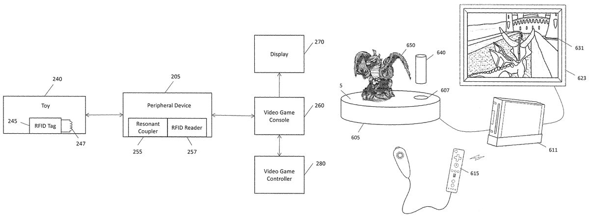
FIG. 2is a block diagram of an example of a video game system in accordance with aspects of the invention. The video game system includes a video game device, shown as a video game console in the embodiment ofFIG. 2. In various embodiments, however, the video game device may be some other computer device, for example a personal computer, laptop, smartphone, tablet, or other computer device. The video game device includes at least one processor for executing program instructions providing for play of a video game associated circuitry, for example, for communicating with input and output devices, user input devices such as a game controller280providing user inputs, a display device270for displaying game play action, and a peripheral device205. The peripheral device includes circuitry for communicating with a toy, for example toy240.
The toy240generally provides a housing, with a radio frequency identification (RFID) tag245within the housing. InFIG. 2an inductive antenna247is shown coupled to the RFID tag, although in various embodiments the inductive antenna may be considered part of the RFID tag. In various embodiments the inductive antenna247of the toy includes an inductor with a ferromagnetic core, which in some embodiments is a ferrite core. In some embodiments the inductive antenna includes a capacitor, to form an LC circuit (the LC circuit is generally tuned, by way of component selection, to have a resonant frequency at a communication frequency of a RFID reader of the peripheral, discussed below). In some embodiments, however, the inductive antenna does not include a capacitor, with instead capacitance for the LC circuit being provided by RFID tag. In some such embodiments the capacitance is provided by parasitic input capacitance of an RFID integrated circuit of the RFID tag, and in some embodiments the capacitance is provided solely by parasitic input capacitance of an RFID integrated circuit of the RFID tag.
The RFID tag stores data, for example, information of a character or a plurality of characters of the video game executed on the game device. In some embodiments, the information of the character is an identification of a character. In some embodiments, information of the character includes information as to the characteristics, for example capabilities, of the character. In some embodiments the toy may be in the shape of a character of the video game, or a weapon (e.g., a sword, shield, gun, cannon, bow and arrow, etc.) to be held by the character in the video game, or an item of clothing or some other accessory (e.g., hat, helmet, jacket, backpack, etc.) to be worn by the character, or some other shape.
The peripheral device205, in some embodiments, includes a substantially flat upper surface for placement of one or more toys (e.g., toy240) thereon. An RFID reader257includes an antenna positioned about the flat upper surface, for example under the flat upper surface, for communication with toys on the surface. In some embodiments, the peripheral device205may include a cavity for receiving at least part of the toy. The cavity in some embodiments is about an edge of the flat upper surface, and signal strength provided by the RFID reader antenna to and from toys at least partially in the cavity may not be sufficient for reliable communications. The peripheral therefore includes a resonant coupler255to strengthen signals passing between the toy and the RFID reader. In some embodiments the resonant coupler is positioned about the location of the cavity, so as to strengthen signals to or from the toy. In some embodiments the resonant coupler comprises an LC circuit. In some such embodiments the LC circuit has a resonant frequency about a communication frequency of the RFID reader, so as to increase strength of signals at that frequency.
The processor of the game console generally commands game play display on the display device270in response from the user input devices (e.g., the game controller280). In some embodiments, the processor commands game play display of game characters in and interacting with a virtual world of game play and possibly each other. In addition, the processor, in response to inputs from the peripheral device105, for example inputs based on information read from the toy240, commands adding characters and objects to the virtual world, with the characters able to manipulate the added objects and move about the virtual world. For example, the processor may include characters in game play based on inputs from the peripheral device205, and the processor may control actions and activities of game characters based on inputs from the user input devices (e.g., game controller280). Furthermore, the processor, in response to inputs from the peripheral device205, may be used to change the characteristics, powers, and/or attributes of characters and objects in the virtual world. For example, a character in game play may have one or more characteristics, powers, and/or attributes associated with it, such as health, strength, power, speed, wealth, shield, weapons, special abilities, spells, or achievement level, for example. The processor may alter one or more characteristics, powers, and/or attributes associated with a character in response to inputs from the peripheral device205.
The program instructions providing for game play is generally stored on removable media such as an optical disk. Accordingly, the game console180may include an optical drive, for example, a DVD-ROM, CD-ROM or Blu-ray drive, for reading the program instructions for game play. In some embodiments, the removable media may be a flash memory data storage device, a hard disk, or a solid-state disk. In some embodiments, the game console260may be a personal computer that includes, for example, a built-in display and built-in user input devices such as a keyboard and a touch pad or mouse. In other embodiments, the program instructions providing for game play may be stored in a remote server that is accessed by a computer or mobile device. In yet other embodiments, the instructions providing for game play may be stored on the local memory of the game console.
In some embodiments the display device is integral to the game device, for example as may be the case if the game device is a smartphone or tablet. In other embodiments the display device may be physically separate from the game device, as illustrated inFIG. 2, which shows a game console and separate display device. The display device270is generally coupled to the game console260by a cable, although in some embodiments a wireless connection may be used. In some embodiments, audio and video contents are transferred from the game console260to the display device270using audio/video interfaces, for example, high-definition multimedia interface (HDMI), component video, and RCA connectors. In many embodiments, the display device270is a liquid crystal display (LCD). In some embodiments, the display device is a television. In some embodiments, the display device is a cathode ray display, a plasma display, an electroluminescent display, an LED or OLED display, or other display. A display screen of the display device270displays video images of game play, generally as commanded by the processor of the game console260or other associated circuitry of the game console.
FIG. 3illustrates aspects of a system in accordance with aspects of the invention. InFIG. 3, a toy311includes an inductor313. In some embodiments the toy is the toy ofFIG. 2. The inductor is generally connected to RFID circuitry (not shown), which is generally in the form of integrated circuitry. The inductor313serves as an antenna for receiving and transmitting signals for the RFID circuitry. The RFID circuitry, or circuitry associated with the RFID circuitry, includes memory to store information relating to a game character of the video game. In some embodiments the information identifies the game character, and in some embodiments the information is the identity of the game character and information relating to various capabilities of the game character.
Information in the memory of or associated with the RFID circuitry may be read (and in some embodiments written) by an RFID reader, of which an inductive coil343is shown inFIG. 3. In the embodiment ofFIG. 3, a resonant coupler321is also used, to increase strength of signals passed between the RFID toy and the RFID reader. The coil of the RFID reader and the resonant coupler may both be in a peripheral device, for example the peripheral device ofFIG. 2in some embodiments.
The resonant coupler321generally serves to couple an electromagnetic field (e.g., electromagnetic field335) between the coil of the RFID reader and the inductor of the toy. In some embodiments, the resonant coupler321is the same as or similar to the resonant antenna extender or resonant coupler255ofFIG. 2. In some embodiments, the resonant coupler321may include an inductor and a capacitance, often in the form of a capacitor, having a resonant frequency about a radio communication frequency of the RFID reader.
FIG. 4is a semi-schematic, semi-block diagram of portions of a peripheral device411and toy421in accordance with aspects of the invention. In some embodiments, the portions of the peripheral may be portions of the peripheral device ofFIG. 2. Similarly, in some embodiments the portions of the toy may be portions of the toy ofFIG. 2.
The peripheral device includes an RFID reader, including a reader RFID antenna403. The RFID antenna includes an inductor407. Generally the RFID reader is configured for communications about a desired frequency, and the inductor307of the RFID antenna may have an inductance selected such that an LC circuit formed using the inductor has a resonant frequency about the desired frequency.
The peripheral device also includes a resonant coupler423. The resonant coupler includes an inductor427and a capacitor429, forming another LC circuit. Inductance of the inductor427and capacitance of the capacitor429are in most embodiments selected such that the LC circuit of the resonant coupler has a resonant frequency about the communication frequency of the RFID reader.
The toy421includes an RFID tag443, having an RFID integrated circuit445and an antenna formed of an inductor447and a capacitor449, although in some embodiments the antenna may be external to the RFID tag. The inductor447and the capacitor449form an LC circuit, with their inductance and capacitance, respectively, selected such that a resonant frequency of the LC circuit is about the communication frequency of the RFID reader of the peripheral. In some embodiments the capacitor449is not used, with instead input capacitance of the RFID integrated circuit providing capacitance of the LC circuit.
In operation, The RFID reader communicates with the RFID tag443of the toy. Signals between the reader RFID antenna and the RFID tag may be strengthened by the resonant coupler, improving communications between a reader of the peripheral device and the toy.
Although not depicted inFIG. 4, the peripheral device may include an upper surface for placement of toys thereon, and a cavity for receiving at least portions of those and/or other toys. The reader RFID antenna may be integrated inside the peripheral device, and in some embodiments may be positioned at or about a center of the peripheral device. The cavity for receiving portions of toys, however, may be close to an edge of the peripheral device, sufficiently distant from the reader RFID antenna to potentially result in difficulties when the reader attempts to communicate with the toy. In some embodiments, therefore, the resonant coupler may be integrated into the peripheral device about the location of the cavity, so as to improve communications between the toy and the reader. In some embodiments the resonant coupler may be underneath the cavity, next to the cavity, or have a coil of the inductor of the resonant coupler encompassing the cavity.
FIG. 5is a semi-schematic, semi-block diagram of a further RFID tag in accordance with aspects of the invention. The RFID tag, which in the case ofFIG. 5is shown as including an inductive antenna, may in some embodiments be used as the RFID tag of the toy ofFIG. 2or other figures.
InFIG. 5, an inductor547is coupled to a radio-frequency identification (RFID) integrated circuit545. The RFID integrated circuit545, in some embodiments, is the same as or similar to the RFID integrated circuit ofFIG. 4. The RFID integrated circuit545, for example, may demodulate electrical signals received from inductor547and store data reflecting or writable to reflect information of a character or a plurality of characters of a video game, and which may be represented by the toy in some embodiments. In some embodiments, the RFID integrated circuit545may modulate electrical signals to transmit information of the character or plurality of characters using inductor547to an RFID reader.
The RFID integrated circuit ofFIG. 5is shown as having a capacitance549across inputs for the inductor. In some embodiments the capacitance is a capacitor of the RFID integrated circuit. In various embodiments, however, the RFID integrated circuit does not include such a capacitor. Instead, the capacitance is an input parasitic capacitance of the RFID integrated circuit.
The capacitance, in most embodiments, is used in conjunction with inductance of the inductor547to tune or control resonant frequency of an LC circuit formed of the inductor and capacitance. For example, in some embodiments the input parasitic capacitance of the RFID integrated circuit is 20 pico-Farads, and an RFID reader is expected to communicate at a frequency of 13.56 MegaHertz. In such circumstances an inductor with an inductance of 6.8 micro-Henrys is utilized to provide an LC circuit with a resonant frequency also of 13.56 Mega-Hertz.
FIG. 6illustrates a further example of a video game system in accordance with aspects of the invention. The video game system comprises a game console611that includes at least one processor for executing program instructions providing for video game play of a video game and associated circuitry, for example, for communicating with input and output devices, user input devices such as a game controller615, a display device623for displaying game play action, a peripheral device605, a toy640, and a toy650.
The game console, game controller, and display device are, in various embodiments, the same as or similar to the game device, game controller, and display device, respectively, ofFIG. 2. Similarly, the peripheral605may be the same as or similar to the peripheral ofFIG. 2, with the peripheral605including for example an RFID reader and a resonant coupler. The toys640and650also include a writeable RFID tag, including an associated antenna, the same as or similar to the toys and/or RFID tags and circuitry discussed with respect to the other figures.
The processor of the game console611generally commands game play display on the display device623in response from the user input devices (e.g., the game controller615). In some embodiments, the processor commands game play display of game characters in and interacting with a virtual world of game play and possibly each other. In addition, the processor, in response to inputs from the peripheral device605, for example inputs based on information read from the toy640or the toy650, commands adding characters and objects to the virtual world, with the characters able to manipulate the added objects and move about the virtual world. For example, the processor may include characters in game play based on inputs from the peripheral device605, and the processor may control actions and activities of game characters based on inputs from the user input devices (e.g., game controller615). Furthermore, the processor, in response to inputs from the peripheral device605, may be used to change the characteristics, powers, and/or attributes of characters and objects in the virtual world. For example, a character in game play may have one or more characteristics, powers, and/or attributes associated with it, such as health, strength, power, speed, wealth, shield, weapons, special abilities, spells, or achievement level, for example. The processor may alter one or more characteristics, powers, and/or attributes associated with a character in response to inputs from the peripheral device605.
The program instructions providing for game play is generally stored on removable media such as an optical disk. Accordingly, the game console611may include an optical drive, for example, a DVD-ROM, CD-ROM or Blu-ray drive, for reading the program instructions for game play. In some embodiments, the removable media may be a flash memory data storage device, a hard disk, or a solid-state disk. In some embodiments, the game console611may be a personal computer that includes, for example, a built-in display and built-in user input devices such as a keyboard and a touch pad or mouse. In other embodiments, the program instructions providing for game play may be stored in a remote server that is accessed by a computer or mobile device. In yet other embodiments, the instructions providing for game play may be stored on the local memory of the game console.
The display device623is generally coupled to the gaming console611by a cable, although in some embodiments a wireless connection may be used. In some embodiments, audio and video contents are transferred from the gaming console611to the display device623using audio/video interfaces, for example, high-definition multimedia interface (HDMI), component video, and RCA connectors. In many embodiments, the display device623is a liquid crystal display (LCD). In some embodiments, the display device is a television. In some embodiments, the display device is a cathode ray display, a plasma display, an electroluminescent display, an LED or OLED display, or other display. A display screen631of the display device623displays video images of game play, generally as commanded by the processor of the game console611or other associated circuitry of the gaming platform. As illustrated inFIG. 6, the display screen631shows a screen shot of video game play. The screen shot shows a display of a character, generally controlled by and animated in accordance with user inputs, approaching an inanimate item in the form of what may be considered a castle.
The toy650is shown as a fantastical creature, as illustrated generally similar to a dragon, with the fantastical creature atop a substantially flat upper surface625of the peripheral. The toy650includes a rewritable RFID tag that stores data, for example, reflecting or writable to reflect information of a character in the video game, with for example the character resembling the fantastical creature. In some embodiments, the information of the character is an identification of a character. In some embodiments, information of the character includes information as to the characteristics, for example capabilities, of the character.
The toy640is shown in the shape of a cylinder, although in various embodiments the toy640may have other shapes. Like the toy650, the toy640includes a rewritable RFID tag that stores data, for example, reflecting or writable to reflect information of a character in the video game. The toy640is not atop the substantially flat surface of the peripheral, however. Instead, the toy640is proximate a cavity607in the upper surface of the peripheral, with the toy640and cavity both dimensioned such that the toy may be partially inserted into the cavity.
The RFID tag and antenna are within the toy640(and similarly the toy650). The toy640may therefore be considered to be comprised of a housing, providing the external shape of the toy, and an RFID tag and antenna within the housing. In various embodiments the RFID and antenna comprise, and in some embodiments consist of, an RFID integrated circuit and an inductor. In some embodiments the inductor has coils centered about a longitudinal axis of the inductor. In some embodiments the longitudinal axis of the inductor is parallel to a longitudinal axis of the housing of the toy, with in some embodiment there being no offset between the two.
The resonant coupler is positioned proximate to the cavity of the peripheral, in some embodiments below the cavity. Such positioning of the cavity is believed to increase strength of signals passing between the toy640, while in the cavity, and the RFID reader of the peripheral. Further, in various embodiments the cavity is configured so as to keep the toy640in a predefined orientation, at least with respect to one axis of the toy, and in some embodiments the one axis of the toy is an axis defined by a longitudinal axis of the inductor. In some such embodiments the cavity is so configured so as to align magnetic fields generated by the inductor of the antenna of the toy with an inductor of the resonant coupler.
Although the invention has been discussed with respect to various embodiments, it should be recognized that the invention comprises the novel and non-obvious claims supported by this disclosure.
Claims
- A video game system, comprising: a toy including an inductor connected to a radio frequency identifier (RFID) integrated circuit, the RFID integrated circuit including memory to store information related to a video game character, the inductor and an input capacitance provided by the RFID integrated circuit forming a resonant circuit with a resonant frequency inversely proportional to a square root of inductance of the inductor and capacitance of the input capacitance provided by the RFID integrated circuit;a peripheral device including RFID reader circuitry and a resonant coupler, the RFID reader circuitry configured to transmit signals at a frequency about the resonant frequency of the resonant circuit of the toy, the resonant coupler having a resonant frequency about the resonant frequency of the resonant circuit of the toy;and a video game device coupled to the peripheral device, the video game device configured to command the peripheral to write the information related to the video game character to the toy, to read the information related to the video game character from the toy, and to provide for video game play in which a user controls the video game character, wherein the peripheral device includes a cavity for receiving at least a portion of the toy, and wherein the resonant coupler is positioned about the cavity of the peripheral.
- A video game system, comprising: a toy including an inductor connected to a radio frequency identifier (RFID) integrated circuit, the RFID integrated circuit including memory to store information related to a video game character, the inductor and an input capacitance provided by the RFID integrated circuit forming a resonant circuit with a resonant frequency inversely proportional to a square root of inductance of the inductor and capacitance of the input capacitance provided by the RFID integrated circuit;a peripheral device including RFID reader circuitry and a resonant coupler, the RFID reader circuitry configured to transmit signals at a frequency about the resonant frequency of the resonant circuit of the toy, the resonant coupler having a resonant frequency about the resonant frequency of the resonant circuit of the toy;and a video game device coupled to the peripheral device, the video game device configured to command the peripheral to write the information related to the video game character to the toy, to read the information related to the video game character from the toy, and to provide for video game play in which a user controls the video game character, wherein the resonant frequency of the resonant frequency of the toy is 13.56 MegaHertz.
- A video game system, comprising: a toy including an inductor connected to a radio frequency identifier (RFID) integrated circuit, the RFID integrated circuit including memory to store information related to a video game character, the inductor and an input capacitance provided by the RFID integrated circuit forming a resonant circuit with a resonant frequency inversely proportional to a square root of inductance of the inductor and capacitance of the input capacitance provided by the RFID integrated circuit;a peripheral device including RFID reader circuitry and a resonant coupler, the RFID reader circuitry configured to transmit signals at a frequency about the resonant frequency of the resonant circuit of the toy, the resonant coupler having a resonant frequency about the resonant frequency of the resonant circuit of the toy;and a video game device coupled to the peripheral device, the video game device configured to command the peripheral to write the information related to the video game character to the toy, to read the information related to the video game character from the toy, and to provide for video game play in which a user controls the video game character, wherein the inductor has an inductance of 6.8 micro-Henrys.
- A toy for use in a video game system, comprising: a housing;a radio frequency identifier (RFID) circuit within the housing, the RFID circuit configured for operation about a desired radio frequency, the RFID circuit including memory for storing information related to a video game character;and an inductive antenna coupled to the RFID circuit, the inductive antenna consisting of an inductor with a ferromagnetic core, the inductor having an inductance such that a circuit formed by the inductor and an input capacitance of the RFID circuit resonates about the desired radio frequency.
- The toy of claim 4 , wherein the ferromagnetic core comprise a ferrite core.
- The toy of claim 4 , wherein the inductive antenna is within the housing.
- The toy of claim 4 , wherein the toy is in the form of a video game character.
- The toy of claim 4 , wherein the housing is dimensioned to at least partially fit in a cavity of a peripheral device including an RFID reader.
Disclaimer: Data collected from the USPTO and may be malformed, incomplete, and/or otherwise inaccurate.