U.S. Pat. No. 9,597,592
METHOD AND APPARATUS FOR PROCESSING VIRTUAL WORLD
AssigneeSamsung Electronics Co Ltd
Issue DateDecember 26, 2012
Illustrative Figure
Abstract
A virtual world processing apparatus and method. An angle value is obtained by measuring an angle of a body part of a user of a real world using sensor capability, which is information on capability of a bending sensor, and is transmitted to a virtual world, thereby achieving interaction between the real world and the virtual world. In addition, based on the sensor capability and the angle value denoting the angle of the body part, control information is generated to control a part of an avatar of the virtual world, corresponding to the body part, and then transmitted to the virtual world. Accordingly, interaction between the real world and the virtual world is achieved.
Description
DETAILED DESCRIPTION Reference will now be made in detail to example embodiments, examples of which are illustrated in the accompanying drawings, wherein like reference numerals refer to the like elements throughout. Example embodiments are described below to explain the present disclosure by referring to the figures. FIG. 1illustrates a virtual world processing system that controls data exchange between a real world and a virtual world, according to example embodiments. Referring toFIG. 1, the virtual world processing system includes a real world110, a virtual world processing apparatus, and a virtual world140. The real world110may denote a sensor that detects information on the real world110or a sensory device that implements information on the virtual world140in the real world110. The virtual world140may denote the virtual world140itself implemented by a program or a sensory media playing apparatus that plays contents including sensory effect information implementable in the real world110. A sensor according to example embodiments may sense information on a movement, state, intention, shape, and the like of a user in the real world110, and transmit the information to the virtual world processing apparatus. Depending on embodiments, the sensor may transmit sensor capability101, sensor adaptation preference102, and sensed information103to the virtual world processing apparatus. The sensor capability101may denote information on the capability of the sensor. The sensor adaptation preference102may denote information on preference of the user with respect to the sensor capability. The sensed information103may denote information sensed in relation to the real world110by the sensor. The virtual world processing apparatus may include an adaptation real world to virtual world (RV)120, virtual world information (VWI)104, and an adaptation real world to virtual world/virtual world to real world (RV/VR)130. The adaptation RV120may convert the sensed information103sensed by the sensor in relation to the real world110to information applicable to the virtual world140, based on the sensor ...
DETAILED DESCRIPTION
Reference will now be made in detail to example embodiments, examples of which are illustrated in the accompanying drawings, wherein like reference numerals refer to the like elements throughout. Example embodiments are described below to explain the present disclosure by referring to the figures.
FIG. 1illustrates a virtual world processing system that controls data exchange between a real world and a virtual world, according to example embodiments.
Referring toFIG. 1, the virtual world processing system includes a real world110, a virtual world processing apparatus, and a virtual world140.
The real world110may denote a sensor that detects information on the real world110or a sensory device that implements information on the virtual world140in the real world110.
The virtual world140may denote the virtual world140itself implemented by a program or a sensory media playing apparatus that plays contents including sensory effect information implementable in the real world110.
A sensor according to example embodiments may sense information on a movement, state, intention, shape, and the like of a user in the real world110, and transmit the information to the virtual world processing apparatus.
Depending on embodiments, the sensor may transmit sensor capability101, sensor adaptation preference102, and sensed information103to the virtual world processing apparatus.
The sensor capability101may denote information on the capability of the sensor. The sensor adaptation preference102may denote information on preference of the user with respect to the sensor capability. The sensed information103may denote information sensed in relation to the real world110by the sensor.
The virtual world processing apparatus may include an adaptation real world to virtual world (RV)120, virtual world information (VWI)104, and an adaptation real world to virtual world/virtual world to real world (RV/VR)130.
The adaptation RV120may convert the sensed information103sensed by the sensor in relation to the real world110to information applicable to the virtual world140, based on the sensor capability101and the sensor adaptation preference102. Depending on embodiments, the adaptation RV120may be implemented by an RV engine.
The adaptation RV120according to example embodiments may convert the VWI104using the converted sensed information103.
The VWI104denotes information on a virtual object of the virtual world140.
The adaptation RV/VR130may generate virtual world effect metadata (VWEM)107, which denotes metadata related to effects applied to the virtual world140, by encoding the converted VWI104. Depending on embodiments, the adaptation RV/VR130may generate the VWEM107based on virtual world capabilities (VWC)105and virtual world preferences (VWP)106.
The VWC105denotes information on characteristics of the virtual world140. The VWP106denotes information on preferences of the user with respect to the characteristics of the virtual world140.
The adaptation RV/VR130may transmit the VWEM107to the virtual world140. Here, the VWEM107may be applied to the virtual world140so that effects corresponding to the sensed information103may be implemented in the virtual world140.
According to an aspect of the present disclosure, an effect event generated in the virtual world140may be driven by a sensory device, that is, an actuator in the real world110.
The virtual world140may encode sensory effect information, which denotes information on the effect event generated in the virtual world140, thereby generating sensory effect metadata (SEM)111. Depending on embodiments, the virtual world140may include the sensory media playing apparatus that plays contents including the sensory effect information.
The adaptation RV/VR130may generate sensory information112based on the SEM111. The sensory information112denotes information on an effect event implemented by the sensory device of the real world110.
The adaptation VR150may generate information on a sensory device command (SDcmd)115for controlling operation of the sensory device of the real world110. Depending on embodiments, the adaptation VR150may generate the information on the SDcmd115based on information on sensory device capabilities (SDCap)113and information on user sensory preference (USP)114.
The SDCap113denotes information on capability of the sensory device. The USP114denotes information on preference of the user with respect to an effect implemented by the sensory device.
FIG. 2illustrates a structure of a virtual world processing apparatus200according to example embodiments.
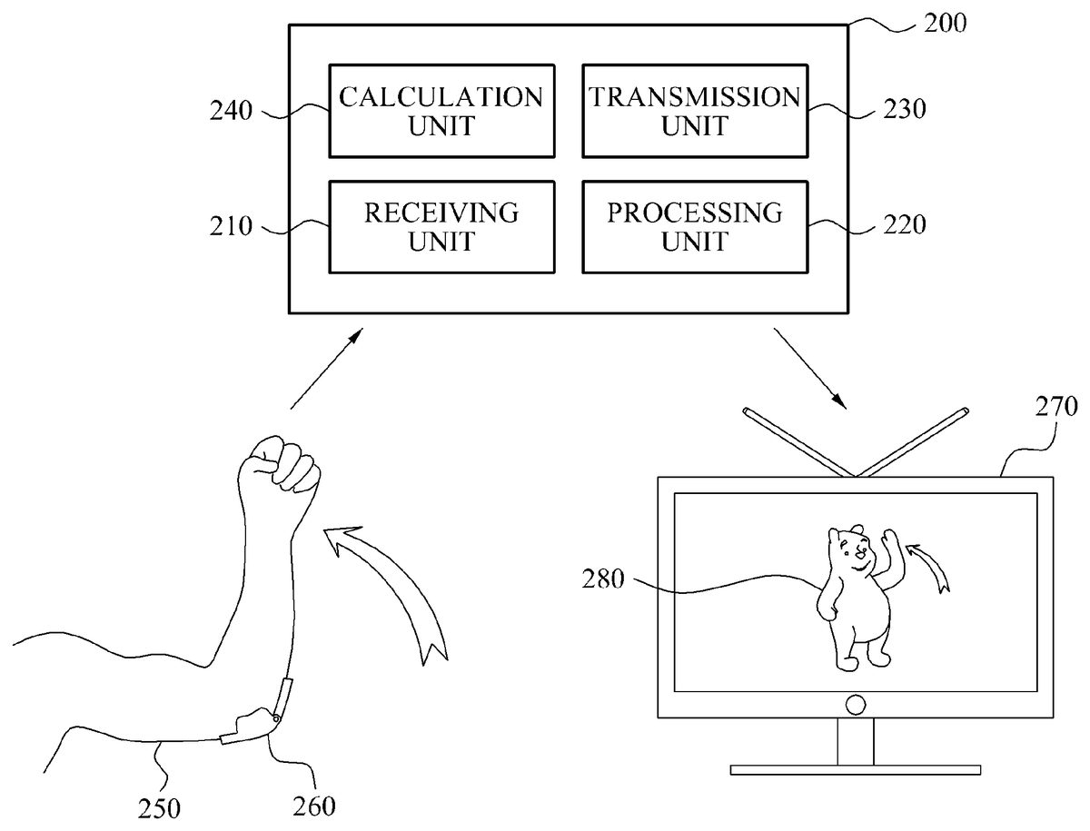
Referring toFIG. 2, the virtual world processing apparatus200includes a receiving unit210, a processing unit220, and a transmission unit230. In another example embodiment, which will be discussed later, the virtual world processing apparatus200additionally includes a calculation unit240.
The receiving unit210may receive, from a bending sensor260, an angle value of a sensed location measured by the bending sensor260and sensor capability related to capability of the bending sensor260.
The bending sensor260measures sensed information related to a bending degree of an object of a real world. The sensed information denotes a measured value of the bending degree, that is, an angle of the sensed location measured by the bending sensor260.
Depending on embodiments, the bending sensor260may be attached or connected to the sensed location to measure the bending degree, that is, the angle of the sensed location. For example, when a user250attaches the bending sensor260to an elbow, the bending sensor260may sense a bending degree of the elbow of the user, that is, an angle of the elbow. Here, the bending sensor260may transmit an angle value of the elbow and sensor capability of the bending sensor260to the virtual world processing apparatus200, thereby controlling an elbow movement of an avatar, for example. As shown inFIG. 2, as an example, when the user250rotates an elbow, such that an arm rotates upward, the virtual world processing apparatus200may process the angle value and sensor capability, transmitted by the bending sensor260, thereby controlling an avatar280.
The bending sensor260may be connected to other joints of the user250, including elbows, finger joints, a neck, shoulders, and the like, to measure bending degrees of the joints.
The sensor capability denotes the capability of the bending sensor260.
According to example embodiments, the sensor capability of the bending sensor260may include maxValue, minValue, Num of Locations, Distance between Location, numOfAxes, and numOfSensors, however, the present disclosure is not limited thereto.
The maxValue may denote a maximum angle value measurable by the bending sensor260. The minValue may denote a minimum angle value measurable by the bending sensor260. The bending sensor260may measure an angle of the sensed location within a range from greater than the minValue to smaller than the maxValue.
The Num of Locations may denote the number of the sensed locations sensed by the bending sensor260. According to an aspect of the present disclosure, the bending sensor260may singly and simultaneously sense bending degrees of a plurality of sensed locations. Here, the Num of Locations may be a number of the plurality of sensed locations measured by the single bending sensor260. Depending on embodiments, a plurality of the bending sensors260may measure a plurality of the sensed locations. In this case, the Num of Locations may be a number of the plurality of sensed locations measured by the plurality of the bending sensors260.
The Distance between Location may denote the distance between the adjacent sensed locations. A plurality of the bending sensors260may sense a plurality of the sensed locations.
The numOfAxes may denote dimension of the angle value measurable by the bending sensor260.
The numOfSensors may denote segments measurable by a plurality of the bending sensors260when the plurality of sensed locations are measured by the plurality of the bending sensors260.
Depending on embodiments, the sensor capability of the bending sensor260may further include accuracy and offset.
The accuracy may denote information on a measurement error.
The offset may denote a value for zero point adjustment of the angle value measured by the bending sensor260.
Table 1 shows an extensible markup language (XML) syntax with respect to a bending sensor capability type according to example embodiments. The bending sensor capability type may denote information on basic sensor capability of the bending sensor260.
TABLE 1
Table 2 shows semantics related to the bending sensor capability type according to example embodiments.
TABLE 2NameDefinitionBendingSensorCapabilityTypeTool for describing a bendingsensor capability.maxValueDescribes the maximum value that thebending sensor can perceivein terms of degree.minValueDescribes the minimum valuethat the bending sensor canperceive in terms of degree.numOfLocationsDescribes the number of locations thata bending sensor cansense bending angles.distanceBtwnLocationsDescribes the distance between theadjacent sensing locations.numOfAxesDescribes the dimension that the bendingsensor can perceive the bending angles.numOfSensorsDescribes the number of segments thatan array of bending sensors can perceive.
According to an aspect of the present disclosure, the sensor capability may include metadata encoded into a binary format. In details, the bending sensor260may generate the metadata by encoding the sensor capability into the binary format, and transmit the metadata to the virtual world processing apparatus200. Here, the receiving unit210may receive the sensor capability that includes the metadata encoded into the binary format.
Table 2-2 shows binary representation syntax related to the bending sensor capability type, according to example embodiments.
TABLE 2-2(NumberBendingSensorCapabilityType{of bits)(Mnemonic)numOfLocationFlag1bslbfdistanceBtwnLocationFlag1bslbfnumOfAxisFlag,1bslbfnumOfSensorsFlag1bslbfSensorCapabilityBaseSensorCapabilityBaseTypeif(numOfLocationFlag){numOfLocation16uimsbf}if(distanceBtwnLocationFlag){distanceBtwnLocation32fsbf}if(numOfAxesFlag){numOfAxes2uimsbf}if(numOfSensorsFlag){numOfSensors8uimsbf}}
Table 2-3 shows semantics related to binary encoding of the bending sensor capability type, according to example embodiments.
TABLE 2-3NameDefinitionnumOfLocationFlagThis field, which is only present in the binary representation,indicates the presence of the “numOfLocation” attribute. A valueof “1” implies that the attribute shall be used and a value of “0”implies that the attribute shall not be used.distanceBtwnLocationFlagThis field, which is only present in the binary representation,indicates the presence of the “distanceBtwnLocation” attribute. Avalue of “1” implies that the attribute shall be used and a value of“0” implies that the attribute shall not be used.numOfAxesFlagThis field, which is only present in the binary representation,indicates the presence of the “numOfAxes” attribute. A value of“1” implies that the attribute shall be used and a value of “0”implies that the attribute shall not be used.numOfSensorsFlagThis field, which is only present in the binary representation,indicates the presence of the “numOfSensors” attribute. A value of“1” implies that the attribute shall be used and a value of “0”implies that the attribute shall not be used.NumOfLocationsSame as above.For the binary representation, the type of data is 16-bit unsignedinteger.DistanceBtwnLocationsSame as above.For the binary representation, the type of data is 32 bit floatingvalue.numOfAxesSame as above.For the binary representation, 2-bit data field is reserved tosupport up to 3 axes.numOfSensorsSame as above.For the binary representation, 8-bit data field is reserved tosupport an array of bend sensors.
Referring to Table 2-3, the metadata encoded into the binary format may include a data field related to at least one attribute selected from the Num of Locations, the numOfAxes, and the numOfSensors, for example. That is, the sensor capability which is the metadata encoded into the binary format may limit data size by including the data field related to the at least one attribute selected from the Num of Locations, the numOfAxes, and the numOfSensors, for example.
Table 3 shows an example sensor capability of the bending sensor260.
TABLE 3cidl:SensorDeviceCapability xsi:type=“scdv:BendingSensorCapabilityType” id=“BS001” maxValue=“90.0”minValue=“−30.0” numOfLevels=“2500” offset=“0.05” >
Referring to Table 3, an identifier ID of the bending sensor260may be ‘BS001.’ The maxValue of the bending degree, that is, the angle, of the sensed location measurable by the bending sensor260may be ‘90.0 degree’ while the minValue may be ‘−30.0 degree.’ In addition, a number of levels (numOfLevels) may be ‘2500 level.’ The accuracy of the bending sensor260may be ‘0.1 degree.’ The offset of the bending sensor260may be ‘0.05 degree.’
Table 4 shows XML syntax with respect to a bending sensor type according to an example embodiment. The bending sensor type may denote information on the sensed information measured by the bending sensor260.
TABLE 4
The bending sensor type according to example embodiments may include Timestamp, Unit, and Value.
The Timestamp denotes information on time when the bending sensor260measures the angle value of the sensed location. Depending on embodiments, the Timestamp may be information on an interval of time when the bending sensor260measures the angle value.
The Unit denotes a unit of the angle measured by the bending sensor260. Depending on embodiments, the Unit may include ‘degree.’
The Value denotes an angle value measured by the bending sensor260. Depending on embodiments, when a plurality of the bending sensors260measure the angle value with respect to one sensed location, the angle value of the sensed location may be a sum total of a plurality of angle values measured by the plurality of bending sensors260.
Hereinafter, an operation of measuring the angle value by the plurality of the bending sensors260will be described with reference toFIG. 3.
FIG. 3illustrates an operation of measuring a sensed location by a plurality of bending sensors310, according to example embodiments.
Referring toFIG. 3, the plurality of the bending sensors310may measure a bending degree, that is, an angle, of a sensed location320.
Here, a sum total of angle values measured by the plurality of the bending sensors310may represent the total angle value of the sensed location320. For example, when ten bending sensors310measure the angle values of the sensed location320, and the respective angle values measured by the bending sensors310are 1 degree, 3 degrees, 5 degrees, 10 degrees, 12 degrees, 12 degrees, 9 degrees, 5 degrees, 2 degrees, and 1 degree, the angle value of the sensed location320may be 60 which is the sum total of the respective angle values.
Referring back toFIG. 2, Table 4-2 shows semantics related to the bending sensor type according to the above example embodiment.
TABLE 4-2NameDefinitionBendingSensorTypeTool for describing sensed information withrespect to a Bending sensor.TimeStampDescribes the time that the information isacquired (sensed).unitSpecifies the unit of the sensed value, if a unitother than the default unit is used, as areference to a classification scheme termprovided by UnitTypeCS defined in A.2.1 ofISO/IEC 23005-6. If the unit is not definedhere, the default unit is degree.valueDescribes the sensed value by the bendingwith respect to the default unit orthe unit defined in the unit attribute. The valuescan be multiple if the bending sensor providesmultiple angle values at multiple locations.
Table 4-3 shows binary representation syntax related to the bending sensor type according to the above example embodiment.
TABLE 4-3NumberBendSensorType{of bitsMnemonicunitFlag1bslbfSensedInfoBaseTypeSensedInfoBaseTypenumOfSensors16uimsbfnumOfAxis2uimsbfnumOfLocations16uimsbffor(i=0 ;k<numOfSamples ;i ++){for(j = 0; j< numOfAxis; j++){for(k=0;k< numOfLocations;k++){ArrayValue[ (i-1)* numOfLocation*32fsbfnumOfAxis + (j-1)* NumOfLocations + k ]}}If (unitFlag == 1){unitunitType}}
Table 4-4 shows semantics related to binary encoding of the bending sensor type according to the above example embodiment.
TABLE 4-4NameDefinitionnumOfSensorsThis field, which is only present in the binaryrepresentation, signals the number of bend sensors.numOfAxisThis field, which is only present in thebinary representation, signals the dimensionof the data at the sensing locations.numOfLocationsThis field, which is only present in the binaryrepresentation, signals the number of sensing locations.
Table 5 shows XML syntax with respect to a bending sensor type according to another example embodiment.
TABLE 5
Table 5-2 shows semantics related to the bending sensor type according to this example embodiment.
TABLE 5-2NameDefinitionBendingSensorTypeTool for describing sensed information withrespect to a Bending sensor.TimeStampDescribes the time that the informationis acquired (sensed).unitSpecifies the unit of the sensed value, if a unitother than the default unit is used, as areference to a classification schemeterm provided by UnitTypeCS defined inA.2.1 of ISO/IEC 23005-6. If the unit is notdefined here, the default unit is degree.ArrayBendingValueDescribes the sensed value by bending accordingto 3-axis with respect to the default unitor the unit defined in the unit attribute.Note: the ArrayValue defines by the number oflocations and the number of axis.Ten by three matrix indicates that thearrayValue has 10 sensing locations, each ofwhich has 3-axis bending angles.valueDescribes the sensed value by bending in scalar.This element shall be used, if the sensor iscapable of sensing only a degree of bending.
Table 6 shows XML syntax with respect to a bending sensor type according to yet another example embodiment.
TABLE 6
Table 6-2 shows semantics related to the bending sensor type according to this example embodiment.
TABLE 6-2NameDefinitionBendingSensorTypeTool for describing sensed information withrespect to a Bending sensor.TimeStampDescribes the time that the informationis acquired (sensed).unitSpecifies the unit of the sensed value, if a unitother than the default unit is used,as a reference to a classification schemeterm provided by UnitTypeCS defined in A.2.1of ISO/IEC 23005-6. If the unit is not definedhere, the default unit is degree.ArrayBendingValueDescribes the set of sensed values by the bendingwith respect to the default unit or the unit definedin the unit attribute on each joint.Note: the ArrayValue defines by the number ofaxes and the number of locations. Threeby ten matrix indicates that thearrayValue has 10 sensing locations, each of whichhas 3-axis bending angles. The orderof values in each row of the matrixmay be started from the fingertip to the palm side.
Table 7 shows binary representation syntax related to a bending sensor type according to example embodiments.
TABLE 7Num-berBendSensorType{of bitsMnemonicunitFlag1bslbfSensedInfoBaseTypeSensedInfoBaseTypenumOfSensors16uimsbfnumOfAxes2uimsbfnumOfLocations16uimsbffor(i=0 ;k<numOfSensors ;i ++ ){for(j = 0; j< numOfAxes; j++){for(k=0;k< numOfLocation;k+ + ){ArrayValue [ (i-1)* numOfLocation*32fsbfnumOfAxis + (j-1)* NumOfLocations + k ]}}If (unitFlag == 1){unitunitType}}
Table 7-2 shows semantics related to binary encoding of the bending sensor type according to example embodiments.
TABLE 7-2NameDefinitionnumOfSensorsThis field, which is only present in thebinary representation,signals the number of bend sensors.numOfAxesThis field, which is only present in thebinary representation, signals the dimensionof the data at the sensing locations.numOfLocationsThis field, which is only present in thebinary representation, signalsthe number of sensing locations.
Table 8 shows an example of sensed information measured by the bending sensor260.
TABLE 8
Referring to Table 8, an ID of the sensed information may be ‘bending01’ and an ID of the bending sensor260may be ‘bendingID01.’ That is, the sensed information measured by the bending sensor260of ‘bendingID01’ may be ‘bending01.’ In addition, a timestamp of the bending sensor260may be ‘60000’ for 100 clock ticks per second.
The processing unit220may generate control information for controlling an object280of a virtual world270corresponding to the sensed location, based on the angle value and the sensor capability.
For example, when an angle of the elbow of the user250changes from 180 degrees to 90 degrees, the bending sensor260may measure the angle value and transmit the angle value to the virtual world processing apparatus200. Here, based on the angle value and the sensor capability, the processing unit220may generate the control information for controlling the object280of the virtual world270, for example an avatar, which corresponds to the sensed location, that is, the elbow, to also move the elbow.
According to an aspect, the processing unit220may generate the control information when the angle value measured by the bending sensor260is within a range, i.e., less than or equal to the maximum value measurable by the bending sensor260and greater than or equal to the minimum value measurable by the bending sensor260.
Depending on embodiments, when the angle value is greater than the maximum value, the processing unit220may generate the control information considering the angle value as the maximum value. When the angle value is less than the minimum value, the processing unit220may generate the control information considering the angle value as the minimum value.
The transmission unit230may transmit the generated control information to the virtual world270.
Depending on embodiments, the transmission unit230may encode the control information into metadata of an XML format and transmit the metadata to the virtual world270. In addition, the transmission unit230may encode the control information into binary metadata and transmit the binary metadata to the virtual world270. Also, the transmission unit230may encode the control information into first metadata of the XML format, encode the first metadata into second metadata of a binary format, and transmit the second metadata to the virtual world270.
The virtual world processing apparatus200may further include a calculation unit240.
The calculation unit240may calculate a third angle value related to a third sensed location disposed between a first sensed location and a second sensed location, based on a first angle value related to the first sensed location and a second angle value related to the second sensed location.
Here, the processing unit220may generate the control information based on the first angle value, the second angle value, the third angle value, and the sensor capability.
Hereinafter, an operation of calculating the third angle value will be described in detail with reference toFIG. 4.
FIG. 4illustrates an operation of calculating an angle value by a virtual world processing apparatus according to example embodiments.
Referring toFIG. 4, a bending sensor410according to the example embodiments may measure a first angle value related to a first sensed location401, for example, a shoulder. Another bending sensor420may measure a second angle value related to a second sensed location403, for example, a wrist.
The virtual world processing apparatus may calculate the third angle value of a third sensed location402not sensed by the bending sensors410and420, based on the first angle value and the second angle value. That is, the number of sensors needed may be reduced as the third angle is calculated using the sensed first angle value and the second angle value.
Depending on embodiments, the virtual world processing apparatus200may set an average of the first angle value and the second angle value as the third angle value.
Depending on embodiments, the virtual world processing apparatus may further include a database collecting and storing the third angle value based on the first angle value and the second angle value. The virtual world processing apparatus may calculate the third angle value based on information stored in the database, the first angle value, and the second angle value.
FIG. 5illustrates a structure of an avatar control features type510according to example embodiments.
Referring toFIG. 5, the avatar control features type510may include attributes520, control body features530, and control face features540, for example.
The avatar control features information denotes information on features of an avatar, used for control of the avatar of a virtual world. Here, the avatar control features type510denotes information on a type of the avatar control features type510.
The attributes520denotes information on attributes of the avatar control features information. Depending on embodiments, the attributes520may include name information of the features, used for control of the avatar.
The control body features530denote features included in a body part of the avatar, used for control of the avatar.
Depending on embodiments, the control body features530may include HeadBones531, UpperBodyBones532, DownBodyBones533, and MiddleBodyBones534.
For example, the UpperBodyBones532may include information on features corresponding to a hand structure of the avatar.
The hand structure may include a sub structure such as a wrist, finger joints, and the like.
Table 9 shows the sub structure of the hand structure according to example embodiments.
TABLE 9LWristLeft wristLHandLeft handLThumbThumb proximal phalangeLPhalanges1Thumb proximal phalangeLThumb2Thumb distal phalangeLPhalanges2Thumb distal phalangeLIndexIndex finger metacarpalLPhalanges3Index finger proximal phalangeLPhalanges4Index finger middle phalangeLPhalanges5Index finger distal phalangeLMiddleMiddle finger metacarpalLPhalanges6Middle finger proximalphalangeLPhalanges7Middle finger middle phalangeLPhalanges8Middle finger distal phalangeLRingRing finger metacarpalLPhalanges9Ring finger proximal phalangeLPhalanges10Ring finger middle phalangeLPhalanges11Ring finger distal phalangeLPinkyPinky metacarpalLPhalanges12Pinky proximal phalangeLPhalanges13Pinky middle phalangeLPhalanges14Pinky distal phalange
According to an aspect, the virtual world processing apparatus may generate control information for controlling the avatar control features corresponding to sensed locations, based on sensed information measured by a bending sensor. That is, the sensed locations measured by the bending sensor may correspond to at least one of the avatar control features.
For example, when the bending sensor measures a bending degree of a wrist of a user, the virtual world processing apparatus may generate the control information for controlling a movement of a wrist of the avatar of the virtual world, which corresponds to the wrist of the user.
FIG. 6illustrates a virtual world processing method according to example embodiments.
Referring toFIG. 6, the virtual world processing method may receive an angle value of a sensed location and sensor capability of a bending sensor, from the bending sensor, in operation610.
The bending sensor may measure sensed information on a bending degree of an object in a real world. The sensed information denotes a measured value of the bending degree, that is, an angle of the sensed location measured by the bending sensor.
Depending on embodiments, the bending sensor may be attached or connected to the sensed location to measure the bending degree, that is, the angle of the sensed location. For example, when a user attaches the bending sensor to an elbow, the bending sensor may sense a bending degree of the elbow, that is, an angle of the elbow. At this time, the virtual world processing method may receive the angle value of the elbow and the sensor capability of the bending sensor, from the bending sensor.
The bending sensor may be connected to other joints of the user, including elbows, finger joints, a neck, shoulders, and the like, to measure bending degrees of the joints. That is, bending sensors may be placed at various joints of the user and simultaneously sense bending degrees of the various joints.
The sensor capability denotes the capability of the bending sensor.
According to example embodiments, the sensor capability of the bending sensor may include at least any combination of maxValue, minValue, Num of Locations, Distance between Location, numOfAxes, and numOfSensors.
The maxValue may denote a maximum angle value measurable by the bending sensor. The minValue may denote a minimum angle value measurable by the bending sensor. The bending sensor may measure an angle of the sensed location within a range from greater than the minValue to smaller than the maxValue.
The Num of Locations may denote the number of the sensed locations sensed by the bending sensor. According to an aspect, the bending sensor may singly and simultaneously sense bending degrees of a plurality of sensed locations. Here, the Num of Locations may be a number of the plurality of sensed locations measured by the single bending sensor. Depending on embodiments, a plurality of the bending sensors may measure a plurality of the sensed locations. In this case, the Num of Locations may be a number of the plurality of sensed locations measured by the plurality of the bending sensors.
The Distance between Location may denote the distance between the adjacent sensed locations. A plurality of the bending sensors may sense a plurality of the sensed locations.
The numOfAxes may denote dimension of the angle value measurable by the bending sensor.
The numOfSensors may denote segments measurable by a plurality of the bending sensors when the plurality of sensed locations are measured by the plurality of the bending sensors.
Depending on embodiments, the sensor capability of the bending sensor may further include accuracy and offset.
The accuracy may denote information on a measurement error.
The offset may denote a value for zero point adjustment of the angle value measured by the bending sensor.
According to an aspect, the sensor capability may include metadata encoded into a binary format. The metadata encoded into the binary format may include a data field related to at least one attribute selected from the Num of Locations, the numOfAxes, and the numOfSensors. That is, the sensor capability which is the metadata encoded into the binary format may limit data size by including the data field related to the at least one attribute selected from the Num of Locations, the numOfAxes, and the numOfSensors.
The bending sensor type may denote information on the sensed information measured by the bending sensor.
According to example embodiments, the bending sensor type may include Timestamp, Unit, and Value.
The Timestamp denotes information on time when the bending sensor measures the angle value of the sensed location. Depending on embodiments, the Timestamp may be information on an interval of time when the bending sensor measures the angle value.
The Unit denotes a unit of the angle measured by the bending sensor. Depending on embodiments, the Unit may include ‘degree.’
The Value denotes an angle value measured by the bending sensor. Depending on embodiments, when a plurality of the bending sensors measure the angle value with respect to one sensed location, the angle value of the sensed location may be a sum total of a plurality of angle values measured by the plurality of bending sensors.
In operation620, the virtual world processing method may generate control information for controlling an object of a virtual world corresponding to the sensed location, based on the angle value and the sensor capability received from the bending sensor.
For example, when an angle of the elbow of the user changes from 180 degrees to 90 degrees, the bending sensor may measure the angle value. Here, based on the angle value and the sensor capability, the virtual world processing method may generate the control information for controlling the object of the virtual world, for example an avatar280. That is, using the virtual world processing method, changing an angle of the user's elbow may also move the corresponding location of the avatar, i.e., the elbow of an avatar280.
According to an aspect, the virtual world processing method may generate the control information when the angle value measured by the bending sensor is within a range, i.e., less than or equal to the maximum value measurable by the bending sensor and greater than or equal to the minimum value measurable by the bending sensor.
Depending on embodiments, when the angle value is greater than the maximum value, the virtual world processing method may generate the control information considering the angle value as the maximum value. When the angle value is less than the minimum value, the virtual world processing method may generate the control information considering the angle value as the minimum value.
In operation630, the virtual world processing method may transmit the generated control information to the virtual world.
Depending on embodiments, the virtual world processing method may encode the control information into metadata of an XML format and transmit the metadata to the virtual world. In addition, the virtual world processing method may encode the control information into binary metadata and transmit the binary metadata to the virtual world. Also, the virtual world processing method may encode the control information into first metadata of the XML format, encode the first metadata into second metadata of a binary format, and transmit the second metadata to the virtual world.
The virtual world processing method may calculate a third angle value related to a third sensed location disposed between a first sensed location and a second sensed location, based on a first angle value related to the first sensed location and a second angle value related to the second sensed location.
The methods according to the above-described example embodiments may be recorded in non-transitory computer-readable media including program instructions to implement various operations embodied by a computer. The embodiments can be implemented in computing hardware (computing apparatus) and/or software, such as (in a non-limiting example) any computer that can store, retrieve, process and/or output data and/or communicate with other computers. The results produced can be displayed on a display of the computing hardware. The media may also include, alone or in combination with the program instructions, data files, data structures, and the like. The program instructions recorded on the media may be those specially designed and constructed for the purposes of the example embodiments, or they may be of the kind well-known and available to those having skill in the computer software arts. Examples of non-transitory computer-readable media include magnetic media such as hard disks, floppy disks, and magnetic tape; optical media such as CD ROM disks and DVDs; magneto-optical media such as optical disks; and hardware devices that are specially configured to store and perform program instructions, such as read-only memory (ROM), random access memory (RAM), flash memory, and the like. The media may be transfer media such as optical lines, metal lines, or waveguides including a carrier wave for transmitting a signal designating the program command and the data construction. Examples of program instructions include both machine code, such as produced by a compiler, and files containing higher level code that may be executed by the computer using an interpreter. The described hardware devices may be configured to act as one or more software modules in order to perform the operations of the above-described example embodiments, or vice versa. Examples of the magnetic recording apparatus include a hard disk device (HDD), a flexible disk (FD), and a magnetic tape (MT). Examples of the optical disk include a DVD (Digital Versatile Disc), a DVD-RAM, a CD-ROM (Compact Disc-Read Only Memory), and a CD-R (Recordable)/RW.
Further, according to an aspect of the embodiments, any combinations of the described features, functions and/or operations can be provided.
Moreover, the virtual world processing apparatus discussed above may include at least one processor to execute at least one of the above-described units and methods.
Although example embodiments have been shown and described, it would be appreciated by those skilled in the art that changes may be made in these example embodiments without departing from the principles and spirit of the present disclosure, the scope of which is defined in the claims and their equivalents.
Claims
- A virtual world processing apparatus comprising: a receiver configured to: receive an angle value, sensed by a bending sensor, of at least one sensed location of the bending sensor, and receive sensor capability information of the bending sensor;a processor configured to generate control information for controlling an object of a virtual world corresponding to the at least one sensed location, based on the received angle value and the sensor capability information;and a transmitter configured to transmit the control information to the virtual world;a calculator configured to calculate a third angle value related to a third location, not sensed by a bending sensor, disposed between a first sensed location and a second sensed location, based on a first angle value related to the first sensed location, sensed by a first bending sensor, and a second angle value related to the second sensed location, sensed by a second bending sensor, wherein the processor is configured to generate the control information based on the first angle value, the second angle value, the third angle value, and the sensor capability information, and wherein the sensor capability information comprises at least one of: a number of sensed locations of the bending sensor, or a distance between the sensed locations.
- The virtual world processing apparatus of claim 1 , wherein the sensor capability information further comprises a maximum value and a minimum value of the angle value measurable by the bending sensor.
- The virtual world processing apparatus of claim 2 , wherein the processor generates the control information when the angle value is less than or equal to the maximum value and is greater than or equal to the minimum value.
- The virtual world processing apparatus of claim 2 , wherein the sensor capability information further comprises an accuracy and an offset.
- The virtual world processing apparatus of claim 1 , wherein the at least one sensed location of the bending sensor comprises the first sensed location and the second sensed location, and wherein the sensor capability information comprises the distance between the first sensed location and the second sensed location.
- The virtual world processing apparatus of claim 1 , wherein the received angle value is a sum total of a plurality of angle values measured by a plurality of bending sensors when the plurality of the bending sensors measures the plurality of angle values with respect to the at least one sensed location.
- The virtual world processing apparatus of claim 6 , wherein the plurality of bending sensors simultaneously measures the at least one sensed location.
- The virtual world processing apparatus of claim 1 , wherein the sensor capability information further comprises metadata encoded into a binary format.
- The virtual world processing apparatus of claim 8 , wherein the metadata encoded into the binary format comprises a data field related to at least one attribute selected from a group consisting of: the number of sensed locations, a number of axes, and a number of sensors.
- The virtual world processing apparatus of claim 8 , wherein the bending sensor is configured to generate the metadata by encoding the sensor capability information into the binary format.
- The virtual world processing apparatus of claim 1 , wherein the third angle value is calculated as an average of the first angle value and the second angle value.
- The virtual world processing apparatus of claim 1 , wherein: the sensor capability information is generated based on a binary representation syntax;the binary representation syntax defines attributes related to the number of sensed locations, the distance between the sensed locations, and a number of axes, and flags corresponding to the attributes;and the sensor capability information comprises the flags and at least one attribute corresponding to at least one flag having a predetermined logic value.
- The virtual world processing apparatus of claim 1 , wherein the sensor capability information comprises: the number of sensed locations that describes the number of locations that the bending sensor can sense bending angles;the distance between the sensed locations that describes the distance between adjacent sensing locations;and a number of axes that describes a dimension that the bending sensor can perceive the bending angles.
- A virtual world processing method, comprising: receiving an angle value, sensed by a bending sensor, of at least one sensed location of the bending sensor;receiving sensor capability information of the bending sensor;generating control information for controlling an object of a virtual world corresponding to the at least one sensed location, based on the received angle value and the sensor capability information;calculating a third angle value related to a third location, not sensed by a bending sensor and disposed between a first sensed location and a second sensed location, based on a first angle value, related to the first sensed location, sensed by a first bending sensor and a second angle value, related to the second sensed location, sensed by a second bending sensor, wherein the generating control information comprises generating the control information based on the first angle value, the second angle value, the third angle value, and the sensor capability information;and transmitting the control information to the virtual world, wherein the sensor capability information comprises at least one of: a number of sensed locations of the bending sensor, or a distance between the sensed locations.
- The virtual world processing method of claim 14 , wherein the angle value is a sum total of a plurality of angle values measured by a plurality of bending sensors when the plurality of the bending sensors measures the plurality of angle values with respect to the at least one sensed location.
- A non-transitory computer readable medium storing instructions that, when executed by a processor, cause the processor to perform the method of claim 14 .
- A method of interacting between a real world and a virtual world, the method comprising: sensing angle values, by bending sensors disposed at sensed locations of a user;receiving sensor capability information;calculating a third angle value, associated with a third sensing location between a first sensing location and a second sensing location, based on a first angle value sensed by a first bending sensor at the first sensing location and a second angle value sensed by a second bending sensor at the second sensing location;and generating control information for controlling an avatar of a virtual world corresponding to the sensed locations, based on the sensed angle values and the sensor capability information, wherein the sensor capability information comprises at least one of: a number of sensed locations of the bending sensors, a distance between the sensed locations.
- The method of claim 17 , wherein the sensor capability information comprises information related to a capability of a bending sensor of the bending sensors.
- The method of claim 18 , wherein the sensor capability information further comprises a maximum measurable angle value, a minimum measurable angle value, the number of the sensed locations, and the distance between the sensed locations.
Disclaimer: Data collected from the USPTO and may be malformed, incomplete, and/or otherwise inaccurate.