U.S. Pat. No. 9,597,591
Sensory Video Game Machine
AssigneeKONAMI DIGITAL ENTERTAINMENT CO., LTD.
Issue DateDecember 8, 2006
Illustrative Figure
Abstract
This invention provides a game apparatus for a virtual or simulation game that allows a game player to readily recognize that a game tool is improperly operated. Image display means 55 displays on a screen of a television set 5 no character, which plays on the screen in place of the game player. Motion determination means 53 determines, based on the motion signal, whether or not a predetermined proper motion has been made by the player with the game tool 9 in a three dimensional space. The image display means 55 indicates on the screen that the proper motion has been made when the motion determination means 53 determines that the proper motion has been made with the game tool 9.
Description
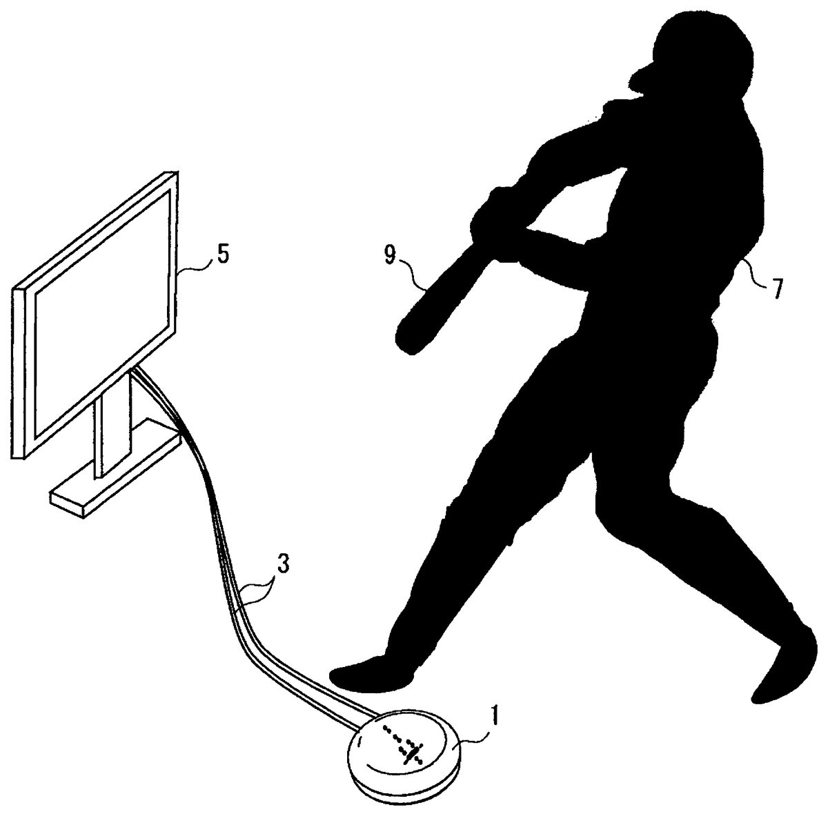
BEST MODE FOR CARRYING OUT THE INVENTION An embodiment of the present invention will now be described in detail with reference to the accompanying drawings.FIG. 1illustrates one scene in which a game apparatus for a virtual or simulation game is used in an embodiment of the present invention as applied to a game apparatus for such a virtual or simulation game. In this figure, a body1of the game apparatus with switches thereof omitted from the illustration is connected directly to a television set5via a cord3, and a game tool9that imitates a bat to be operated (swung) by a player7is used as a part of an input device. FIG. 2is a perspective view of the body1of the game apparatus used in this embodiment.FIG. 3is a cross-sectional view of the body1of the game apparatus, in which most of the internal mechanism is not illustrated. The body1of the game apparatus is provided with a casing15which is constituted by combining an upper half-portion11and a lower half-portion13that are formed by splitting the casing15into two up and down (in a vertical direction). Inside the casing15is disposed a circuit which includes a microcomputer as its principal component. On the surface of the upper half-portion11are arranged four pushbutton switches17to23(that is,17,19,21and23) so that the switches can be pressed down. A sliding-type power switch25is disposed in an area12, of the upper half-portion11, which is surrounded by the four pushbutton switches17to23. These pushbutton switches17to23are operated when making an important selection in the course of the game, such as selection of the game type, pitcher, and repertoire of pitches. In the area12of the upper half-portion11are formed ten through-holes27to36which are paired up two by two. The through-holes27and28, through-holes29and30, through-holes31and32, through-holes33and34, and through-holes35and36are paired respectively. Light-emitting elements39are respectively disposed inside the through-holes27,29,31,33, and35. Light-receiving elements41are respectively disposed inside the through-holes28,30,32,34, and36. In this embodiment ...
BEST MODE FOR CARRYING OUT THE INVENTION
An embodiment of the present invention will now be described in detail with reference to the accompanying drawings.FIG. 1illustrates one scene in which a game apparatus for a virtual or simulation game is used in an embodiment of the present invention as applied to a game apparatus for such a virtual or simulation game. In this figure, a body1of the game apparatus with switches thereof omitted from the illustration is connected directly to a television set5via a cord3, and a game tool9that imitates a bat to be operated (swung) by a player7is used as a part of an input device.
FIG. 2is a perspective view of the body1of the game apparatus used in this embodiment.FIG. 3is a cross-sectional view of the body1of the game apparatus, in which most of the internal mechanism is not illustrated. The body1of the game apparatus is provided with a casing15which is constituted by combining an upper half-portion11and a lower half-portion13that are formed by splitting the casing15into two up and down (in a vertical direction). Inside the casing15is disposed a circuit which includes a microcomputer as its principal component. On the surface of the upper half-portion11are arranged four pushbutton switches17to23(that is,17,19,21and23) so that the switches can be pressed down. A sliding-type power switch25is disposed in an area12, of the upper half-portion11, which is surrounded by the four pushbutton switches17to23. These pushbutton switches17to23are operated when making an important selection in the course of the game, such as selection of the game type, pitcher, and repertoire of pitches. In the area12of the upper half-portion11are formed ten through-holes27to36which are paired up two by two. The through-holes27and28, through-holes29and30, through-holes31and32, through-holes33and34, and through-holes35and36are paired respectively. Light-emitting elements39are respectively disposed inside the through-holes27,29,31,33, and35. Light-receiving elements41are respectively disposed inside the through-holes28,30,32,34, and36. In this embodiment where the game apparatus is used for a simulated baseball game, only the light-emitting elements39disposed inside the through-holes27,28and light-receiving elements41disposed inside the through-holes29,30are actually used for detecting a motion (operation timing) of the game tool9. As shown inFIG. 3, the light-receiving elements41are disposed lower than the light-emitting elements39(in the vicinity of the lower half-portion13). In other words, the vertical length of each of the through-holes28,30,32,34, and36receiving the light-receiving elements41is longer than the vertical length of each of the through-holes27,29,31,33, and35receiving the light-emitting elements39. In view of the light-emitting element39, the shorter the distance of the light-emitting element39and the game tool9equipped with a light-reflecting material is, the more light will be reflected. In view of the light-receiving element41, if the light-receiving element41is disposed too high (if the location thereof is of the same height as the light-emitting element39or higher than that), the light-receiving element41also receives the light other than the light emitted from the light-emitting element39and reflected by the game tool9. Consequently, a signal outputted from the light-receiving element41includes much noise to cause an erroneous detection. A desirable distance in the vertical direction (up and down direction) between the light-receiving element41and the light-emitting element39is varied depending on various factors such as the height of a zone which is located above the body1of the game apparatus and through which the game tool9passes, a quantity of light emitted from the light-emitting element39, an emission angle range of the light emitted from the light-emitting element39(an angular range where the light emitted from the light-emitting element39intersects the zone), a light-receiving angle range (an angular range in which light reflected from the game tool9through the through-holes27,29,31,33, and35can be received) of the light-receiving element41disposed on the bottom of each of the through-holes28,30,32,34, and36, and a reflectance of the light reflecting material disposed on the game tool9. Therefore, how long the above-mentioned distance should be is determined according to design factors. When the light-receiving elements41and the light-emitting elements39are received in the light-receiving element receiving holes28,30,32,34and the light-emitting element receiving holes27,29,31,33respectively, even though the light-receiving elements41and the light-emitting elements39are mounted slightly aslant in the respective holes, the light-receiving element receiving holes28,30and the light-emitting element receiving holes27,29respectively work as a guide for the light, thereby preventing a detection scope from deviating from an originally intended area, and allowing reflected light to be received in the same manner as the light-receiving elements41and light-emitting elements39are mounted in the respective holes without a slant.
FIG. 4is a block diagram showing principal components of a circuit installed inside the body1of the game apparatus according to this embodiment. Power circuits of the light-emitting elements39etc. are omitted from the illustration. What has been developed exclusively for a game apparatus can be applied as a processor43for games having an internal memory42which stores information acquired from a signal outputted from the light-receiving element41. An example of such processor43for games (including a microcomputer) is shown in U.S. Pat. No. 3,467,382, and is publicly known. However, the processor for games used in carrying out the present invention is not limited to what is disclosed in the foregoing patent publication. A program necessary for running the processor43for games is stored in an external memory45. Inside the processor43for games are also included circuits for processing a video signal and an audio signal. Therefore, an output from the processor43for games is outputted directly to a television set. It is needless to say that a circuit may be constructed without using such processor43for games.
FIG. 5is a block diagram showing function-implementing means having various kinds of functions to be implemented inside the processor43for games, and also illustrates the relationship of the light-emitting element39, the light-receiving element41, and the game tool9. The function-implementing means shown inFIG. 5includes motion signal generation means47, operation timing determination means49, image display means55, moving-direction change means51, and motion determination means53. It is needless to say other function-implementing means other than these function-implementing means as described above are used in an actual game apparatus.
The motion signal generation means47includes two light-emitting elements39that emit out light L1in a three dimensional space S in which the game tool9is operated, and two light-receiving elements41which receive reflected light L2emitted from the light-emitting elements39and reflected on the light reflecting material disposed on the surface of the game tool9. InFIG. 5, for ease of understanding, the light L1and the reflected light L2are conveniently illustrated as beams parallel to each other. In this embodiment, one of the light-emitting elements39and one of the light-receiving elements41are used in pairs as previously explained. When the game tool9passes over the body1of the game apparatus, two light receiving signals are respectively outputted with time difference from the two light-receiving elements41,41. The motion signal generation means47generates a motion signal including information on the motion of the game tool9(information on the timing at which the game tool9was swung and the motion speed thereof) based on the two light receiving signals. The motion speed of the game tool9can be known by identifying a time interval between the generation of two light receiving signals. If the two light receiving signals are inputted after a predetermined time interval, or only one light receiving signal is inputted within a predetermined time interval, it can be determined that there has been a swing delay of the game tool9. As well, the operation timing and motion speed as the game tool9is swung can be known from the generation time and generation interval of the two light receiving signals.
The operation timing determination means49determines timing at which the game tool9is swung based on the motion signal as the operation timing at which the input device is operated based on the motion signal and outputs a change command to the moving-direction change means51based on the operation timing.FIG. 6is a flowchart of an example algorithm used in implementing the operation timing determination means49in a computer. In this algorithm, the number of balls available for pitching (the number of remaining pitches) is decremented at the time that a pitcher has pitched a ball (movable object) in the course of the game and the operation timing is determined based on this time point (step ST2). The screen of the television set5displays a movement of the ball in such a manner that the ball is approaching toward the player. After a predetermined time has passed since the pitcher pitched the ball (Step ST21), when a swing is detected (step ST22) and a motion signal is outputted. Details about step ST22in this example is explained later usingFIG. 7. The operation timing is determined based on the motion signal (step ST23). If the operation timing is ahead of predetermined reference timing, a change command to move (hit) the ball (movable object) leftward is outputted (step ST24, ST25). If the operation timing is behind the reference timing, a change command to move (hit) the ball rightward is outputted (step ST26, ST27). Otherwise, namely, when the reference timing and the operation timing coincide with each other, a change command to move (hit) the ball straight toward the pitcher is outputted (step ST28). Incidentally, an advance or delay of the operation timing from the reference timing determines the moving (flying) direction of the ball or an angle of the flying ball with respect to a home base (step ST25, ST27). In this example, it is determined whether or not the ball hits the target at step ST29.
The moving-direction change means51gives a command to the image display means55to output to the television set5a video signal that causes the ball (movable object) to be displayed on the screen as if it is moving (flying) from the pitcher toward the player after the pitcher has pitched the ball (movable object). Upon receipt of the above-mentioned change command from the operation timing determination means49during the movement of the ball, the moving-direction change means51gives a command to the image display means55to output to the television set5a video signal by which the moving (flying) direction of the ball hit by the player is changed in accordance with the change command.
The motion determination means53determines whether or not a predetermined proper motion has been made by the game player with the game tool9in the three dimensional space, based on the motion signal. The image display means55indicates on the screen that the proper motion has been made when the motion determination means53determines that the proper motion has been made by the game player with the game tool9.FIG. 7is a flowchart showing an algorithm of an example of a program when some of the functions of the motion signal generation means47, the motion determination means53and the image display means55are implemented in a computer.
A flowchart ofFIG. 7is explained as follows. During a game, after a ball has been pitched, whether or not the game player swings the game tool9is determined at step ST31according to whether or not reflected light is received. Upon receiving the reflected light, a motion signal is outputted at step ST32. When the motion signal is generated, whether or not the swing motion (the motion of the game tool) is proper is determined based on the motion signal at step ST33. In this embodiment, when both of the two light-receiving elements41receive a light, it is determined “GOOD” (a proper motion has been made). When only one of the light-receiving elements41receives a light, it is determined “NG” (a proper motion has not been made). When “GOOD”, an image of the bat is rotated at step ST34. A subsequent operation for a batted ball is implemented at step ST35. When no reflected light is received within a predetermined time after the pitcher has pitched the ball at step ST35, and when a swing motion is determined “NG”, the image of the bat on the screen is not rotated at step ST37. With this, the game player recognizes there is a problem with the motion of the game tool (a swing of the bat). A part of the functions of the motion signal generation means47inFIG. 5is implemented at step ST31and step ST32in the algorithm ofFIG. 7. The functions of the motion determination means53are implemented at step ST33and step ST36. Furthermore, a part of the functions of the image display means55is implemented at the step ST34and ST37.
FIG. 8shows one example of an initial screen when a target hitting game is implemented with the game apparatus for a virtual or simulation game according to the present invention. On a screen61ofFIG. 8, eight target panels T1to T8are arranged side by side in the play field or mound, four by four on both sides of the pitcher63. In the play field are respectively displayed target holding frame65which holds the four target panels T1to T4and a target holding frame67which holds the other four target panels T5-T8. Ball images68, the number of which corresponds to the number of pitcher's remaining pitches, are displayed in the lower left area of a batter's box on the left side of the screen61. SinceFIG. 8is the initial screen, ten balls' images are displayed as the number of the pitcher's remaining pitches. As well, the bat image69, which is a simulated image of the game tool9, is displayed in the upper right area of the batter's box on the left side of the screen61. The bat image69moves to a position indicated with a broken line to denote that the game tool9has been operated properly by the player, when the motion determination means determines that the game tool9has been operated properly (the game tool9has passed through a predetermined zone above the body1of the game apparatus, or a proper motion signal has been outputted). It can be known from this indication whether or not the position, where the player has swung the game tool9which is a part of the input device, falls within a detection area of a swing detector constituted by the light-emitting elements39and the light-receiving elements41as shown inFIGS. 3 to 5. Therefore, if the bat image does not move even though the player has swung the game tool9within a predetermined time after the pitcher63pitched the ball, the player can then know that the swing position of the game tool9is not proper. With this indication, the player changes the position of the body1of the game apparatus or the standing position of the player.
In the foregoing embodiment, whether or not the game tool9is operated is determined using reflection of light. It is needless to say that various kinds of sensors such as an acceleration sensor can be used for determination of whether or not the game tool9is operated.
In the foregoing embodiment, the present invention is applied to a baseball game. It is needless to say that the present invention can be applied to any games as far as the games are played by hitting a moving movable object with a game tool, such as tennis, badminton, table tennis, and hockey.
In the foregoing embodiment, it is indicated by rotating the bat image69that the game tool has properly been operated. It may be indicated by changing the colors of the bat images that the game tool has properly been operated by changing the colors of the bat image. For example, when an image of a catcher's glove is displayed, it may be indicated by opening or closing the image of the catcher's glove that the game tool has properly been operated.
INDUSTRIAL APPLICABILITY
According to the present invention, the game player can readily recognize that the game tool is not properly operated, based on what is displayed on the screen. Therefore, the game player can carry on the game properly since he/she can be aware of the proper motion of the game tool.
Claims
- A game apparatus for playing a virtual or simulation game comprising: a game tool to be operated by a game player in a three dimensional space;motion signal generation means for detecting a motion of the game tool in the three dimensional space and outputting a motion signal according to the detected motion;image display means having a function of determining a movement of a movable object such as a ball displayed, based on the motion signal, on a screen where no character, which plays on the screen in place of the game player, is displayed;motion determination means for determining, based on the motion signal, whether or not a predetermined proper motion has been made by the player with the game tool in the three dimensional space;operation timing determination means for determining timing at which the game tool is operated as the operation timing based on the motion signal and outputting a change command for changing a moving direction of the movable object based on an advance or delay of the operation timing from a predetermined reference timing;and moving-direction change means for giving a command to the image display means to output a video signal by which the moving direction of the movable object displayed on a screen is changed in accordance with the change command, the image display means further having a function of displaying movement of an imitated image of the game tool on the screen to confirm that the proper motion of the game tool has been made when the motion determination means determines that the proper motion of the game tool has been made and a function of changing the moving direction of the movable object displayed on the screen in accordance with the change command.
- The game apparatus of claim 1 , wherein the motion signal generation means and the image display means are received inside a body of the game apparatus, or the motion signal generation means is received inside the game tool.
- The game apparatus of claim 2 , wherein the game tool is a simulated-sports game tool that imitates sports equipment such as a bat and a racket, or a wearable game tool that is a substitution for a shoe for the player's foot or for a glove for the player's hand;the image display means indicates that the proper motion has been made in a visibly confirmable representation by various ways including changing colors of the imitated image.
- The game apparatus of claim 1 , wherein the motion signal generation means and the image display means are received inside the body of the game apparatus;the game tool has on its surface a light-reflecting material that reflects light;the motion signal generation means includes a light-emitting element that emits out light in the three dimensional space in which the game tool is operated and a light-receiving element that receives reflected light that has been emitted from the light-emitting element and reflected on the light-reflecting material;and the motion signal is generated based on an output from the light-receiving element.
- The game apparatus of claim 4 , wherein a light-emitting element receiving hole for receiving the light-emitting element and a light-receiving element receiving hole for receiving the light-receiving element are disposed at a predetermined interval in a top wall portion of the body of the game tool, the light-receiving element is located lower than the light-emitting element.
Disclaimer: Data collected from the USPTO and may be malformed, incomplete, and/or otherwise inaccurate.