U.S. Pat. No. 9,579,566
VIDEO GAME WITH HELPER ROLE OR OBSTRUCTER ROLE FOR SECOND PLAYER HAVING SEPARATE DISPLAY
AssigneeNintendo Co., Ltd.
Issue DateAugust 5, 2013
Illustrative Figure
Abstract
A main player operates a controller while viewing a monitor game image displayed on a monitor. A sub player operates a terminal device while viewing a terminal game image displayed on an LCD of the terminal device. A game image that is substantially identical to the monitor game image viewed by the main player is displayed on the LCD. By touching a touch panel provided on a screen of the LCD of the terminal device, the sub player can generate various events at a position in a game world corresponding to a touched position.
Description
DETAILED DESCRIPTION OF NON-LIMITING EXAMPLE EMBODIMENTS A game system according to one embodiment will be described with reference toFIG. 1. As shown inFIG. 1, a game system1includes a household television receiver (hereinafter, referred to as a monitor)2which is an example of display means, and a stationary game apparatus3connected to the monitor2via a connection cord. The monitor2includes loudspeakers2a. Furthermore, the game apparatus3includes an optical disc4, a game apparatus body5, a terminal device6, and controllers7a,7b,7c, and7d(hereinafter, described simply as a controller7when there is no particular need to distinguish these as the controllers7a,7b,7c, and7d). The optical disc4has stored therein an information processing program (typically, a game program) to be executed by the game apparatus body5. The monitor2displays a game image outputted from the game apparatus body5. The monitor2includes the loudspeakers2a, and each of the loudspeakers2aoutputs a game sound outputted from the game apparatus body5. The game apparatus body5executes a game process or the like based on a game program stored in the optical disc4. A plurality of operation sections (operation buttons) are provided on the controller7. The controller7transmits, to the game apparatus body5, operation data (controller operation data) representing input states (whether or not each of the operation buttons has been held down) of the operation sections by using, for example, Bluetooth (registered trademark) technology. Furthermore, the controller7includes an imaging section for taking images of a marker8having two LED modules (hereinafter, referred to as “markers”)8L and8R disposed in the vicinity (in the upper side of the screen inFIG. 1) of the display screen of the monitor2, and an imaging information calculation section for calculating positions of the markers within an image taken by the imaging section. The positions of the markers calculated by the imaging information calculation section are transmitted to the game apparatus body5as marker coordinate data. In the game apparatus body5, ...
DETAILED DESCRIPTION OF NON-LIMITING EXAMPLE EMBODIMENTS
A game system according to one embodiment will be described with reference toFIG. 1.
As shown inFIG. 1, a game system1includes a household television receiver (hereinafter, referred to as a monitor)2which is an example of display means, and a stationary game apparatus3connected to the monitor2via a connection cord. The monitor2includes loudspeakers2a. Furthermore, the game apparatus3includes an optical disc4, a game apparatus body5, a terminal device6, and controllers7a,7b,7c, and7d(hereinafter, described simply as a controller7when there is no particular need to distinguish these as the controllers7a,7b,7c, and7d).
The optical disc4has stored therein an information processing program (typically, a game program) to be executed by the game apparatus body5.
The monitor2displays a game image outputted from the game apparatus body5. The monitor2includes the loudspeakers2a, and each of the loudspeakers2aoutputs a game sound outputted from the game apparatus body5.
The game apparatus body5executes a game process or the like based on a game program stored in the optical disc4.
A plurality of operation sections (operation buttons) are provided on the controller7. The controller7transmits, to the game apparatus body5, operation data (controller operation data) representing input states (whether or not each of the operation buttons has been held down) of the operation sections by using, for example, Bluetooth (registered trademark) technology.
Furthermore, the controller7includes an imaging section for taking images of a marker8having two LED modules (hereinafter, referred to as “markers”)8L and8R disposed in the vicinity (in the upper side of the screen inFIG. 1) of the display screen of the monitor2, and an imaging information calculation section for calculating positions of the markers within an image taken by the imaging section. The positions of the markers calculated by the imaging information calculation section are transmitted to the game apparatus body5as marker coordinate data. In the game apparatus body5, the movement, position, attitude, and the like can be calculated by the controller7based on the marker coordinate data.
Furthermore, the controller7is provided with an acceleration sensor and a gyro sensor. Acceleration data representing acceleration detected by the acceleration sensor and angular velocity data representing angular velocity detected by the gyro sensor are transmitted to the game apparatus body5. In the game apparatus body5, directions, movements, and behaviors of the controller7can be calculated based on the acceleration data and/or the angular velocity data.
The terminal device6is a portable device that is small enough to be held by a user, and the user is allowed to move the terminal device6with hands, or place the terminal device6at any location. Although the specific structure of the terminal device6will be described later, the terminal device6includes an LCD (Liquid Crystal Display)61as display means, and input means (a touch panel62, a gyro sensor604, and the like described later). The terminal device6and the game apparatus body5are communicable with each other wirelessly or via a cable. The terminal device6receives, from the game apparatus body5, data of an image (e.g., a game image) generated in the game apparatus body5, and displays the image represented by the data on an LCD61. Although in the exemplary embodiment, an LCD is used as a display device, the terminal device6may include any other display device, such as a display device utilizing EL (Electro Luminescence), for example. Further, the terminal device6transmits, to the game apparatus body5, operation data representing the content of an operation performed on the terminal device6.
Next, with reference toFIG. 2, an internal structure of the game apparatus body5will be described.FIG. 2is a block diagram illustrating an example of an internal structure of the game apparatus body5. The game apparatus body5includes a CPU (Central Processing Unit)10, a system LSI (Large Scale Integration)11, an external main memory12, a ROM/RTC (Read Only Memory/Real Time Clock)13, a disc drive14, an AV-IC (Audio Video-Integrated Circuit)15and the like.
In addition to the CPU10, the external main memory12, the ROM/RTC13, the disc drive14, and the AV-IC15are connected to the system LSI11. The external main memory12, which is a volatile memory, is used as a work region and a buffer region for the CPU10. The ROM/RTC13includes a ROM (so-called boot ROM) incorporating a program for booting the game apparatus body5, and a clock circuit (RTC) for counting time. The disc drive14reads, from the optical disc4, program data, texture data and the like, and writes the read data into an internal main memory35described below or the external main memory12.
The system LSI11includes an input/output processor (I/O processor)31, a GPU (Graphics Processor Unit)32, a DSP (Digital Signal Processor)33, a VRAM (Video RAM)34, and the internal main memory35.
The GPU32generates an image in accordance with a graphics command (draw command) supplied from the CPU10. In the exemplary embodiment, the game apparatus body5may generate both a game image to be displayed on the monitor2and a game image to be displayed on the terminal device6. Hereinafter, the game image to be displayed on the monitor2may be referred to as a “monitor game image,” and the game image to be displayed on the terminal device6may be referred to as a “terminal game image.”
The DSP33, serving as an audio processor, generates sound data by using sound data and sound waveform (tone quality) data stored in the internal main memory35and the external main memory12. In the exemplary embodiment, similarly to the game images, both a game sound to be outputted from the loudspeakers2aof the monitor2and a game sound to be outputted from the loudspeakers of the terminal device6may be generated. Hereinafter, the game sound to be outputted from the monitor2may be referred to as a “monitor game sound,” and the game sound to be outputted from the terminal device6may be referred to as a “terminal game sound.”
Among the image data and sound data generated by the game apparatus body5, the image data and sound data to be outputted to the monitor2are read by the AV-IC15. Through an AV connector16, the AV-IC15outputs the read image data to the monitor2and outputs the read sound data to the loudspeakers2aincluded in the monitor2. Thereby, an image is displayed on the monitor2, and sounds are outputted from the loudspeakers2a.
Further, among the image data and sound data generated by the game apparatus body5, the image data and sound data to be outputted to the terminal device6are transmitted to the terminal device6by the I/O processor31or the like. Data transmission to the terminal device6by the I/O processor31or the like will be described later.
The I/O processor31executes data reception and transmission with the components connected thereto, and download of data from an external apparatus. The I/O processor31is connected to a flash memory17, a network communication module18, a controller communication module19, an extension connector20, a memory card connector21, and a codec LSI27. The codec LSI27is connected to a terminal communication module28.
The game apparatus body5is connected to a network such as the Internet so as to communicate with external information processing apparatuses (for example, other game apparatuses or various servers). That is, the I/O processor31is connected to a network via the network communication module18and the antenna22so as to communicate with external information processing apparatuses connected to the network. The flash memory17may store not only the data transmitted and received between the game apparatus body5and the external information processing apparatuses, but also saved data (result data or progress data of the process) of the game played with the game apparatus body5. Further, the flash memory17may store programs such as a game program.
The game apparatus body5can receive operation data from the controller7. That is, the I/O processor31receives, via the antenna23and the controller communication module19, operation data or the like transmitted from the controller7, and stores (temporarily) the data in a buffer region of the internal main memory35or the external main memory12.
The game apparatus body5is capable of transmitting/receiving image data, sound data and the like to/from the terminal device6. The I/O processor31outputs data of a game image (terminal game image) generated by the GPU32to the codec LSI27. The codec LSI27performs a predetermined compression process on the image data supplied from the I/O processor31. The terminal communication module28performs wireless communication with the terminal device6. Accordingly, the image data compressed by the codec LSI27is transmitted by the terminal communication module28to the terminal device6via an antenna29. In the exemplary embodiment, the codec LSI27compresses the image data by using a highly efficient compression technique, for example, the H.264 standard. The codec LSI27may adopt other compression techniques. When the communication rate is sufficiently high, uncompressed image data may be transmitted. The terminal communication module28is, for example, a Wi-Fi certified communication module. The terminal communication module28may perform wireless communication with the terminal device6at a high speed by using, for example, the technique of MIMO (Multiple Input Multiple Output) adopted in the IEEE802.11n standard, or may use other communication techniques.
The game apparatus body5transmits, to the terminal device6, sound data as well as the image data. That is, the I/O processor31outputs sound data (terminal game sound) generated by the DSP33to the terminal communication module28via the codec LSI27. The codec LSI27performs a compression process on the sound data in a manner similar to that for the image data. Any compression technique may be adopted for the sound data. In another embodiment, uncompressed sound data may be transmitted. The terminal communication module28transmits the compressed image data and sound data to the terminal device6via the antenna29.
The game apparatus body5transmits, in addition to the image data and sound data, various control data to the terminal device6, according to need. The control data represent control instructions for the components included in the terminal device6, such as an instruction to control on/off of a marker section (a marker section65shown inFIG. 5), and an instruction to control image taking of a camera (a camera66shown inFIG. 5). The I/O processor31transmits the control data to the terminal device6in response to an instruction from the CPU10.
The game apparatus body5can receive various data from the terminal device6. Although details will be described later, in the exemplary embodiment, the terminal device6transmits operation data, image data, and sound data. The respective data transmitted from the terminal device6are received by the terminal communication module28via the antenna29. The image data and sound data transmitted from the terminal device6have been subjected to a compression process similar to that for the image data and sound data transmitted from the game apparatus body5to the terminal device6. Accordingly, these image data and sound data are transmitted from the terminal communication module28to the codec LSI27, and subjected to a decompression process by the codec LSI27. The decompressed data are outputted to the I/O processor31. The operation data, which has been received by the terminal communication module28, is outputted to the I/O processor31via the codec LSI27. The I/O processor31stores (temporarily) the data received from the terminal device6in the buffer region of the internal main memory35or the external main memory12.
The game apparatus body5is connectable to other devices and external storage media via the extension connector20and the memory card connector21.
The game apparatus body5includes (on the front main surface thereof, for example) a power button24, a reset button25, an insertion slot through which the optical disc4is inserted, an eject button26for ejecting the optical disc4from the insertion slot of the game apparatus body5, and the like.
In another embodiment, some of the components of the game apparatus body5may be constituted as an extension device separated from the game apparatus body5. At this time, the extension device may be connected to the game apparatus body5via the extension connector20, for example. Specifically, the extension device may include, for example, the codec LSI27, the terminal communication module28, and the antenna29, and may be detachably connected to the extension connector20. Thus, by connecting the extension device to the game apparatus body which does not have the above-mentioned, the game apparatus body can be made communicable with the terminal device6.
Next, a structure of the terminal device6will be described with reference toFIG. 3toFIG. 5.FIG. 3is a diagram illustrating an example of an external structure of the terminal device6. More specifically, (a) ofFIG. 3is a front view, (b) ofFIG. 3is a top view, (c) ofFIG. 3is a right side view, and (d) ofFIG. 3is a bottom view of the terminal device6.FIG. 4shows an example of a state in which a user holds the terminal device6with both hands.
As shown inFIG. 3, the terminal device6includes a housing60which generally has a horizontally long plate-like rectangular shape. The housing60is small enough to be held by the user.
The terminal device6includes the LCD61on a front surface of the housing60. The LCD61is provided near the center of the front surface of the housing60. Therefore, as shown inFIG. 4, the user, holding the housing60at portions to the right and left of the LCD61, is allowed to move the terminal device6while viewing a screen of the LCD61.
As shown in (a) ofFIG. 3, the terminal device6includes, as operation means, a touch panel62on the screen of the LCD61. In the exemplary embodiment, the touch panel62is, but is not limited to, a resistive film type touch panel, and a touch panel of any type, such as electrostatic capacitance type, may be used. The touch panel62may be of single touch type or multiple touch type. In the exemplary embodiment, the touch panel62has the same resolution (detection accuracy) as that of the LCD61. However, the resolution of the touch panel62and the resolution of the LCD61need not be the same. Since the terminal device6has the touch panel62, the user is allowed to operate the touch panel62while moving the terminal device6. That is, the user is allowed to directly (by using the touch panel62) perform an input onto the screen of the LCD61while moving the LCD61.
As shown inFIG. 3, the terminal device6has, as operation means, two analog sticks63A and63B, and a plurality of operation buttons64A to64L. The analog sticks63A and63B are each a device for designating a direction. The analog sticks63A and63B are each configured such that a stick part thereof to be operated by a finger of the user is slidable or tiltable in any direction (at any angle in any direction such as the upward, the downward, the rightward, the leftward, or the diagonal direction) with respect to the front surface of the housing60.
The respective operation buttons64A to64L are assigned functions, according to need, in accordance with a game program. For example, the cross button64A may be used for direction designation operation, selection operation, and the like; and the operation buttons64E to64H may be used for determination operation, cancellation operation, and the like.
As shown in (a) ofFIG. 3, the terminal device6includes a marker section (the marker section65shown inFIG. 5) including a marker65A and a marker65B, on the front surface of the housing60. The markers65A and65B are each constituted by one or more infrared LEDs. The marker section65is used, like the marker8, for causing the game apparatus body5to calculate a movement or the like of the controller7with respect to the marker section65. The game apparatus body5is capable of controlling the infrared LEDs of the marker section65to be turned on or off.
The terminal device6includes the camera66. The camera66is disposed on the surface of the housing60. Accordingly, the camera66is capable of taking an image of the face of the user holding the terminal device6. For example, the camera66can take an image of the user who is playing a game while viewing the LCD61.
The terminal device6has a microphone (a microphone609shown inFIG. 5) as sound input means. The microphone609is embedded in the housing60at a position inside the microphone hole60b. The microphone609detects for a sound, such as user's voice, around the terminal device6.
The terminal device6has loudspeakers (loudspeakers607shown inFIG. 5). Sound from the loudspeakers607is outputted from loudspeaker holes60aprovided on the lower side surface of the housing60.
The terminal device6includes an extension connector67for connecting other devices to the terminal device6.
In the terminal device6shown inFIG. 3, the shapes of the operation buttons and the housing60, the number of the respective components, and the positions in which the components are provided are merely examples. The shapes, numbers, and positions may be different from those described above.
Next, an internal structure of the terminal device6will be described with reference toFIG. 5.FIG. 5is a block diagram illustrating an example of an internal structure of the terminal device6. As shown inFIG. 5, the terminal device6includes, in addition to the components shown inFIG. 3, a touch panel controller601, a magnetic sensor602, an acceleration sensor603, the gyro sensor604, a user interface controller (UI controller)605, a codec LSI606, loudspeakers607, a sound IC608, a microphone609, a wireless module610, an antenna611, an infrared communication module612, a flash memory613, a power supply IC614, a battery615, and a vibrator619. These electronic components are mounted on an electronic circuit board and accommodated in the housing60.
The UI controller605is a circuit for controlling data input to various input/output sections and data output from various input/output sections. The UI controller605is connected to the touch panel controller601, an analog stick63(the analog sticks63A and63B), the operation button64(the operation buttons64A to64L), the marker section65, the magnetic sensor602, the acceleration sensor603, the gyro sensor604, and the vibrator619. Further, the UI controller605is connected to the codec LSI606and the extension connector67. The power supply IC614is connected to the UI controller605, so that power is supplied to the respective components through the UI controller605. The internal battery615is connected to the power supply IC614, so that power is supplied from the battery615. Further, a battery charger616or a cable, which is supplied with power from an external power supply, may be connected to the power supply IC614via a connector or the like. In this case, the terminal device6can be supplied with power and charged from the external power supply by using the battery charger616or the cable.
The touch panel controller601is a circuit which is connected to the touch panel62and controls the touch panel62. The touch panel controller601generates a predetermined form of touch position data, based on a signal from the touch panel62, and outputs the touch position data to the UI controller605. The touch position data represents coordinates of a position at which an input is performed on an input surface of the touch panel62. The touch panel controller601reads a signal from the touch panel62and generates touch position data every predetermined period of time. Further, various control instructions are outputted from the UI controller605to the touch panel controller601.
The analog stick63outputs, to the UI controller605, stick data representing an amount and direction of the sliding (or tilting) of the stick part. The operation button64outputs, to the UI controller605, operation button data representing an input status of each of the operation buttons64A to64L (whether or not the operation button is pressed).
The magnetic sensor602detects the magnitude and direction of a magnetic field to detect an orientation. Orientation data representing the detected orientation is outputted to the UI controller605. The UI controller605outputs, to the magnetic sensor602, a control instruction for the magnetic sensor602. Examples of the magnetic sensor602include: an MI (Magnetic Impedance) sensor, a fluxgate sensor, a Hall sensor, a GMR (Giant Magneto Resistance) sensor, a TMR (Tunneling Magneto Resistance) sensor, and an AMR (Anisotropic Magneto Resistance) sensor. However, any sensor may be adopted as long as the sensor can detect an orientation.
The acceleration sensor603is provided inside the housing60. The acceleration sensor603detects the magnitudes of linear accelerations in all three axial directions (xyz axial directions shown in (a) ofFIG. 3). Acceleration data representing the detected accelerations is outputted to the UI controller605. The UI controller605outputs, to the acceleration sensor603, a control instruction for the acceleration sensor603.
The gyro sensor604is provided inside the housing60. The gyro sensor604detects the angular velocities around all the three axes (the above-described xyz axes). Angular velocity data representing the detected angular velocities is outputted to the UI controller605. The UI controller605outputs, to the gyro sensor604, a control instruction for the gyro sensor604.
The vibrator619is, for example, a vibration motor or a solenoid, and the terminal device6is vibrated by actuating the vibrator619in accordance with a control instruction outputted from the UI controller605to the vibrator619.
The UI controller605outputs, to the codec LSI606, the operation data (hereinafter, referred to as terminal operation data) including the touch position data, the stick data, the operation button data, the orientation data, the acceleration data and the angular velocity data, which have been received from the respective components.
The codec LSI606is a circuit for performing a compression process on data to be transmitted to the game apparatus body5, and a decompression process on data transmitted from the game apparatus body5. The LCD61, the camera66, the sound IC608, the wireless module610, the flash memory613, and the infrared communication module612are connected to the codec LSI606. The codec LSI606includes a CPU617and an internal memory618. Although the terminal device6is configured not to perform a game process, the terminal device6may execute a program for managing the terminal device6or a program for communication. For example, a program stored in the flash memory613is loaded into the internal memory618and executed by the CPU617when the terminal device6is powered on, thereby starting up the terminal device6. A part of the area of the internal memory618is used as a VRAM for the LCD61.
The camera66takes an image in accordance with an instruction from the game apparatus body5, and outputs data of the taken image to the codec LSI606. The codec LSI606outputs, to the camera66, a control instruction for the camera66, such as an instruction to take an image. The camera66is also capable of taking a moving picture. That is, the camera66is capable of repeatedly performing image taking, and repeatedly outputting image data to the codec LSI606.
The sound IC608is a circuit for controlling input of sound data to the microphone609and output of sound data from the loudspeakers607.
The codec LSI606transmits the image data from the camera66, the sound data from the microphone609, and the terminal operation data from the UI controller605to the game apparatus body5via the wireless module610. In the exemplary embodiment, the codec LSI606subjects the image data and the sound data to a compression process similar to that performed by the codec LSI27. The compressed image data and sound data, and the terminal operation data are outputted to the wireless module610as transmission data. The antenna611is connected to the wireless module610, and the wireless module610transmits the transmission data to the game apparatus body5through the antenna611. The wireless module610has the same function as the terminal communication module28of the game apparatus body5. That is, the wireless module610has a function of connecting to a wireless LAN by a method based on, for example, the IEEE802.11n standard.
As described above, the transmission data transmitted from the terminal device6to the game apparatus body5includes the terminal operation data, the image data, and the sound data. If another device is connected to the terminal device6through the extension connector67, data received from the other device may be included in the transmission data. The infrared communication module612performs, with another device, infrared communication based on, for example, the IRDA standard. The codec LSI606may include, in the transmission data, data received by the infrared communication, and transmit the transmission data to the game apparatus body5, according to need.
As described above, the compressed image data and sound data are transmitted from the game apparatus body5to the terminal device6. These data are received by the codec LSI606through the antenna611and the wireless module610. The codec LSI606decompresses the received image data and sound data. The decompressed image data is outputted to the LCD61, and an image according to the image data is displayed on the LCD61. On the other hand, the decompressed sound data is outputted to the sound IC608, and a sound based on the sound data is outputted from the loudspeakers607.
When control data is included in the data received from the game apparatus body5, the codec LSI606and the UI controller605provide control instructions for the respective components, according to the control data. As described above, the control data represents control instructions for the respective components (in the exemplary embodiment, the camera66, the touch panel controller601, the marker section65, the sensors602to604, the vibrator619, and the infrared communication module612) included in the terminal device6. In the exemplary embodiment, the control instructions represented by the control data are considered to be instructions to start and halt (stop) the operations of the above-mentioned components. That is, some components which are not used for a game may be halted to reduce power consumption. In this case, data from the halted components are not included in the transmission data transmitted from the terminal device6to the game apparatus body5.
Next, one example of a game executed the game system of the exemplary embodiment will be described with reference toFIG. 6toFIG. 18.
An objective of this game for a player is to operate the controller7and to control a player character to reach a goal point in a game world (a two dimensional virtual space) as shown inFIG. 6.
As shown inFIG. 6, for example, a player character P1, an enemy character E1, a normal block NB, an item block IB, and the like exist in the game world.
The player character P1is a character that is to be controlled by the player. The enemy character E1is controlled by a computer based on a predetermined algorithm.
A normal block NB can be used as a foothold for the player character P1. By hitting a normal block NB from below, the player character P1can destroy the normal block NB.
The appearance of an item block IB is same as a normal block NB, but is a block that has some kind of item (e.g., an item that allows the player character P1to be in an invincible state for a predetermined period of time) hidden therein. An item hidden in the item block IB emerges when the player character P1hits the item block IB from below.
In this game, while one or more players (main player(s)) are playing the game by controlling respective player characters by using the respective controllers7, another player (sub player) can assist the main player(s) by generating various events in the game world by using the terminal device6. In the following, an assisting operation by the sub player through a use of the terminal device6will be specifically described.
FIG. 7shows one example of a monitor game image displayed on the monitor2when a certain player (hereinafter, referred to as a player A) is playing the game by using a controller7ato control the player character P1. The main player operates the controller7while viewing the monitor game image displayed on the monitor2.
FIG. 8shows a terminal game image displayed on the LCD61of the terminal device6at the same time when the monitor game image inFIG. 7is displayed on the monitor2. The sub player operates the terminal device6while viewing the terminal game image displayed on the LCD61.
As it is obvious whenFIG. 7andFIG. 8are compared, a game image that is substantially identical to the monitor game image viewed by the main player is displayed on the LCD61. More specifically, an image of the same game world viewed from the same direction is displayed on the monitor game image and the terminal game image, and a display range of the game world displayed in the monitor game image and a display range of the game world displayed in the terminal game image are nearly the same.
The difference between the monitor game image inFIG. 7and the terminal game image inFIG. 8is that an item hidden in an item block IB is not displayed in the monitor game image whereas the item hidden in the item block IB is displayed in the terminal game image. As a result, the main player does not know which item is hidden in which block until a block is hit from below. However, the sub player knows in advance which item is hidden in which block. In addition, an arrow HP indicating a hidden passage (a passage that cannot be viewed on the monitor game image) is displayed on the terminal game image.
By touching the touch panel62of the terminal device6, the sub player can generate various events at a position corresponding to the touched position in the game world. For example, when nothing exists at the position in the game world corresponding to the touched position, a new normal block NB can be placed at that position. In another embodiment, a block that is different from a normal block NB may be placed. Furthermore, when the enemy character exists at the position in the game world corresponding to the touched position, the movement of the enemy character can be stopped. In addition, when a normal block NB exists at the position in the game world corresponding to the touched position, that normal block NB can be destroyed.
For example, in order to allow the player character P1to obtain an item hidden in an item block IB, the sub player can place a new normal block NB by touching a position below the item block IB where there are no other objects as shown inFIG. 9. When the sub player places a new normal block NB in the game world, the normal block NB will also appear in the monitor game image viewed by the main player as shown inFIG. 10. As a result, the main player can use that normal block NB as a foothold and have the item hidden in the item block IB appear as shown inFIG. 11.
FIG. 12shows a monitor game image obtained when the player character P1has advanced slightly toward the goal point from the state inFIG. 11. As can be understood from the figure, the game world displayed in the monitor2has been scrolled as a result of the player character P1advancing toward the goal point. Furthermore,FIG. 13shows a terminal game image displayed on the LCD61of the terminal device6at the same time point when the monitor game image inFIG. 12is displayed on the monitor2.
InFIG. 12andFIG. 13an enemy character E2is approaching the player character P1. Here, in order to assist the main player, the sub player touches the enemy character E2as shown inFIG. 13, and the movement of the enemy character E2stops as shown inFIG. 14.
Instead of assisting the main player, the sub player can also obstruct the main player. For example, the sub player can obstruct the player character P1from escaping toward the left direction by placing a new normal block NB at a position show inFIG. 15.
In such manner, in this game, the sub player can assist or obstruct the progress of the game played by the main player, by touching a desired position in the game world displayed in the LCD61and generating a predetermined event at the touched position.
As shown inFIG. 7toFIG. 15, although the display range of the game world displayed in the terminal game image and the display range of the game world displayed in the monitor game image are basically identical, these display ranges can be shifted from the other.
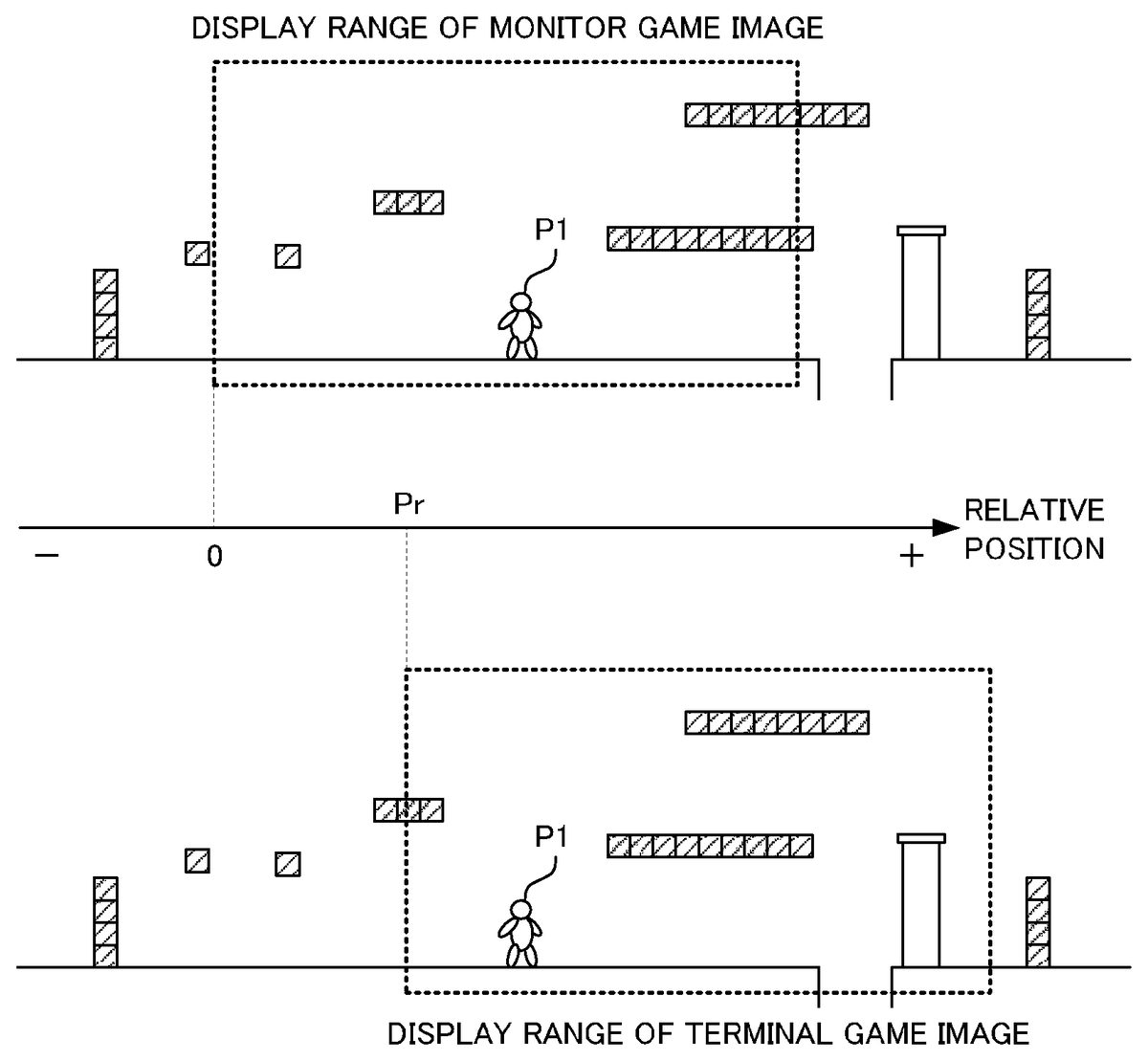
For example, as shown inFIG. 16, the display range of the game world displayed in the terminal game image may be set forward (i.e., in a direction toward the goal point) by a distance Pr from the display range of the game world displayed in the monitor game image. As a result, displayed on the LCD61is a range (as seen inFIG. 18) slightly in front of a range (as seen inFIG. 17) displayed on the monitor2, and the sub player can view the game world ahead of the main player and provide assistance such as installing a normal block NB that can be used as a foothold.
In the exemplary embodiment, by moving the terminal device6in the right or left direction, the sub player can change a relative position (i.e., the value of Pr shown inFIG. 16) of a display range of the game world displayed in the terminal game image with respect to a display range of the game world displayed in the monitor game image. Specifically, with respect to a display range of the game world displayed in the monitor game image, when the terminal device6is moved rightward, the relative position of the display range of the game world displayed in the terminal game image shifts in the rightward direction (i.e., the direction toward the goal point), and when the terminal device6is moved leftward, the relative position shifts in the leftward direction (i.e., the direction toward the starting point). The movement of the terminal device6can be detected by, for example, the acceleration sensor603.
Next, detailed action of the game system to achieve the game will be described with reference toFIG. 19toFIG. 22.
FIG. 19shows one example of various data stored in the external main memory12of the game apparatus body5when the game is executed.
A game program D1is a program that causes the CPU10of the game apparatus body5to execute a game process for achieving the game. The game program D1is loaded, for example, from the optical disc4to the external main memory12.
Game world information D2is information that defines the game world. The game world information D2includes, for example, information regarding positions, attitudes, conditions, and the like of various objects (player characters, enemy characters, normal blocks, item blocks, items, and the like) in the game world, information regarding images and the like, and information regarding background images. In the exemplary embodiment, the game world is a two dimensional virtual space, and thereby positions of various objects in the game world are represented by, for example, two-dimensional coordinates of a world coordinate system shown inFIG. 6.
Controller operation data D3is operation data that is periodically transmitted from the controller7. When multiple main players are to simultaneously play the game by using multiple controllers7among the controllers7a,7b,7c, and7d; controller operation data from the multiple controllers7are stored in the external main memory12so as to be distinguishable from each other.
Terminal operation data D4is operation data that is periodically transmitted from the terminal device6. As described above, the terminal operation data D4includes the touch position data, the acceleration data, and the like.
Display range information D5of the monitor game image is information representing a display range of a game world displayed in the monitor game image. The display range information D5of the monitor game image is represented, for example, by an X coordinate value in the world coordinate system shown inFIG. 6.
Relative position information D6is information representing a relative position of a display range of the game world displayed in the terminal game image with respect to a display range of the game world displayed in the monitor game image. The relative position information D6is represented, for example, by a value of Pr shown inFIG. 16.
Display range information D7of the terminal game image is information representing a display range of the game world displayed in the terminal game image. The display range information D7of the terminal game image is represented, for example, by an X coordinate value in the world coordinate system shown inFIG. 6.
Next, a flow of the game process executed by the CPU10of the game apparatus body5based on the game program D1will be described with reference to flowcharts inFIG. 20toFIG. 22.
When execution of the game program D1is initiated, first, at step S10inFIG. 20, the CPU10sets up initial settings. In the initial settings, a process for setting a position of a player character to an initial position, processes for setting, to initial values, the display range information D5of the monitor game image, the relative position information D6, and the display range information D7of the terminal game image, and the like are conducted.
At step S11, the CPU10acquires the terminal operation data D4from the terminal device6.
At step S12, the CPU10executes an event generating process. In the following, details of the event generating process will be described with reference to the flowchart inFIG. 21.
When the event generating process is initiated, first, at step S20, the CPU10converts the touch position data included in the terminal operation data D4into world coordinates. The conversion is conducted based on the display range information D7of the terminal game image. With this, a position in the game world corresponding to a position on the LCD61where the sub player has touched is determined.
At step S21, the CPU10compares the world coordinates obtained through the conversion at step S20to position information of each object included in the game world information D2, and determines whether the sub player has touched a position in the game world where there are no other objects (i.e., a position absent of various objects such as player characters, enemy characters, normal blocks, and the like). If it is determined that the sub player has touched a position in the game world where there are no other objects, the process advances to step S22; otherwise, the process advances to step S23.
At step S22, the CPU10arranges a new normal block NB at the position in the game world where the sub player has touched (i.e., the position in the game world indicated by the world coordinates obtained through the conversion at step S20). Thus, information regarding the new normal block NB is added to the game world information D2.
At step S23, the CPU10compares the world coordinates obtained through the conversion at step S20to position information of each enemy character included in the game world information D2, and determines whether any of the enemy characters has been touched. If it is determined that the sub player has touched any of the enemy characters, the process advances to step S24; otherwise, the process advances to step S25.
At step S24, the CPU10stops an enemy character that has been touched by the sub player. More specifically, the information representing the state of the enemy object included in the game world information D2is changed from a normal state to a stopped state.
At step S25, the CPU10compares the world coordinates obtained through the conversion at step S20to position information of each normal block NB included in the game world information D2, and determines whether the sub player has touched any of the normal blocks NB. If it is determined that the sub player has touched any of the normal blocks NB, the process advances to step S26; otherwise, the event generating process ends.
At step S26, the CPU10destroys a normal block NB that has been touched by the sub player. More specifically, the information representing the normal block NB included in the game world information D2is deleted. Then the event generating process ends.
When the event generating process ends, the process advances to step S13inFIG. 20.
At step S13, the CPU10acquires the controller operation data D3from the controller7.
At step S14, the CPU10controls a player character based on the controller operation data D3. Specifically, information (position, attitude, state) regarding the player character included in the game world information D2are changed based on the controller operation data D3.
At step S15, the CPU10controls enemy characters etc., in accordance with a predetermined algorithm. Specifically, information (position, attitude, state) regarding the enemy characters included in the game world information D2are changed in accordance with the predetermined algorithm.
At step S16, the CPU10executes a display range update process. In the display range update process, the display range of the game world displayed in the monitor game image and the display range of the game world displayed in the terminal game image are each updated. In the following, details of the display range update process will be described with reference to the flowchart inFIG. 22.
When the display range update process is initiated, first, at step S30, the CPU10updates the display range of the game world displayed in the monitor game image based on the current position of the player character. More specifically, the display range information D5of the monitor game image is updated based on position information of the player character included in the game world information D2. When multiple player characters exist in the game world, the display range information D5of the monitor game image is updated based on position information of the multiple player characters.
At step S31, the CPU10determines whether the terminal device6has moved in the rightward direction based on the acceleration data included in the terminal operation data D4. If the terminal device6is determined to have moved in the rightward direction, the process advances to step S32; otherwise, the process advances to step S33.
At step S32, the CPU10shifts, to the rightward direction (i.e., the direction toward the goal point), the relative position of the display range in the game world displayed in the terminal game image with respect to the display range of the game world displayed in the monitor game image. Specifically, a value of the relative position information D6is increased in accordance with an amount of movement of the terminal device6in the rightward direction. Then, the process advances to step S35.
At step S33, the CPU10determines whether the terminal device6has moved in the leftward direction based on the acceleration data included in the terminal operation data D4. Then, if the terminal device6is determined to have moved in the leftward direction, the process advances to step S34; otherwise, the process advances to step S35.
At step S34, the CPU10shifts, to the leftward direction (i.e., the direction toward the starting point), the relative position of the display range in the game world displayed in the terminal game image with respect to the display range of the game world displayed in the monitor game image. Specifically, the value of the relative position information D6is reduced in accordance with the amount of movement of the terminal device6in the leftward direction. Then, the process advances to step S35.
At step S35, the CPU10updates the display range of the terminal game image based on the relative position information D6and the display range information D5of the monitor game image (i.e., updates the display range information D7of the terminal game image). Then, the display range update process ends.
When the display range update process ends, the process advances to step S17inFIG. 20.
At step S17, the CPU10generates a monitor game image based on the display range information D5of the monitor game image and the game world information D2. The generated monitor game image is outputted from the game apparatus body5to the monitor2, and displayed on the monitor2. One portion or all of the processes for generating the monitor game image may be conducted on the GPU32in accordance with an instruction form the CPU10.
At step S18, the CPU10generates a terminal game image based on the display range information D7of the terminal game image and the game world information D2. The generated terminal game image is outputted from the game apparatus body5to the terminal device6, and displayed on the LCD61of the terminal device6. One portion or all of the processes for generating the terminal game image may be conducted on the GPU32in accordance with an instruction from the CPU10.
A specific object (e.g., the item block IB shown inFIG. 7andFIG. 8) may have different display modes in the monitor game image generated at step S17and in the terminal game image generated at step S18. Furthermore, for example, menu icons Ia, Ib, and Ic for the sub player may be displayed only on the terminal game image as shown inFIG. 23.
As described above, in the exemplary embodiment, the same game world is displayed on the monitor2viewed by the main player and on the LCD61viewed by the sub player, and a predetermined event is generated at a position in the game world instructed by the sub player using the touch panel62. Therefore, the sub player can assist and/or obstruct the main player.
Furthermore, in the exemplary embodiment, since a screen (the monitor2) viewed by the main player and a screen (the LCD61) viewed by the sub player are different, there is no need to display, on the monitor game image, a pointer or a cursor used by the sub player to point a desired position in the game world, and there is no need for the sub player to touch the monitor game image to point a desired position in the game world. Therefore, pointing a desired position in the game world by the sub player can be conducted without disturbing visibility of the monitor game image.
Furthermore, in the exemplary embodiment, since pointing a desired position in the game world by the sub player is conducted by using the touch panel62, the desired position can be pointed simply and easily.
Furthermore, in the exemplary embodiment, since a substantially identical game image is displayed on the screen (the monitor2) viewed by the main player and on the screen (the LCD61) viewed by the sub player, the sub player and the main player can obtain a sensation of playing the same game together.
Furthermore, in the exemplary embodiment, since scrolling of the terminal game image is conducted automatically in accordance with scrolling of the monitor game image, there is no need for the sub player to manually scroll the terminal game image so as to chase the player character.
Furthermore, in the exemplary embodiment, since the sub player can change the relative position of the display range of the game world displayed in the terminal game image with respect to the display range of the game world displayed in the monitor game image, the sub player can change the relative position as appropriate in order to allow easy operation for himself/herself.
Furthermore, since the relative position can be changed by moving the terminal device60, the sub player can simply and intuitively change the relative position.
Furthermore, in the exemplary embodiment, both images of the monitor game image and the terminal game image are generated by the game apparatus body5based on the identical game world information D2. Therefore, there is no possibility of any inconsistencies in the two game images; unlike a case where the two game images are individually generated in different information processing apparatuses, such as, for example, when the monitor game image is generated by the game apparatus body5and the terminal game image is generated by the terminal device6.
Furthermore, in the exemplary embodiment, since the sub player can assist and/or obstruct the main player by using the portable terminal device6, the sub player can operate the terminal device6outside a field of view of the main player. Therefore, the sub player can surprise the main player by generating an event in the game world without being anticipated by the main player beforehand.
It is to be noted that the above described embodiment is merely one example.
For example, although the game world is a two dimensional virtual space in the above described embodiment, the game world may be a three dimensional virtual space in another embodiment.
Furthermore, although the relative position of the display range of the terminal game image changes with respect to the display range of the monitor game image in accordance with a movement of the terminal device6in the rightward or leftward direction in the above described embodiment, in another embodiment, the relative position may change in accordance with any movement (e.g., rotation, and the like) of the terminal device6. Furthermore, in still another embodiment, the relative position may be changed by the operation button64provided on the terminal device6.
Furthermore, in the above described embodiment, although the multiple processes shown inFIG. 20toFIG. 22are executed on a single computer (the CPU10), in another embodiment, these multiple processes may be distributed and executed on multiple computers. Furthermore, in still another embodiment, one portion of these multiple processes may be achieved through hardware circuitry.
Furthermore, in the above described embodiment, although the multiple processes shown inFIG. 20toFIG. 22are executed on a single information processing apparatus (the game apparatus body5), in another embodiment, these multiple processes may be distributed and executed on multiple information processing apparatuses (e.g., the game apparatus body5and a server device).
Furthermore, in the above described embodiment, although the game program D1is provided to the game apparatus body5from the optical disc4, in another embodiment, the game program D1may be provided to the game apparatus body5from any other computer readable storage media (e.g., CD-ROM, semiconductor memory, and the like). Furthermore, in still another embodiment, the game program D1may be stored in advance in a nonvolatile memory (the ROM/RTC13, the flash memory17) inside the game apparatus body5. Furthermore, in still another embodiment, the game program D1may be transmitted to the game apparatus body5from another information processing apparatus (game apparatus, server device).
The systems, devices and apparatuses described herein may include one or more processors, which may be located in one place or distributed in a variety of places communicating via one or more networks. Such processor(s) can, for example, use conventional 3D graphics transformations, virtual camera and other techniques to provide appropriate images for display. By way of example and without limitation, the processors can be any of: a processor that is part of or is a separate component co-located with the stationary display and which communicates remotely (e.g., wirelessly) with the movable display; or a processor that is part of or is a separate component co-located with the movable display and communicates remotely (e.g., wirelessly) with the stationary display or associated equipment; or a distributed processing arrangement some of which is contained within the movable display housing and some of which is co-located with the stationary display, the distributed portions communicating together via a connection such as a wireless or wired network; or a processor(s) located remotely (e.g., in the cloud) from both the stationary and movable displays and communicating with each of them via one or more network connections; or any combination or variation of the above.
The processors can be implemented using one or more general-purpose processors, one or more specialized graphics processors, or combinations of these. These may be supplemented by specifically-designed ASICs (application specific integrated circuits) and/or logic circuitry. In the case of a distributed processor architecture or arrangement, appropriate data exchange and transmission protocols are used to provide low latency and maintain interactivity, as will be understood by those skilled in the art.
Similarly, program instructions, data and other information for implementing the systems and methods described herein may be stored in one or more on-board and/or removable memory devices. Multiple memory devices may be part of the same device or different devices, which are co-located or remotely located with respect to each other.
While certain exemplary embodiments has been described in detail, the foregoing description is in all aspects illustrative and not restrictive. It will be understood that numerous other modifications and variations can be devised.
Claims
- A non-transitory computer-readable storage medium having stored thereon a game program executed by a computer of a game apparatus for conducting a game process in accordance with (a) an input from a portable display device including a touch panel and a display, and (b) an input from at least one input device, the computer being caused to function as: a first input receiver configured to receive an input from the touch panel, a second input receiver configured to receive an input from the at least one input device;a game processor configured to conduct a predetermined game process based on an input received by the first input receiver from the touch panel and an input received by the second input receiver from the at least one input device;an image generator configured to generate a first game image and a second game image of an identical game world in accordance with a game process result obtained by the game processor;a first display controller configured to output, to the portable display device, the first game image generated by the image generator;and a second display controller configured to output, to a display device that is different from the portable display device and the input device, the second game image generated by the image generator, wherein the game processor generates a predetermined event at a position in the game world corresponding to a position on the first game image instructed through the touch panel, the first game image and the second game image are game images of the game world viewed from the same direction, the game apparatus wirelessly receives input from each of the input device and the portable display device and wirelessly transmits, to the portable display device, data of the first game image generated in accordance with a game process based on the received input, and the input device does not display an object operated using the input device, and the object operated using the input device is displayed on the display device that is different from the portable display device and the input device, the game processor being further configured to cause a new geographical object to appear at the instructed position when nothing exists in the game world at the instructed position.
- The non-transitory computer-readable storage medium according to claim 1 , wherein the predetermined event includes an event that assists progress of the game conducted based on an input from the at least one input device.
- The non-transitory computer-readable storage medium according to claim 1 , wherein the predetermined event includes an event that obstructs progress of the game conducted based on an input from the at least one input device.
- The non-transitory computer-readable storage medium according to claim 1 , wherein the game processor moves the object within the game world based on an input from the at least one input device.
- The non-transitory computer-readable storage medium according to claim 4 , wherein the game progressed by the game process is a game whose objective is achieved without an input from the portable display device.
- The non-transitory computer-readable storage medium according to claim 4 , wherein a movement of a player character in the game world is controlled in accordance with an input from the at least one input device, and the game processor places a block in the game world in accordance with an input from the portable display device.
- The non-transitory computer-readable storage medium according to claim 1 , wherein the first game image and the second game image are identical game images the display of which are synchronized so that changing a viewpoint of one of the first and second images results in a change in viewpoint of the other of the first and second game images.
- The non-transitory computer-readable storage medium according to claim 7 , wherein display modes of at least one object in the game world are different in the first game image and the second game image.
- The non-transitory computer-readable storage medium according to claim 8 , wherein a display mode of the specific object in the first game image is a display mode that is more advantageous for a player than a display mode of the specific object in the second game image.
- The non-transitory computer-readable storage medium according to claim 1 , wherein the first game image and the second game image are game images wherein one of the first and second game images is slaved to the other of the first and second game images to both show an identical range of the identical game world.
- The non-transitory computer-readable storage medium according to claim 1 , wherein the first display controller outputs the first game image to the portable display device through wireless transmission.
- The non-transitory computer-readable storage medium according to claim 1 , wherein the first display controller compresses and outputs the first game image to the portable display device.
- The non-transitory computer-readable storage medium according to claim 1 , wherein an input that is different from the touch panel is provided on the portable display device, and in addition to an input from the touch panel, the first input receiver receives an input also from the different input.
- The non-transitory computer-readable storage medium according to claim 1 , wherein the computer is further configured as a displacement amount determiner configured to determine an amount of image shift based on a change in at least one of position and orientation of the portable display device, and the image generator changes, in accordance with the amount of shift determined by the displacement amount determiner, a relative position of the range of the game world displayed in the first game image with respect to a range of the game world displayed in the second game image.
- The non-transitory computer-readable storage medium according to claim 14 , wherein the displacement amount determiner detects a movement of the portable display device based on a signal from the portable display device, and determines the amount of shift in accordance with the movement of the portable display device.
- A game apparatus communicable with (a) a portable display device including a touch panel and a display, and (b) at least one input device, the game apparatus comprising: a first input circuit configured to obtain an input onto the touch panel from the portable display device, a second input circuit configured to obtain from the at least one input device an input onto the input device;a game processor configured to conduct a predetermined game process based on an input onto the touch panel obtained by the first input circuit and an input onto the at least one input device obtained by the second input circuit;an image generator configured to generate a first game image and a second game image of an identical game world in accordance with a game process result obtained by the game processor, the first game image and the second game image are game images of the game world viewed from the same direction;a first display controller configured to output, to the portable display device, the first game image generated by the image generator;and a second display controller configured to output, to a display device that is different from the portable display device and the input device, the second game image generated by the image generator, wherein the game processor generates a predetermined event at a position in the game world corresponding to a position on the first game image instructed through the touch panel;wherein the game apparatus wirelessly receives input from each of the input device and the portable display device and wirelessly transmits, to the portable display device, data of the first game image generated in accordance with a game process based on the obtained input, and the input device does not display an object operated using the input device, and the object operated using the input device is displayed on the display device that is different from the portable display device and the input device, the game processor being further configured to cause a new geographical object to appear at the instructed position when nothing exists in the game world at the instructed position.
- A game system comprising (a) a portable display device including a touch panel and a display, and (b) at least one input device, the game system comprising: a first input receiver configured to receive an input from the touch panel, a second input receiver configured to receive an input from the at least one input device;a game processor configured to conduct a predetermined game process based on an input received by the first input receiver from the touch panel and an input received by the second input receiver from the at least one input device;an image generator configured to generate a first game image and a second game image of an identical game world in accordance with a game process result obtained by the game processor, the first game image and the second game image are game images of the game world viewed from the same direction;a first display controller configured to output, to the portable display device, the first game image generated by the image generator;and a second display controller configured to output, to a display device that is different from the portable display device and the input device, the second game image generated by the image generator, wherein the game processor generates a predetermined event at a position in the game world corresponding to a position on the first game image instructed through the touch panel;wherein the game system wirelessly receives input from each of the input device and the portable display device and wirelessly transmits, to the portable display device, data of the first game image generated in accordance with a game process based on the received input, and the input device does not display an object operated using the input device, and the object operated using the input device is displayed on the display device that is different from the portable display device and the input device, the game processor being further configured to cause a new geographical object to appear at the instructed position when nothing exists in the game world at the instructed position.
- A game processing method for conducting a game process in accordance with an input from (a) a portable display device including a touch panel and a display, and (b) an input from at least one input device, the method comprising: receiving an input from the touch panel;receiving an input from the at least one input device;conducting a predetermined game process based on the input received from the touch panel and the input received from the at least one input device;generating a first game image and a second game image of an identical game world in accordance with a game process result, the first game image and the second game image are game images of the game world viewed from the same direction;outputting, to the portable display device, the generated first game image;and outputting, to a display device that is different from the portable display device and the at least one input device, the generated second game image, wherein in the game process, a predetermined event is generated at a position in the game world corresponding to a position on the first game image instructed through the touch panel;the game processing method is executed by a computer;at least one of receiving, conducting, generating and outputting is executed by using a computer processor;the input receiving wirelessly receives input from each of the input device and the portable display device and the outputting wirelessly transmits, to the portable display device, data of the first game image generated in accordance with a game process based on the received input;and the input device does not display an object operated using the input device, and the object operated using the input device is displayed on the display device that is different from the portable display device and the input device, the game processor being further configured to cause a new geographical object to appear at the instructed position when nothing exists in the game world at the instructed position.
- A non-transitory computer-readable storage medium having stored thereon a game program executed by a computer of a game apparatus for conducting a game process in accordance with (a) an input from a portable display device including a touch panel and display, and (b) an input from at least one input device, the computer being caused to function as: a first input receiver configured to wirelessly receive an input from the portable display device touch panel, a second input receiver configured to wirelessly receive an input from the at least one input device;a game processor configured to conduct a predetermined game process based on an input received by the first input receiver from the touch panel and an input received by the second input receiver from the at least one input device;an image generator configured to generate a first game image and a second game image of an identical game world in accordance with a game process result obtained by the game processor;a first display controller configured to wirelessly output, to the portable display device, data representing the first game image generated by the image generator;and a second display controller configured to output, to a display device that is different from the portable display device and the input device, data representing the second game image generated by the image generator, wherein the game processor generates a predetermined event at a position in the game world corresponding to a position on the first game image instructed through the touch panel, the first game image and the second game image are game images of the game world viewed from the same direction, wherein display of the first and second game images are linked so that a change in viewpoint of one of the first and second game images causes a change in viewpoint of the other of the first and second game images, and the input device does not display an object operated using the input device, and the object operated using the input device is displayed on the display device that is different from the portable display device and the input device, the game processor being further configured to cause a new geographical object to appear at the instructed position when nothing exists in the game world at the instructed position.
- A game apparatus communicable with (a) a portable display device including a touch panel, and (b) at least one input device, the game apparatus comprising: a first input circuit configured to wirelessly obtain an input onto the touch panel from the portable display device, a second input circuit configured to wirelessly obtain an input from the at least one input device an input onto the input device;a game processor configured to conduct a predetermined game process based on an input onto the touch panel obtained by the first input circuit and an input onto the at least one input device obtained by the second input circuit;an image generator configured to generate a first game image and a second game image of an identical game world in accordance with a game process result obtained by the game processor, the first game image and the second game image are game images of the game world viewed from the same direction;a first display controller configured to wirelessly output, to the portable display device, data representing the first game image generated by the image generator;and a second display controller configured to output, to a display device that is different from the portable display device and the input device, data representing the second game image generated by the image generator, wherein the game processor generates a predetermined event at a position in the game world corresponding to a position on the first game image instructed through the touch panel;wherein the image generator generates the second game image so that a viewpoint change of one of the first and second game images results in a change in viewpoint of the other of the first and second game images;and the input device does not display an object operated using the input device, and the object operated using the input device is displayed on the display device that is different from the portable display device and the input device, the game processor being further configured to cause a new geographical object to appear at the instructed position when nothing exists in the game world at the instructed position.
- A game system comprising (a) a portable display device including a touch panel and (b) at least one input device, the game system comprising: a first input receiver configured to wirelessly receive an input from the portable display device touch panel, a second input wireless receiver configured to wirelessly receive an input from the at least one input device;a game processor configured to conduct a predetermined game process based on an input received by the first input receiver from the touch panel and an input received by the second input receiver from the at least one input device;an image generator configured to generate a first game image and a second game image of an identical game world in accordance with a game process result obtained by the game processor, the first game image and the second game image are game images of the game world viewed from the same direction;a first display controller configured to wirelessly output, to the portable display device, the first game image generated by the image generator;and a second display controller configured to output, to a display device that is different from the portable display device and the input device, the second game image generated by the image generator, wherein the game processor generates a predetermined event at a position in the game world corresponding to a position on the first game image instructed through the touch panel;wherein the image generator generates the second game image so that a viewpoint change of one of the first and second game images results in a change in viewpoint of the other of the first and second game images, and the input device does not display an object operated using the input device, and the object operated using the input device is displayed on the display device that is different from the portable display device and the input device, the game processor being further configured to cause a new geographical object to appear at the instructed position when nothing exists in the game world at the instructed position.
Disclaimer: Data collected from the USPTO and may be malformed, incomplete, and/or otherwise inaccurate.