U.S. Pat. No. 9,566,507
Game Controller Using a Plurality of Light-Emitting Elements
AssigneeSony Corporation; Sony Computer Entertainment Inc.
Issue DateJune 16, 2015
Illustrative Figure
Abstract
A game controller includes a plurality of LEDs formed on the rear of a case. The plurality of LEDs are arranged two-dimensionally in its layout area. The game controller has a plurality of PWM control units which are provided inside the case and control the lighting of the plurality of LEDs, respectively. The PWM control units control the lighting of the LEDs based on a control signal from a game apparatus. The game apparatus acquires a captured image of the game controller, and acquires the position of the game controller in the captured image based on the positions of the LEDs in the captured image.
Description
DETAILED DESCRIPTION OF THE INVENTION The invention will now be described by reference to the preferred embodiments. This does not intend to limit the scope of the present invention, but to exemplify the invention. FIG. 1shows the use environment of a game system according to an embodiment of the present invention. The game system1includes an image pickup apparatus2, an image display apparatus3, a sound output apparatus4, a game apparatus10, and a controller20. The image pickup apparatus2, the image display apparatus3, the sound output apparatus4, and the controller20are connected with the game apparatus10. The controller20is an operation input apparatus from which a user makes operation inputs. The game apparatus10is a processing apparatus which processes a game application based on operation inputs from the controller20, and generates image signals for showing the results of the processing of the game application. It should be appreciated that the technology shown in the present embodiment can also be applied to an entertainment system that has a processing unit for executing other types of applications, not necessarily game applications. As a typical example of the entertainment system, a description will hereinafter be given of the game system1which executes a game application. The image pickup apparatus2is a video camera having a CCD imaging sensor, a CMOS image sensor, or the like. It captures images of real space in a cycle, and generates a frame image in each cycle. As an example, the capturing cycle of the image pickup apparatus2may be 30 images per second, which coincides with the frame rate of the image display apparatus3. The image pickup apparatus2is connected with the game apparatus10through a USB (Universal Serial Bus) or other such interface. The image display apparatus3is a display for outputting image signals. It receives image signals generated by the game apparatus10, and displays a game screen. ...
DETAILED DESCRIPTION OF THE INVENTION
The invention will now be described by reference to the preferred embodiments. This does not intend to limit the scope of the present invention, but to exemplify the invention.
FIG. 1shows the use environment of a game system according to an embodiment of the present invention. The game system1includes an image pickup apparatus2, an image display apparatus3, a sound output apparatus4, a game apparatus10, and a controller20. The image pickup apparatus2, the image display apparatus3, the sound output apparatus4, and the controller20are connected with the game apparatus10.
The controller20is an operation input apparatus from which a user makes operation inputs. The game apparatus10is a processing apparatus which processes a game application based on operation inputs from the controller20, and generates image signals for showing the results of the processing of the game application. It should be appreciated that the technology shown in the present embodiment can also be applied to an entertainment system that has a processing unit for executing other types of applications, not necessarily game applications. As a typical example of the entertainment system, a description will hereinafter be given of the game system1which executes a game application.
The image pickup apparatus2is a video camera having a CCD imaging sensor, a CMOS image sensor, or the like. It captures images of real space in a cycle, and generates a frame image in each cycle. As an example, the capturing cycle of the image pickup apparatus2may be 30 images per second, which coincides with the frame rate of the image display apparatus3. The image pickup apparatus2is connected with the game apparatus10through a USB (Universal Serial Bus) or other such interface.
The image display apparatus3is a display for outputting image signals. It receives image signals generated by the game apparatus10, and displays a game screen. The sound output apparatus4is composed of speakers for outputting sounds. It receives sound signals generated by the game apparatus10, and outputs game sounds. The image display apparatus3and the sound output apparatus4constitute an output apparatus of the game system1.
The game apparatus10and the image display apparatus3may be connected either by cabled means or by wireless means. The game apparatus10and the image display apparatus3may be connected through AV cables. A home network may be constructed between the game apparatus10and the image display apparatus3using network (LAN) cables or wireless LAN.
The controller20can transmit user's operation inputs to the game apparatus10. In the present embodiment, it is configured as a wireless controller which is capable of wireless communication with the game apparatus10. The controller20and the game apparatus10may establish wireless communication therebetween using the Bluetooth™ protocol. The game apparatus10can hold wireless communication with a plurality of controllers20. In other words, the game system1can provide one-to-N connection between the game apparatus10and the controllers20. The game apparatus10functions as a master unit. The controllers20function as slave units. It should be appreciated that the controllers20are not limited to wireless controllers, but may be cable controllers which are connected to the game apparatus10via cables.
The controller20is driven by a battery not shown, and is provided with a plurality of buttons and keys for making operation inputs to allow game progress. When a user operates the buttons and keys on the controller20, the operation inputs are transmitted to the game apparatus10by wireless means. The game apparatus10receives the operation inputs pertaining to the game application from the controller20, controls the progress of the game according to the operation inputs, and generates game image signals and game sound signals. These game image signals and game sound signals are output through the image display apparatus3and the sound output apparatus4, respectively. The game apparatus10can also transmit a vibration control signal to the controller20to cause the controller20to vibrate depending on the progress of the game application. The controller20contains a vibrator, and makes the vibrator vibrate when it receives the vibration control signal.
In the game system1of the present embodiment, the controller20is provided with a plurality of light emitting elements. The plurality of light emitting elements are LEDs all of the same color. They have the role of an indicator for indicating a controller number which is set by the game application. The controller number given by the game application is used, for example, when the user selects a game character in starting the game. The controller number must therefore be notified to the user by some means. Accordingly, the controller20displays the controller number for the user, for example, with the first LED out of the plurality of LEDS being lit when the controller number is 1, and the second LED being lit when the controller number is 2. It should be appreciated that controller numbers may be expressed by combinations of a plurality of LEDs.
If the controller20is a cable controller, the controller number may be determined by the position of the port in the game apparatus10where the cable connector extending from the controller20is plugged in. Nevertheless, in such cases where the game apparatus10is used with an external multiport device having a plurality of ports, it is difficult for users to recognize their controller numbers immediately. Thus, controller numbers are preferably notified to users with the plurality of LEDs.
The game system1uses the LEDs of the controller20not only as the controller number indicator, but also as a game input means which influences the progress of the game application. In this case, the LED control is switched from the mode of lighting as an indicator to the mode of lighting as an input to the game application. The image pickup apparatus2captures an image of the LEDs of the controller20, generates a frame image, and supplies it to the game apparatus10. The game apparatus10acquires the frame image, estimates and acquires the position and orientation of the controller20in the frame image based on the positions of LED images, and reflects the acquired position information and/or orientation information in the processing of the game application. That is, the game apparatus10of the present embodiment processes the game application using not only the operation inputs made from the controller20but also the acquired position information and/or orientation information regarding the controller20, thereby generating image signals that shows the results of the processing.
FIG. 2shows the external configuration of the controller. The controller20has arrow keys21, analog sticks27, and four types of operation buttons26. The arrow keys21, the analog sticks27, and the operation buttons26are input units provided on the top30of the case. The four types of buttons22to25are marked with different symbols in different colors in order to distinguish them from each other. More specifically, the ∘ button22is marked with a red circle, the × button23a blue cross, the □ button24a purple square, and the Δ button a green triangle. The rear29of the case of the controller20is provided with a plurality of LEDs.
The user holds a left grip28awith the left hand and a right grip28bwith the right hand when operating the controller20. The arrow keys21, the analog sticks27, and the operation buttons26are arranged on the case top30so that the user can operate them while holding the left grip28aand the right grip28b.
An LED-bearing button31is also provided on the case top30. The LED-bearing button31is used, for example, for instructing the image display apparatus3to display a menu screen. The LED-bearing button31can also notify the user of incoming mails, and can indicate the battery level of the controller20and the like by modifying the lighting status of the LED. For example, the LED is lit in red during charging, lit in green when fully charged, and blinks in red when the level of the battery is low.
The user watches the game screen displayed on the image display apparatus3when playing games. The image display apparatus3is therefore located beyond the controller20as shown by the arrow A. It follows that the LED-bearing case rear29usually faces toward the image display apparatus3. In the present embodiment, the image pickup apparatus2needs to capture an image of the LEDs while the game application is executed. The image pickup apparatus2is thus preferably situated so that its image field faces the same direction as the image display apparatus3, and so that it faces toward the case rear29of the controller20. In general, users play games directly in front of the image display apparatus3. Accordingly, the image pickup apparatus2is arranged so that the direction of its optical axis coincides with the direction faced by the image display apparatus3. Specifically, the image pickup apparatus2is preferably arranged near the image display apparatus3so that its image field covers positions from which the user can view the display screen of the image display apparatus3. This allows the image pickup apparatus2to capture an image of the user's body and the controller20.
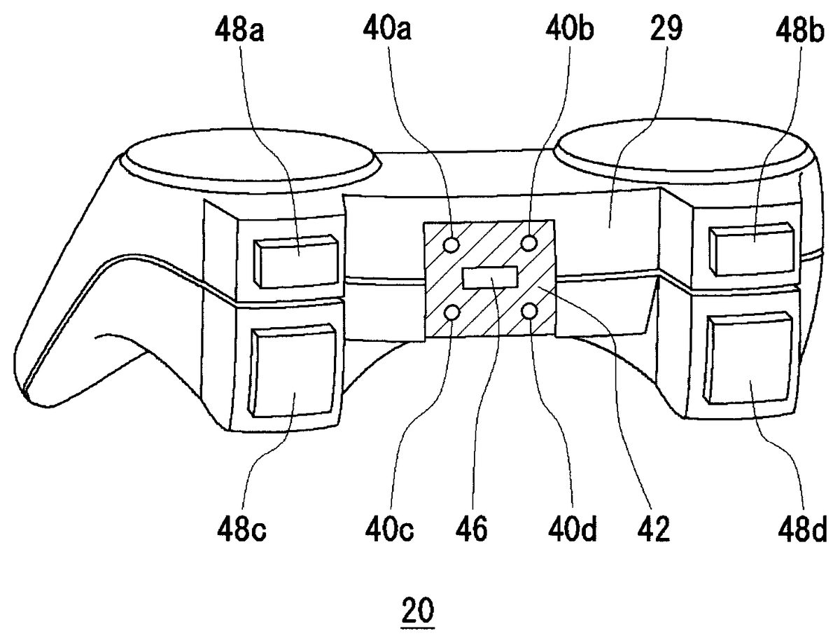
FIG. 3shows the external configuration of the controller from the rear. InFIG. 3, the arrow keys21, the operation buttons26, and the like provided on the case top30of the controller20are omitted. An LED layout area42is provided on the case rear29. A first LED40a, a second LED40b, a third LED40c, and a fourth LED40dare arranged in the LED layout area42. Hereinafter, the first LED40a, the second LED40b, the third LED40c, and the fourth LED40dwill be referred to collectively as “LEDs40.” The LED layout area42is provided in the central area of the case rear29. A USB connector46is provided at the center of the LED layout area42. A USB cable extending from the game apparatus10may be connected to the USB connector46to charge the controller20. It should be appreciated that the controller20can also be used as a cabled controller when the USB cable is connected.
Operation buttons48a,48b,48c, and48dare provided on the case rear29both to the right and to the left of the LED layout area42. The operation buttons48a,48b,48c, and48dare located at positions where they can be operated with the tips of the forefingers when the user holds the left grip28aand the right grip28b. This precludes the LEDs40from being covered by the forefingers while the operation buttons48a,48b,48c, and48dare operated.
The LEDs40are used as indicators for indicating the controller number. From the viewpoint of the user who uses the controller20, it is undesirable to arrange the LEDs40on the exposed case top30since they only have to be checked once. However, when there are other users, the LEDs40arranged on the case rear29have the advantage of being easily viewable by the other users. Furthermore, since the LED button31is positioned on the case top30, the LEDs40may be confusing if they are arranged there. For these reasons, the controller20is configured with the LEDs40on the case rear29.
The image pickup apparatus2acquires RGB luminance values pixel by pixel. In order for lighted LEDs40to be detected accurately, it is preferable that the LEDs40and the peripheral area around the LEDs40have a high lightness contrast. For this purpose, the LED layout area42has a darker color than the adjacent color of the case, such as black. The LED layout area42is made of a black semitransparent plate, and the LEDs40are arranged behind it, i.e., inside the case. Consequently, the LEDs40are invisible to the image pickup apparatus2when not lit, and an image of them can be captured only when lit. The black semitransparent plate can diffuse light so that the narrow directivity of the LEDs40is transformed into wide directivity. Arranging the LEDs40in the LED layout area42can therefore enhance the contrast of the lighted LEDs40. This makes it possible to extract the LED images from frame images effectively in subsequent image processing.
The first LED40a, the second LED40b, the third LED40c, and the fourth LED40dare arranged in a predetermined two-dimensional pattern. For example, the first LED40a, the second LED40b, the third LED40c, and the fourth LED40dare arranged in positions corresponding to the vertexes of a rectangle. The game apparatus10is provided with this positional relationship in advance, and uses it when extracting LED images. It should be appreciated that numerals are stamped or printed near the respective LEDs40, so that the user can check the numerals near lighted LEDs40to recognize the controller number.
FIG. 4shows the internal configuration of the controller. The controller20has a wireless communication module58, a processing unit60, the LEDs40, and a vibrator44. The wireless communication module58can transmit and receive data to/from a wireless communication module of the game apparatus10. The processing unit60performs various processing for the controller20.
The processing unit60includes a main control unit50, an input accepting unit52, a pulse width modulation (PWM) control unit54, and a drive unit56. The main control unit50exchanges necessary data with the wireless communication module58.
The input accepting unit52receives input information from the input units, including the arrow keys21, the operation buttons26, and the analog stick27, and sends the information to the main control unit50. The main control unit50supplies the received input information to the wireless communication module58. The wireless communication module58transmits it to the game apparatus10at the right time. Moreover, when receiving a vibration control signal from the game apparatus10, the wireless communication module58supplies it to the main control unit50. Based on the vibration control signal, the main control unit50operates the drive unit56which makes the vibrator44vibrate. The drive unit56may be configured as a switch for driving the vibrator44, or as a PWM control unit which adjusts the duty ratio of the supply voltage thereto.
In the present embodiment, the PWM control unit54is composed of a first PWM control unit54a, a second PWM control unit54b, a third PWM control unit54c, and a fourth PWM control unit54d. The first PWM control unit54a, the second PWM control unit54b, the third PWM control unit54c, and the fourth PWM control unit54dare provided in order to control the lighting of the first LED40a, the second LED40b, the third LED40c, and the fourth LED40d, respectively. The PWM control unit54controls the voltages to be applied to the LEDs40by pulse width modulation (PWM). For example, the PWM control unit54can PWM-control the applied voltages at high frequencies of several kilohertz, thereby adjusting the luminances of the LEDs40. The PWM control unit54can also PWM-control the applied voltages at low frequencies of several hertz to one hundred hertz or so, thereby allowing the image pickup apparatus2to recognize whether the LEDs40are lit or unlit.
In the game system1of the present embodiment, a user who wishes to join the game system1initially makes his/her controller20establish communication with the game apparatus10. At this time, identification information regarding the controller20, such as a Bluetooth address, is passed to the game apparatus10. Subsequent communication will be held based on this Bluetooth address. It should be appreciated that device addresses such as a MAC address may be used if Bluetooth is not used as the communication protocol. After the communication is established, the user can join the game application.
Here, information for specifying a controller number is transmitted from the game apparatus10to the controller20. Based on this number specification information, the main control unit50lights only an LED or LEDs40that correspond(s) to the given controller number. The user can thus recognize the controller number of his/her own controller20. It should be appreciated that a control signal for instructing to light LEDs40corresponding to the controller number may be transmitted from the game apparatus10, instead of the number specification information. As above, the main control unit50can light any of the LEDs40.
In the game system1of the present embodiment, the game apparatus10estimates the position and orientation of the controller20based on a frame image that is captured when all the LEDs40ato40dare lit. The estimated position and orientation are used as an input to the game application to be run. The game apparatus also accepts operation inputs from the arrow keys21, the operation buttons26, and the like of the controller20. Based on such input information, the game apparatus10generates game parameters of the game application, controls the progress of the game, and generates AV data for game images and game sounds. The AV data is output from the image display apparatus3and the sound output apparatus4. Watching the game screen, the user moves the controller20in real space, and also makes operation inputs on the arrow key21and the operation button26to play the game. A description will now be given of the processing in the game apparatus10.
FIG. 5shows the configuration of the game apparatus. The game apparatus10includes an input unit100, an image processing unit102, a position estimating unit104, a blink instruction unit106, a wireless communication module108, an application processing unit110, and an output unit112. The processing functions of the game apparatus10in the present embodiment are realized by such components as a CPU, a memory, and a program loaded into the memory. The diagram shows functional blocks that can be realized through the cooperation of these components. The program may be built into the game apparatus10, or may be supplied from an external recording medium. It will thus be understood by those skilled in the art that these functional blocks may be configured in various forms, including hardware alone, software alone, and combinations of these. In the shown example, the CPU of the game apparatus10has the functions of the image processing unit102, the position estimating unit104, the blink instruction unit106, and the application processing unit110. Depending on the hardware configuration, the game apparatus10may have a plurality of CPUs. In such cases, one of the CPUs may function as the application processing unit110which executes the game application. The other CPU(s) may serve as the image processing unit102which processes images captured by the image pickup apparatus2, the position estimating unit104, and the blink instruction unit106.
The wireless communication module108establishes wireless communication with the wireless communication module58of the controller20. In the phase of establishing synchronization, the wireless communication module108inquires for connection, i.e., performs “inquiry” processing regarding terminal devices including adjacent controllers20. Specifically, the wireless communication module108broadcasts an IQ (inquiry) packet to terminal devices nearby. The wireless communication modules58of controllers20that receive the IQ packet return an FHS (Frequency Hop Synchronization) packet, which includes a Bluetooth address and Bluetooth clock information, to the game apparatus10. At this time, a fixed hopping pattern dedicated to and defined for inquiry is used for transmission and reception because no consensus as to a frequency hopping pattern has yet been made between the game apparatus10and the controllers20.
The wireless communication module108receives the FHS packets from the controllers20, and recognizes the kinds of controllers20which are there. Then, it transmits an ID packet to a given controller20. This corresponds to “call processing” by the wireless communication module108. When a response to the ID packet is returned from the given controller20, the wireless communication module108transmits an FHS packet to the controller20, thereby notifying the controller20of its own address and clock. This makes it possible for the game apparatus10and the controller20to use the same hopping pattern.
When a “call” is made, the controller20and the game apparatus10form a piconet therebetween and enter a “connected” state. A piconet refers to a network that is formed temporarily between Bluetooth terminals when the terminals are put close to each other. Up to eight Bluetooth terminals can join a single piconet. The connecting controller20is given a slave identifier, or a 3-bit address (1 to 7) designated for a connected controller20, from the wireless communication module108. This slave identifier will be called AM_ADDR (Active Member ADDRess). In the “connected” state, control packets for setting a communication link are exchanged to enable “data transfer.”
When the controller20enters the connected state and joins the game application, the application processing unit110assigns a controller number to the controller20, and generates number specification information for specifying the controller number. The wireless communication module108transmits the number specification information to the controller20. Receiving the number specification information, the controller20lights the corresponding LED(s)40. It should be appreciated that the wireless communication module108may transmit a control signal that instructs LEDs40to be lit corresponding to the controller number, instead of the number instruction information.
When the game application is started, the blink instruction unit106generates a control signal for specifying a blink pattern so that the controller20blinks in predetermined cycles. This blink control signal is transmitted from the wireless communication module108to the controller20.
The input unit100is configured as a USB interface, and acquires frame images from the image pickup apparatus2at a capturing cycle (for example, 30 frames/second). The image processing unit102extracts LED images from frame images according to an LED extraction algorithm to be described later. The position estimating unit106acquires position information regarding the LED images from the extracted LED images, and estimates the position and orientation of the controller20. The position estimating unit104may function as a position acquisition unit since it acquires position information regarding the LED images. It should be appreciated that the position of the controller20may be defined as the barycentric point between the images of four LEDs.
The position information and/or the orientation information regarding the controller20, estimated from the positions and orientations of the four lit LEDs40, is used as an input to the game application. For that purpose, the position information and the orientation information regarding the controller20, estimated by the position estimating unit104, are sent to the application processing unit110in succession and reflected in the processing of the application. User inputs made by operating the arrow key21and the like of the controller20are also sent to the application processing unit110through the wireless communication module108. The application processing unit110advances the game based on the position and orientation information regarding the controller20and the operation inputs from the controller20, and generates image signals and sound signals that show the results of the processing of the game application. The image signals and the sound signals are sent from the output unit112to the image display apparatus3and the sound output apparatus4for output, respectively.
FIG. 6shows the configuration of the image processing unit. The image processing unit102includes a frame image acquisition unit130, a current frame buffer132, a previous frame buffer134, a differential image generating unit136, a binary image generating unit138, a logic operation unit140, and an LED image extracting unit142.
The frame image acquisition unit130acquires frame image data from the input unit100, and stores it temporarily in the current frame buffer132. The previous frame buffer134contains data regarding the last frame image. The differential image generating unit136generates a differential image between the current frame data stored in the current frame buffer132and the previous frame data stored in the previous frame buffer134. A differential image function F(x, y) is given by the following equation
F(x,y)=√{square root over ((Pr−Cr)2+(Pg−Cg)2+(Pb−Cb)2)}−Th(1)
where Pr is the R pixel value, Pg is the G pixel value, and Pb is the B pixel value of the previous frame data at coordinates (x, y) in that frame image, and Cr is the R pixel value, Cg is the G pixel value, and Cb is the B pixel value of the current frame data at the same coordinates (x, y).
Here, Th is a predetermined threshold. If F(x, y) is greater than 0, the pixel values at coordinates (x, y) are encoded to “1”. Then, the pixel will be displayed in white. On the other hand, if F(x, y) is less than or equal to 0, the pixel values at coordinates (x, y) are encoded to “0”. Then, the pixel will be displayed in black. It follows that the differential image generated by the differential image generating unit136is a binarized image. The differential image can be generated to eliminate the effect of objects that remain motionless between the previous frame image and the current frame image.
The binary image generating unit138binarizes the current frame data using a predetermined threshold, thereby generating a binary image. The binary image generating unit138encodes the pixel values of pixels that have luminances higher than the predetermined threshold into “1.” It encodes the pixel values of pixels that have luminances lower than or equal to the predetermined threshold into “0.” Generating a binary image of the current frame image can extract only the bright objects in the current frame image.
The logic operation unit140performs a logic operation between the differential image generated by the differential image generating unit136and the binary image generated by the binary image generating unit138, thereby generating a logic operation image. More specifically, the logic operation unit140performs an AND operation between the pixel values of the differential image and the pixel values of the binary image pixel by pixel, thereby generating an AND image. This AND image is generated by performing an AND operation between the corresponding pixels of the differential image and the binary image mathematically.
FIG. 7Ashows a current frame image. The current frame image shows a situation where a user holds the controller20for game play, and a lamp is lit on the right. Here, the LEDs40of the controller20are all lit. All the LEDs40emit light in an identical lighting pattern with an identical luminance.
FIG. 7Bshows a differential image between the current frame image and a previous frame image. When the controller20is moved from its position in the previous frame image, the differential image is generated from the equation (1). In this example, the controller20and at least some of the areas of the body that move with the controller20are acquired as a white image (with pixel values of “1”). Such a white image is not always acquired, however, and what is shown inFIG. 7Bis just an example of the differential image which might be generated when the equation (1) is satisfied. The lamp is not included in the differential image since it is motionless. It should be appreciated that the white image of the controller20will not be acquired if the user does not move the controller20.
FIG. 8Ashows a binary image of the current frame image. In the binary image, high-luminance areas ofFIG. 7A, i.e., the lighted LEDs and the illumination lamp are turned into white images. For the sake of reducing foreign noise, the threshold for the binarization processing is desirably set to a luminance value that is determined by subtracting a predetermined margin value from the luminance of the LED emission.
FIG. 8Bshows an AND image. The AND image is obtained by performing an AND operation between the differential image shown inFIG. 7Band the binary image shown inFIG. 8A. In the differential image and the binary image, the white pixels have pixel values of “1” and the black pixels have pixel values of “0”. Thus, only the pixels that are present as white pixels in both images appear as white pixels in the AND image.
As above, the differential image and the binary image can be logical AND operated to generate an AND image which is easier to extract LED images from. The AND image is sent to the LED image extracting unit142.
When the AND image has been generated, the previous frame data retained in the previous frame buffer134is overwritten with the current frame data retained in the current frame buffer132. This overwrite processing may be performed immediately after the previous frame buffer134is read by the differential image generating unit136. Subsequently, the current frame data retained in the current frame buffer132is overwritten with the next frame data, and the next frame is subjected to the process of generating an AND image.
The LED image extracting unit142extracts LED images from the AND image. To extract LED images, the LED image extracting unit142initially detects candidates for LED images. Then, the LED image extracting unit142assumes any one of the candidates to be the first LED40a, and searches the peripheral area for a candidate for an LED image that may be the second LED40b. If the second LED40bis found, the LED image extracting unit142searches the peripheral area of the first LED40aagain for a candidate for an LED image that may be the third LED40c. If the third LED40cis found, it searches the peripheral area for a candidate for an LED image that may be the fourth LED40d. Note that the LED image extracting unit142has been provided with the two-dimensional pattern to be formed by the plurality of LEDs40in advance, and uses this two-dimensional pattern to extract the LED images. For the sake of convenience, the following description will deal with the case where the first LED40a, the second LED40b, the third LED40c, and the LED40dform the vertexes of a square on the case rear29of the controller20.
It should be appreciated that the LED image extracting unit142can also extract LED images from the binary image without using the AND image. Binary images contain noise as well as LED images. It is possible, however, to detect the positions and orientations of LED images by using binary images if the LED images cannot be obtained from differential images. The procedure shown below can be performed by using either an AND image or a binary image. Since AND images contain less noise components other than the LED images, the use of the AND image improves the processing speed.
FIG. 9is a flowchart showing the procedure for detecting LED image candidates. The LED image extracting unit142acquires an area of the AND image where consecutive white pixels (pixels having pixel values of “1”) are found, as a single connected area (S100). Next, the LED image extracting unit142extracts the edges of the connected area of white pixels, and determines a minor side and a major side (S102).
The LED image extracting unit142determines whether or not the minor side contains pixels more than or equal to a predetermined number of pixels Ma (S104). If the minor side contains pixels less than the number of pixels Ma (N at S104), the LED image extracting unit142stops processing this connected area of white pixels since it is not an LED image. If the minor side contains pixels more than or equal to the number of pixels Ma (Y at S104), the LED image extracting unit142determines whether or not the major side contains pixels less than or equal to a predetermined number of pixels Mb (S106). If the major side contains pixels more than the number of pixels Mb (N at S106), the LED image extracting unit142stops processing this connected area of white pixels since it is not an LED image. If the major side contains pixels less than or equal to the number of pixels Mb (Y at S106), the LED image extracting unit142acquires the number of pixels that constitute the connected area of white pixels since it is a candidate for an LED image (S108). This LED image candidate detection processing is repeated on all the connected areas of white pixels. The LED image candidates included in the AND image can be detected in this way. Note that the coordinates of the LED image candidates are determined to be the barycenters of the respective connected areas.
FIG. 10is a flowchart showing the procedure for LED extraction processing. The LED image extracting unit142assumes any one of the detected LED image candidates to be the first LED40a(S120). Next, it determines whether or not there is any LED image candidate that satisfies the conditions for it to be the second LED40bwith respect to the first LED40a(S122). If there is any LED image candidate that may be the second LED40b(Y at S122), the LED image extracting unit142determines whether or not there is any LED image candidate that satisfies the conditions for it to be the third LED40cwith respect to the first LED40aand the second LED40b(S124). If there is any LED image candidate that may be the third LED40c(Y at S122), the LED image extracting unit142determines whether or not there is any LED image candidate that satisfies the conditions for it to be the fourth LED40dwith respect to the first LED40a, the second LED40b, and the third LED40c(S126). If there is any LED image candidate that may be the fourth LED40d(Y at S126), it follows that the first LED40ato the fourth LED40dof the controller20have been extracted. It should be appreciated that if there is no candidate for the second LED image (N at S122), if there is no candidate for the third LED image (N at S124), or if there is no candidate for the fourth LED image (N at S126), then another LED image candidate is assumed to be the first LED40aand the process ofFIG. 8is performed again.
For the sake of reducing the processing load, the LED extraction process may be performed on the assumption that the orientation of the controller20is not inclined beyond a predetermined angle. Since the LEDs40have a relatively high directivity, it is difficult for the image pickup apparatus2to receive their light when the controller20is inclined greatly. Utilizing this directivity of the LEDs40, it is possible to significantly reduce the processing load in searching for LED image candidates by performing the LED image extraction process with the assumption that the inclination from the first LED40awill not exceed a predetermined angle (for example, 45°).
Since the present embodiment uses the differential image between the previous frame image and the current frame image for the above process, the images of the LEDs40are excluded from the differential image when the controller20is motionless. The use of the differential image therefore does not ensure that LED images will always be found by the LED extraction processing shown inFIG. 10. If no LED image is found in the LED extraction processing shown inFIG. 10, the position estimating unit104acquires the position information and orientation information regarding the controller20in the previous frame, estimating that the controller20has remained stationary in the same position as in the previous frame. At this point, the position estimating unit104may extract LED images by using the binary image.
FIG. 11is a flowchart showing the procedure for the second LED detection process shown in S122ofFIG. 10. Suppose that the number of pixels constituting the LED image candidate that is assumed to be the first LED40ais N. Initially, the LED image extracting unit142determines whether or not an LED image candidate has pixels no less than ½×N and no more than 2N (S140). This is based on the fact that LED images will not be much different from that of the first LED40ain size or shape. If the number of pixels constituting the LED image candidate falls within the predetermined range around the number of pixels N (Y at S140), the LED image extracting unit142determines whether or not the LED image candidate lies on the right of the first LED40a(S142). Whether it is considered to be to the right or not is on the basis of whether or not the LED image candidate falls within the range of 45° top right and 45° bottom right of the first LED40a. If it is to the right of the first LED40a(Y at S142), the LED image extracting unit142determines whether or not the distance D12between the first LED40aand the LED image candidate is no less than Da and no greater than Db (S144). This determination is made on the basis that the candidate cannot be the second LED40bif the two are spaced too close or too far from each other. If the distance D12is no less than Da and no greater than Db (Y at S144), it is determined that the LED image candidate may be the second LED40b. This confirms the presence of the second LED40b(S146). On the other hand, if the number of pixels constituting the LED image candidate does not fall within the predetermined range (N at S140), if the candidate is not to the right of the LED40a(N at S142), or if the distance D12does not fall within the predetermined range (N at S144), then it is determined that the LED image candidate is not the second LED40b.
FIG. 12is a flowchart showing the procedure for the third LED detection process shown in S124ofFIG. 10. Suppose that the number of pixels constituting the LED image candidate that is assumed to be the first LED40ais N. Initially, the LED image extracting unit142determines whether or not an LED image candidate has pixels no less than ½×N and no more than 2N (S160). If the number of pixels constituting the LED image candidate falls within the predetermined range around the number of pixels N (Y at S160), the LED image extracting unit142determines whether or not the LED image candidate lies below the first LED40a(S162). Whether it is considered to be below or not is determined on the basis of whether or not the LED image candidate falls within the range of 45° bottom left and 45° bottom right of the first LED40a. If it is below the LED40a(Y at S162), the LED image extracting unit142determines whether or not the distance between the first LED40aand the LED image candidate is no less than 1/√2×D12and no greater than √2×D12(S164). This determination is made on the basis that the candidate cannot be the third LED40cif the two are spaced too close or too far from each other. If the distance is no less than 1/√2×D12and no greater than √2×D12(Y at S164), the LED image extracting unit142determines whether or not the angle formed between the segment from the first LED40ato the second LED40band the segment from the first LED40ato the LED image candidate falls within a predetermined range (S166). At this point, if the angle falls within the predetermined range (Y at S166), it is determined that the LED image candidate may be the third LED40c. This confirms the presence of the third LED40c(S168). On the other hand, if the number of pixels constituting the LED image candidate does not fall within the predetermined range (N at S160), if the candidate is not below the LED40a(N at S162), if the distance from the first LED40adoes not fall within the predetermined range (N at S164), or if the angle does not fall within the predetermined range (N at S166), then it is determined that the LED image candidate is not the third LED40c(S170).
FIG. 13is a flowchart showing the procedure for the fourth LED detection process shown in S126ofFIG. 10. Suppose that the number of pixels constituting the LED image candidate that is assumed to be the first LED40ais N. Initially, the LED image extracting unit142determines whether or not an LED image candidate has pixels no less than ½×N and no more than 2N (S180). If the number of pixels constituting the LED image candidate falls within the predetermined range around the number of pixels N (Y at S180), the LED image extracting unit142determines whether or not the angle formed between a vector extending from the first LED40ato the second LED40band a vector extending from the third LED40cto the LED image candidate is no greater than a predetermined value (S182). If the angle formed between the vector extending from the first LED40ato the second LED40band the vector extending from the third LED40cto the LED image candidate is smaller than or equal to the predetermined value (Y at S182), then the LED image extracting unit142determines whether or not the angle formed between a vector extending from the first LED40ato the third LED40cand a vector extending from the second LED40bto the LED image candidate is no smaller than a predetermined value (S184). If the angle formed between the vector extending from the first LED40ato the third LED40cand the vector extending from the second LED40bto the LED image candidate is smaller than or equal to the predetermined value (Y at S184), it is determined that the LED image candidate may be the fourth LED40d. This confirms the presence of the fourth LED40d(S186). On the other hand, if the number of pixels constituting the LED image candidate does not fall within the predetermined range (N at S180), if the angle formed between the vector extending from the first LED40ato the second LED40band the vector extending from the third LED40cto the LED image candidate exceeds the predetermined value (N at S182), or if the angle formed between the vector extending from the first LED40ato the third LED40cand the vector extending from the second LED40bto the LED image candidate exceeds the predetermined value (N at S184), then the LED image candidate is determined not to be the fourth LED40d(S188).
Through the foregoing process, the LED image extracting unit142can extract the images of the first LED40ato the fourth LED40dfrom the AND image. Position information regarding the extracted images of the first LED40ato the fourth LED40dis sent to the position estimating unit104.
The position estimating unit104acquires position information regarding the images of the first LED40ato the fourth LED40din the frame image based on the two-dimensional arrangement of the LEDs40on the controller20. The position estimating unit104determines an affine transformation between the first LED40a, the second LED40b, the third LED40c, and the fourth LED40d, and thereby calculates the position and orientation of the controller20in real space. The position of the controller20in real space is expressed by coordinates (X, Y, Z) on an orthogonal coordinate system. The orientation in real space is expressed by the angles of rotation around the X-axis, the Y-axis, and the Z-axis. Determining the coordinates and the angles of rotation as to the three axes, the position estimating unit104can estimate the position within the space, including the distance from the image pickup apparatus2. The position estimating unit104may also determine an affine transformation to estimate the position of the controller20within a frame image. For example, the XY coordinates in XYZ space can be used to obtain the position within the frame image. The position estimating unit104sends the estimated position and orientation of the controller20to the application processing unit110.
To avoid misidentification of the LEDs40, the position estimating unit104processes the currently acquired positions of the LED images as an error if the amount of change between the previously acquired positions of the LED images and the currently acquired positions of the LED images exceeds a predetermined value. That is, when the positions or orientations vary more than a predetermined value during a single frame, it might be the case that other objects are possibly misidentified as the LEDs40due to foreign factors. The extracted position information regarding the LEDs40is discarded for this reason.
Even in those cases, however, the controller20might actually be moved by that large amount of change. Therefore, the position estimating unit104may count the number of errors occurring in succession, and process the acquired positions of the LED images as normal ones when the count reaches a predetermined value.
The position estimating unit104can also estimate the directions of movement and the speeds of movement of the LEDs40, for example, based on the current frame image or the AND image. For example, when the shutter speed of the image pickup apparatus2is reduced, the LEDs40may be captured as elliptic or rectangular images. Accordingly, the directions of movement as well as the moving speeds can be estimated from the shapes of the LED images. For example, if the directions and the speeds of movement can be estimated, it is possible to estimate the position and orientation of the controller20even if the controller20abruptly disappears from the view of the image pickup apparatus2. When the shapes of all the LEDs40are leaning in the same direction, the direction and the speed of movement of the controller20may be estimated.
The application processing unit110reflects the estimated position and orientation of the controller20as a game input in the processing of the game application. This reflection may be effected in various ways. In a most intuitive fashion, a virtual object following the estimated position of the controller20may be displayed at the corresponding position in the game image. When the user moves the controller20with respect to the image pickup apparatus2, the virtual object can be moved to follow the motion in the game image.
It should be appreciated that the positions and orientations of the LEDs40are ideally determined in each frame image and accordingly reflected on the game images in succession. Nevertheless, it may sometimes be impossible to determine the positions and orientations of the LEDs40in frame images, depending on environmental conditions including the orientation of the controller20and the ambient light. When such a condition lasts for a period of time and then the positions and orientations of the LEDs40are suddenly reacquired, it follows that the virtual object at rest suddenly jumps to the new position, which is disconcerting for the user. Therefore, even if the positions and orientations of the LEDs40can be detected from the AND image again, the virtual object will not be moved to the acquired position on the game image. Instead, follow-up processing will be performed so that the virtual object can move smoothly even when there is some information loss.
FIGS. 14A and 14Bare diagrams for explaining an algorithm by which the virtual object corresponding to the controller makes a smooth follow-up operation within the game screen. For the sake of convenience, the following description will deal with the case where the virtual object changes in position. The same algorithm can also be applied to a change of orientation.
Suppose that the position estimating unit104determines affine transformations, and position parameters Pi−1, Pi, and Pi+1are derived (the suffix of P indicates the number of the frame of the game screen). Initially, a description will be given of the case where the frame image switches and the position parameter changes from Pito Pi+1.
When the new position parameter (Pi+1) is obtained, a position parameter to be reflected on the game screen is given by the following equation:
Qi+1=(Qi+Pi+1)/2.
That is, instead of shifting to the new position parameter Pi−1directly, a new position parameter on the game screen is set to the midpoint between the position parameter of the previous frame on the game screen and the new position parameter Pi−1of the current frame. It should be appreciated that the position parameter Qi+1need not necessarily be the midpoint between the position parameter Qiand the position parameter Pi−1, but may be a different point that sections the segment between the position parameter Qiand the position parameter Pi−1at A:B.
FIG. 12Bshows an example where the position parameter Pi−1cannot be acquired. This algorithm is effective in such cases. Here, the last position parameter is used instead of Pi−1:
Qi+1=(Qi+Pi)/2,
where Piis the last position parameter.
When position parameters Q on the game screen are acquired by this algorithm, it is possible to move the virtual object in continuous steps even when the controller20makes large movements in space or when it cannot be extracted from AND images. This can avoid situations such as the virtual object suddenly freezing or suddenly moving in the game image, and can achieve smooth follow-up processing for the controller20.
Up to this point, the present invention has been described in conjunction with the embodiment thereof. This embodiment is given solely by way of illustration. It will be understood by those skilled in the art that various modifications may be made to combinations of the foregoing components and processes, and all such modifications are also intended to fall within the scope of the present invention.
In the embodiment, the image pickup apparatus2captures an image of the controller20, and the position and orientation of the controller20are estimated from the frame images. The position information and the orientation information are then reflected in the processing of the game application. The LEDs40of the controller20may be lit in different lighting patterns, for example, depending of the progress of the game application.
Immediately after the user joins the game application, the game apparatus10may transmit a control signal to the controller20so that the four LEDs40are blinked at a predetermined low frequency. The blink instruction unit106generates a control signal for instructing a blink pattern of a predetermined frequency to the controller20. This low-frequency blink control signal is transmitted from the wireless communication module108to the controller20. It should be appreciated that if there are a plurality of controllers20, the controllers20are given respective different blink frequencies.
The controller20blinks the LEDs40at the instructed low frequency, and the image pickup apparatus2captures frame images at capturing cycles of 30 frames/second. From the plurality of frame images, the game apparatus10extracts the images of LEDs that are lit on/off at the predetermined cycles. If the game system1includes a plurality of controllers20, the controllers20are given respective different lighting cycles. This makes it possible to check the positions of the controllers20, and identify each individual controller20separately. This process ideally needs only be performed once after the game application has been joined. In real space, however, controllers20may suddenly disappear from the view of the image pickup apparatus2. For that reason, the controllers20may blink the LEDs40at low frequencies set for the respective controllers at predetermined intervals such as every few seconds.
For example, when the four LEDs40are blinked at a low frequency, frames in which the LEDs40can be captured and frames in which they cannot will occur alternately. If the LEDs40are controlled to light on/off at 45 Hz with respect to a capturing cycle of 30 frames/seconds, then the LEDs40are alternately captured in two consecutive frames and not in the next two. Since the LEDs40are captured in some frame images and not in others, it is possible to acquire position information even if the LEDs40are motionless.
Here, the low-frequency lighting refers to the mode of lighting at such frequencies that the lighted LEDs are captured in some frames and not in others, with respect to the capturing cycles. High-frequency lighting, on the other hand, refers to the mode of lighting at such frequencies that the lighted LEDs are always captured in frame images, with reference to the capturing cycles (30 frames/second) of the image pickup apparatus2. For example, even when the LEDs40are blinked at 1 kHz, the lighted LEDs can be captured in some frames and not in others if the capturing cycle of the image pickup apparatus2is extremely short. This makes it possible to acquire position information even if the LEDs40are motionless.
The positions and orientations of the LEDs40that are blinked at high frequencies are used as an input to the game application. Then, the position information regarding the controller20, estimated by the position estimating unit104, is sent to the application processing unit110in succession and reflected in the processing of the application. User's operation inputs on the arrow key21and the like of the controller20are also sent to the application processing unit110through the wireless communication module108. The application processing unit110progresses the game based on the position and orientation information regarding the controller20and the operation inputs from the controller20, and generates image signals and sound signals that show the results of the processing of the game application.
In a modification, one of the four LEDs40can be lit with a blink pattern different from that of the other LEDs40so that the particular LED40can be identified. For example, when three LEDs are blinked at a high frequency and one LED is blinked at a low frequency, it is possible, for example, to check which is the first LED40ain the frame image.
By detecting the position and orientation of the controller20in real space and reflecting them in the processing of a game application, it is possible to realize new types of game applications. Take a tennis game, for example. The controller20can be moved to progress the game, provided that the height of the controller20in a frame image represents the height of the point where a tennis ball is hit, the direction of the controller20the direction of the hit ball, and the moving speed of the controller20the power to hit the ball. Since these motions are similar to those of swinging a real racket, it is possible to give the user a sensory experience similar to actually playing tennis. In this case, since the buttons and keys of the controller20can also be used as game inputs, it is possible to provide sensuously innovative ways for a user to make game inputs while maintaining conventional game operation inputs. In this way, the LEDs provided as indicators on the controller20can be fully utilized to further enhance the variety of game applications available.
For example, the power to hit a ball may be determined by button operations on the controller20. The conventional type of button operations and the innovative ways of game inputs can be combined to achieve new gameability. For example, it is possible to create a tennis game such that a ball can be tossed up by making a button input while designating the target position for the ball to hit the ground on the opponent side of the court, and a strong service can be made by moving the controller20.
Another example of the game application is a motorcycle racing game. The orientation of the controller20may be manipulated and utilized as game inputs for controlling a motorcycle. Here, the speed may be determined by the moving speed of the controller20, or may be determined by button inputs. As above, the conventional type of button inputs, static inputs made by the position and orientation of the controller20, and dynamic inputs based on changes of state, such as the moving speed of the controller20, can be used in combination to improve the operability of game applications.
For example, when the controller20is about to go out of the capturing range of the image pickup apparatus2, the application processing unit110may notify the user of the possibility of going out based on the position information on the controller20. Moreover, when the controller20is about to go out of range, the application processing unit110may generate a vibration control signal for making the controller20vibrate its vibrator, and transmit it from the wireless communication module108. Furthermore, when a virtual object that follows the movement of the controller20is displayed on the game image, the application processing unit110may notify the user of the possibility of going out of range by moving the virtual object in a manner noticeable to the user. Whether the controller is about to go out or not may be determined, for example, based on position in frame images. The notification processing may be performed when the position of the controller20is estimated to be close to the edges of the frame image.
The features of the invention disclosed in the embodiment may be defined by the following items:
(Item 1)
An image processing apparatus which acquires a position of an illuminator image from a frame image input thereto, comprising:
a differential image generating unit which generates a differential image between a previous frame image and a current frame image;
a binary image generating unit which binarizes the current frame image with a threshold, thereby generating a binary image;
a logic operation unit which logically operates on the differential image and the binary image to generate a logic operation image;
an extraction unit which extracts an illuminator image from the logic operation image; and
a position acquisition unit which acquires the position of the illuminator image in the frame image.
(Item 2)
The image processing apparatus according to item 1, wherein the logic operation unit generates the logic operation image by performing an AND operation between pixel values of the differential image and pixel values of the binary image pixel by pixel.
(Item 3)
The image processing apparatus according to item 1 or 2, wherein the extraction unit recognizes a two-dimensional pattern to be formed by a plurality of illuminators in advance, and uses the two-dimensional pattern to extract the illuminator image.
(Item 4)
The image processing apparatus according to any one of items 1 to 3, wherein the position acquisition unit processes the position of an illuminator image acquired currently as an error if the amount of change between the position of an illuminator image acquired previously and the position of the illuminator image acquired currently exceeds a predetermined value.
(Item 5)
The image processing apparatus according to item 4, wherein the position acquisition unit counts the number of errors occurring in succession, and processes the position of an acquired illuminator image as normal or correct one if the count reaches a predetermined value.
Claims
- A controller for providing user operation commands to an apparatus, the controller comprising: a communication module configured to transmit the user operation commands to the apparatus;a plurality of light-emitting elements provided on a case of the controller;and a processing unit configured to cause the light-emitting elements to emit light, wherein the light-emitting elements are arranged in a pattern on the case such that the emitted light is captured in an image by an imaging device of the apparatus, wherein a position of the controller is determined based on a positional relationship of the light-emitting elements on the case affecting the emitted light captured in the image, wherein the position of the controller is detected based on at least an angle between respective areas of the emitted light in the image captured from the plurality of light-emitting elements, and wherein a first area of emitted light in the image is detected as a first of the plurality of light-emitting elements;a second area of emitted light in the image is detected as a second of the plurality of light-emitting elements;a third area of emitted light in the image is detected as a third of the plurality of light-emitting elements;and a fourth area of emitted light in the image is detected as a fourth of the plurality of light-emitting elements, at least when a first angle formed between a first vector, extending between the first area and the second area, and a second vector, extending between the third area and the fourth area, is no greater than a predetermined high threshold value.
- The controller of claim 1 , wherein the position of the controller is detected based on at least one distance between respective areas of the emitted light in the image captured from the plurality of light-emitting elements.
- The controller of claim 2 , wherein: a first area of emitted light in the image is detected as a first of the plurality of light-emitting elements;a second area of emitted light in the image is detected as a second of the plurality of light-emitting elements at least when a distance, D( 1 , 2 ), between the first area and the second area is between a predetermined lower limit and a predetermined higher limit, which are based on a positional relationship of the light-emitting elements on the case.
- The controller of claim 3 , wherein a third area of emitted light in the image is detected as a third of the plurality of light-emitting elements at least when a distance, D( 1 , 3 ), between the first area and the third area is between 1/√2×D( 1 , 2 ) and √2×D( 1 , 2 ).
- The controller of claim 1 , wherein the fourth area of emitted light in the image is detected as the fourth of the plurality of light-emitting elements, at least when: the first angle is no greater than the predetermined high threshold value;and a second angle formed between a third vector, extending between the first area and the third area, and a fourth vector, extending between the second area and the fourth area, is no smaller than a predetermined low threshold value.
- The controller of claim 1 , wherein: a first area of emitted light in the image is detected as a first of the plurality of light-emitting elements;and a further area of emitted light in the image is detected as a further one of the plurality of light-emitting elements at least when a number of pixels within the further area is between 1/2 ×N and 2×N, where N is a number of pixels contained in the first area.
- The controller of claim 1 , wherein the controller is a game controller and the apparatus is a game console apparatus.
- A method for providing user operation commands from a controller to an apparatus, the method comprising: providing a plurality of light-emitting elements on a case of the controller, where the light-emitting elements are arranged in a pattern on the case;causing the light-emitting elements to emit light;capturing the emitted light in an image by an imaging device of the apparatus;and determining a position of the controller based on a positional relationship of the light-emitting elements on the case affecting the emitted light captured in the image, wherein the position of the controller is detected based on at least an angle between respective areas of the emitted light in the image captured from the plurality of light-emitting elements, and wherein a first area of emitted light in the image is detected as a first of the plurality of light-emitting elements;a second area of emitted light in the image is detected as a second of the plurality of light-emitting elements;a third area of emitted light in the image is detected as a third of the plurality of light-emitting elements;and a fourth area of emitted light in the image is detected as a fourth of the plurality of light-emitting elements, at least when a first angle formed between a first vector, extending between the first area and the second area, and a second vector, extending between the third area and the fourth area, is no greater than a predetermined high threshold value.
- The method of claim 8 , wherein the position of the controller is detected based on at least one distance between respective areas of the emitted light in the image captured from the plurality of light-emitting elements.
- The method of claim 9 , wherein: a first area of emitted light in the image is detected as a first of the plurality of light-emitting elements;a second area of emitted light in the image is detected as a second of the plurality of light-emitting elements at least when a distance, D( 1 , 2 ), between the first area and the second area is between a predetermined lower limit and a predetermined higher limit, which are based on a positional relationship of the light-emitting elements on the case.
- The method of claim 10 , wherein a third area of emitted light in the image is detected as a third of the plurality of light-emitting elements at least when a distance, D( 1 , 3 ), between the first area and the third area is between 1/√×D( 1 , 2 ) and √2×D( 1 , 2 ).
- The method of claim 8 , wherein the fourth area of emitted light in the image is detected as the fourth of the plurality of light-emitting elements, at least when: the first angle is no greater than the predetermined high threshold value;and a second angle formed between a third vector, extending between the first area and the third area, and a fourth vector, extending between the second area and the fourth area, is no smaller than a predetermined low threshold value.
- The method of claim 8 , wherein: a first area of emitted light in the image is detected as a first of the plurality of light-emitting elements;and a further area of emitted light in the image is detected as a further one of the plurality of light-emitting elements at least when a number of pixels within the further area is between 1/2 ×N and 2×N, where N is a number of pixels contained in the first area.
- A system, comprising: an apparatus configured to process user operation commands;an imaging device configured to provide the apparatus with an image;and a controller for receiving the user operation commands from the user, the controller comprising: a communication module configured to transmit the user operation commands to the apparatus;a plurality of light-emitting elements provided on a case of the controller;and a processing unit configured to cause the light-emitting elements to emit light, wherein the light-emitting elements are arranged in a pattern on the case such that the emitted light is captured in an image by an imaging device of the apparatus, wherein a position of the controller is determined by the apparatus based on a positional relationship of the light-emitting elements on the case affecting the emitted light captured in the image, wherein the position of the controller is detected based on at least an angle between respective areas of the emitted light in the image captured from the plurality of light-emitting elements, and wherein a first area of emitted light in the image is detected as a first of the plurality of light-emitting elements;a second area of emitted light in the image is detected as a second of the plurality of light-emitting elements;a third area of emitted light in the image is detected as a third of the plurality of light-emitting elements;and a fourth area of emitted light in the image is detected as a fourth of the plurality of light-emitting elements, at least when a first angle formed between a first vector, extending between the first area and the second area, and a second vector, extending between the third area and the fourth area, is no greater than a predetermined high threshold value.
- The system of claim 14 , wherein the controller is a game controller and the apparatus is a game console apparatus.
Disclaimer: Data collected from the USPTO and may be malformed, incomplete, and/or otherwise inaccurate.