U.S. Pat. No. 9,561,441
STORAGE MEDIUM STORING VIDEO GAME PROGRAM FOR CALCULATING A DISTANCE BETWEEN A GAME CONTROLLER AND A REFERENCE
AssigneeNintendo Co., Ltd.
Issue DateMay 8, 2006
Illustrative Figure
Abstract
A game process is performed by obtaining control data from a game controller. Distance data associated with the distance between the game controller and a predetermined measured reference provided in a real space is calculated by using the control data obtained from the game controller. Then, a predetermined game process is performed on a virtual game world through an operation based on the value of the distance data. Then, the virtual game world after the game process is displayed on a display device.
Description
DESCRIPTION OF THE PREFERRED EMBODIMENTS First Embodiment Referring toFIG. 1, a video game system1according to a first embodiment of the present invention will now be described.FIG. 1shows an external view of the video game system1. In the present embodiment, the video game system1includes a home-console type video game device. Referring toFIG. 1, the video game system1includes a home-console type video game device (hereinafter simply “video game device”)3and a controller7for giving control information to the video game device3. The video game device3is connected, via a connection cord, to a display (hereinafter “monitor”)2provided with a speaker2a, such as a home television receiver. A receiver unit6is connected to the video game device3via a connection terminal. The receiver unit6receives transmit data wirelessly transmitted from the controller7, and the controller7and the video game device3are connected via wireless communications. The video game device3uses an optical disk4, being an example of an information storage medium, that can be received by the video game device3. Provided on the upper principal plane of the video game device3are an ON/OFF switch for turning ON/OFF the power of the video game device3, a reset switch for resetting a game process, and an OPEN switch for opening the upper lid of the video game device3. The lid opens up when the OPEN switch is pressed by the player so that the optical disk4can be put in place. The video game device3can also receive an external memory card5including a backup memory, or the like, for statically storing save data, or the like. The video game device3executes a video game program, or the like, stored in the optical disk4to obtain a game image, and displays the obtained game image on the monitor2. The video game device3may reproduce a past game status from save data stored in the external memory card5to obtain a game image ...
DESCRIPTION OF THE PREFERRED EMBODIMENTS
First Embodiment
Referring toFIG. 1, a video game system1according to a first embodiment of the present invention will now be described.FIG. 1shows an external view of the video game system1. In the present embodiment, the video game system1includes a home-console type video game device.
Referring toFIG. 1, the video game system1includes a home-console type video game device (hereinafter simply “video game device”)3and a controller7for giving control information to the video game device3. The video game device3is connected, via a connection cord, to a display (hereinafter “monitor”)2provided with a speaker2a, such as a home television receiver. A receiver unit6is connected to the video game device3via a connection terminal. The receiver unit6receives transmit data wirelessly transmitted from the controller7, and the controller7and the video game device3are connected via wireless communications. The video game device3uses an optical disk4, being an example of an information storage medium, that can be received by the video game device3. Provided on the upper principal plane of the video game device3are an ON/OFF switch for turning ON/OFF the power of the video game device3, a reset switch for resetting a game process, and an OPEN switch for opening the upper lid of the video game device3. The lid opens up when the OPEN switch is pressed by the player so that the optical disk4can be put in place.
The video game device3can also receive an external memory card5including a backup memory, or the like, for statically storing save data, or the like. The video game device3executes a video game program, or the like, stored in the optical disk4to obtain a game image, and displays the obtained game image on the monitor2. The video game device3may reproduce a past game status from save data stored in the external memory card5to obtain a game image for that past game status, and display the obtained game image on the monitor2. Then, the player of the video game device3can enjoy the game process by operating the controller7while watching the game image displayed on the monitor2.
The controller7wirelessly transmits, from a communications section75(to be described later) therein, transmit data to the video game device3, to which the receiver unit6is connected, by means of a technique such as Bluetooth (registered trademark), for example. The controller7is means for controlling a player object in a game space displayed on the monitor2. The controller7has a control section, including a plurality of control buttons, keys, sticks, etc. As will be more apparent from the following description, the controller7includes an image capturing/processing section74for capturing an image as viewed from the controller7. As an example of imaging targets to be captured by the image capturing/processing section74, two LED modules (hereinafter “markers”)8L and8R are provided around the display screen of the monitor2. The markers8L and8R output infrared light to the front side of the monitor2.
Referring now toFIG. 2, a configuration of the video game device3will be described.FIG. 2is a functional block diagram showing the video game device3.
Referring toFIG. 2, the video game device3includes a RISC CPU (Central Processing Unit)30, for example, for executing various programs. The CPU30executes a boot program stored in a boot ROM (not shown), thus initializing memory devices, such as a main memory33, and then executes a video game program stored in the optical disk4to perform a game process, etc., according to the video game program. Connected to the CPU30via a memory controller31are a GPU (Graphics Processing Unit)32, the main memory33, a DSP (Digital Signal Processor)34, and an ARAM (Audio RAM)35. The memory controller31is connected, via a predetermined bus, to a controller I/F (interface)36, a video I/F37, an external memory I/F38, an audio I/F39and a disk I/F41, which are connected to the receiver unit6, the monitor2, the external memory card5, the speaker2aand a disk drive40, respectively.
The GPU32is responsible for image processing based on instructions from the CPU30, and is a semiconductor chip, for example, capable of computations necessary for 3D graphics display. The GPU32performs the image process by using a memory dedicated for image processing (not shown) or a part of the memory area of the main memory33. The GPU32produces game image data or movie data to be displayed on the monitor2using these memory areas, and outputs the produced data to the monitor2via the memory controller31and the video I/F37as necessary.
The main memory33is a memory area used by the CPU30, and stores a video game program, etc., as necessary for processes performed by the CPU30. For example, the main memory33stores the video game program loaded from the optical disk4by the CPU30and various data, etc. The video game program, the various data, etc., stored in the main memory33are executed or processed by the CPU30.
The DSP34is for processing sound data, etc., produced by the CPU30when executing the video game program, and is connected to the ARAM35for storing the sound data, etc. The ARAM35is used when the DSP34performs a predetermined process (e.g., storing a video game program, sound data, etc., which have been loaded in advance). The DSP34reads out the sound data stored in the ARAM35, and outputs the sound data through the speaker2aprovided in the monitor2via the memory controller31and the audio I/F39.
The memory controller31is responsible for the overall control of data transfers, and is connected to the various I/F's described above. The controller I/F36includes, for example, four controller I/F portions36ato36d, each having a connector into which an external unit can be fitted for communicable connection between the external unit and the video game device3. For example, the receiver unit6may be fitted into the connector to be connected to the video game device3via the controller I/F36. As described above, the receiver unit6receives transmit data from the controller7, and outputs the transmit data to the CPU30via the controller I/F36. The monitor2is connected to the video I/F37. The external memory card5is connected to the external memory I/F38, whereby a backup memory, etc., provided in the external memory card5can be accessed. The audio I/F39is connected to the speaker2aprovided in the monitor2so that the sound data read out from the ARAM35by the DSP34or the sound data outputted directly from the disk drive40can be outputted through the speaker2a. The disk I/F41is connected to the disk drive40. The disk drive40reads out data from the optical disk4placed in a predetermined read-out position, and outputs the data to the bus or the audio I/F39of the video game device3.
Referring now toFIGS. 3 and 4, the controller7will be described.FIG. 3is a perspective view showing the controller7as viewed from the upper rear side.FIG. 4is a perspective view showing the controller7as viewed from the lower rear side.
The controller7shown inFIGS. 3 and 4includes a housing71formed by molding a plastic material, for example, and a plurality of control sections72are provided on the housing71. The housing71has a generally rectangular parallelepiped shape, with the longitudinal direction being the front-rear direction, and has an overall size such that it can be held in a hand of an adult or a child.
A cross-shaped key72ais provided on the upper surface of the housing71, centered in the left/right direction and near the front end. The cross-shaped key72ais a cross-shaped four-way push switch, in which four control portions associated with four different directions (forward, backward, left and right) indicated by arrows are provided in the protruding portions of the cross shape while being spaced apart from one another by 90°. The player can select one of the forward, backward, left and right directions by pressing down a corresponding one of the control portions of the cross-shaped key72a. For example, the player can control the cross-shaped key72ato move a player character, etc., in a virtual game world, or move a cursor, in a certain direction.
While the cross-shaped key72ais a control section that outputs a control signal according to a direction input operation by the player, it may be any other suitable type of a control section. For example, the cross-shaped key72amay be replaced by a combination switch including a ring-shaped four-way push switch and a center switch surrounded by the ring-shaped push switch. Alternatively, the cross-shaped key72amay be replaced by a stick-shaped control section protruding from the upper surface of the housing71, which outputs a control signal according to the direction in which it is tilted. Alternatively, the cross-shaped key72amay be replaced by a horizontally-movable (slidable) disc-shaped control section, which outputs a control signal according to the direction in which it is slid. Alternatively, the cross-shaped key72amay be replaced by a touch pad. Alternatively, the cross-shaped key72amay be replaced by a control section including at least four switches associated with different directions (forward, backward, left and right), which outputs a control signal according to the switch pressed by the player.
A plurality of control buttons72bto72gare provided on the upper surface of the housing71, closer to the rear end with respect to the cross-shaped key72a. The control buttons72bto72gare control sections, each of which outputs a control signal associated therewith when being pressed by the player. For example, the control buttons72bto72dmay be assigned a function as an X button, a Y button and a B button, respectively. For example, the control buttons72eto72gmay be assigned a function as a select switch, a menu switch and a start switch, respectively. Each of the control buttons72bto72gis assigned a function as specified in the video game program executed by the video game device3, the details of which will not be discussed herein as being not directly related to the description of the present invention. In the arrangement shown inFIG. 3, the control buttons72bto72dare arranged in the forward/backward direction while being centered in the left/right direction on the upper surface of the housing71. The control buttons72eto72gare arranged in the left/right direction between the control buttons72band72don the upper surface of the housing71. The control button72fis buried under the upper surface of the housing71so as to prevent the player from pressing the button unintentionally.
A control button72his provided on the upper surface of the housing71, closer to the front end with respect to the cross-shaped key72a. The control button72his a power switch for remotely turning ON/OFF the power of the video game device3from a remote position. The control button72his also buried under the upper surface of the housing71so as to prevent the player from pressing the button unintentionally.
A plurality of LEDs702are provided on the upper surface of the housing71, closer to the rear end with respect to the control button72c. The controller7is given a controller ID (number) for identifying the controller7from others. The LEDs702may, for example, be used for notifying the player of the controller ID being currently assigned to the controller7. Specifically, when transmit data is transmitted from the controller7to the receiver unit6, one or more of the LEDs34are lit depending on the controller ID.
A depressed portion is formed on the lower surface of the housing71. As will later be more apparent, the depressed portion of the lower surface of the housing71is located where the index or middle finger of the player lies when the player holds the controller7. A control button72iis provided on a slope on the rear side of the depressed portion. For example, the control button72iis a control section that functions as an A button, and used as a trigger switch in a shooter video game or for directing the attention of a player object toward a predetermined object.
An image sensing device743, forming a part of the image capturing/processing section74, is formed on the front side of the housing71. The image capturing/processing section74is a system for analyzing image data obtained by the controller7to determine each spot with high luminance and then to detect the centroid and the size thereof, and has a maximum sampling frequency of about 200 frames per second, for example, and is thus capable of following fast movements of the controller7. The details of the configuration of the image capturing/processing section74will be described later. A connector73is provided on the rear side of the housing71. The connector73is, for example, a 32-pin edge connector, and is used for connection between the controller7and a connection cable, which can be fitted into the connector.
Referring now toFIGS. 5A and 5B, an internal configuration of the controller7will be described.FIG. 5Ais a perspective view showing the controller7with an upper casing (a part of the housing71) taken off.FIG. 5Bis a perspective view showing the controller7with a lower casing (a part of the housing71) taken off.FIG. 5Ashows one side of a substrate700, andFIG. 5Bshows the other side thereof.
InFIG. 5A, the substrate700is secured in the housing71, and the control buttons72ato72h, an acceleration sensor701, the LEDs702, a quartz oscillator703, a wireless module753, an antenna754, etc., are provided on the upper principal plane of the substrate700. These components are connected to a microcomputer751(seeFIG. 6) via lines (not shown) formed on the substrate700, etc. With the wireless module753and the antenna754, the controller7can function as a wireless controller. The quartz oscillator703generates a basic clock for the microcomputer751.
Referring toFIG. 5B, the image capturing/processing section74is provided at the front edge on the lower principal plane of the substrate700. The image capturing/processing section74includes an infrared filter741, a lens742, the image sensing device743and an image processing circuit744provided in this order from the front side of the controller7, and these components are provided on the lower principal plane of the substrate700. The connector73is provided at the rear edge on the lower principal plane of the substrate700. The control button72iis provided on the lower principal plane of the substrate700behind the image capturing/processing section74, and battery cells705are accommodated in a position further behind the control button72i. A vibrator704is provided on the lower principal plane of the substrate700between the battery cells705and the connector73. The vibrator704may be, for example, a vibrating motor or a solenoid. As the vibrator704is actuated, the controller7is vibrated, and the vibration is transmitted to the hand of the player holding the controller7, thus realizing a video game with vibration feed back.
Referring now toFIG. 6, an internal configuration of the controller7will be described.FIG. 6is a block diagram showing a configuration of the controller7.
Referring toFIG. 6, in addition to the control section72and the image capturing/processing section74, the controller7includes therein the communications section75and the acceleration sensor701.
Specifically, the image capturing/processing section74includes the infrared filter741, the lens742, the image sensing device743and the image processing circuit744. The infrared filter741passes only an infrared portion of incident light entering the controller7from the front side. The lens742condenses the infrared light passing through the infrared filter741, and outputs the condensed infrared light to the image sensing device743. The image sensing device743is a solid-state image sensing device, such as a CMOS sensor or a CCD, for capturing the infrared light condensed through the lens742. Therefore, the image sensing device743produces image data by capturing only the infrared light that has passed through the infrared filter741. The image data produced by the image sensing device743is processed in the image processing circuit744. Specifically, the image processing circuit744processes the image data obtained from the image sensing device743to detect high-luminance portions and obtain positions and areas thereof, and the image processing circuit744outputs the process result data representing the obtained positions and areas to the communications section75. The image capturing/processing section74is secured in the housing71of the controller7, and the image-capturing direction can be changed by changing the direction of the housing71itself. As will later be more apparent, it is possible to obtain a signal according to the position or movement of the controller7based on the process result data outputted from the image capturing/processing section74.
The acceleration sensor701detects the acceleration in each of three directions, i.e., the up/down direction, the left/right direction and the forward/backward direction of the controller7. The acceleration sensor701may alternatively be an acceleration sensor capable of determining the acceleration in each of two directions, i.e., the up/down direction and the left/right direction, depending on types of control signals necessary. The data representing the acceleration determined by the acceleration sensor701is outputted to the communications section75.
As a non-limiting example, the three-axis or two-axis linear accelerometer701may be of the type available from Analog Devices, Inc. or STMicroelectronics N.V. Preferably, the acceleration sensor701is an electrostatic capacitance or capacitance-coupling type that is based on silicon micro-machined MEMS (microelectromechanical systems) technology. However, any other suitable accelerometer technology (e.g., piezoelectric type or piezoresistance type) now existing or later developed may be used to provide the three-axis or two-axis acceleration sensor701.
As one skilled in the art understands, linear accelerometers, as used in acceleration sensor701, are only capable of detecting acceleration along a straight line corresponding to each axis of the acceleration sensor. In other words, the direct output of the acceleration sensor701is limited to signals indicative of linear acceleration (static or dynamic) along each of the two or three axes thereof. As a result, the acceleration sensor701cannot directly detect movement along a non-linear (e.g. arcuate) path, rotation, rotational movement, angular displacement, tilt, position, attitude or any other physical characteristic.
However, through additional processing of the linear acceleration signals output from the acceleration sensor701, additional information relating to the controller7can be inferred or calculated, as one skilled in the art will readily understand from the description herein. For example, by detecting static, linear acceleration (i.e., gravity), the linear acceleration output of the acceleration sensor701can be used to infer tilt of the object relative to the gravity vector by correlating tilt angles with detected linear acceleration. In this way, the acceleration sensor701can be used in combination with the micro-computer751(or another processor) to determine tilt, attitude or position of the controller7. Similarly, various movements and/or positions of the controller7can be calculated or inferred through processing of the linear acceleration signals generated by the acceleration sensor701when the controller7containing the acceleration sensor701is subjected to dynamic accelerations by, for example, the hand of a user, as explained herein. In another embodiment, the acceleration sensor701may include an embedded signal processor or other type of dedicated processor for performing any desired processing of the acceleration signals output from the accelerometers therein prior to outputting signals to micro-computer751. For example, the embedded or dedicated processor could convert the detected acceleration signal to a corresponding tilt angle when the acceleration sensor is intended to detect static acceleration (i.e., gravity).
In another exemplary embodiment, the acceleration sensor701may be replaced with a gyro-sensor of any suitable technology incorporating, for example, a rotating or vibrating element. Exemplary MEMS gyro-sensors that may be used in this embodiment are available from Analog Devices, Inc. Unlike the linear acceleration sensor701, a gyro-sensor is capable of directly detecting rotation (or angular rate) around an axis defined by the gyroscopic element (or elements) therein. Thus, due to the fundamental differences between a gyro-sensor and an linear acceleration sensor (e.g., angle-based vs. vector-based output), corresponding changes need to be made to the processing operations that are performed on the output signals from these devices depending on which device is selected for a particular application. Due to the fact that the nature of gyroscopes is known to one skilled in the art, as well as the fundamental differences between linear accelerometers and gyroscopes, further details are not provided herein so as not to obscure the remainder of the disclosure. While gyro-sensors provide certain advantages due to their ability to directly detect rotation, linear acceleration sensors are generally more cost effective when used in connection with the controller applications described herein.
The communications section75includes the microcomputer751, a memory752, the wireless module753and the antenna754. The microcomputer751controls the wireless module753for wirelessly transmitting transmit data while using the memory752as a memory area.
A control signal (key data) from the control section72provided in the controller7, an acceleration signal (acceleration data) from the acceleration sensor701and process result data from the image capturing/processing section74are outputted to the microcomputer751. The microcomputer751temporarily stores the received data (the key data, the acceleration data and the process result data) in the memory752as transmit data to be transmitted to the receiver unit6. Data are wirelessly transmitted from the communications section75to the receiver unit6at regular intervals. Since the game process typically proceeds in a cycle of 1/60 second, the interval should be shorter than 1/60 second. Specifically, the game process proceeds in a cycle of 16.7 ms ( 1/60 second), and the data transmission interval of the communications section75using the Bluetooth (registered trademark) technique is 5 ms. At the transmission timing for transmitting data to the receiver unit6, the microcomputer751outputs, as a series of control data, transmit data stored in the memory752to the wireless module753. The wireless module753uses a technique such as Bluetooth (registered trademark) to transform control data into a radio wave signal using a carrier of a predetermined frequency, and radiates the radio wave signal from the antenna754. Thus, the key data from the control section72provided in the controller7, the acceleration data from the acceleration sensor701and the process result data from the image capturing/processing section74are transmitted from the controller7. The radio wave signal is received by the receiver unit6of the video game device3, and is demodulated and decoded by the video game device3, thereby obtaining the series of control data (the key data, the acceleration data and the process result data). The CPU30of the video game device3performs the game process based on the obtained control data and the video game program. Where the communications section75uses a Bluetooth (registered trademark) technique, the communications section75can also receive transmit data wirelessly transmitted from other devices.
As shown inFIG. 7, when playing the game on the video game system1by using the controller7, the player holds the controller7in one hand (the right hand, for example) (seeFIGS. 8 and 9). The player holds the controller7with the front side of the controller7(the side for receiving light to be sensed by the image capturing/processing section74) facing toward the monitor2. The two markers8L and8R are provided around the display screen of the monitor2. The markers8L and8R output infrared light to the front side of the monitor2, and serve as imaging targets to be captured by the image capturing/processing section74.
As the player holds the controller7so that the front surface thereof faces the monitor2, the image capturing/processing section74receives infrared light outputted from the two markers8L and8R. Then, the image sensing device743captures the incident infrared light via the infrared filter741and the lens742, and the image processing circuit744processes the captured image. The image capturing/processing section74detects the infrared light component outputted from the markers8L and8R, thereby obtaining the positions of the markers8L and8R (the position of the target image) in the captured image or the area information thereof. Specifically, the image processing circuit744analyzes the image data captured by the image sensing device743to first exclude, from the area information, images that cannot possibly be the infrared light from the markers8L and8R, and then identify high-luminance points to be the positions of the markers8L and8R. Then, the image capturing/processing section74obtains position information, e.g., the centroid, of the identified bright spots, and outputs the obtained position information as the process result data. The position information, being the process result data, may be coordinate values with respect to a predetermined reference point in the captured image (e.g., the center or the upper left corner of the captured image) being the origin, or may alternatively be a vector representing the difference between the current bright spot position and a reference point being the bright spot position at a predetermined point in time. Thus, the position information of the target image is a parameter used as the difference with respect to a predetermined reference point, which is defined in the captured image captured by the image sensing device743. As the process result data is transmitted to the video game device3, the video game device3can obtain, based on the difference between the position information and the reference, the amount of change in the signal according to the movement, the orientation, the position, etc., of the image capturing/processing section74, i.e., the controller7, with respect to the markers8L and8R. Specifically, as the controller7is moved around, the positions of the high-luminance points in the image transmitted from the communications section75change. Therefore, by making a direction input or a position input according to the change in the positions of the high-luminance points, it is possible to make a direction input or a position input to a three-dimensional space according to the direction in which the controller7is moved. In a game process example to be described later, the image capturing/processing section74obtains the centroid position for each of the target images of the markers8L and8R in the captured image, and outputs the obtained centroid position as the process result data.
Thus, the image capturing/processing section74of the controller7captures the image of fixed markers (infrared light from the two markers8L and8R in the present embodiment), whereby it is possible to make a control input according to the movement, the orientation, the position, etc., of the controller7by processing data outputted from the controller7in the game process performed by the video game device3, thus realizing an intuitive control input, different from those using control buttons and control keys where the player presses the buttons or the keys. Since the markers are provided around the display screen of the monitor2, a position with respect to the markers can easily be converted to the movement, the orientation, the position, etc., of the controller7with respect to the display screen of the monitor2. Thus, the process result data based on the movement, the orientation, the position, etc., of the controller7can be used as a control input that is directly reflected on the display screen of the monitor2. In the video game system1, by using the captured image obtained by capturing the markers8L and8R, the distance from the markers8L and8R to the controller7can also be used as a control input that is directly reflected on the display screen of the monitor2, the details of which will be described later.
Referring toFIGS. 8 and 9, how the player holds the controller7in one hand will be described.FIG. 8shows the controller7being held in the player's right hand, as viewed from the front side of the controller7.FIG. 9shows the controller7being held in the player's right hand, as viewed from the left side of the controller7.
As shown inFIGS. 8 and 9, the controller7has an overall size such that it can be held in a hand of an adult or a child. When the player's thumb is placed on the upper surface of the controller7(e.g., near the cross-shaped key72a) and the player's index finger is placed in the depressed portion of the controller7(e.g., near the control button72i), the light receiving port of the image capturing/processing section74provided on the front side of the controller7is exposed to the front side of the player. It is understood that the controller7can be held similarly by the player's left hand.
With the controller7being held in one hand of the player, the player can easily operate the control section72, e.g., the cross-shaped key72aor the control button72i. With the controller7being held in one hand of the player, the light receiving port of the image capturing/processing section74provided on the front side of the controller7is exposed, whereby infrared light from the two markers8L and8R can easily be received through the light receiving port. In other words, the player can hold the controller7in one hand without blocking any function of the image capturing/processing section74of the controller7. Therefore, as the player moves the hand holding the controller7with respect to the display screen, the controller7is further provided with a control input function in which the movement of the player's hand is directly reflected on the display screen.
As shown inFIG. 10, the markers8L and8R each have a viewing angle θ1. The image sensing device743has a viewing angle θ2. For example, the viewing angle θ1of each of the markers8L and8R is 34° (half angle), and the viewing angle θ2of the image sensing device743is 41°. When the markers8L and8R are both present within the viewing angle θ2of the image sensing device743and when the image sensing device743is present within the viewing angle θ1of the marker8L and within the viewing angle θ1of the marker8R, the video game device3detects the position of the controller7(including the distance from the markers8L and8R) by using the position data of the high-luminance points of the two markers8L and8R.
The details of the game process performed in the video game system1will now be described. First, important data to be used in the game process will be described with reference toFIG. 11.FIG. 11shows important data to be stored in the main memory33of the video game device3.
Referring toFIG. 11, the main memory33stores control information Da, control status information Db, controlled information Dc, etc. In addition to those shown inFIG. 11, the main memory33also stores other data necessary for the game process, such as player character data (e.g., the image data and the position data of the player character), and game space data (e.g., the terrain data).
The control data Da is a series of control data transmitted from the controller7as transmit data, and is updated to the latest control data. The control information Da includes first position data Da1and second position data Da2, corresponding to the process result data described above. The first position data Da1represents the position (coordinates) of the image of one of the two markers8L and8R in the captured image captured by the image sensing device743. The second position data Da2represents the position (coordinates) of the image of the other marker in the captured image. For example, the position of the image of a marker is represented by a set of coordinates in an XY coordinate system of the captured image.
In addition to the position data (the first position data Da1and the second position data Da2) being an example of the process result data obtained from the captured image, the control information Da includes the key data Da3obtained from the control section72, the acceleration data Da4obtained from the acceleration sensor701, etc. The receiver unit6provided in the video game device3receives the control information Da transmitted from the controller7at a regular interval (e.g., 5 ms), and the received data are stored in a buffer (not shown) of the receiver unit6. The stored data is read out, for example, in a cycle of one frame ( 1/60 second), being the game process interval, and the latest information is stored in the main memory33.
The control status information Db represents the status of the controller7, as determined based on the captured image. The control status information Db is data obtained based on the position and the direction of the target images (markers) included in the captured image. Specifically, the control status information Db includes direction data Db1, middle point data Db2, distance data Db3, effective range data Db4, a forward/backward position parameter Db5, etc. The direction data Db1represents the direction from the first position data Da1to the second position data Da2. It is assumed herein that the direction data Db1represents a vector extending from the first position data Da1to the second position data Da2. The middle point data Db2represents the position (coordinates) of the middle point between the first position data Da1and the second position data Da2. Where the images of the two markers (the markers8L and8R) are regarded as one target image, the middle point data Db2represents the position of the target image. The distance data Db3represents the distance d from the markers8L and8R to the controller7, as calculated based on the first position data Da1and the second position data Da2. The effective range data Db4represents an effective range (to be described later), which is defined based on the distance d in order to obtain parameters to be used in the game process. The effective range data Db4includes the length (“Lr”), the end points (“min” and “max”) and the extension lengths (“a1” and “a2”) of the effective range. The forward/backward position parameter Db5is a parameter (“r”) calculated based on the position of the controller7(i.e., the distance d) with respect to the effective range, and is used in the game process as, for example, a parameter representing the depth of the three-dimensional virtual game space.
The controlled object information Dc represents the orientation and the position, or the pointed position, of the controlled object on the screen or in the game space. The controlled object as used herein refers to an object displayed on the screen or an object in a virtual game space. Where a three-dimensional virtual game space is created, the controlled object may be a virtual camera used for displaying the virtual game space on the screen. The controlled object information Dc includes orientation data Dc1, object position data Dc2, pointed position data Dc3and depth position data Dc4. The orientation data Dc1represents the orientation of the controlled object. The object position data Dc2represents the position of the controlled object in the game space or the position thereof on the screen. The pointed position data Dc3represents the position on the screen of the monitor2being pointed at by the controller7or the vertical/horizontal position in the three-dimensional virtual game space, as obtained from the first position data Da1and the second position data Da2. The depth position data Dc4represents the position in the depth direction of the three-dimensional virtual game space, as obtained from the forward/backward position parameter Db5.
Referring now toFIGS. 12 to 19, the details of the game process performed by the video game device3will be described.FIG. 12is a flow chart showing the game process performed by the video game device3.FIG. 13shows, in detail, a subroutine of step52inFIG. 12for the process of calculating the control status information, the pointed position data and the depth position data.FIG. 14shows, in detail, a subroutine of steps62and65inFIG. 13for the process of calculating the distance d.FIG. 15shows, in detail, a subroutine of step66inFIG. 13for the process of calculating the forward/backward position parameter and re-defining the effective range.FIG. 16shows the operation of calculating the distance d.FIGS. 17A and 17Bshow the operation of calculating the forward/backward position parameter r and defining the effective range according to the subroutine shown inFIG. 13.FIGS. 18 and 19each show the relationship between the forward/backward position parameter r and the depth position data z defined in the three-dimensional game space. In the flow charts ofFIGS. 12 to 15, parts of the game process performed based on the game operation with the controller7are shown, and other parts of the game process that are not directly related to the present invention will not be shown. InFIGS. 12 to 15, each step performed by the CPU30is denoted by an abbreviation “S” plus the step number.
When the power of the video game device3is turned ON, the CPU30of the video game device3executes a boot program stored in a boot ROM (not shown), thus initializing various units such as the main memory33. The video game program stored in the optical disk4is loaded to the main memory33, and the CPU30starts executing the video game program. The flow charts ofFIGS. 12 to 15show the game process performed after the completion of the process described above.
Referring toFIG. 12, the CPU30obtains control data received from the controller7(step51), and proceeds to the next step. The CPU30stores the control data in the main memory33as the control information Da. In addition to the position data representing the positions of the markers8L and8R in the captured image (the first position data Da1and the second position data Da2), the control data obtained in step51includes data representing how the control section72of the controller7is being operated (the key data Da3), and data representing the acceleration detected by the acceleration sensor701(the acceleration data Da4). In the illustrated example, the communications section75transmits the control data to the video game device3at a predetermined time interval (e.g., 5 ms). It is assumed that the CPU30uses the control data every frame. Therefore, the operation loop through steps51to57shown inFIG. 12is iterated once per frame.
Then, the CPU30calculates the control status information, the pointed position data and the depth position data (step52), and proceeds to the next step. In the process of calculating the control status information, the pointed position data and the depth position data, the CPU30calculates the status of the controller7(the movement, the position, the orientation, etc., of the controller7), based on the stored first and second position data Da1and Da2transmitted from the controller7. Referring now toFIG. 13, the operation of step52will be described in detail.
Referring toFIG. 13, the CPU30determines whether or not to perform the initialization process (step61). For example, where the effective range has already been defined, the CPU30determines that the initialization process has been performed (No in step61), and proceeds to step64. Where the effective range has not been defined or where the first position data Da1and the second position data Da2are once discontinued and then resumed (i.e., where the markers8L and8R once fall out of the image-capturing range of the image sensing device743and then come back into the image-capturing range), the CPU30determines that the initialization process is needed (Yes in step61), and proceeds to step62.
In step62, the CPU30calculates the distance d using the first position data Da1and the second position data Da2, and stores the calculated distance d as the distance data Db3in the main memory33. Referring now toFIGS. 14 and 16, the details of the process of calculating the distance d will be described.
Referring toFIGS. 14 and 16, the CPU30calculates the distance mi (seeFIG. 16) between two points in the captured image (step81). The two points correspond to the images of the markers8L and8R, and the positions (coordinates) thereof are obtained as the first position data Da1and the second position data Da2. Therefore, the CPU30can calculate the distance mi using the first position data Da1and the second position data Da2.
Then, the CPU30calculates the width w (seeFIG. 16) of an image that can be captured by the image sensing device743at the position of the markers8L and8R (step82). Specifically, the CPU30calculates the width w as follows.
w=wi×m/mi
In the expression, m is the interval between the markers8L and8R (e.g.,30cm), and is a fixed value. Moreover, wi is the width of the captured image of the image sensing device743for the width w, and is also a fixed value. Since the interval m and the width wi are both fixed values, they are stored in advance in the storage means (not shown) of the video game device3. The interval m may be any suitable value depending on the environment in which the markers8L and8R are installed by the player. The interval between the installed markers8L and8R may be inputted by the player as the interval m, in which case the expression above can similarly be used as described above.
Then, the CPU30uses the width w and the viewing angle θ of the image sensing device743to calculate the distance d between the markers8L and8R and the image sensing device743(the controller7) (step83; seeFIG. 16), and exits the subroutine. The CPU30calculates the distance d based on the following relationship.
tan(θ/2)=(w/2)/d=w/2d
In the expression, the viewing angle θ is a fixed value, and is therefore stored in advance in the storage means (not shown) in the video game device3.
Referring back toFIG. 13, after calculating the distance d in step62, the CPU30defines an effective range according to the distance d (step63), and proceeds to step64. As will later be more apparent, the effective range is defined by the length Lr, the front end position min and the rear end position max. For example, the CPU30defines an effective range so that the distance d obtained in step62coincides with the center of the effective range, the front end position min or the rear end position max.
In step64, the CPU30calculates the direction data Db1from the first position data Da1to the second position data Da2. Specifically, the CPU30refers to the first position data Da1and the second position data Da2to calculate a vector extending from the first position data Da1to the second position data Da2. Then, the CPU30stores the calculated vector data in the main memory33as the direction data Db1. Based on the difference between the direction data Db1and a predetermined reference direction, it is possible to calculate the rotation about an axis extending in a direction perpendicular to the image-capturing surface of the controller7.
The CPU30also calculates the middle point data Db2representing the middle point between the first position data Da1and the second position data Da2. Specifically, the CPU30refers to the first position data Da1and the second position data Da2to calculate the position (coordinates) of the middle point. Then, the CPU30stores the calculated middle point position data in the main memory33as the middle point data Db2. In the illustrated example, the middle point data Db2represents the position of the target image (the markers8L and8R) in the captured image. Based on the difference between the middle point data Db2and a predetermined reference position, it is possible to calculate the change in the image position caused by the change in the position of the controller7.
Then, the CPU30uses the first position data Da1and the second position data Da2to calculate the distance d, and stores the distance d in the main memory33as the distance data Db3(step65). Then, the CPU30proceeds to the next step. The distance d is calculated in a similar manner to that described above with reference toFIGS. 14 and 16, and thus will not be further described below.
Then, the CPU30calculates the forward/backward position parameter rand re-defines the effective range (step66), and proceeds to the next step. Referring now toFIGS. 15, 17A and 17B, the details of the process of calculating the forward/backward position parameter and re-defining the effective range will be described.
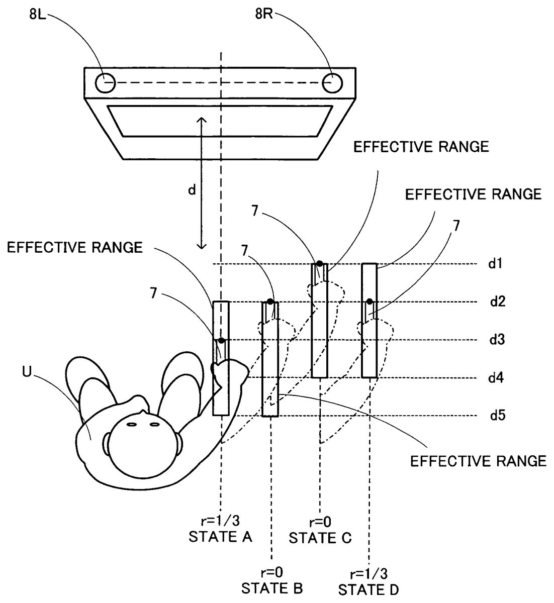
First, the effective range will be described. The effective range as used herein refers to a range defined for the position of the controller7with respect to a reference. A value based on the position of the controller7with respect to the effective range is given to the video game program and used in the game process. In the present embodiment, the distance d from the markers8L and8R to the tip of the controller7is used as the value representing the position of the controller7. Therefore, the effective range is defined with respect to the distance d, with the lower limit of the effective range being 0 and the upper limit thereof being 1. A value between 0 to +1 according to the position of the controller7in the effective range is selected as the value according to the position of the controller7. For example, the width of the effective range is determined to be a width across which the player can reasonably swing the controller7held in the player's hand without moving the feet, e.g., about 10 cm to about 40 cm. For example, where the width of the effective range is 30 cm and the distance between the markers8L and8R and the initial position of the controller7is 1 m 15 cm, the effective range is defined to be 1 m to 1 m 30 cm in terms of the distance from the markers8L and8R. Then, the value 0.5, representing the position at a distance of 1 m 15 cm, is used in the game process. While the effective range is defined in the illustrated example so that its center coincides with the position of the controller7, the present invention is not limited thereto, and the effective range can be defined in any manner as long as the initial position of the controller7is included therein.
This will now be described in greater detail with reference toFIGS. 17A and 17B. First,FIG. 17Ashows a case where a player U moves the controller7forward and backward with respect to the markers8L and8R. InFIG. 17A, “d” denotes the distance from the markers8L and8R to the controller7, and “d1”, “d2”, “d3”, “d4” and “d5” each denote the distance from the markers8L and8R to the tip of the controller7.FIG. 17Bshows a positional relationship between the effective range and the controller7, and shows how to obtain the value (the forward/backward position parameter) r to be used in the game process in that position. In the figure, Lr is the width (length) of the effective range, min is the front end position (the distance from the markers8L and8R to the closest end of the effective range), and max is the rear end position (the distance from the markers8L and8R to the farthest end of the effective range), wherein Lr=max−min. In the present embodiment, the effective range is defined so that the forward/backward position parameter r is calculated to be 0 when the controller7(strictly speaking, the image sensing device743) is located at the effective range front end position min. The forward/backward position parameter r is calculated to be 1 when the controller7is located at the effective range rear end position max. The forward/backward position parameter r is calculated to be a value between 0 and 1 according to the position of the controller7when the controller7is between the front end position min and the rear end position max of the effective range. When the player holding the controller7moves the controller7forward/backward beyond the effective range, the effective range is instantly moved so that the new position of the controller7is the front end position min or the rear end position max.
Specifically, where the controller7is at a distance d3 and the effective range is defined to extend from a distance d2 to a distance d5 as shown in state A ofFIG. 17A, the value r corresponding to the distance d3 in the effective range where the distance d2 is 0 and the distance d5 is 1 is calculated to be ⅓ (0.33), for example. The value r is used in the game process. As the controller7is moved from the position at the distance d3 to the position at the distance d2 as shown in state B, the value r is calculated to be 0.33 to 0 according to the movement. As the controller7is further moved to the position at a distance d1 as shown in state C, the effective range is moved along with the movement of the controller7, and the value r remains to be 0. Then, as the controller7is moved from the position at the distance d1 to the position at the distance d2 as shown in state D, the effective range remains unchanged, and the value r according to the position of the controller7in the effective range is calculated to be ⅓ (0.33), for example.
Referring toFIG. 15, the process of calculating the forward/backward position parameter r and re-defining the effective range will be described. Referring toFIG. 15, the CPU30determines whether or not the distance d calculated in step65is shorter than the front end position min (step91), and whether or not the distance d is longer than the rear end position max (step92). If the CPU30determines that the distance d is shorter than the front end position min (a transition from state B to state C inFIG. 17A), the process proceeds to step93. If the CPU30determines that the distance d is longer than the rear end position max, the process proceeds to step94. If the CPU30determines that the distance d is within the effective range (i.e., if the distance d is equal to or greater than the front end position min and equal to or less than the rear end position max) (state A or state D ofFIG. 17A), the process proceeds to step95while the effective range remains unchanged.
In step93, in response to the movement of the controller7to a position exceeding the effective range in the forward direction, the CPU30re-defines the effective range, and proceeds to step95. Specifically, the CPU30updates the effective range front end position min to the current distance d and the rear end position max to the current distance d plus the length Lr, and stores the updated values in the main memory33. In step94, in response to the movement of the controller7to a position exceeding the effective range in the backward direction, the CPU30re-defines the effective range, and proceeds to step95. Specifically, the CPU30updates the effective range rear end position max to the current distance d, and the front end position min to the current distance d minus the length Lr, and stores the updated values in the main memory33. With the provision of steps93and94, when the player moves the controller7forward/backward beyond the effective range, the effective range is instantly moved so that the new position of the controller7is the front end position min or the rear end position max.
In step95, the CPU30calculates the forward/backward position parameter r according to the distance d and the effective range, and exits the subroutine. Specifically, the CPU30calculates the forward/backward position parameter r as follows.
r=(d−min)/Lr
In step95, the forward/backward position parameter r is calculated to be a value between 0 to 1 according to the effective range and the position of the controller7.
Referring back toFIG. 13, after the process of calculating the forward/backward position parameter and re-defining the effective range in step66, the CPU30sets the depth position data z according to the forward/backward position parameter r (step67), and proceeds to the next step. The depth position data z is a value for calculating a coordinate in the depth direction in the game space, and is stored in the main memory33as the depth position data Dc4.
In a case where a player character P is moved by increasing/decreasing the z coordinate value in the camera coordinate system of the virtual camera in a game using a three-dimensional virtual space as shown inFIGS. 18 and 19, for example, the z coordinate value in the camera coordinate system is used as the depth position data z. A predetermined range is defined for the z coordinate, and the z coordinate value is determined so as to correspond to the value of the forward/backward position parameter r with respect to the defined range. With the x coordinate and the y coordinate, in addition to the z coordinate of the camera coordinate system, the position (coordinates) of the player character P in the world coordinate system is determined based on a predetermined conversion function, and the obtained position (coordinates) is stored in the main memory33as the object position data Dc2. The x coordinate and the y coordinate may be predetermined fixed values, or may be calculated from the control input through a process to be described later. In the example shown inFIG. 18, the x coordinate value and the y coordinate value are independent of the movement in the depth direction. Therefore, when the player character P is moved in the game space according to the depth position data z without changing the x coordinate value and the y coordinate value, the player character P moves in a direction parallel to the viewing direction of a virtual camera C. In the example shown inFIG. 19, the x coordinate value and the y coordinate value are changed according to the z coordinate value so that the player character P is displayed at the same position on the screen after a movement in the depth direction.
Where the axis direction of the camera coordinate system is the same as that of the world coordinate system, the z coordinate value in the world coordinate system may be used as the depth position data z throughout the entire process. A predetermined range is defined for the z coordinate, and the z coordinate value is determined so as to correspond to the value of the forward/backward position parameter r with respect to the defined range. Then, the depth position data z can be used as it is as the z component of the object position data Dc2, whereby there is no computational cost for coordinate conversion. Thus, if there is an axis extending in the movement direction, a coordinate component in the world coordinate system or the camera coordinate system may be used as the depth position data z.
If there is no axis extending in the movement direction, a predetermined parameter for the depth direction may be used as the depth position data z throughout the entire process. A predetermined range is defined in the world coordinate system extending in the movement direction including the depth direction component, with the depth position data z being defined as a parameter representing a position in the range, and the object position data Dc2is calculated by a predetermined function. Therefore, in this case, the depth position data z may be the forward/backward position parameter r itself.
Then, the CPU30calculates the pointed position data (step68), and exits the subroutine. The CPU30calculates the pointed position data Dc3by using the direction data Db1and the middle point data Db2calculated in step64, and stores the calculated data in the main memory33.
For example, assume a case where the two markers8L and8R are installed on the upper surface of the monitor2(seeFIG. 7), and the player points at the center of the screen of the monitor2using the controller7whose upper surface is facing up (where the center of the screen is being at the center of the image captured by the image capturing/processing section74). Then, in the image captured by the image capturing/processing section74, the middle point of the target image (the middle point between the markers8L and8R) does not coincide with the pointed position (the center of the screen). Specifically, the position of the target image in the captured image is shifted upward off the center of the captured image. If a reference position is set so that the center of the screen is pointed at when the target image is at such a position, the position of the target image in the captured image moves in response to the movement of the controller7(in the opposite direction to that of the movement of the controller7). Therefore, it is possible to point at a position in the screen corresponding to the movement direction of the controller7by performing a process in which the pointed position in the screen is moved according to the movement of the position of the target image in the captured image. As to the reference position setting, the player may point at a predetermined position on the screen so that the position of the target image at that time is stored while being associated with a reference pointed position. Alternatively, the reference position may be a predetermined position if the positional relationship between the target image and the screen is fixed. The pointed position is calculated by using a function for calculating the coordinates of a position (the pointed position data Dc3) on the screen of the monitor2from the middle point data Db2. The function converts the middle point position (coordinates) calculated from a captured image to a position on the screen being pointed at by the controller7(pointed position) at the time when the image is captured. With this function, it is possible to calculate a pointed position on the screen from a middle point position. In order to convert a middle point position to a position in the game space, a position on the screen calculated by the above function can be further converted to a position in the game space corresponding to the position on the screen. The position in the game space corresponding to the position on the screen may be the position in the game space that is displayed at the position on the screen, the three-dimensional coordinate values in the game space determined by the pointed position data Dc3and the depth position data Dc4, etc.
However, if the player points at the center of the screen of the monitor2using the controller7whose upper surface is not facing up (e.g., facing to the right), the position of the target image in the captured image is shifted off the center of the captured image in a direction other than the upward direction (e.g., to the left). Thus, due to a tile of the controller7, the movement direction of the controller7does not coincide with the movement direction of the pointed position in the screen. In view of this, the middle point data Db2is corrected based on the direction data Db1. Specifically, the middle point data Db2calculated in step64is corrected to a middle point position that would be obtained if the upper surface of the controller7were facing up. More specifically, a direction data reference is also set in the reference position setting process, and the middle point data Db2calculated in step64is corrected by rotating the position represented by the middle point data Db2about the center of the captured image by an amount according to the angular difference between the direction data Db1and the reference direction. Then, the pointed position data Dc3is calculated using the corrected middle point data Db2.
An essential principle of the process of calculating the pointed position data Dc3is to calculate the displacement of a two-dimensional position to be specified with respect to a predetermined reference position based on a change in the position of the target image in response to the movement of the controller7. Therefore, the process of calculating the pointed position data Dc3(step66) can be used not only as a coordinate input corresponding to a position in the screen, but can be used widely as a two-dimensional coordinate input. For example, where the depth position data Dc4is the z coordinate value in the world coordinate system as described above with reference toFIGS. 18 and 19, the pointed position data Dc3can be used as the x coordinate value and the y coordinate value in the world coordinate system to thereby define a three-dimensional position. The pointed position data calculation process in that case may be performed by, irrespective of the screen, performing a calculation process of associating a movement of the target image with a movement of the x coordinate and the y coordinate in the world coordinate system from the reference position. The pointed position data calculation process does not have to be performed in a case where inputs other than that in the depth direction are not necessary, e.g., where the x coordinate value and the y coordinate value are predetermined fixed values.
Referring back toFIG. 12, after the process of calculating the control status information, the pointed position data and the depth position data in step52, the CPU30defines a controlled object controlled with the controller7(step53), and proceeds to the next step. The CPU30defines a controlled object for each of the control section72, the image capturing/processing section74, the acceleration sensor701, etc., provided in the controller7.
For example, a controlled object is updated as necessary in response to advancements in the game and the player's control operation. For example, a controlled object to be controlled based on a signal from the image capturing/processing section74provided in the controller7, i.e., an object to be controlled based on values of the pointed position data Dc3, the depth position data Dc4, etc., may be the object present at a position in the virtual game world that is obtained by converting the pointed position or the depth position. There may be cases where other objects are controlled at the same time by using control means other than the signal from the image capturing/processing section74. For example, the controlled object to be controlled by the cross-shaped key72aprovided on the controller7may be one of the objects in the virtual game world that are being displayed on the monitor2.
In other examples, where it is not necessary to dynamically update a controlled object, the controlled object may be defined statically. For example, a controlled object to be controlled based on a signal from the image capturing/processing section74provided in the controller7may be statically defined to be a player character in the virtual game space, the virtual camera for displaying the virtual game space on the screen, or the like. Where the controlled object is defined statically, it does not have to be defined repeatedly for each iteration of a loop, in which case step53may be performed only at the initialization process of the game process.
Then, the CPU30performs an operation for a controlled object (step54). In step54, the CPU30updates the orientation data Dc1and the object position data Dc2of the controlled object defined in step53. For example, three-dimensional coordinates are calculated based on the pointed position data Dc3and the depth position data Dc4, and the object position data Dc2is updated with the calculated coordinates. Where the position values except for the depth value are statically defined, the three-dimensional coordinates may be calculated from the defined values and the depth position data Dc4. Where the controlled object of the image capturing/processing section74provided in the controller7is a player character, an object in the game space or a virtual camera, the player character, the object or the virtual camera is moved to the position represented by the object position data Dc2. The orientation data Dc1is calculated and updated as necessary in response to the movement. Where the controlled object is the virtual camera, the orientation data Dc1of the virtual camera may be updated so that the position represented by the object position data Dc2is the point of sight. Also with objects to be controlled by control means other than the image capturing/processing section74, a process is performed based on a control operation.
Then, the CPU30performs a display process (step56), and proceeds to the next step. The CPU30produces a game image referring to the controlled object information Dc and other data necessary for producing the game image (e.g., data representing the image and the position of the player character, and the terrain data) which are stored in the main memory33. Specifically, the CPU30produces an image of an object whose position and orientation have been updated in step54, or an image of the virtual space as viewed from a virtual camera whose position and orientation have been updated. Then, the CPU30displays the produced image on the screen of the monitor2.
Then, the CPU30determines whether or not to end the game (step57). For example, the game is ended when a game-over condition is met (e.g., when the parameter representing the player character's remaining physical strength becomes 0) or when the player manually ends the game. If the game is not to be ended, the CPU30returns to step51to repeat the process. If the game is to be ended, the CPU30exits the process shown in the flow chart.
Thus, by capturing the image of fixedly-installed markers (infrared light from the two markers8L and8R in the illustrated example) with the image capturing/processing section74of the controller7, it is possible to realize a novel control device capable of a three-dimensional input operation of specifying not only the position of the controller7in the up/down direction and the left/right direction with respect to the markers, but also the distance between the markers and the controller7. While the range for the input of the distance between the markers and the controller7may extend over quite a large distance, an appropriate effective range is defined depending on the player's current operating position, thereby allowing for an appropriate input suitable for the game process while following changes in the distance. Since the effective range is moved according to the player's current operating position, the player can get a similar operation feel no matter where the player operates the controller7, thus increasing the freedom of the position at which the player performs a control operation. In the present embodiment, when the controller7is moved forward/backward beyond the effective range, the effective range is moved instantly according to the position of the controller7. Therefore, the present embodiment is suitable for a game process in which there should be a high sensitivity to the distance between the controller7and the markers.
Second Embodiment
A video game system according to a second embodiment of the present invention will now be described. The video game system of the second embodiment is similar to that of the first embodiment in terms of the system configuration and the operation, except for the process of calculating the forward/backward position parameter r and re-defining the effective range (see step66ofFIG. 13). Therefore, in the following description of the second embodiment, like elements/steps to those of the first embodiment will be denoted by like reference numerals/step numbers, and will not be further described.
Referring toFIGS. 20 to 22B, the process of calculating the forward/backward position parameter and re-defining the effective range of the second embodiment will now be described in detail.FIG. 20shows, in detail, a subroutine for the process of calculating the forward/backward position parameter and re-defining the effective range according to the present embodiment.FIG. 21shows, in detail, a subroutine of step106inFIG. 20for the rounding process.FIGS. 22A and 22Bshow the operation of calculating the forward/backward position parameter r and defining the effective range according to the subroutine shown inFIG. 20.
Referring toFIGS. 22A and 22B, the effective range used in the second embodiment will first be described. As in the first embodiment, the effective range is a range defined for obtaining the forward/backward position parameter r used in the game process in response to a player's operation in which the player holding the controller7moves the controller7toward or away from the markers8L and8R, i.e., an operation such that the distance d is changed. Therefore, in the process of the present embodiment, the value used as the position of the controller7is specifically the value of the distance d at that time. The effective range is a range with respect to the distance d, wherein Lr is the length of the effective range, min is the front end position (the distance from the markers8L and8R to the closest end of the effective range), and max is the rear end position (the distance from the markers8L and8R to the farthest end of the effective range). Thus, Lr=max−min.
The effective range is defined so that the forward/backward position parameter r is calculated to be 0 when the controller7(strictly speaking, the image sensing device743) is located at the effective range front end position min (e.g., state B ofFIG. 22A). The forward/backward position parameter r is calculated to be 1 when the controller7is located at the effective range rear end position max. The forward/backward position parameter r is calculated to be a value between 0 and 1 according to the position of the controller7when the controller7is between the front end position min and the rear end position max of the effective range (e.g., state A ofFIG. 22A).
In the present embodiment, a play range having a length of p is provided at both ends of the effective range. The effective range is not moved even when the controller7is moved beyond the effective range if the controller7is within the play range, which is provided at both ends of the effective range to be continuous with the effective range. The play range is defined so that the forward/backward position parameter r is calculated to be 0 when the controller7is located in the play range at the front end of the effective range (e.g., state C ofFIG. 22A). The forward/backward position parameter r is calculated to be 1 when the controller7is located in the play range at the rear end of the effective range. Thus, when the player holding the controller7moves the controller7into a play range at the front or rear end of the effective range, the forward/backward position parameter r is calculated to be equal to the front end position min or the rear end position max, whichever is being the boundary between the play range and the effective range.
Even though the controller7being within a play range means that the controller7has been moved forward/backward beyond the effective range, the effective range will not be moved as long as the controller7is located within the effective range or the play range (e.g., a transition from state C to state D inFIG. 22A). When the player holding the controller7moves the controller7to a position beyond the play range, the effective range is moved instantly so that the new position of the controller7is the front end position min or the rear end position max (e.g., a transition from state C to state E inFIG. 22A).
Referring toFIG. 20, the process of calculating the forward/backward position parameter r and re-defining the effective range will be described. Referring toFIG. 20, the CPU30determines whether or not the distance d calculated in step65(seeFIG. 13) is shorter than the front end position min minus p (step101; whether or not the controller7is beyond the end of the front-side play range) and whether or not the distance d is longer than the rear end position max plus p (step102; whether or not the controller7is beyond the end of the rear-side play range). If the CPU30determines that the distance d is shorter than the front end position min minus p (a transition from state C to state E inFIG. 22A), the process proceeds to step103. If the CPU30determines that the distance d is longer than the rear end position max plus p, the process proceeds to step104. If the CPU30determines that the distance d is within the effective range or the play range (i.e., if the distance d is equal to or greater than the front end position min minus p and equal to or less than the rear end position max plus p) (state A to state D ofFIG. 22A), the process proceeds to step105while the effective range remains unchanged.
In step103, in response to the movement of the controller7beyond the front-side play range, the CPU30re-defines the effective range, and proceeds to step105. Specifically, the CPU30updates the effective range front end position min to the current distance d and the rear end position max to the current distance d plus the length Lr, and stores the updated values in the main memory33. In step104, in response to the movement of the controller7beyond the rear-side play range, the CPU30re-defines the effective range, and proceeds to step105. Specifically, the CPU30updates the effective range rear end position max to the current distance d, and the front end position min to the current distance d minus the length Lr, and stores the updated values in the main memory33. With the provision of steps103and104, when the player moves the controller7forward/backward beyond the play range, the effective range is instantly moved so that the new position of the controller7is the front end position min or the rear end position max.
In step105, the CPU30calculates the forward/backward position parameter r according to the distance d and the effective range. Then, the CPU30performs a process of rounding the calculated value of the forward/backward position parameter r (step106), and exits the subroutine. Specifically, in step105, the CPU30calculates the forward/backward position parameter r as follows.
r=(d−min)/Lr
Then, in the process of step106, the forward/backward position parameter r is rounded to a number between 0 and 1 according to the position of the controller7with respect to the effective range and the play range.
The rounding process will be described with reference toFIG. 21. The CPU30determines whether or not the calculated forward/backward position parameter r is smaller than 0 (step111) and whether or not the calculated forward/backward position parameter r is larger than 1 (step112). If the forward/backward position parameter r is smaller than 0, the CPU30sets the forward/backward position parameter r to 0 (step113), and exits the subroutine. If the forward/backward position parameter r is larger than 1, the CPU30sets the forward/backward position parameter r to 1 (step114), and exits the subroutine. If the forward/backward position parameter r is greater than or equal to 0 and less than or equal to 1, the CPU30exits the subroutine without changing the value r.
Thus, also in the second embodiment, while the range for the input of the distance between the markers and the controller7may extend over quite a large distance, an appropriate effective range is defined depending on the current operating position, thereby allowing for an appropriate input suitable for the game process while following changes in the distance. Since the effective range is moved according to the player's current operating position, the player can get a similar operation feel no matter where the player operates the controller7. With the provision of the play range at both ends of the effective range, it is possible to realize an operation feel different from that of the first embodiment. For example, in the first embodiment, when the controller7is moved forward/backward beyond the effective range, the effective range is instantly moved according to the new position of the controller7. Thus, the position of the effective range is sensitive to the distance between the controller7and the markers. In the second embodiment, with the provision of the play range at both ends of the effective range, there is provided a margin for the movement of the effective range. Specifically, the player may possibly move the controller7over a greater distance than intended, which may result in the controller7being moved beyond the effective range even though the player does not intend to change the operating position. Even in such a case, the effective range is not moved as long as the controller7is within the play range in the second embodiment, whereby it is possible to make a distance input with some margin by using the half-fixed effective range.
Third Embodiment
A video game system according to a third embodiment of the present invention will now be described. The video game system of the third embodiment is similar to that of the first embodiment in terms of the system configuration and the operation, except for the process of calculating the forward/backward position parameter r and re-defining the effective range (see step66ofFIG. 13). Therefore, in the following description of the third embodiment, like elements/steps to those of the first embodiment will be denoted by like reference numerals/step numbers, and will not be further described.
Referring toFIGS. 23 to 24B, the process of calculating the forward/backward position parameter and re-defining the effective range of the third embodiment will now be described in detail.FIG. 23shows, in detail, a subroutine for the process of calculating the forward/backward position parameter and re-defining the effective range according to the present embodiment.FIGS. 24A and 24Bshow the operation of calculating the forward/backward position parameter r and defining the effective range according to the subroutine shown inFIG. 23.
Referring toFIGS. 24A and 24B, the effective range used in the third embodiment will first be described. As in the first embodiment, the effective range is a range defined for obtaining the forward/backward position parameter r used in the game process in response to a player's operation in which the player holding the controller7moves the controller7toward or away from the markers8L and8R, i.e., an operation such that the distance d is changed. Therefore, in the process of the present embodiment, the value used as the position of the controller7is specifically the value of the distance d at that time, and the effective range is a range with respect to the distance d. In the present embodiment, the effective range can be extended by a1 in the forward direction and by a2 in the backward direction. The extension lengths a1 and a2 are variables, based on which the effective range is extended/shrunk. Where a1=0 and a2=0, the effective range is not extended, whereby the front end position of the un-extended effective range (the distance from the markers8L and8R to the closest end of the effective range) is min, and the rear end position thereof (the distance from the markers8L and8R to the farthest end of the effective range) is max. Specifically, the front end position is defined as min−a1, the rear end position as max+a2, and the length Lr of the effective range as max−min+a1+a2.
The effective range is defined so that the forward/backward position parameter r is calculated to be 0 when the controller7(strictly speaking, the image sensing device743) is located at the un-extended effective range front end position min minus a1 (e.g., state B ofFIG. 24A). The forward/backward position parameter r is calculated to be 1 when the controller7is located at the un-extended effective range rear end position max plus a2. The forward/backward position parameter r is calculated to be a value between 0 and 1 according to the position of the controller7when the controller7is between the front end position min minus a1 and the rear end position max plus a2 of the un-extended effective range (e.g., state A ofFIG. 24A).
In the present embodiment, a play range having a length of p is provided at both ends, as shown inFIG. 24B. The effective range is not moved (as will later be more apparent, the effective range may be extended/shrunk) even when the controller7is moved beyond the area between min and max if the controller7is within the play range, which is provided next to min and max to be continuous with the effective range.
When the controller7is located within the play range, the extension length a1 or a2 is increased/decreased to extend/shrink the effective range so that the boundary of the effective range approaches the position of the controller7at a predetermined rate. When the controller7is within the play range and is outside the effective range, the extension length a1 or a2 is increased to extend the effective range (e.g., as indicated by an arrow shown in state C ofFIG. 24A). When the controller7is within the play range and within the effective range, the extension length a1 or a2 is decreased to shrink the effective range (e.g., as indicated by an arrow shown in state D ofFIG. 24A). When the controller7is located between min and max, the extension length a1 or a2 is decreased to shrink the effective range so that the boundary of the effective range approaches min and max at a predetermined rate. When the player holding the controller7moves the controller7beyond the play range, the extension length a1 or a2 is equal to the length of the play range, and the entire effective range is moved so that the boundary of the effective range approaches the position of the controller7at a predetermined rate (e.g., state E ofFIG. 24A). Then, the controller7is located outside the effective range and outside the play range, and the value of the forward/backward position parameter r is adjusted by a process similar to the rounding process so that the value is 0 when the controller7is on the front side of the effective range and the play range and the value is 1 when the controller7is on the rear side of the effective range and the play range. While one end of the effective range is extending/shrinking, the other end thereof extends/shrinks independently of the first end unless the effective range itself is being moved (state A to state D ofFIG. 24A).
Referring now toFIG. 23, the process of calculating the forward/backward position parameter r and re-defining the effective range will be described. Referring toFIG. 23, the CPU30determines whether or not the distance d calculated in step65(seeFIG. 13) is greater than or equal to min and less than or equal to max (step121), whether or not the distance d is less than or equal to min−p (step122; whether or not the controller7is beyond the end of the front-side play range), whether or not the distance d is longer than min−p and shorter than min (step123), and whether or not the distance d is greater than or equal to max+p (step124; whether or not the controller7is beyond the end of the rear-side play range). If the distance d is greater than or equal to min and less than or equal to max (state A ofFIG. 24A), the CPU30proceeds to step125. If the distance d is less than or equal to min−p (state E ofFIG. 24A), the CPU30proceeds to step126. If the distance d is longer than min−p and shorter than min (state C and state D ofFIG. 24A), the CPU30proceeds to step127. If the distance d is greater than or equal to max+p, the CPU30proceeds to step128. If the distance d is shorter than max+p and longer than max, the CPU30proceeds to step129.
Instep125, in response to the controller7being located between min and max, the CPU30re-defines the effective range by shrinking it to its original length, and proceeds to step130. Specifically, the CPU30updates the extension length a1 to a1×s (s is a constant satisfying 0<s<=1; the effective range instantly goes back to the original length if s=1) and the extension length a2 to a2×s, and stores the updated values in the main memory33. In step126, in response to the movement of the controller7beyond the front-side play range, the CPU30re-defines the effective range, and proceeds to step130. Specifically, the CPU30updates the extension length a1 to the length p of the play range, the extension length a2 to a2×s, the value min to min−(min−d−a1)×s, and the value max to max−(min−d−a1)×s, and stores the updated values in the main memory33. In step127, in response to the movement of the controller7into the front-side play range, the CPU30re-defines the effective range, and proceeds to step130. Specifically, the CPU30updates the extension length a1 to a1+(min−d−a1)×s and the extension length a2 to a2×s, and stores the updated values in the main memory33. In step128, in response to the movement of the controller7beyond the rear-side play range, the CPU30re-defines the effective range, and proceeds to step130. Specifically, the CPU30updates the extension length a1 to a1×s, the extension length a2 to the length p of the play range, the value max to max+(d−max−a2)×s and the value min to min+(d−max−a2)×s, and stores the updated values in the main memory33. In step129, in response to the movement of the controller7into the rear-side play range, the CPU30re-defines the effective range, and proceeds to step130. Specifically, the CPU30updates the extension length a1 to a1×s and the extension length a2 to a2+(d−max−a2)×s, and stores the updated values in the main memory33. With the provision of steps125to129, the effective range is extended/shrunk and moved at a predetermined speed according to the new position of the controller7.
In step130, the CPU30calculates the forward/backward position parameter r according to the distance d and the effective range. Then, the CPU30performs a process of rounding the calculated value of the forward/backward position parameter r (step131), and exits the subroutine. Specifically, in step130, the CPU30calculates the length Lr as follows
Lr=max−min+a1+a2
and calculates the forward/backward position parameter r as follows.
r=(d−min−a1)/Lr
In step131, the forward/backward position parameter r is rounded to a number between 0 and 1 according to the position of the controller7with respect to the effective range and the play range. The rounding process of step131is similar to that of the second embodiment as described above with reference toFIG. 21, and will not be further described below.
Thus, also in the third embodiment, while the range for the input of the distance between the markers and the controller7may extend over quite a large distance, an appropriate effective range is defined depending on the current operating position, thereby allowing for an appropriate input suitable for the game process while following changes in the distance. Since the effective range is moved according to the player's current operating position, the player can get a similar operation feel no matter where the player operates the controller7. With the provision of the play range at both ends of the effective range, and with the effective range being extended/shrunk at a predetermined rate and moved at a predetermined rate, it is possible to realize an operation feel different from that of the first or second embodiment. For example, in the first and second embodiments, when the controller7is moved forward/backward beyond the effective range or beyond the play range, the effective range is instantly moved according to the new position of the controller7. Thus, the position of the effective range is sensitive to the distance between the controller7and the markers. In the third embodiment, with the provision of the play range at both ends of the effective range and with the effective range being extended/shrunk or moved gradually, the effective range reacts even more slowly to a player's input. Even if the player unintentionally makes an abrupt, erroneous movement, thereby moving the controller7forward/backward beyond the effective range, the effective range will be following the operating position only gradually. Therefore, the influence of the erroneous operation can be absorbed to some extent. If the player changes the position of the controller7intending to move the effective range, the effective range is moved appropriately. Thus, it is possible to realize a more stable input operation.
While the effective range is defined so that it is possible to make an input specifying the distance between the markers and the controller7by capturing the image of fixedly-installed markers with the image capturing/processing section74of the controller7, it may alternatively be defined so that a position in other directions can be specified based on the captured image. For example, in order to specify the position of the controller7with respect to the markers in the left/right direction or that in the up/down direction (e.g., the pointed position data Dc3), an effective range may be defined to extend in each of these directions. Then, a left/right or up/down position parameter can be calculated based on the positional relationship between the position of the controller7in the left/right direction or the up/down direction and the effective range. It is possible to define an effective range for making an input specifying a position in other directions by moving or extending/shrinking the effective range according to the position of the controller7in the left/right direction or the up/down direction, as with the distance direction as described above.
This variation can be realized in the form of a video game program as follows. The video game program is a video game program executed by a computer (30) of a video game device (3) for performing a game process by obtaining, as control data (Da), data (Da1, Da2) from a game controller (7) including an image-capturing section (74) for capturing an image of an imaging target (8), the data (Da1, Da2) being either the captured image itself from the image-capturing section or data obtained by performing a predetermined operation on the captured image. The video game program instructs the computer to perform a position detection step, an effective range defining step, a position data calculation step, a game process step and a display process step. The position detection step uses the control data obtained from the game controller to detect at least one of the position of the game controller with respect to the imaging target in the up/down direction and that in the left/right direction, based on the position of the imaging target in the captured image. The effective range defining step defines an effective range having a predetermined length along at least one of the up/down direction and the left/right direction with respect to the game controller. The position data calculation step calculates position data regarding the position in at least one of the up/down direction and the left/right direction, according to the position of the game controller with respect to the effective range. The game process step performs a predetermined game process on the virtual game world based on the position data calculated in the position data calculation step. The display process step displays, on a display device, an image of the virtual game world after the game process. The video game program may instruct the computer to further perform an effective range re-defining step. When the position of the game controller goes beyond the effective range, the effective range re-defining step re-defines the effective range by moving the effective range according to the new position of the game controller.
While the forward/backward position parameter r is converted to the depth position data z in the game process described above, the forward/backward position parameter r may be used in various types of game processes. In an alternative game process, the forward/backward position parameter r may be converted to the speed of an object in the virtual game world, such as a vehicle. In another game process, the forward/backward position parameter r may be used as a parameter for an action (e.g., throwing a punch) executed by a player character in the virtual game world. In another game process, the forward/backward position parameter r may be converted to the zoom factor of the virtual camera. In another game process, at least one threshold value may be set for the forward/backward position parameter r so as to provide a switch that is turned ON/OFF based on the value r with respect to the threshold value (e.g., a predetermined action of a player character may be triggered based on the value r with respect to the threshold value).
While the distance d is calculated by analyzing the image data obtained by the image sensing device743in the above description, the present invention can be carried out with any other suitable means as long as the distance d to a predetermined measured target placed in a real space can be determined, whereby an effective range can be defined for the distance d. The means for determining the distance d may be, for example, those using an ultrasonic sensor, a magnetic sensor, etc. It is possible to make a control input, without determining the actual distance d between the image sensing device743and the imaging target, as long as it is possible to obtain a value associated with the distance. Therefore, without determining the distance d, the process can be performed by using data provided in advance and associated with the length between the markers8L and8R in the captured image.
While the controller7and the video game device3are connected to each other via wireless communications in the above description, the controller7and the video game device3may be electrically connected to each other via a cable. In such a case, a cable connected to the controller7is connected to a connection terminal of the video game device3.
While the receiver unit6connected to the connection terminal of the video game device3is used as receiver means for receiving transmit data wirelessly transmitted from the controller7in the above description, the receiver means may alternatively be a receiver module provided inside the video game device3. In such a case, the transmit data received by the receiver module is outputted to the CPU30via a predetermined bus.
In the above description, the image data captured by the image sensing device743is analyzed, whereby the position of infrared light from the markers8L and8R, the centroid thereof, etc., are produced in the controller7as process result data, and the produced process result data is transmitted to the video game device3. Alternatively, data at any other suitable process step may be transmitted from the controller7to the video game device3. For example, the image data captured by the image sensing device743may be transmitted from the controller7to the video game device3, wherein the CPU30performs the analysis process to obtain the process result data. In such a case, there is no need for the image processing circuit744provided in the controller7. Alternatively, data at a certain point during the process of analyzing the image data may be transmitted from the controller7to the video game device3. For example, data obtained from the image data representing luminance, position, area, etc., may be transmitted from the controller7to the video game device3, wherein the CPU30performs the rest of the analysis process to obtain the process result data.
While infrared light from the two markers8L and8R are used as imaging targets to be captured by the image capturing/processing section74of the controller7in the above description, any other suitable object may be used as the imaging target. For example, only one marker or three or more markers may be provided around the monitor2, and the infrared light from these markers may be used as imaging targets to be captured by the image capturing/processing section74. For example, one marker having a predetermined length may be provided around the monitor2, wherein the present invention can be carried out as described above by using the length of the marker as the interval m (seeFIG. 16). Alternatively, the display screen of the monitor2itself or other light-emitting objects (e.g., lighting in the room) may be used as the imaging target to be captured by the image capturing/processing section74. Any of various light-emitting objects may be used as the imaging target to be captured by the image capturing/processing section74, by calculating the position of the controller7with respect to the display screen based on the positional relationship between the imaging target and the display screen of the monitor2.
The shape of the controller7, and the shape, number and arrangement of the control sections72provided on the controller7, are all illustrative, and it is understood that the present invention can be carried out with any other suitable shape, number and arrangement. The position of the image capturing/processing section74in the controller7(the light receiving port of the image capturing/processing section74) does not have to be the front side of the housing71, but may be on any other side as long as light can be received from outside the housing71.
The storage medium storing a video game program of the present invention is useful, for example, as a video game program of a video game in which a player holds and operates a physically-separate controller unit, and by which it is possible to realize a control operation with a high degree of freedom.
While the invention has been described in detail, the foregoing description is in all aspects illustrative and not restrictive. It is understood that numerous other modifications and variations can be devised without departing from the scope of the invention.
Claims
- A method for performing a process using a controller and a video display device including a processor, the method comprising: providing a reference structure having a known and constant spatial dimension;obtaining control data including at least one of image data captured by an image sensor in the controller of the known and constant spatial dimension of the reference structure and data determined by an analysis of the image data;calculating a first distance representative of a real space distance between the controller and the reference structure;defining an effective range as between a first distance from the reference structure to a second distance from the reference structure, wherein the effective range is defined to include the calculated first distance between the controller and the reference structure;calculating an effective range position representing a position of the controller within the effective range using the defined effective range and a calculated second distance representative of a real space distance between the controller and the reference structure;performing a process in the virtual world through an operation using data representative of the effective range position data, and displaying the virtual world after performing the process.
- The method of claim 1 further comprising: determining the effective range position data to be a maximum value when the first distance equals the first value, and determining the effective range position data to be a minimum value when the first distance equals the second value.
- The method of claim 1 wherein the first distance is calculated based on an interval between two points in the image data wherein the two points correspond to points on the measured reference structure separated by the known physical dimension.
- A storage medium storing a video game program to be executed by a computer of a video game device for performing a game process by obtaining control data from a game controller, wherein the storage medium is a non-transitory storage medium and the video game program instructs the computer to perform: a distance data calculation including calculating distance data associated with a distance between the game controller and a constant measured reference structure provided in a real space, by using the control data obtained from the game controller, wherein the measured reference structure has a constant measured spatial dimension and the control data includes information of a view from the perspective of the game controller of the constant measured spatial dimension;defining an effective range which includes the calculated distance and is based on a first distance value greater than the calculated distance and a second distance value shorter than the calculated distance;calculating effective range position data representing at least one position of the game controller in the effective range based on a calculation of a second distance between the game controller and the constant measured reference structure, wherein the calculation of the second distance occurs after the definition of the effective range;a game process including performing a game process on a virtual game world through an operation based on the effective range position data;and a display process including displaying, on a display device, the virtual game world after the game process.
- The storage medium storing a video game program according to claim 4 , wherein: the game controller includes an image-capturing section for capturing an image of an imaging target;the control data includes a captured image of the measured reference structure, which image is captured by the image-capturing section or a result of performing an operation on the captured image;and the distance data calculation includes a calculation of the distance data by using the captured image or the result of performing an operation on the captured image included in the control data.
- The storage medium storing a video game program according to claim 5 , wherein the calculation of the distance data includes calculating the distance data based on an interval between at least two points that are indicated by the imaging target in the captured image.
- The storage medium storing a video game program according to claim 5 , wherein: the video game program instructs the computer to further determine a pointed position as a position in a display area of the display device based on a position of the imaging target in the captured image;and the game process further includes performing a game process on the virtual game world based on the pointed position.
- The storage medium storing a video game program according to claim 4 , wherein the calculation of the effective range position data includes calculating the effective range position data so that the effective range position data takes a maximum value when the value of the distance data is equal to the first distance value and a minimum value when the value of the distance data is equal to the second distance value.
- The storage medium storing a video game program according to claim 4 , wherein the game process includes: obtaining a depth direction position in a three-dimensional virtual game space corresponding to the effective range position data;performing a game process including an operation using the depth direction position, and wherein the display process step includes displaying, in a display area of the display device, a three-dimensional virtual game space that has undergone a game process in the game process step.
- The storage medium storing a video game program according to claim 4 , wherein the game controller is portable.
- The storage medium storing a video game program according to claim 4 , wherein the game controller is movable relative to the constant measured reference structure during the game process.
- A storage medium storing a video game program to be executed by a computer of a video game device for performing a game process by obtaining control data from a game controller, wherein the storage medium is a non-transitory storage medium and the video game program instructs the computer to perform: calculating distance data associated with a distance between the game controller and a constant measured reference structure provided in a real space, by using the control data obtained from the game controller;performing a game process on a virtual game world through an operation based on a value of the calculated distance data;displaying, on a display device, the virtual game world after the game process;defining an effective range as a range from a first value to a second value;and calculating effective range position data representing a position of the value of the distance data in the effective range, wherein the game process step performs a game process on the virtual game world through an operation based on the calculated effective range position data;wherein the video game program instructs the computer to further perform a first effective range update which, when the value of the distance data is outside the effective range, updates the first value and the second value so that one of the first value and the second value that is closer to the value of the distance data becomes equal to the value of the distance data.
- A storage medium storing a video game program to be executed by a computer of a video game device for performing a game process by obtaining control data from a game controller, wherein the storage medium is a non-transitory storage medium and the video game program instructs the computer to perform: calculating distance data associated with a distance between the game controller and a constant measured reference structure provided in a real space, by using the control data obtained from the game controller;performing a game process on a virtual game world through an operation based on a value of the distance data;displaying the virtual game world after the game process;defining an effective range as a range from a first value to a second value;and calculating effective range position data representing a position of the value of the distance data in the effective range, wherein the game process performing a process on the virtual game world through an operation based on the effective range position data;wherein the video game program instructs the computer to further perform a second effective range update which, when the value of the distance data is outside the effective range, updates the first value and the second value so that one of the first value and the second value that is closer to the value of the distance data approaches the value of the distance data at a predetermined rate.
- A storage medium storing a video game program to be executed by a computer of a video game device for performing a game process by obtaining control data from a game controller, wherein the storage medium is a non-transitory storage medium and the video game program instructs the computer to perform: calculating distance data associated with a distance between the game controller and a constant measured reference structure provided in a real space, using the control data obtained from the game controller;performing a game process on a virtual game world through an operation based on a value of the distance data;displaying the virtual game world after the game process;defining an effective range as a range from a first value to a second value;and calculating effective range position data representing a position of the value of the distance data in the effective range, wherein the game process performs a process on the virtual game world through an operation based on the calculated effective range position data, wherein: the defining of the effective range includes defining a play range having a constant length at a front end of the effective range and a rear end thereof;and the video game program instructs the computer to further perform an effective range update which, when the distance data takes a value outside a combined range including the effective range and the play ranges, updates the first value and the second value so that one of the first value and the second value that is closer to the value of the distance data becomes equal to the value of the distance data.
- The storage medium storing a video game program according to claim 14 , wherein the position data calculation step calculates the effective range position data so that: the effective range position data takes a maximum value when the value of the distance data is equal to the first value or exceeds the effective range in a direction of the first value;and the effective range position data takes a minimum value when the value of the distance data is equal to the second value or exceeds the effective range in a direction of the second value.
- A storage medium storing a video game program to be executed by a computer of a video game device for performing a game process by obtaining control data from a game controller, wherein the storage medium is a non-transitory storage medium and the video game program instructs the computer to perform: calculating distance data associated with a distance between the game controller and a constant measured reference structure provided in a real space, by using the control data obtained from the game controller;performing a game process on a virtual game world through an operation based on a value of the distance data;and displaying the virtual game world after the game process wherein: a first value, a second value smaller than the first value, a third value larger than the first value, and a fourth value smaller than the second value are defined;the video game program instructs the computer to further perform: defining an upper limit value variable from the first value to the third value and a lower limit value variable from the second value to the fourth value, and defining an effective range as a range the from the variable upper limit value to the variable lower limit value;when the value of the distance data is within the variable range of the upper limit value/lower limit value, updating the upper limit value/lower limit value so that the upper limit value/lower limit value approaches the value of the distance data at a predetermined rate and updating the lower limit value/upper limit value so that the lower limit value/upper limit value approaches the second value/first value at a predetermined rate;when the value of the distance data is within a range between the first value and the second value, updating the upper limit value/lower limit value so that the upper limit value/lower limit value approaches the first value/second value at a predetermined rate;when the value of the distance data is larger than the third value, moving the first value, the second value, the third value, the fourth value and the lower limit value so that the third value approaches the value of the distance data at a predetermined rate and updating the upper limit value to the new third value;when the value of the distance data is smaller than the fourth value, moving the first value, the second value, the third value, the fourth value and the upper limit value so that the fourth value approaches the value of the distance data at a predetermined rate and updating the lower limit value to the new fourth value;and a position data calculation step including calculating effective range position data representing a position of the value of the distance data in the effective range, wherein the game process step performs a game process on the virtual game world through an operation based on the value of the effective range position data calculated in the position data calculation step.
- The storage medium storing a video game program according to claim 16 , wherein the position data calculation step calculates the effective range position data so that: the effective range position data takes a maximum value when the value of the distance data is equal to the first value or is below the effective range in a direction of the first value;and the effective range position data takes a minimum value when the value of the distance data is equal to the second value or exceeds the effective range in a direction of the second value.
- The storage medium storing a video game program according to claim 16 , wherein the game process includes: obtaining a depth direction position in a three-dimensional virtual game space corresponding to the effective range position data;and performing a game process including an operation using the depth direction position, and wherein the display process step includes displaying, in a display area of the display device, a three-dimensional virtual game space that has undergone a game process in the game process step.
- A method for performing a game process using a game controller and a video game device including a processor, the method comprising: providing a reference structure having a known and constant spatial dimension;obtaining control data including at least one of image data captured by an image sensor in the game controller of the known and constant spatial dimension of the reference structure and data determined by an analysis of the image data;calculating a distance representative of a real space distance between the game controller and the reference structure;defining an effective range as a range from a first distance to a second distance;identifying which of the first distance and the second distance is further away from the calculated distance, and redefining the effective range as a range from the calculated distance and the identified first or second distance;performing a game process in the virtual game world through an operation using data representative of calculated distance relative to the effective range, and displaying the virtual game world after performing the game process.
- A method for performing a game process using a game controller and a video game device including a processor, the method comprising: providing a reference structure having a known and constant spatial dimension;obtaining control data including at least one of image data captured by an image sensor in the game controller of the known and constant spatial dimension of the reference structure and data determined by an analysis of the image data;calculating a distance representative of a real space distance between the game controller and the reference structure;defining an effective range as a range from a first value to a second value;if the calculated distance is beyond the effective range, moving at least one of the first value or the second value towards the calculated distance at a predetermined rate;performing a game process in the virtual game world through an operation using data representative of calculated distance relative to the effective range, and displaying the virtual game world after performing the game process.
- The method of claim 20 wherein the moved first value or second value is the value nearest the calculated distance prior to the move.
- A method for performing a game process using a game controller and a video game device including a processor, the method comprising: providing a reference structure having a known and constant spatial dimension;obtaining control data including at least one of image data captured by an image sensor in the game controller of the known and constant spatial dimension of the reference structure and data determined by an analysis of the image data;calculating a calculated distance representative of a real space distance between the game controller and the reference structure;defining an effective range as a range from a first value to a second value;calculating effective range position data representing a position of the calculated distance with respect to the effective range;defining a play range having a constant length, and if the calculated distance is beyond the effective range by a distance greater than the play range, substituting the one of the first value and the second value closest to the calculated data;performing a game process in the virtual game world through an operation using data representative of calculated distance relative to the effective range, and displaying the virtual game world after performing the game process.
- A game apparatus comprising: a reference structure having thereon a known and constant spatial dimension;a game controller having an image capture device, which captures an image of the reference structure;a computer accessing a program stored on a non-transitory memory, the computer executes the program to cause the game apparatus to: obtain control data from the game controller wherein the control data includes the image of the reference structure or data determined by an analysis of the image;calculate a first distance representative of an actual physical distance between the game controller at a first instance and the reference structure;define an effective distance range wherein the first distance between the game controller and the reference structure is within the effective range;after defining the effective distance range, calculate effective range position data at successive times, wherein each successive effective range position data represents a position of the controller with respect to the effective distance range;perform a game process on a virtual game world generated by the computer wherein the game process uses the effective range position data, and display on a display device an image of the virtual game world after the game process is performed.
- The game apparatus as in claim 23 wherein the reference structure is mountable proximate to the display device.
- A system comprising: a display device a reference structure having thereon a known and constant spatial reference dimension, and the reference structure device mounted proximate to the display device;a controller having an image capture device, which captures an image of the reference structure;a console having a computer accessing a program stored on a non-transitory memory in the console, the computer executes the program to cause the console to: obtain control data from the controller wherein the control data includes at least one of the image of the known and constant spatial reference dimension of the reference structure and data determined by an analysis of the image;calculate in real time a calculated distance representative of an actual physical distance between the controller and the reference structure based on the control data;set a range of distances which includes the calculated distance;in response to the calculated distance being beyond the set range of distances, reset the range of distances to include the calculated distance;determine a process position representing the calculated distance relative to the range of distances;perform a process on a virtual world generated by the computer wherein the process uses the process position, and display on the display device an image of the virtual world after the process is performed.
Disclaimer: Data collected from the USPTO and may be malformed, incomplete, and/or otherwise inaccurate.