U.S. Pat. No. 9,550,129
Multiplayer Game Platform For Toys Fleet Controlled By Mobile Electronic Device
Issue DateApril 5, 2016
Illustrative Figure
Abstract
A multi-player game platform comprising: at least one mobile electronic device (MED) comprising a processor and configured to execute programmable commands of a control software application; said at least one MED additionally comprising a display configured to provide GUI (Graphical User Interface) means for receiving user input and providing output to a user, a digital camera and communication components configured to communicate with at least one toy, said at least one MED is one of a master MED, wherein said control software application is a master application and a slave MED, wherein said control software application is a slave application; and at least one electro-mechanical toy wirelessly controlled by the control software application, said toy comprising a CPU, a digital memory, a chassis and at least one sensor, said digital memory configured to store a toy software application configured to manage the toy according to commands from the control software application, wherein said digital camera is configured to capture images of said toys and wherein said display is configured to display said captured images, said GUI comprising means for selecting and controlling toys from said displayed image, said processor comprising image processing means configured to process said captured images.
Description
DETAILED DESCRIPTION OF EMBODIMENTS The present invention provides a multi-player game platform that consists of software applications on mobile electronic devices (MED) and a set of external electro-mechanical devices (toys) wirelessly controlled by the MED application. Each player controls a different fleet of toys consisting of at least one toy. The MED may be any mobile electronic device such as a smart-phone, iphone, android based cellular, tablet, ipad, ipod, google glass or any other programmable device with transceiver. The invention is about implementing a game (or particularly a strategic game) of players managing an event (or particularly tactic war) between their fleets of toys (or particularly their armies) using the software on their MEDs. The toys comprise sensors that improve the game experience. The invention defines methods to implement some elements in the game:Short range communication between toys—which is communication between two toys that works only when the toys are close enough to each other (10-30 cm)Flags stealing using magnetsTactical gaming using the digital memory of the toys and using different types of toys control. Moreover, the invention consists of a new user interface that enables the player to control multiple units in the physical world by seeing their images on his MED screen and pressing the touch screen on his MED. The user interface has two features: 1. Select toys from image—The player turns the MED's camera in a way such that he sees the toys he wants to select. The player selects the toys by clicking their images on the MED's screen. The MED identifies the player selection and then may apply several functions on the selected toys. Examples for possible functions on the selected toys may be: tank shoots, Barbie smiles, light turn on, navigate toy, etc. 2. Navigate units from image—After selecting toys, one of the ...
DETAILED DESCRIPTION OF EMBODIMENTS
The present invention provides a multi-player game platform that consists of software applications on mobile electronic devices (MED) and a set of external electro-mechanical devices (toys) wirelessly controlled by the MED application. Each player controls a different fleet of toys consisting of at least one toy.
The MED may be any mobile electronic device such as a smart-phone, iphone, android based cellular, tablet, ipad, ipod, google glass or any other programmable device with transceiver.
The invention is about implementing a game (or particularly a strategic game) of players managing an event (or particularly tactic war) between their fleets of toys (or particularly their armies) using the software on their MEDs. The toys comprise sensors that improve the game experience. The invention defines methods to implement some elements in the game:Short range communication between toys—which is communication between two toys that works only when the toys are close enough to each other (10-30 cm)Flags stealing using magnetsTactical gaming using the digital memory of the toys and using different types of toys control.
Moreover, the invention consists of a new user interface that enables the player to control multiple units in the physical world by seeing their images on his MED screen and pressing the touch screen on his MED.
The user interface has two features:
1. Select toys from image—The player turns the MED's camera in a way such that he sees the toys he wants to select. The player selects the toys by clicking their images on the MED's screen. The MED identifies the player selection and then may apply several functions on the selected toys.
Examples for possible functions on the selected toys may be: tank shoots, Barbie smiles, light turn on, navigate toy, etc.
2. Navigate units from image—After selecting toys, one of the available functions is navigating the toys to a certain location in the room. The player presses any location on the image. This location represents a line of sight to a location in the physical world. The toys maneuver to this location in the physical world or only turn to the direction of this location. This feature is obviously relevant only for mobile toys.
Referring toFIG. 1, the present invention provides a multi-players100game to be played using several MEDs110and at least one toy120for each player, controlled by the respective MED. Each MED110runs a software application. One of the players' MED is called “Master” and runs a master software application130that manages and initiates the game. The other players' MEDs are “Slaves” and run a slave software application140that has partial functionality of the Master application130. Each of the software applications Master130and Slaves140communicates with toys120which are electro-mechanical devices of various types using long range communication. The toys120communicate between themselves using short range communication. Each toy has its unique operating software125.
In a different embodiment of the software architecture, the master application may run on a server and not on a MED of one of the players. This option enables a more complicated master application and hence a more sophisticated virtual game. Moreover, it enables the game to proceed if the player that holds the MED with the master application leaves the game. However, throughout the following description we assume that the master application is running on the MED of one of the players.
Each toy and each MED is allocated a unique ID by the master when the game is initiated.
The software (130,140) may control each toy at a time or it may control several toys simultaneously. It may deliver the same command to more than one toy, like move forward, or it can deliver a more sophisticated command to more than one toy that will be interpreted differently for each toy, like for example the sophisticated command is to encircle a structure or a specific toy with ID=X and shoot at it. This command will be interpreted as a sequence of commands for each toy to move to a different location and start shooting in its turn by a certain order and timing.
FIG. 2shows a single MED110controlling several exemplary types of toys120:
200—A walking toy like a robot or other mechanical mechanism having 2 or more legs;
210—A floating toy like a boat;
220—A driving toy like a car, a motorcycle, a truck or any other mobile toy with wheels;
230—A flying toy like a helicopter, a plane, a mosquito, a butterfly;
240—A jumping toy like a frog or any other bouncing mechanism (for example based on springs or electro-magnets);
250—A shooting toy a like controlled steering cannon (the shooting method will be explained below);
260—A static toy containing sensors and communication devices (for example, a flag with RFID that transmits a message when a different RFID chip is close to it and a magnet enabling the toy to attach to the other close by toy);
270—A dynamic structure like a gate that can be opened or closed;
280—A static toy with RFID, such as a mine that can be programmed to harm or kill an approaching toy or a reward (e.g. added resources) presented to an approaching toy.
Although the toys, as exemplified inFIG. 2, may vary,FIG. 3depicts the relevant components of each toy120. Not every toy includes all of the sensors300-340; it depends on the functionality of each toy. Each toy has a chassis and a battery345; for example a car, a helicopter, a gate. The toys may also include a mobility mechanism350(for mobile toys) like wheels, rotors, springs, blades, motors355. The toys may include servos360for self movements like opening/closing of a gate, or a steering cannon or a wingtip, or lifting an ax for a walking toy (such as available, for example, from http://www.dfrobot.com/). The toy may also include solenoid365, static or electro-magnets and LEDs370. The LEDs of the toy may blink in a certain frequency, in order to be recognizable by the image processing algorithm. The magnets365can be used to attach a different static metal toy or a toy having a magnet in order to transfer it to another location.
The toy may further be equipped with several types of sensor; for example: a line sensor300that detects a colored line beneath its body (such as QRE1113 line sensor, available from https://www.sparkfun.com/), a camera or light sensor305(chips can be photodiode, photo resistor, light to frequency TSL235R or a CMOS camera module such as available from https://www.sparkfun.com/) that detects photons (in any visible and invisible frequencies) radiated toward it, a force sensor (such as a force sensitive resistor 0.5 available from https://www.sparkfun.com/), that senses the amount of physical force operating on it, a distance sensor325(such as Ultrasonic range finder LV-EZ0 available from http://www.maxbotix.com/) that estimates the distance to the nearest object in front of the sensor, a magnetic sensor330, such as MAGNETOMETER DIGITAL TRIPLE AXIS—HMC5883L, available from https://www.sparkfun.com/products/10494, that senses the magnitude of a magnetic field in the environment of the sensor, a RFID sensor335(such as RFID reader ID-20 available from https://www.sparkfun.com) that detects other RFID chips in its environment and a digital compass340(such as a compass module HMC6352 available from https://www.sparkfun.com/) that indicates the north direction.
Each toy also contains communication components for short range380and for long range385. The long range is aimed to communicate with the MED and the short range is aimed to communicate with other toys only when they are close to each other. The short range communication can be implemented by IR or RF.
The toy transmits to whoever listens (broadcast mode) an IR or RF signal as weak as possible, but still strong enough for being detected in the range of 10-30 cm. Usually transmission spreads in the open air not only for short environment, hence the following method are used:
For IR (in which the beam radiates directionally), transmit diagonally toward the floor (this way the signal can be received only in the near neighborhood of the transmitter).
For RF (in which the beams spread omni-directionally), in the receiver side, check if the RSSI (signal strength register) is higher than a certain threshold. This way the toy that receives the signal knows whether to ignore or do something with the received data according to its distance from the transmitting toy.
The long range communication385can be implemented by Bluetooth or WiFi module that usually exist in any MED, or by IR or RF transceiver that needs an additional device to attach to the MED. Exemplary long range communication modules are Bluetooth modem Bluesmirf silver or XBee pro 60 mw available from https://www.sparkfun.com; or BLE2540 available from http://www.fasttech.com/).
Moreover, the sensors, the communication, and all the other mechanisms described above are controlled by a board388that contains a main controller unit (MCU)390, digital memory395and other relevant electronic components like buses, A2D, D2A, etc. (for example an Arduino board model pro-mini328available from http://www.arduino.cc/ or Beagleboard, available from http://beagleboard.org/hardware). The board388stores the toy's software125that manages the toy according to commands from the software application.
Each toy may additionally comprise a speaker375for playing during the game.
FIG. 4depicts the relevant components of each MED110, comprising: relevant communication chips (Bluetooth410, Wi-Fi420, IR or RF transceiver/transmitter or receiver430that enables control and data transfer to and from the toys. Some components (like IR\RF communication chips) may not originally connect to the MED, hence the chips may be physically separated and connected using a serial wiring usually through the audio jack of the MED. The MED contains the software application of the master130and the slave140that contains the virtual part of the game and the user interface that enables the players100to control their fleet of toys120. Moreover the MED may contain auxiliary devices such as a microphone and/or speaker440that enable receiving voice commands from the players and playing background sounds or music during the game, respectively, an accelerometer and a gyro450that enable the player100to rotate the MED110and use it as a joystick that controls the toys, a touch screen460that enables user friendly buttons for the players and a camera470that enables to acquire the image of the game arena and use the image for mapping the physical game and combining it with the virtual game. The camera may be internal to the MED or external and connected serially or wirelessly to the MED. One method of this combination is the innovative user interface that will be elaborated below.
FIG. 5depicts the connections between the toy software125and software in the game implementation. The master software application130communicates with each of the slave software applications140. The master application130manages the game and also contains all the functions of the slave application which enables its player100to play his fleet of toys. The master application130can run on an external server and not necessary on a MED of one of the players. Each of the master and slave applications (130,140) communicates with all the toys software125. The slave application140of one player100can control a toy software125of another player's toy in order to enable toy “stealing” as a possible element in the game. The software (130,140) implements the virtual part of the game.
An example for this is depicted inFIGS. 9A and 9B, showing exemplary GUI of a hide and seek game, whereFIG. 9Ashows a seeker's GUI900andFIG. 9Bshows a hider's GUI910. Each GUI is divided into a real time image of the arena, as captured by the MED camera (930,935) and a control area (915,920). Both control areas comprise a score board960and direction arrows970for controlling the respective toy's movement. The seeker's control area915may include an additional “Expose” control for asserting discovery of the hider. Note that the real time images of the arena inFIGS. 9A and 9Bare different, assuming different points of view of the same game field.
FIG. 6depicts the main functions of the various software modules.
The main functions of each toy software125consist of:
receiving sensor's300-340signals (125.1);
receiving and sending data from/to other nearby toys using the short range communication380(125.2);
receiving and sending data from\to the MED using the long range communication385(125.4,125.5);
commanding the toy's functions such as servos360to rotate or move in a certain velocity or angle (125.6;
operating the mobility mechanism350to move (forward, backward, left, up or down) (125.5);
turning on and off a LED370in a certain timing or in constant frequency (125.6);
operating a solenoid or electro-magnet365(125.6;
receiving and sending data to/from the toy's MCU memory395(125.7).
Using all these main functions, the toy's software application125can control all the toy's features and also receive data from the toy.
The main functions of the slave software application140consist of:
receiving and sending data from/to the communication components (410,420,430) of the MED (140.1,140.2);
running the dynamic virtual part of the game (140.3), comprising GUI, data and more. For example, if two toys are approaching each other, then a combat between them may be carried out virtually (in software) or if a toy shoots on e.g. a building toy270, the virtual instance of this in the software application (130,140) would be graphical animation of firing on buildings. Moreover, the software applications (130,140) have a graphical user-friendly interface to the players as opposed to a standard toy's remote control.
using the auxiliary devices (440,450,460,470) for the specific game requirements (140.4);
identify toy (140.5);
track toy (140.6);
calculate navigation commands (140.7).
The main functions of the master software application130consist of:
Initiating a game's hardware and software, e.g. initiating variables, resources, number of toys, structures, etc.) (130.1);
searching toys in the arena by sending a general message and waiting for return messages from the toys (130.2);
allocating identities to each toy and sending identity and start messages to slave applications (130.3);
selecting game type: Pre-programmed, Turns, Simultaneous (130.4);
starting/ending/loading/saving or pausing a game (130.5-130.8);
all slave functions for controlling the toys of the player who uses the master MED.
These components and their connections enable a physical game of fleets of toys that is controlled and combined with a virtual game running on the MEDs of the players to occur in any space (like a children's room).
FIG. 7demonstrates a simple exemplary static toy that is designed345as a structure270with one servo360that opens or closes a door700. Moreover, the structure includes a MCU390, a transceiver (380,385) and a RFID chip335that enables it to detect a close by toy (having a RFID chip as well).
FIG. 8demonstrates a simple, exemplary static toy that is designed345as a cannon250. The cannon toy consists of a MCU390, a transceiver (380,385) and a servo360that rotates an arm800with a light sensor305. If another toy with a blinking led370appears in front of the cannon, the light sensor305estimates the blinking frequency and can determine which toy it is shooting at.
Apart from controlling the movements of the toys, the game consists of some elements that may challenge the players.
A first example of a challenging element is a method of stealing a flag from the opponent. The flag260is a static toy with a RFID chip335and a static magnet330. The goal of each player100may be stealing the flags260of his opponents and transferring them into his dynamic structure270. The dynamic structure270(may be a static toy, like a gate for example) consists of a RFID chip335detecting that the flag260is nearby. Toy270sends a message to the appropriate MED110that its player100has succeeded to steal the opponent's flag. This action may affect the virtual game, like for example granting the player points or money.
The short range communication380is between two toys that are close enough (10-30 cm range). If two toys are farther apart than that range their messages won't reach each other. This feature adds a challenging element in the game. Some examples for messages that one toy sends to another close by toy may be: “I shoot at you” or “I heal you” or “I steal resources from you” or “Who are you?” or “I transfer resources to you”. All these possibilities and more are very common in virtual games but new in toy games.
We now describe a method of making the toys control more tactical and sophisticated, whereby the game becomes similar to tactical virtual games.
The MCU390and memory395enable defining a program of commands for the toys. Using140.2,125.2and125.3, the players100can define a sequence of commands for their toys (such as writing a machine code), and this sequence of commands can be stored in the toy's memory395and wait for a command to start applying these commands sequentially. For example, the following sequence of commands for a car toy220can define an infinite movement in circles:
1. Move forward for 0.5 sec
2. Turn right 30 degrees
3. Repeat steps 1-2 for 12 iterations
4. Wait 1 sec
5. Go to step 1 (loop)
For programming a certain track for the toy to move, the player may place a ribbon on the floor and the toy may “learn” the track using its line sensor300.
Another example of a more sophisticated sequence of commands for any shooting toy that rotates until it finds an enemy toy and shoots at it:
1. Turn right 10 degrees
2. Ask (using380): “who is near me?”
3. Wait for a response
4. If the response is from an enemy unit then send message: “I shoot at you”
5. Go to step 1 (loop)
The idea of one toy identifying which toy is in its vicinity can be used not only for shooting but also as seeing or detecting. In the game “hide and seek” a group of toys are the seekers while the other group of toys is hiding. The seeker toys need to “see” the hiding toys.
In a war game, a static or mobile toy may serve as a radar that alerts when a unit is getting near. If a toy has a distance sensor325it can estimate distance to another toy in the game. This information along with information of the camera470of the MED110may provide the software (130,140) information about the coordinates of each toy and hence enable sophisticated commands to the toys like automatically chasing a toy, surrounding a toy/structure, etc.
The automatic chasing is implemented with the information of where the chased toy is, relative to the chaser toy. An improvement for the chaser may be using digital compasses340for both the chaser and the chased toys. The readouts from the digital compass are the absolute direction of the toy (relative to the north). These absolute directions of the chaser and the chased toys are sent to the software (130,140). The software subtracts these angles and returns to the chaser the angle it needs to rotate in order to track the chased toy.
This ability to program toys ahead and store several programs in each toy's memory, enables the players to play in one or more of the following three types of game:
1. Pre-programmed—This type of game is divided into two stages: In the first stage each player writes programs (sequences of commands) for his toys. In this stage there is no physical game; the toys are turned off. The second stage is the activation of the player's programs. In this stage the players are completely passive and only look at the outcome of their programs. All toys of all players are playing simultaneously as they were commanded, e.g. by Logo™ programming:
2. Turns—This type of game is divided into turns for each player (e.g. Dune1™). In one turn, one player or a subgroup of players write programs and run their programs. Meanwhile the other players are on hold (cannot play). When a turn ends for one player (or a subgroup of players) the other players get the control and the first are on hold. Each turn ends when a certain number of commands were given or when the time allocation for one turn has ended.
3. Simultaneous—All the players can control their toys in real-time or by writing a program and running it at the same time. The game runs simultaneously for all players and all toys. For example: Warcraft™, Dune2™, etc.
The virtual part of the game140.3may consist of music, graphics, GUI, score, money and resources management and some other functions like: offer treaty, surrender, chat, buy/sell toys from another player.
FIG. 10demonstrates the first feature of the innovative user interface: selecting toy units from image. The player100sees the instances1000of the real toys120on his MED's touch screen460(as long as the toys are in the field of view of the MED's camera470and clicking on each of the toy's instances1000on the MED's touch screen460implies selecting the toy. The method to implement this feature is based on a computer vision algorithm that recognizes the part of the image around the user click and understands which one of the toys was selected (which toy ID). Once the algorithm determined the toy's ID it can communicate with it using the long range communication transmitter (410-430) and send any command to it. Full elaboration of this algorithm will be detailed below.
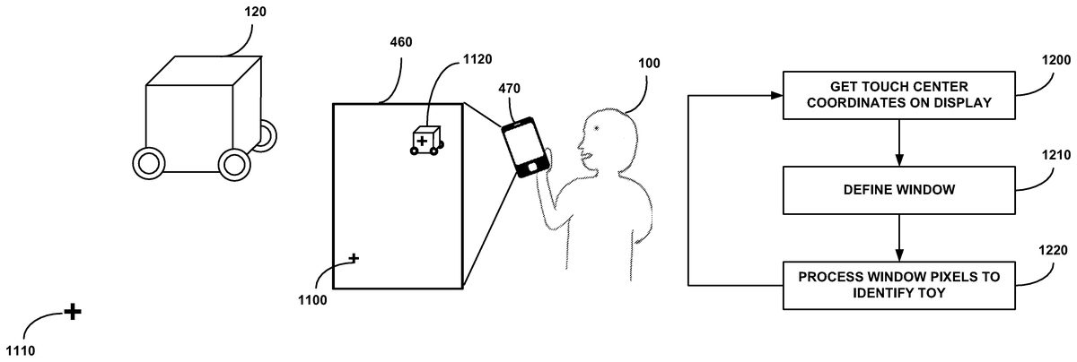
FIG. 11demonstrates the second feature of the innovative user interface: navigating toy units from image. After the player100has selected a toy by clicking its instance1000on the MED's touch screen460, he clicks any point on the touch screen1100that represent a point in the real world (the room)1110. Then the toy120(only for mobile toys) starts maneuvering to the point1110in the room. This feature is based on a navigation algorithm that will be detailed below.
User Interface Algorithms
The algorithms described below are implemented by the MED software (130,140).
The description refers to a single toy and the extension to a fleet of toys is trivial (by applying the same algorithms several times).
Each toy contains a unique physical attribute that enables the algorithm to identify the unit ID from its image (e.g. QR code, marker point, blinking LEDs).
Before the game starts, an initialization process has to be performed with the user\player's cooperation. In this initialization process the algorithm learns the connection between each attribute to each toy ID by asking the player to capture each one of his toys with the MED's camera and provide its ID. Having the unit ID enables sending it data using410-430.
First Feature: Selecting Toy Unit from Image
FIG. 12is a flowchart showing the steps taken by the process of unit selection from the displayed image.
In step1200, the process received the display coordinates of the touch area center.
In step1210the process defines a window of predefined size and shape around the center.
In step1220the pixel inside the window's boundaries are processed in order to identify the selected toy.
Additional toys may now be selected.
Identifying a toy (step1220) may be done using a number of techniques.
For example:
1) Unit identifying based on classic image recognition algorithms like QR code (e.g. http://www.codeproject.com/Articles/20574/Open-Source-QRCode-Library), or feature\descriptors extracting and classification, (e.g. http://vis-www.cs.umass.edu/papers/local_global_workshop.pdf, or http://www.vision.caltech.edu/Image_Datasets/Caltech101/grauman_da rrell_iccv05.pdf, or http://www.imagefeatures.org/), all above resources incorporated herein by reference in their entirety.
2) Unit identifying based on number of blinking LEDs per time unit.
The process is detailed in the flowchart ofFIG. 13.
In step1300an image of the scene is captured; In step1310the process detects blobs inside the window's boundaries of the captured image detected in step1210. Possible implementations: grouping on image over threshold, Gaussian based, Laplacian based, Hessian based. (e.g. http://www.v3ga.net/processing/BlobDetection/index-page-download.html or http://www.cs.illinois.edu/˜slazebni/spring11/lec08_blob.pdf or http://www.openprocessing.org/sketch/10834), all above resources incorporated herein by reference in their entirety. In step1320the process counts the number of detected blobs in the processed window.
Steps1300through1320are repeated as long as additional frames are required1330, as determined in the initialization process according to the types and number of toys.
In step1340the process computes a histogram of the number of blobs (lightened LEDs) for each frame and in step1350the computed histogram is compared to similar toy histograms stored in the system database created during the initialization stage, using any classical metric (minimal square error, cross-correlation, difference in Fourier domain, etc). The best match determines the toy's ID (step1360).
FIG. 14shows two exemplary toy histograms showing number of lit LEDs for each frame, i.e. timing sequence of LEDs blinking.
3) Unit identifying based on a lightened pattern.
Using any pattern with various colors\gray levels (the higher the histogram variance the better separation we get) painted on a transparent material that is lightened from below by a LED. This way the acquired pattern is less affected by various luminance conditions in the scene and mainly seen with its inner luminance. The colored pattern is attached to the toy. The process is detailed in the flowchart ofFIG. 15.
In step1500an image of the scene is captured;
In step1510the process computes a brightness histogram of the captured image and in step1520the computed histogram is compared to similar toy histograms stored in the system database created during the initialization stage, using any classical metric (minimal square error, cross-correlation, difference in Fourier domain, etc). The best match determines the toy's ID (step1530).
FIG. 16shows an exemplary pattern with various color levels (distinct areas shown).
Second Feature: Navigate Unit from Image
Once some units were selected, the user can choose to navigate the units by clicking any destination point in the image that represents a destination point in the real world.
If the camera470is external and always watches the entire game's arena, the algorithm does not depend on how the player holds his MED.
The navigation algorithm calculates commands to the toy's motors in order to reach the destination point.
Before describing the navigation algorithm we discuss two accessory algorithms: 1) compensating for the MED's tilting and 2) tracking algorithm that estimates the toy's coordinates as long as it is in the field of view.
Accessory Algorithms Description:
1) Image Correction Base on MED's Tilting
Inputs:
IFOV=Optics constants of the camera470stands for the opening angle of a single pixel.
R=Orientation matrix of the MED (DCM—Direct Cosine Matrix) between previous to current frame estimated by gyro and accelerometer of MED450.
(x, y)=Any point to transform
Outputs:
(x_new, y_new)=The point after MED's tilting compensation
Calculate:
R-1?[x·IFOVy·IFOV1-(x·IFOV)2?(y·IFOV)2]=[x1y1z1](xnew,ynew)=(x1IFOV,y1IFOV)
2) Unit Tracking
Given the new frame and the previous location of the target, apply any classic tracking algorithm (blob tracking, kernel-based tracking, contour tracking, feature matching). In case that the pattern is made of blinking LEDs the tracking is easier because the target has the brightest point in the window of search.
Navigation Control Algorithm Description:
The algorithm is a closed loop controller of the motors based on the captured image. At the beginning (or if the toy has stopped for any reasons) a forward-backward movement is commanded in order to firstly estimate the current direction.
FIG. 17is a flowchart describing the navigation control process.
Inputs:
(xn, yn)—Location of toy (image pixels coordinates) in frame n
(destx, desty)—Initial location of the destination point (image pixels coordinates).
1. In the first frames command the motors to move forward and then backward (steps1710,1720), to estimate an initial direction;
2. Apply Unit tracking algorithm described above1730and store last n toys' locations: (x1, y1), . . . , (xn, yn)1740;
3. Calculate the toy velocities in each axis (vx, vy) by averaging the last n location differences1750;
4. Transform previous frame destination point coordinates (destx, desty) into coordinates correspond to current frame using Image Correction Base on MED's Tilting algorithm described above1755.
5. Calculate1760:Distance Vector from last location to destination:
{right arrow over (v1)}=(destx? xn,desty? yn)
distance_to_dest=norm({right arrow over (v1)})Notate velocity vector by:
{right arrow over (v2)}=(vx,vy)
Velocity=norm({right arrow over (v2)})
6. If distance_to_destmotors high\low velocity correspondingly;If α is high\low (include negative values)=>more to the right\left correspondingly.Go back to 2.
The calculated direction vectors may be displayed as part of the virtual game representation, as exemplified inFIG. 18, showing a toy's current position1800, the destination1810, the direction vectors V1and V2and the angle α.
It is appreciated that certain features of the invention, which are, for clarity, described in the context of separate embodiments, may also be provided in combination in a single embodiment. Conversely, various features of the invention which are, for brevity, described in the context of a single embodiment, may also be provided separately or in any suitable sub-combination.
Unless otherwise defined, all technical and scientific terms used herein have the same meanings as are commonly understood by one of ordinary skill in the art to which this invention belongs. Although methods similar or equivalent to those described herein can be used in the practice or testing of the present invention, suitable methods are described herein.
Claims
- A method of moving a toy in a game comprising physical and virtual components, comprising the steps of: capturing an image of a game arena comprising at least one toy and a background;displaying said captured image;selecting a toy from said display;said selecting comprises touching said displayed toy, calculating the center of the touched area on said display and defining a window of predefined size and shape around said calculated center;identifying said toy and its current coordinates in the game arena;selecting a destination point on said display;calculating said destination point coordinates in the game arena;and automatically moving said selected toy towards said calculated destination point coordinates.
- The method of claim 1 , wherein identifying said toy comprises identifying according to a specific pattern.
- The method of claim 2 , wherein identifying according to a specific pattern comprises using one of: image recognition algorithm, histogram of number of blinking LEDs per time unit and brightness histogram.
- The method of claim 1 , wherein automatically moving said selected toy comprises tracking said toy, calculating said toy's current motion parameters and automatically controlling the motion parameters towards said selected destination.
- The method of claim 4 , wherein said toy's motion parameters comprise velocity and direction.
Disclaimer: Data collected from the USPTO and may be malformed, incomplete, and/or otherwise inaccurate.