U.S. Pat. No. 9,545,571
METHODS AND APPARATUS FOR A VIDEO GAME MAGIC SYSTEM
AssigneeNintendo Co., Ltd.
Issue DateJanuary 25, 2008
U.S. Patent No. 9,545,571: Methods and apparatus for a video game magic system
U.S. Patent No. 9,545,571: Methods and apparatus for a video game magic system
Issued January 17, 2017,
to Nintendo Co., Ltd.
Summary:
Fans of fantasy stories such as The Lord of the Rings will appreciate this patent, which allows a player to invoke magic or other special powers. The system works by instructing the game player to hold their motion sensitive controllers (such as Nintendo’s Wiimote, for example) in a certain way. When the player moves the controllers according to the instructions given on a display such as a monitor, the magic power is activated. The instructions could range from simply gesturing in a single direction, to more complex instructions such as tracing symbols in the air with a player’s wireless controller. Some spells could require the use of the motion sensitive controller to replicate multiple symbols by gesturing in the air. The outcome of the magic activated by a player’s movement of the controller can depend on the speed of the movement, or accuracy, for example. The ability to gesture to cast spells will make a user feel transported to Hogwarts, or even possibly like they are using a Jedi Mind Trick.
Abstract:
A system for allowing a player to invoke magic or other special powers in a video game is provided. To activate the magic, the player moves a motion detecting controller in accordance with one or more provided instructions. The outcome of the activation of the magic can be determinate on, for example, speed, accuracy, etc. Controllers in one or both hands may be used, and the instructions can be as simple as single direction gestures and as complex as multi-directional symbols which must be traced in the air. A sequence of any type of instructions may also be provided to instruct the activation of the magic.
Illustrative Claim:
1. A method of tracing symbols using a handheld input device wirelessly coupled to a computer-based system comprising a processor, memory and a display interface connected to a display device, the handheld input device including a sensor that can sense spatial controller pointing and/or motion in free space, the method comprising: displaying, on the display device, a symbol comprising a sequence of cursively-connected line segments and/or arcs; instructing a user to trace the displayed sequence of cursively-connected line segments and/or arcs comprising the symbol by moving the handheld input device in free space; detecting, with the processor, at least spatial input device pointing and/or motion by monitoring signals sensed by the sensor and provided by the handheld input device to the computer-based system; determining, with the processor, in response to monitoring the signals, whether the user moves the handheld input device in free space to gesture the displayed sequence of cursively-connected line segments and/or arcs; and varying a degree of effectiveness of a game action based on the gesturing of the displayed sequence of cursively-connected line segments and/or arcs that is determined based on the user’s movement of the handheld input device in free space, the game action using a parameter corresponding to a strength defined by, at least, an accuracy of tracing the sequence divided by a value produced based on a quotient derived from a time taken for completing the tracing of the sequence of cursively-connected line segments and/or arcs and a time allowed for completing the tracing of the sequence of cursively-connected line segments and/or arcs.
Research By: Rachel Johns
Edited By: Andrew F. Thomas
Illustrative Figure
Abstract
A system for allowing a player to invoke magic or other special powers in a video game is provided. To activate the magic, the player moves a motion detecting controller in accordance with one or more provided instructions. The outcome of the activation of the magic can be determinate on, for example, speed, accuracy, etc. Controllers in one or both hands may be used, and the instructions can be as simple as single direction gestures and as complex as multi-directional symbols which must be traced in the air. A sequence of any type of instructions may also be provided to instruct the activation of the magic.
Description
DETAILED DESCRIPTION OF THE INVENTION Exemplary Video Game A description of an exemplary, illustrative, non-limiting medieval battle video game accompanies many of the descriptions herein. These game examples are solely provided for exemplary purposes, and are not intended to limit the scope of the invention in any way. FIG. 1shows an exemplary illustrative non-limiting game environment600, in which a game character602is approaching a group of enemies604. Although the perspective in this game environment is third person, any suitable perspective, such as first person, can be used. The game can also switch between viewing perspectives if desired. At this point in the game, if the hero602elected to use magic against his enemies, the magic invoking system could be activated. The hero could also elect to battle his enemies with his weapon or any other means at his disposal. FIG. 2shows another exemplary game environment700including a player status overlay710having associated magic aspects. In this exemplary view, a game character702is adventuring through a game world. In the upper left hand corner of the screen, an exemplary illustrative non-limiting player status overlay710is provided (commonly referred to as the Heads Up Display, or (HUD)). This overlay could be provided anywhere on the screen, provided in a different form, or omitted entirely. According to this exemplary implementation, the player status overlay is provided with a number of available spells712,714. Adjacent to the spell icons712,714, a magic meter shows both a magic reservoir718and an available present amount of magic power716. In this implementation, as the available present amount of magic power716fills the reservoir718, it gradually passes the spells712,714arranged next to the reservoir718. As a spell is passed, the spell icon714lights up, indicating that the character has sufficient magic power716to cast that spell. In this implementation, the more powerful the spell, the more magic power716is required, so the ...
DETAILED DESCRIPTION OF THE INVENTION
Exemplary Video Game
A description of an exemplary, illustrative, non-limiting medieval battle video game accompanies many of the descriptions herein. These game examples are solely provided for exemplary purposes, and are not intended to limit the scope of the invention in any way.
FIG. 1shows an exemplary illustrative non-limiting game environment600, in which a game character602is approaching a group of enemies604. Although the perspective in this game environment is third person, any suitable perspective, such as first person, can be used. The game can also switch between viewing perspectives if desired.
At this point in the game, if the hero602elected to use magic against his enemies, the magic invoking system could be activated. The hero could also elect to battle his enemies with his weapon or any other means at his disposal.
FIG. 2shows another exemplary game environment700including a player status overlay710having associated magic aspects. In this exemplary view, a game character702is adventuring through a game world. In the upper left hand corner of the screen, an exemplary illustrative non-limiting player status overlay710is provided (commonly referred to as the Heads Up Display, or (HUD)). This overlay could be provided anywhere on the screen, provided in a different form, or omitted entirely.
According to this exemplary implementation, the player status overlay is provided with a number of available spells712,714. Adjacent to the spell icons712,714, a magic meter shows both a magic reservoir718and an available present amount of magic power716. In this implementation, as the available present amount of magic power716fills the reservoir718, it gradually passes the spells712,714arranged next to the reservoir718. As a spell is passed, the spell icon714lights up, indicating that the character has sufficient magic power716to cast that spell. In this implementation, the more powerful the spell, the more magic power716is required, so the character may have to adventure further and build up additional power716to cast a more powerful spell712.
The reservoir718is only one way of displaying available power, it could also consist of bars displayed on a screen, information displayed in a pop-up menu, or any other suitable method of informing the player how much power the character presently has. Additionally, the use of a power “reservoir” could be omitted entirely.
According to the exemplary game implementation, if the player elects to attempt spell-casting, the player selects the spell they wish to cast as follows—Pressing a Magic button puts the game into ‘Magic Mode’. A hero702character sheathes a weapon and shield to free their hands for casting, and a special Magic Mode cursor appears on the screen.While in Magic Mode time may pass more slowly than normal, causing the on-screen action (and related audio) to slow down noticeably. This allows the player time to select, cast and target a spell even in the heat of battle.The hero may not be able to move, fight or give orders while in Magic Mode though. This may leave them vulnerable to attack, and they may take more damage than normal if an enemy hits them while they're in Magic Mode. However, this will not interrupt the casting of the spell.The player can leave Magic Mode without casting (or even selecting) a spell by pressing the Magic button again at any time. If they do this after they start casting the spell, they will lose a proportion of the normal Power cost of the spell, based on how far through casting it they got before cancelling it.Otherwise the game remains in Magic Mode until the spell has been cast.
Some further non-limiting examples of considerations for the HUD include, but are not limited to:Positioning of spell icons in a SELECT state, such that when a magic mode is activated, the player can select from various icons positioned around the HUD.Moving the controller in any direction during selection could cause the selection highlight cycle between available spells. Scroll regions on the screen could also be used for this purpose.Displaying a shape comprising all the spell gesture upon a player's completing the gesturing phase. This may require adding a delay timer to be used between CAST and TARGETING states. If the spell gestures collectively formed a pictogram, this would allow the player to see the pictogram formed as an aggregate of the gestures.Separate screen FX for each spell to be used by hero when triggering a spell.
FIG. 3shows an exemplary magic selection menu tool800. In the example, this tool is usable once a player has entered a Magic Mode, however, this tool could be provided for player use at any point in a game, even if a Magic Mode were not included in a game. Additionally, this is simply one example of a method by which spell selection may be performed.
In this exemplary illustrative non-limiting implementation, the player currently has access to two spells802,804. The first, a lightning spell, is designated by the lightning icon802. The second, a poison spell, is designated by the biohazard icon804. The player can use any one of a number of control options to move the spell selection reticle806over the desired spell. The player can have any number of available spells shown on this menu, and in this exemplary embodiment, spells for which the player does not have enough power are grayed out and unselectable.
AlthoughFIG. 3shows a magic selection display detached from the game environment, this selection menu could, for example, be provided in place of or as a part of the HUD710shown inFIG. 2. It could further be shown in some form of overlay over the screen, possibly semi-transparent, or in a secondary menu. The menu can also be a drop down menu, or any other form of suitable presentation of spells. It could be a 3-D menu, with spells arranged in a ring around a Z-axis. Other menus may also be used.
According to the exemplary implementation:When the player enters Magic Mode, the icons for spells that the hero has learned appear arranged around a ring800(provided in place of or as part of the HUD). Any spells which require more power than the Hero currently has are greyed out.As the player moves a controller around, the game cycles between the spells displayed on the HUD—the player doesn't have to precisely target an icon to highlight it, just move the controller in the right direction.Once the player has the spell they want highlighted, the player may press a button to select the spell.The selected spell's icon then moves and increases in size to show that it's being cast, and the remaining HUD spell icons may disappear.
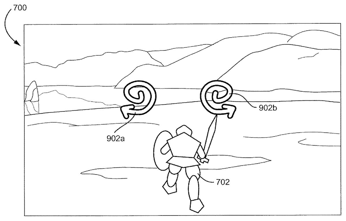
FIG. 4shows an exemplary game environment700with a spell symbol902a,902bimposed thereon. This is one exemplary illustrative non-limiting implementation of a game world where a character702still interacts with the world while the player casts a spell. Symbols902a,902bare imposed over the displayed world, so that the player can keep track of what is transpiring in the game while the spell is cast. Alternatively, the game could be paused while the spell is cast. As another example, the player could be taken to an alternate screen, where he or she could not see the game world, but game time would still continue. Other gameflow control methods during casting are also contemplated.
A single symbol or set of symbols902a,902bmay be displayed, or an entire sequence of symbols may be displayed. The player holding one or more handheld controllers needs to perform the patterns shown on the screen with the respective controller(s). In this example, the player would trace a clock-wise spiral with a left-hand controller and a counter-clockwise spiral with a right-hand controller. As the player is waving one or more controllers around and attempting the gestures, the player is able to better suspend reality and imagine that he or she is actually creating the spell through the gesturing.
FIG. 5shows a player following a set of exemplary instructions displayed on a game screen. In this exemplary implementation, two instruction symbols (vertical arrows)1002,1004are displayed on a screen. The player, in accordance with the symbols1002,1004, moves two controllers from positions1006a,1008ato1006b,1008brespectively. Thus, instead of simply moving a thumb or a finger to indicate a spell (i.e. pressing a button or moving a joystick), the player has actually gestured with his or her hands.
The instructions, additionally, are not limited to symmetrical or straight-line gestures, but rather can be as simple or as complicated as a game designer desires. Further, the instructions need not be made for both hands, they can indicate a single hand, alternate between hands, or always be performed with a single controller.
In the example, once a spell has been selected, the player casts it by moving the controller(s) according to the on-screen prompts. Gestures may be detected using directional accelerometer input.
According to the exemplary game, gestures are shapes which the player performs by moving one or both controllers. These gestures can also be mirrored to add more variety—for example, the player may be required to perform spirals in opposite directions using both controllers at the same time.
Spell casting requires the player to string together a short sequence of one or more gestures. Each spell may have its own unique sequence which is used every time the spell is cast, allowing players to learn spells as they play through the game. The more powerful the spell, the more complex the gesture sequence associated with it may be.
Spell gestures are performed using a timed pattern matching mechanic. On screen HUD prompts indicate to the player which gesture(s) needs to be performed. Points of light may move along each gesture icon while it is displayed, to indicate which direction the player is to move a controller.
Players may have a limited amount of time to perform each gesture in the sequence. If they fail to complete a gesture before its time runs out, or if they perform the gesture incorrectly, it will compromise the spell strength. The gesture sequence may continue though—casting may not stop or restart if a mistake is made.
Successfully performing a gesture causes its icon to highlight blue and a “good” gesture sound effect to play before the next gesture appears on screen. A failed gesture causes the icon to fade down to grey accompanied by a “bad” gesture sound.
When a player finishes a gesture sequence, the picture formed by the spell's gesture sequence may flash up on screen. Additionally, each of the gestures that form the picture may be highlighted or grayed out, depending on whether or not the player performed each corresponding gesture correctly. The more symbols that are highlighted, the stronger the spell effect might be.
FIG. 6shows an exemplary sequence of instructions1102,1104,1106,1108for casting a spell. In this example all four instruction symbols1102,1104,1106,1108require the use of both hands, however, single handed instruction symbols are also possible. Further, in a game with more than one character controlled by more than one player, three or more symbols could be displayed, and each player may have to power some portion of the spell by following the respective instructions associated with that player.
In this exemplary illustrative non-limiting implementation, the vertical motions1102,1106, require identical hand movements, while the horizontal motions1104,1108are mirror images of each other. Additional combinations, such as a vertical movement with one hand and a horizontal movement with the other, may be implemented. Also, the gestures are not limited to straight line movements.
Instruction1102has been blown up to show an initial instruction state1102a, in which the instruction is provided in a first color. Upon success, the instruction changes to a second color1102c. Similarly, failure produces a third color1102b. Methods other than color changing can also be used to indicate success or failure in completing an instruction.
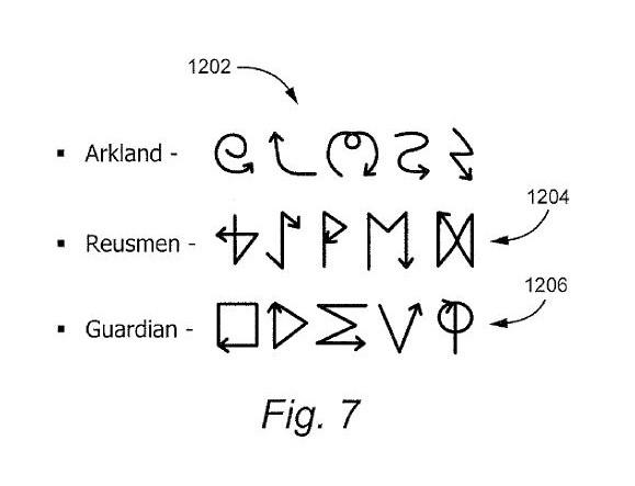
FIG. 7shows three exemplary schools of magic and exemplary symbols associated therewith. In this exemplary illustrative non-limiting implementation, each school has common characteristics among the symbols. The Arkland school1202primarily has swirled wavy symbols. The Reusmen school1204has runic looking symbols. The Guardian school1206consists of mathematical symbols.
In this exemplary implementation, if the player is only provided with access to a single school of magic, the player may more easily become familiar with the movement characteristics of his or her school's magic and may progress more quickly in learning spells. This does not have to be the case, however, a player could have access to all schools, or a game could simply have a series of spells, sharing no intentional relation.
FIG. 8. shows an exemplary spell-casting sequence for casting an exemplary lightning-storm spell. In this exemplary implementation, although this is not necessary, the gestures for the spell themselves form a pictograph of a storm, with swirling cloud gestures followed by lightning bolt gestures. Initially, the player draws the swirling “Ms”1302a,1302bwith both hands. Then the player draws the spirals1304a,1304bwith both hands. This is followed by the upward curves1306a,1306b. Finally, the lightning bolts1308a,1308bare drawn. Through this gesture process, and with the addition of visual and audio effects, the player can feel as though he or she is gathering the forces of nature into clouds and casting down lightning through gesture based movement.
The game may, as each gesture is performed, show some indicia of power gathering around the player, or may show some preliminary spell results as seen inFIGS. 9A and 9B. Also, the controller(s) can begin to vibrate, game animation can change, lightning can begin to crackle, winds howl, etc. All these effects can be designed to more fully draw the player into the game experience. Any or all of the effects can be omitted as well, or additional methods of immersing the player may be used.
According to the exemplary implementation, a visual effect representing the magical energy being drawn upon by the hero appears during casting. This effect builds in intensity to indicate how accurately the player is casting the spell, becoming more visible based on how closely the player is matching the instructions.
The appearance of this magical energy may depend on the hero's faction—for a Reusmen it might be a swarm of ghostly animal spirits swirling around them, for an Arklander a white light surrounding them, for a Malbett a growing black mist rising from the ground.
Additionally (if feasible) the hero might blend between two casting animation loops—one with their head down and their hands kept close to their chest, the other with their head tilted back and arms held aloft. The better the player is doing, the more the hands-in-the-air animation is blended in.
While the hero is casting a spell, a Power bar may gradually drop to show that their magical power is being drained. The amount of Power spent at any point during casting is equal to the total Power cost of the spell multiplied by the percentage of the glyph/gesture sequence that has been completed. As the Power bar falls past a spell icon, the icon fades back to grey to indicate that the spell can no longer be cast.
If the hero cancels the spell before they finish casting it, the Power bar stops falling and no further Power is taken from them. Otherwise the bar continues to fall until the spell is cast.
Additionally, the software may apply more damage to the player character when casting magic.
FIGS. 9A and 9Bshow exemplary results of the spell ofFIG. 8cast with varying degrees of success. InFIGS. 9A and 9B, two different results of the lightning storm spell are shown. In both exemplary illustrative non-limiting implementations, the spell is shown as a gathering storm. In both figures, the first two gestures are successful, resulting in the corresponding pictures1402a,1402band1404a,1404b. Then, however, the player inFIG. 9Acompletes the third gesture correctly, while the player inFIG. 9Bdoes not. Thus, while the cloud1406ahas nearly doubled in size, the cloud1406bhas remained the same. Although both players complete the final gesture correctly, the player fromFIG. 9Ahas a much bigger lightning storm1408athen the player fromFIG. 9B. The player fromFIG. 9Asucceeds in attacking five groups of enemies1410a,1412a, and1414a. The player fromFIG. 9B, however, only strikes three groups of enemies1412b. The enemies of groups1410band1414bremain to give combat.
Actual spell implementations may come in many forms, for example, activating special effects or spawning fantasy units (as seen inFIG. 10).
One exemplary illustrative non-limiting implementation for determining spell power is as follows:
Spell Strength=Accuracy/√(Time Taken/Time Allowed)
In this exemplary implementation, the minimum time taken is capped at half the time allowed, and if the spell was not completed before the timer ran out the time taken is set to be equal to the time allowed.
According to this exemplary implementation, accuracy is the percentage of the gestures in the sequence that were successfully performed. If a gesture required movement of two controllers, failure with respect to either controller is considered a failure of the gesture.
Then, in this exemplary illustrative non-limiting implementation, the spell strength is broken down into four categories:Perfect—Maximum powerExcellent—80% powerFair—50% powerPoor—<50% power
If poor is set as the baseline, then perfect is equivalent to 200% power. Additionally, the numbers shown are for convenience and are not intended to be limiting, any number of tiers and power upgrades/downgrade values may be used. In addition to increasing spell power, spell effects can be improved/downgraded/added. For example, an ice storm which normally does damage only, might freeze foes in place with a perfect cast, allowing the character to get off a number of attacks against the frozen foes. These are all exemplary implementations provided for example purposes only.
FIG. 10shows yet another exemplary game environment700with an exemplary summoning spell having been cast. Here the Hero character602has summoned up a giant elemental1506to trample his foes604. Either the spell was not performed perfectly or it was insufficient to kill all of his enemies, because at least one enemy604aremains unharmed. Of course, the elemental1506may have also simply not gotten around to smashing enemy604ayet.
A vast variety of spells and magical effects can be implemented with the present system, the only limits being the imaginations of game designers. Players can experience a whole new type of spell casting, where they have a much more interactive experience with the game environment. Although many of the examples herein have been shown with respect to a single player game, the system taught hereby can be used in all sorts of games.
Many player vs. player and multi-player implementations of the system are possible, and the disclosure with respect to the single player game given herein is not intended to limit this system to games of that type. Nor is the system limited to the RPG game genre.
Exemplary Video Game Platform
Techniques described herein can be performed on any computer graphics system including a personal computer, a home video game machine, a portable video game machine, a networked server and display, a cellular telephone, a personal digital assistant, or any other type of device or arrangement having computation and graphical display capabilities and outfitted with a motion tracked controller. One exemplary illustrative non-limiting implementation includes a home video game system such as the Nintendo Wii 3D video game system. One exemplary illustrative non-limiting implementation is described below, but other implementations are possible.
FIG. 11shows a non-limiting example game system10including a game console100, a television or other display102and a handheld controller107.
Game console100executes a game program or other application stored on optical disc104or other memory media inserted into slot105formed in housing110thereof. The game program (or other application) execution result is displayed on display102to which game console100is connected by cable106or otherwise. Audio associated with the game program or other application is output via television speakers109. While an optical disk is shown inFIG. 11for use in storing video game software, the game program or other application may alternatively or additionally be stored on other storage media such as semiconductor memories, magneto-optical memories, magnetic memories and the like and/or downloaded over a network or by other means.
An exemplary illustrative non-limiting handheld controller implementation107wirelessly transmits data such as game control (and other) data to the game console100. The game control data may be generated using an operation section of controller107. Controller107may also wirelessly receive data transmitted from game console100. Any one of various wireless protocols such as Bluetooth®, RF, IR or other protocols may be used for the wireless transmissions between controller107and game console100.
Exemplary controller107also includes an imaging information calculation section (FIG. 15) for capturing and processing images from light-emitting devices108aand108bassociated with display102. A center point between light-emitting devices108aand108bmay be aligned with a vertical center line of display102. The images from light-emitting devices108aand108bcan be used to determine a direction in which controller107is pointing as well as a distance of controller107from display102. By way of example without limitation, light-emitting devices108aand108bmay be implemented as two LED modules (hereinafter, referred to as “markers”) provided in the vicinity of a display screen102. The markers each output infrared light. The imaging information calculation section of controller107detects the light output from the LED modules to determine a direction in which controller107is pointing and a distance of controller107from display102. Although markers108aand108bare shown inFIG. 1as being above television100, they may also be positioned below television100or in other configurations.
With reference to the block diagram ofFIG. 12, an exemplary illustrative non-limiting game console100includes a RISC or other central processing unit (CPU)204for executing various types of applications including (but not limited to) video game programs. CPU204executes a boot program stored in a boot ROM (not shown) to initialize game console100, and then executes an application (or applications) stored on optical disc104which is inserted in optical disk drive208. User-accessible eject button210provided on housing110of game console100may be used to eject an optical disk from disk drive208.
In one example implementation, optical disk drive208receives both optical disks of a first type (e.g., of a first size and/or of a first data structure, etc.) containing applications developed for execution by CPU204and graphics processor216and optical disks of a second type (e.g., of a second size and/or a second data structure) containing applications originally developed for execution by a different CPU and/or graphics processor. For example, the optical disks of the second type may be applications originally developed for the Nintendo GameCube platform.
CPU204is connected to system LSI202that includes graphics processing unit (GPU)216with an associated graphics memory220, audio digital signal processor (DSP)218, internal main memory222and input/output (IO) processor224.
IO processor224of system LSI202is connected to one or more USB ports226, one or more standard memory card slots (connectors)228, WiFi or other wireless or other LAN module230, flash memory232and wireless controller module240.
USB ports226are used to connect a wide variety of external devices to game console100. These devices include, by way of example without limitation, game controllers, keyboards, storage devices such as external hard-disk drives, printers, digital cameras, and the like. USB ports226may also be used for wired network (e.g., LAN) connections. In one example implementation, two USB ports226are provided, but other configurations are possible.
Standard memory card slots (connectors)228are adapted to receive industry-standard-type memory cards (e.g., SD memory cards) in one exemplary illustrative non-limiting example. In one example implementation, one memory card slot228is provided. These memory cards are generally used as data carriers. For example, a player may store game data for a particular game on a memory card and bring the memory card to a friend's house to play the game on the friend's game console. The memory cards may also be used to transfer data between the game console and personal computers, digital cameras, and the like. Flash memory232stores, by way of example without limitation, game save data, system files, internal applications for the console and downloaded data (such as games).
WiFi module230enables game console100to be connected to a wireless access point. The access point may provide internet connectivity for on-line gaming with players at other locations (with or without voice chat capabilities), as well as web browsing, e-mail, file downloads (including game downloads) and many other types of on-line activities. In some implementations, WiFi module230may also be used for communication with other game devices such as suitably-equipped hand-held game devices. Module230is referred to herein as “WiFi”, which is generally used in connection with the family of IEEE 802.11 specifications. However, game console100may alternatively or additionally use wireless modules that conform to other wireless or wired standards.
Wireless controller module240receives signals wirelessly transmitted from one or more controllers107and provides these received signals to IO processor224. Any number of separate controllers may be used to provide multi-player inputs. The signals transmitted by controller107to wireless controller module240may include signals generated by controller107itself as well as by other devices that may be connected to controller107. By way of example, some games may utilize separate right- and left-hand inputs. For such games, another controller (not shown) may be connected to controller107and controller107could transmit to wireless controller module240signals generated by it and by the other controller.
Wireless controller module240may also wirelessly transmit signals to controller107. By way of example without limitation, controller107(and/or another game controller connected thereto) may be provided with vibration circuitry and vibration circuitry control signals may be sent via wireless controller module240to control the vibration circuitry. By way of further example without limitation, controller107may be provided with (or be connected to) a speaker (not shown) and audio signals for output from this speaker may be wirelessly communicated to controller107via wireless controller module240. By way of still further example without limitation, controller107may be provided with (or be connected to) a display device (not shown) and display signals for output from this display device may be wirelessly communicated to controller107via wireless controller module240or otherwise.
Proprietary memory card slots246are adapted to receive proprietary memory cards. In one example implementation, two such slots are provided. These proprietary memory cards have some non-standard feature such as a non-standard connector or a non-standard memory architecture. For example, one or more of the memory card slots246may be adapted to receive memory cards developed for the Nintendo GameCube or other platform. In this case, memory cards inserted in such slots can transfer data from games developed for the GameCube or other platform. In an example implementation, memory card slots246may be used for read-only access to the memory cards inserted therein and limitations may be placed on whether data on these memory cards can be copied or transferred to other storage media such as standard memory cards inserted into slots228.
One or more controller connectors244are adapted for wired connection to respective game controllers. In one example implementation, four such connectors are provided for wired connection to game controllers for the Nintendo GameCube platform. Alternatively, connectors244may be connected to respective wireless receivers that receive signals from wireless game controllers. These connectors enable players, among other things, to use controllers for the Nintendo GameCube platform when an optical disk for a game developed for this platform is inserted into optical disk drive208.
A connector248is provided for connecting game console100to DC power derived, for example, from an ordinary wall outlet. Of course, the power may be derived from one or more batteries or by any other desired means.
GPU216performs image processing based on instructions from CPU204. GPU216includes, for example, circuitry for performing calculations and operations for displaying textured and/or shaded three-dimensional (3D) graphics. GPU216performs image processing using graphics memory220(which may be dedicated for image processing) and internal main memory222. GPU216generates image data for output to television102by audio/video connector214via audio/video IC (interface)212. External main memory206and internal main memory222are storage areas directly accessible by CPU204. For example, these memories can store an application program such as a game program read from optical disc104by the CPU204, various types of data or the like.
Audio DSP218performs audio processing based on instructions from CPU204. The audio generated by audio DSP218is output to television102by audio/video connector214via audio/video IC212.
ROM/RTC238includes a real-time clock and preferably runs off of an internal battery (not shown) so as to be usable even if no external power is supplied. ROM/RTC238also may include a boot ROM and SRAM usable by the console.
Power button242is used to power game console100on and off. In one example implementation, power button242is depressed for a specified time (e.g., one or two seconds) to turn the console off so as to reduce the possibility of inadvertent turn-off. Reset button244is used to reset (re-boot) game console100.
With reference toFIGS. 13A, 13B and 14, example controller107includes a housing301on which operating controls302a-302hare provided. Housing301has a generally elongated rectangular shape and is sized to be conveniently holdable in a player's hand. Cross-switch302ais provided at the center of a forward part of a top surface of the housing301. Cross-switch302ais a cross-shaped four-direction push switch which includes operation portions corresponding to the directions designated by the arrows (front, rear, right and left), which are respectively located on cross-shaped projecting portions. A player selects one of the front, rear, right and left directions by pressing one of the operation portions of the cross-switch302a. By actuating cross-switch302a, the player can, for example, move a character in different directions in a virtual game world, control a ball, attack an enemy, etc.Cross-switch302ais described by way of example. Other types of operation sections may be used. By way of example without limitation, a composite switch including a push switch with a ring-shaped four-direction operation section and a center switch may be used. By way of further example without limitation, any or all of the following may be used: an inclinable stick such as a joystick projecting from the top surface of housing301that outputs signals in accordance with the inclining direction of the stick;a horizontally slidable disc-shaped member that outputs signals in accordance with the sliding direction of the disc-shaped member;a touch pad;separate switches corresponding to at least four directions (e.g., front, rear, right and left) that output respective signals when pressed by a player;other.
In one exemplary illustrative non-limiting implementation, buttons (or keys)302bthrough302gare provided rearward of cross-switch302aon the top surface of housing301. Buttons302bthrough302gare operation devices that output respective signals when a player presses them. For example, buttons302bthrough302dare respectively an “X” button, a “Y” button and a “B” button. Buttons302ethrough302gare respectively a select switch, a menu switch and a start switch, for example. Generally, buttons302bthrough302gare assigned various (variable) functions in accordance with the application being executed by game console100. In an exemplary arrangement shown inFIGS. 13A, 13B, buttons302bthrough302dare linearly arranged along a front-to-back centerline of the top surface of housing301. Buttons302ethrough302gare linearly arranged along a left-to-right line between buttons302band302d. Button302fmay be recessed from a top surface of housing701to reduce the possibility of inadvertent depression by a player grasping controller107.
Button302his provided forward of cross-switch302aon the top surface of the housing301. Button302his a power switch for remote on-off switching of the power to game console100. Button302hmay also be recessed from a top surface of housing301to reduce the possibility of inadvertent depression.
In one exemplary illustrative non-limiting implementation, a plurality (e.g., four) of LEDs304is provided rearward of button302con the top surface of housing301. Controller107is assigned a controller type (number) so as to be distinguishable from the other controllers used with game console100in a multiplayer context. LEDs304may be used to provide a player a visual indication of his or her assigned controller number. For example, when controller107transmits signals to wireless controller module240, one of the plurality of LEDs corresponding to the controller type is lit up.
With reference toFIG. 13B, a recessed portion308is formed on a bottom surface of housing301. Recessed portion308is positioned so as to receive an index finger or middle finger of a player holding controller107. A button302iis provided on a rear, sloped surface308aof the recessed portion. Button302ifunctions, for example, as an “A” button which can be used, by way of illustration, as a trigger switch in a shooting or other game.
As shown inFIG. 14, an imaging element305ais provided on a front surface of controller housing301in one exemplary illustrative non-limiting implementation. Imaging element305ais part of an imaging information calculation section of controller107that analyzes image data received from markers108aand108b. Imaging information calculation section305has a maximum sampling period of, for example, about 200 frames/sec., and therefore can trace and analyze even relatively fast motion of controller107. Additional details may be found in application Ser. No. 11/532,328, entitled “VIDEO GAME SYSTEM WITH WIRELESS MODULAR HANDHELD CONTROLLER,” filed on Sep. 15, 2006; Ser. No. 11/445,280, entitled “INFORMATION PROCESSING PROGRAM,” filed on Jun. 2, 2006; and application Ser. No. 11/441,146, entitled “INFORMATION PROCESSING SYSTEM AND PROGRAM THEREFOR,” filed on May 26, 2006. The entire contents of each of these applications are incorporated herein.
Connector303is provided on a rear surface of controller housing301. Connector303is used to connect devices to controller107. For example, a second controller of similar or different configuration may be connected to controller107via connector303in order to allow a player to play games using game control inputs from both hands. Other devices including game controllers for other game consoles, input devices such as keyboards, keypads, touchpads and output devices such as speakers and displays may be connected to controller107using connector303or by other means.
For ease of explanation in what follows, a coordinate system for controller107will be defined. As shown inFIGS. 13A, 13B and 14, a left-handed X, Y, Z coordinate system has been defined for controller107. Of course, this coordinate system is described by way of example without limitation and the systems and methods described herein are equally applicable when other coordinate systems are used.
As shown in the block diagram ofFIG. 15, controller107includes a three-axis, linear acceleration sensor507that detects linear acceleration in three directions, i.e., the up/down direction (Z-axis shown inFIGS. 3A, 3B and 4), the left/right direction (X-axis shown inFIGS. 3A, 3B and 4), and the forward/backward direction (Y-axis shown inFIGS. 3A, 3B and 4). Alternatively, a two-axis linear accelerometer that detects only linear acceleration along each of the Y-axis and Z-axis may be used or a one-axis linear accelerometer that detects only linear acceleration along the Z-axis may be used. Generally speaking, the accelerometer arrangement (e.g., three-axis or two-axis) will depend on the type of control signals desired. As a non-limiting example, the three-axis or two-axis linear accelerometer may be of a type available from Analog Devices, Inc. (ADXL303) or STMicroelectronics N.V. Preferably, acceleration sensor507is an electrostatic capacitance or capacitance-coupling type that is based on silicon micro-machined MEMS (micro-electromechanical systems) technology. However, any other suitable accelerometer technology (e.g., piezoelectric type or piezoresistance type) now existing or later developed may be used to provide three-axis or two-axis linear acceleration sensor507.
As one skilled in the art understands, linear accelerometers as used in acceleration sensor507are capable of detecting acceleration along a straight line corresponding to each axis of the acceleration sensor. In other words, the direct output of acceleration sensor507is limited to signals indicative of linear acceleration (static or dynamic) along each of the two or three axes thereof. As a result, acceleration sensor507in one exemplary illustrative non-limiting implementation cannot directly detect movement along a non-linear (e.g. arcuate) path, rotation, rotational movement, angular displacement, tilt, position, attitude or any other physical characteristic.
However, through additional processing of the linear acceleration signals output from acceleration sensor507, additional information relating to controller107can be inferred or calculated (i.e., determined), as one skilled in the art will readily understand from the description herein. For example, by detecting static, linear acceleration (i.e., gravity), the linear acceleration output of acceleration sensor507can be used to determine tilt of controller107relative to the gravity vector by correlating tilt angles with detected linear acceleration. In this way, acceleration sensor507can be used in combination with micro-computer502of controller107(or another processor) to determine tilt, attitude or position of controller107. Similarly, various movements and/or positions of controller107can be calculated through processing of the linear acceleration signals generated by acceleration sensor507when controller107containing acceleration sensor307is subjected to dynamic accelerations by, for example, the hand of a user.
In other exemplary illustrative non-limiting implementations, acceleration sensor507may include an embedded signal processor or other type of dedicated processor for performing any desired processing of the acceleration signals output from the accelerometers therein prior to outputting signals to micro-computer502. For example, the embedded or dedicated processor could convert the detected acceleration signal to a corresponding tilt angle (or other desired parameter) when the acceleration sensor is intended to detect static acceleration (i.e., gravity). Controllers not equipped with motion sensing technology can also be used with the exemplary illustrative non-limiting implementations.
FIG. 15shows image information calculation section505of controller107as including infrared filter528, lens529, imaging element305aand image processing circuit530. Infrared filter528allows only infrared light to pass therethrough from the light that is incident on the front surface of controller107. Lens529collects and focuses the infrared light from infrared filter528on imaging element305a. Imaging element305ais a solid-state imaging device such as, for example, a CMOS sensor or a CCD. Imaging element305acaptures images of the infrared light from markers108aand108bcollected by lens309. Accordingly, imaging element305acaptures images of only the infrared light that has passed through infrared filter528and generates image data based thereon. This image data is processed by image processing circuit520which detects an area thereof having high brightness, and, based on this detecting, outputs processing result data representing the detected coordinate position and size of the area to communication section506. From this information, the direction in which controller107is pointing and the distance of controller107from display101can be determined. Controllers not equipped with light detecting technology can also be used with the exemplary illustrative non-limiting implementations.
Vibration circuit512may also be included in controller107. Vibration circuit512may be, for example, a vibration motor or a solenoid. Controller107is vibrated by actuation of the vibration circuit512(e.g., in response to signals from game console100), and the vibration is conveyed to the hand of the player holding controller107. Thus, a so-called vibration-responsive game may be realized.
As described above, acceleration sensor507detects and outputs the acceleration in the form of components of three axial directions of controller107, i.e., the components of the up-down direction (Z-axis direction), the left-right direction (X-axis direction), and the front-rear direction (the Y-axis direction) of controller107. Data representing the acceleration as the components of the three axial directions detected by acceleration sensor507is output to communication section506. Based on the acceleration data which is output from acceleration sensor507, motion of controller107can be determined.
In one exemplary illustrative non-limiting implementation, communication section506includes micro-computer502, memory503, wireless module504and antenna505. Micro-computer502controls wireless module504for transmitting and receiving data while using memory503as a storage area during processing. Micro-computer502is supplied with data including operation signals (e.g., cross-switch, button or key data) from operation section302, acceleration signals in the three axial directions (X-axis, Y-axis and Z-axis direction acceleration data) from acceleration sensor507, and processing result data from imaging information calculation section505. Micro-computer502temporarily stores the data supplied thereto in memory503as transmission data for transmission to game console100. The wireless transmission from communication section506to game console100is performed at a predetermined time interval. Because game processing is generally performed rapidly at for example a cycle of 1/60 sec. (16.7 ms), the wireless transmission is preferably performed at a cycle of a shorter time period. For example, a communication section structured using Bluetooth® technology can have a cycle of 5 ms. At transmission time, micro-computer502outputs the transmission data stored in memory503as a series of operation information to wireless module504.
Wireless module504uses, for example, Bluetooth® technology to send the operation information from antenna505as a carrier wave signal having a specified frequency. Thus, operation signal data from operation section302, the X-axis, Y-axis and Z-axis direction acceleration data from acceleration sensor507, and the processing result data from imaging information calculation section505are transmitted from controller107. Game console100receives the carrier wave signal and demodulates or decodes the carrier wave signal to obtain the operation information (e.g., the operation signal data, the X-axis, Y-axis and Z-axis direction acceleration data, and the processing result data). Based on this received data and the application currently being executed, CPU204of game console100performs application processing. If communication section506is structured using Bluetooth® technology, controller107can also receive data wirelessly transmitted thereto from devices including game console100. Controllers107connected to a game console or other device by a wire or other means may also be used with the exemplary illustrative non-limiting implementations.
The exemplary illustrative non-limiting system described above can be used to execute software stored on optical disk104or in other memory that controls it to implement a video game having a magic system. Also, while a controller provided with motion sensing elements is used in the above example, a system where an external element sensed controller motion could also be used. Exemplary illustrative non-limiting software controlled techniques for implementing such a game will now be described.
Exemplary Illustrative Game Program Flow
InFIG. 16, an exemplary illustrative nonlimiting flow for a magic invoking system is shown. According to this exemplary implementation, the player actually activates a magic mode before spell selection is performed (1602). This could involve pressing of a button, a gesture with a controller, a series of commands, etc. Once the player has activated the magic mode (1602), the player then selects a desired spell (1604). Again, spell selection can be implemented in various ways. For example, in this illustrative embodiment, while game time slows in magic mode, it does not cease entirely and events continue to transpire around the game character. Thus, if a developer wished to allow the character to retain control over motion, then a directional pad on the controller might be used to move the character while in magic mode, and a movement of the motion sensing controller might cause spell selection. Alternatively, time could stop entirely while the player selects a particular spell (1604).
Once a spell has been selected (1604) the game software then causes one or more instructions to be displayed on a display (1606). According to this implementation, if there is more than one instruction, the game software displays the instructions one at a time. It would also be possible to display the entire instruction set at once, or display a current instruction and a next instruction, etc.
According to this exemplary implementation, once the first instruction has been displayed, the game software detects player input (1608). Player input consists of moving the motion sensing controller in a pattern resembling the symbol shown on the screen. In this exemplary implementation the symbol also has an arrow included, so the player knows in which direction to proceed. For example, if a circle is shown, the arrow helps the player in determining whether it is a clockwise circle or a counter-clockwise circle. The process of displaying an instruction symbol (1606) and detecting a player gesture pattern (1608) continues until all symbols for a particular spell have been attempted.
Once the player has attempted each instruction, the game can then create the spell effect (1610). According to this exemplary implementation, the spell effect power or result is affected by the number of player successes and failures on correctly gesturing in accordance with the displayed instruction symbols. A developer, however, may choose not to take these factors into account, or may select other suitable factors to affect the spell outcome. Additionally, while in this exemplary embodiment the spell continues whether or not a player succeeded with each gesture, the spell could also be stopped the moment a player fails to complete a successful gesture.
Some facets a developer may wish to consider include, but are not limited to:activation of magic spellsselection of spellthe casting mechanismspell activation, including a consideration of spell qualitytargeting of any spells that require a positional component
FIG. 17shows another exemplary magic invoking system flow according to one exemplary illustrative non-limiting implementation. Again, according to this implementation, the player first enters a magic mode (1702). While the player is said to have “entered” a magic mode, in essence this simply results in allowing spell selection and casting. Since motion based control may be used for another feature of the game, such as swinging a sword, the game may need to distinguish between a magic gesture and a sword gesture, hence the magic mode. Other options are available, however. For example, in a game provided with two motion based controllers, one held in each hand, a left hand controller could be used for spell gestures and a right hand controller for sword gestures, allowing a character to fight and cast simultaneously.
After entering magic mode, the player selects a desired spell (1704). In this implementation, the system checks to see if there is enough power for the desired spell (1706), but the system could also simply prohibit selection of spell for which the player had insufficient power.
Once the desired spell is selected (1706), the game software displays a first spell instruction on a display (1708). The player then attempts to match the symbol shown on the screen with a gesture from the motion sensing controller. By gesturing with the controller, the player can feel as if they are summoning up the elemental forces necessary to complete the spell, immersing themselves in the game. Again, although the controller is referred to as a motion sensing controller, a device independent of the controller that detects the controllers motion would also be sufficient.
After the player has attempted an input, the game software checks to see if the input is correct (1710). In this exemplary implementation, the game software checks after a player stops moving a controller or after a time limit expires. The software could, however, provide a constant check, so that if any point the player's input strayed too far afield, the software could register a failed input (1712). In this exemplary implementation, if the input is incorrect after it has been attempted, or if the player did not complete the symbol in a requisite time period, the game software indicates a failed input (1712).
If, however, the player was successful in the input attempt, then the game software indicates a player success (1716). Indicia of success or failure can take a variety of forms. The symbol could turn a different color for each, a sound could play for each, there may only be a change in the symbol for a success or maybe only for a failure, the player could perform a different animation, the controller could tremble, etc. Alternatively, no indication of success or failure may be given at all.
After success or failure has been determined (1714), the game then subtracts an appropriate amount of magic power (1718). In this exemplary implementation, as each gesture is completed, some magic is depleted from the character's store (1718). Also, in this exemplary implementation, the player has the option to quit attempting the spell at any point. If the player does so, then the magic already spent is forfeit. Alternatively, a fizzling version of the spell may be cast, or some other effect may occur.
Once the magic is subtracted, the game checks to see if there are any instructions remaining in the sequence (1720). If there are instructions remaining, the game checks to see if the player has elected to abort the sequence (1722), before proceeding to display the next instruction (1708). If the player has elected to abort magic mode, then the process exits (1726) and the spent magic is forfeit.
If, however, there are no steps remaining, then, according to this exemplary implementation, the game determines how the spell is to be altered based on cast speed and accuracy of gestures. For example, the spell may be given more damage power, a lightning storm may be given more bolts, a hurricane may last longer, a monster may be bigger, etc. Spells can also have a base point which may be downgraded if a spell was performed particularly horribly. Comedic effects can also be included here, such as a spell to summon a dragon might produce a gecko if the player failed on every gesture attempt.
Finally, before the spell is actually displayed (1732), the game software determines if there is any additional input, such as targeting a spell, needed (1728). If a player is facing a vast field of foes, then it may be necessary for the player to select some portion of the enemy to be the recipient of the spell, and it may not be desirable to have this portion randomly selected. If any additional input is needed, the game software prompts the player and gathers the input (1730) and then the spell effect is displayed in the game.
While a specific algorithm for spell processing has been described with respect toFIG. 17, it is for exemplary purposes only, and any suitable method may be used.
Another exemplary illustrative non-limiting implementation is shown in the state diagram ofFIG. 18. Initially, a player activates a magic mode, or makes some indication that spell-casting is to begin (1802). The player then, in this exemplary implementation, is provided with the option to select a spell (1804). As long as the player does not select a spell, the program waits for a spell to be selected. Once a spell is selected, the first gesture for that spell is displayed (1808).
While the spell gesture is being displayed (1808), there will likely be at least a point where the spell gesture is shown but not completed. Since, in this exemplary implementation, there is a time limit, the program will check while the gesture is not completed to ensure the time limit has not expired (1806). If the time limit expires before the gesture is completed, the program registers the gesture as failed and subtracts some portion of magic power (1812).
If the gesture is completed before the time limit is expired, the program then checks for a success or failure (1810). Upon failure, the program subtracts some power and registers a failure (1812). Upon success, the program subtracts some power and registers a success (1814). In either event, the program then checks to see if any gestures are remaining to be performed (1816). If so, the program returns to the gesture display state (1808), otherwise, the selected spell effect is generated (1818).
Again, this state diagram is shown as an exemplary state diagram for explanatory purposes only and is not intended to limit the scope of the invention in any way.
Exemplary Game Sample Code (for illustrative Exemplary Purposes Only)
Included below is exemplary illustrative non-limiting code examples for various aspects of the game provided as a non-limiting example herethroughout:3 main modules could be considered for implementation:—1) an action component that integrates the magic system with other systems2) a magic system manager that handles all player interaction.3) a HUD component that updates according to the state of the magic system—this will be a HUD overlay4) Spell classes that would describe different characteristic behaviour of each spell. For example, gesture sequences, time allowed Impact range and strength etc.
Spell classes may also be useful. The responsibility for any specific behaviour dictates that most of this functionality should be contained within the individual spell classes. The spells themselves could be designer editable and as such could have reflected base-classes and instances.
The exemplary magic system could be based on 4 main modules, namely1. cPlayerActionMagic2. cMagicSystemManager3. cSpell4. cHudMagicOverlay
cPlayerActionMagic will be responsible to activate the magic mode and shift player control to the cMagicSystemManager. The magic system module will then process input and update states as well as keep track of the available spells. This information can then be used by the Hud component for displaying appropriate icons on the screen. After the magic system module has finished processing all of the states the magic action will be popped off from the current players stack of actions and control will resume to normal mode.
cPlayerActionMagic
An action class could to be put in place which will inherit from a cAction.h base class. The purpose of this class would be to shift the player control to the magic system and let it handle all the user interaction. Magic system manager can be invoked through this class to handle different states (discussed below) of magic spell.
This class could be instantiated from other action modules currently at the top of the action stack.
The main interface to this class would be:
UpdateAction( )
This is a pure virtual function and could be implemented by all the player actions. It would return an eUpdateAction value which will signal the activation or deactivation of the magic mode in the game. UpdateAction would record input from a cPlayerControl class and pass it on to a Magic system module for further processing.
cMagicSystemManager
The magic system could store internal state so that the response to player input will be contextual during its update. Likely states will be:
SELECTING_SPELLCAST_MODEACTIVATING_SPELLTARGETTING_SPELLENDING_SPELL
It may also store details of the current spell selected, as well as spell availability. There may also be spell classes that will be reflected classes that may be “owned” by hero classes. The magic system will likely need to know about the spells owned by the current player. Any interaction with the spell data or current player status would be facilitated by the Action module.
This could be a singleton class which will be responsible to manage states of the magic system. It may be invoked from cPlayerActionMagic. Following is the main data and behavior that may be implemented by this class:
[DATA]enum eMagicState{SELECT_SPELL,CAST_SPELL,ACTIVATING_SPELL,TARGETING_SPELL,ENDING_SPELL};enum eMagicMode{MAGIC_CONTINUE,MAGIC_END};emSpellIndex; //this will keep track of currently selected spell.emGesturelevel; //this will keep track of next gesture in gesture sequencemGestureSequence; // will hold the sequence entered by the user tobe matched with the intended //sequence from spell objectcSprite *mSpellIcons[NUMOFALLSPELLS]; //pointer to icon graphicdata for all the spellscSprite*mGestureIcons[NUMOFGESTURES]; //pointer to all the gestures[INTERFACE]Update( )Getgestures( )GetAvailableSpells( );[UTILITIES]getgesturefromSpell( )getspellsFromSpell( )UpdateSelect( )UpdateCast( )UpdateActivate( )UpdateTarget( )UpdateEnd( )IsSelected( )
Based on the current state, the magic system module may process input and update the pointer to graphic data which then can be used by the Hud component to display icons and prompts on the screen.
CHudMagicOverlay
This Hud component may query the manager class on each update for the graphic icon to be displayed on the screen. cHudMagicOverlay would inherit from cHuditems and may implement the virtual interface update ( ) and draw( ). These may in turn invoke update and draw methods of corresponding current magic system state. No player control would be handled in the Hud component.
[INTERFACE]Update( )Draw ( )[UTILITIES]UpdateSelect( )UpdateCast ( )UpdateActivate ( )...DrawSelect( )DrawCast( )...cSpell
This class may hold all of the spell data and reflect it in order to be tuned and modified by the designer. The class may be queried and updated by magic module and unit module both. Therefore it might implement some helper functionality.
[DATA]ImpactstrengthTotalGesturesTimetoCompleteGestures[TotalGestures]Gesturetime[TotalGestures][INTERFACE]IsEnoughMana( )UpdateMana( )CalculateQuality( )[UTILITIES]
While the technology herein has been described in connection with exemplary illustrative non-limiting implementations, the invention is not to be limited by the disclosure. The invention is intended to be defined by the claims and to cover all corresponding and equivalent arrangements whether or not specifically disclosed herein.
Claims
- A method of tracing symbols using a handheld input device wirelessly coupled to a computer-based system comprising a processor, memory and a display interface connected to a display device, the handheld input device including a sensor that can sense spatial controller pointing and/or motion in free space, the method comprising: displaying, on the display device, a symbol comprising a sequence of cursively-connected line segments and/or arcs;instructing a user to trace the displayed sequence of cursively-connected line segments and/or arcs comprising the symbol by moving the handheld input device in free space;detecting, with the processor, at least spatial input device pointing and/or motion by monitoring signals sensed by the sensor and provided by the handheld input device to the computer-based system;determining, with the processor, in response to monitoring the signals, whether the user moves the handheld input device in free space to gesture the displayed sequence of cursively-connected line segments and/or arcs;and varying a degree of effectiveness of a game action based on the gesturing of the displayed sequence of cursively-connected line segments and/or arcs that is determined based on the user's movement of the handheld input device in free space, the game action using a parameter corresponding to a strength defined by, at least, an accuracy of tracing the sequence divided by a value produced based on a quotient derived from a time taken for completing the tracing of the sequence of cursively-connected line segments and/or arcs and a time allowed for completing the tracing of the sequence of cursively-connected line segments and/or arcs.
- The method of claim 1 , wherein two handheld input devices are spatially moved to provide input, each handheld input device being held in a different hand.
- The method of claim 1 , further comprising providing feedback if the user moves the handheld input device to gesture the displayed sequence of cursively-connected line segments and/or arcs.
- The method of claim 1 , wherein the game action is displayed on the display device.
- The method of claim 1 , wherein the handheld input device transmits the signal to the computer-based system.
- The method of claim 1 , wherein the degree of effectiveness is greater when the accuracy of tracing the sequence of cursively-connected line segments and/or arcs is greater.
- A method of instructing player input to a video game controller capable of detecting spatial controller pointing and/or motion along a plurality of axes, comprising: displaying a sequential series of cursively-connected line segments and/or arcs on a display, the cursively-connected line segments and/or arcs defining a pattern in which a player is to spatially trace, in free space, using at least one handheld controller containing an inertial sensor;detecting, with a processor remote from the handheld controller, aspects of the spatial pointing and/or motion of the handheld controller in response to signals the inertial sensor senses and which the handheld controller transmits to the processor;determining, for the cursively-connected line segments and/or arcs in the sequential series, whether or not the detected aspects of the spatial pointing and/or motion of the handheld controller in free space was gestured in an instructed direction;and varying a degree of effectiveness of a game action based on the gesturing of the displayed sequence of cursively-connected line segments and/or arcs that is determined based on the detected aspects of the spatial pointing and/or motion of the handheld controller in free space, the game action using a parameter corresponding to a strength defined by, at least, an accuracy of tracing the sequence divided by a value produced based on a quotient derived from a time taken for completing the tracing of the sequence of cursively-connected line segments and/or arcs and a time allowed for completing the tracing of the sequence of cursively-connected line segments and/or arcs.
- The method of claim 7 , wherein the displaying further includes displaying a sequential series of instructions on a display, the instructions each defining two patterns in which the player is to simultaneously spatially move two handheld controllers using separate hands.
- The method of claim 7 , further including displaying, in conjunction with the displayed pattern, at least one visual indicia that indicates in which direction the at least one handheld controller is to be moved.
- The method of claim 9 , wherein the visual indicia include moving light points that move along the displayed pattern.
- In a system including a processor coupled to a memory and a display, the processor executing software to display information on the display, the processor in wireless communication with a sensor that moves with a user's body part in free space, a method for interacting with an interactive media system to instruct a user how to perform a task, the method comprising: graphically displaying, on the display, at least one choreographic pattern comprising a sequential series of cursively-connected line segments and/or arcs to prompt a user to attempt to mimic said displayed choreographic pattern by tracing in free space;sensing pointing and/or motion with the sensor that moves with a user's body part in free space;detecting, with the processor, whether said sensor has sensed a pointing and/or motion signal having a timing that could correspond to the displayed choreographic pattern;determining, with the processor, in response to the sensor sensing the signal, whether the user moves the sensor in free space to gesture the displayed at least one choreographic pattern;and varying a degree of effectiveness of a game action based on the gesturing of the displayed sequence of cursively-connected line segments and/or arcs that is determined based on the user's movement of the sensor in free space, the game action using a parameter corresponding to a strength defined by, at least, an accuracy of tracing the sequence divided by a value produced based on a quotient derived from a time taken for completing the tracing of the sequence of cursively-connected line segments and/or arcs and a time allowed for completing the tracing of the sequence of cursively-connected line segments and/or arcs.
- The method of claim 11 , wherein said graphically displaying comprises graphically displaying a sequence of choreographic patterns to prompt the user to attempt to mimic each displayed graphical pattern in said sequence by tracing each displayed graphical pattern in free space.
- The method of claim 11 , wherein said sensing includes sensing free space motion of at least one handheld input device.
- The method of claim 11 , wherein said sensing comprises simultaneously sensing instantaneous positions of a left-handed handheld input device and a right-handed handheld input device.
- A system for teaching a user how to form a symbol, comprising: a computer readable storage medium storing a game program;a processor device operable to execute the game program;and at least one handheld controller in communication with the processor device, the handheld controller including an inertial sensor that can sense aspects of pointing and/or motion of a user operating the handheld controller in free space, wherein execution of the game program by the processor device causes at least one instruction comprising a sequential series of cursively-connected line segments and/or arcs to be displayed on a display connected to the processor device, wherein the at least one instruction instructs a player to move the controller in free space to trace the displayed sequential series of cursively-connected line segments and/or arcs, wherein the game program determines, via the processor device, whether the user moves the handheld controller in free space to gesture the displayed sequential series of cursively-connected line segments and/or arcs and varies a degree of effectiveness of a game action based on the gesturing of the displayed sequential series of cursively-connected line segments and/or arcs that is determined based on the user's movement of the handheld input device in free space, the game action using a parameter corresponding to a strength defined by, at least, an accuracy of tracing the sequence divided by a value produced based on a quotient derived from a time taken for completing the tracing of the sequence of cursively-connected line segments and/or arcs and a time allowed for completing the tracing of the sequence of cursively-connected line segments and/or arcs.
- The system of claim 15 , wherein a plurality of instructions are displayed, the instructions comprising displayed symbols.
Disclaimer: Data collected from the USPTO and may be malformed, incomplete, and/or otherwise inaccurate.