U.S. Pat. No. 9,545,567
APPARATUS AND METHOD FOR MANIPULATING A VIRTUAL WORLD BY UTILIZING BIOMETRIC INFORMATION
AssigneeSamsung Electronics Co Ltd
Issue DateMarch 29, 2013
Illustrative Figure
Abstract
An apparatus and method for processing a virtual world. According to certain embodiments of the present disclosure, real-world biometric information on the user may be collected using a bio sensor, and the collected information may be controlled based on the sensor characteristics of the bio sensor, thereby enabling interaction between the real world and the virtual world, as well as between virtual worlds. In addition, an interactive game which is executed in the virtual world on the basis of the collected biometric information may be controlled to thereby produce a virtual world having enhanced realism. Moreover, the real-world health status of a user may be determined and displayed on the basis of the collected biometric information, thereby enabling the health status of the user to be seen.
Description
DETAILED DESCRIPTION Reference will now be made in detail to example embodiments, examples of which are illustrated in the accompanying drawings, wherein like reference numerals refer to the like elements throughout. Example embodiments are described below in order to explain example embodiments by referring to the figures. FIG. 1illustrates an operation of controlling a virtual world object of a virtual world using a sensor in a real world, according to example embodiments. Referring toFIG. 1, a user110in a real world may manipulate an object120of the virtual world using a sensor100in the real world. The user110may input information relating to his or her motion, state, intention, shape, and the like, through the sensor100. The sensor100may transmit control information (CI) related to the motion, state, intention, shape, and the like, of the user110, the CI included in a sensor signal, to a virtual world processing apparatus. In this instance, for example, the virtual world may be classified into a virtual environment and a virtual world object. In addition, the virtual world object may be classified into an avatar and a virtual object. Depending on embodiments, the user110in the real world may include humans, animals, plants, inanimate objects, such as, articles, and even surrounding environment of the user110; however, the present disclosure is not limited thereto. FIG. 2illustrates a bio sensor and sensed information collected by the bio sensor, according to example embodiments. Referring toFIG. 2, a virtual world processing apparatus may use bio sensors111,112,113,114, and115to collect information121,122,123,124,125,126,127,128,129,130,131,132,133, and134about biometrics of a user101, the user101being in a real world. The bio sensors, for example, bio sensors111through115, may collect information about biometrics of the user101in the real world. The bio sensors may include at least one of a body height sensor, a body weight sensor111, a body temperature sensor112, a body fat sensor, a ...
DETAILED DESCRIPTION
Reference will now be made in detail to example embodiments, examples of which are illustrated in the accompanying drawings, wherein like reference numerals refer to the like elements throughout. Example embodiments are described below in order to explain example embodiments by referring to the figures.
FIG. 1illustrates an operation of controlling a virtual world object of a virtual world using a sensor in a real world, according to example embodiments.
Referring toFIG. 1, a user110in a real world may manipulate an object120of the virtual world using a sensor100in the real world. The user110may input information relating to his or her motion, state, intention, shape, and the like, through the sensor100. The sensor100may transmit control information (CI) related to the motion, state, intention, shape, and the like, of the user110, the CI included in a sensor signal, to a virtual world processing apparatus.
In this instance, for example, the virtual world may be classified into a virtual environment and a virtual world object. In addition, the virtual world object may be classified into an avatar and a virtual object.
Depending on embodiments, the user110in the real world may include humans, animals, plants, inanimate objects, such as, articles, and even surrounding environment of the user110; however, the present disclosure is not limited thereto.
FIG. 2illustrates a bio sensor and sensed information collected by the bio sensor, according to example embodiments.
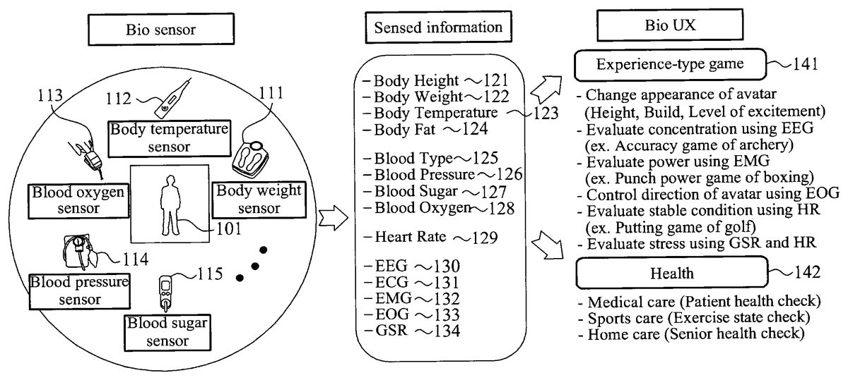
Referring toFIG. 2, a virtual world processing apparatus may use bio sensors111,112,113,114, and115to collect information121,122,123,124,125,126,127,128,129,130,131,132,133, and134about biometrics of a user101, the user101being in a real world.
The bio sensors, for example, bio sensors111through115, may collect information about biometrics of the user101in the real world. The bio sensors may include at least one of a body height sensor, a body weight sensor111, a body temperature sensor112, a body fat sensor, a blood type sensor, a blood pressure sensor114, a blood sugar sensor115, a blood oxygen sensor113, a heart rate sensor, an electroencephalography (EEG) sensor, an electrocardiography (ECG) sensor, an electromyography (EMG) sensor, an electrooculography (EOG) sensor, a galvanic skin reflex (GSR) sensor, a bio sensor, and an electrograph sensor. The sensors listed above are exemplary, and thus, the present disclosure is not limited thereto.
The electrograph sensor may include at least one of the EEG sensor, the ECG sensor, the EMG sensor, the EOG sensor, and the GSR sensor.
The body height sensor may measure a body height121of the user101in the real world. The body weight sensor111may measure a body weight122of the user101in the real world. The body temperature sensor112may measure a body temperature123of the user101in the real world. The body fat sensor may measure a body fat124of the user101in the real world. The blood type sensor may measure a blood type125of the user101in the real world. The blood pressure sensor114may measure a blood pressure126of the user101in the real world. The blood sugar sensor115may measure an amount of glucose present in a blood of the user101in the real world, that is, a blood sugar127. The blood oxygen sensor113may measure an amount of oxygen in the blood of the user101in the real world, that is, a blood oxygen128. The heart rate sensor may measure a heart rate129of the user101in the real world. The EEG sensor may measure an EEG130of the user101in the real world. The ECG sensor may measure an ECG131of the user101in the real world. The EMG sensor may measure an EMG132of the user101in the real world. The EOG sensor may measure an EOG133of the user101in the real world. The GSR sensor may measure a GSR134of the user101in the real world. The electrograph sensor may measure an electrograph between a reference electrode and an active electrode. The sensors, and corresponding sensed information, listed above are exemplary, and thus, the present disclosure is not limited thereto.
The bio sensor may correspond to a sensor configured using a combination of at least two of the body height sensor, the body weight sensor111, the body temperature sensor112, the body fat sensor, the blood type sensor, the blood pressure sensor114, the blood sugar sensor115, the blood oxygen sensor113, the heart rate sensor, the EEG sensor, the ECG sensor, the EMG sensor, the EOG sensor, the GSR sensor, and the electrograph sensor.
The virtual world processing apparatus may adapt the information collected with respect to the biometrics of the user101in the real world, based on capability of the bio sensor. In addition, the virtual world processing apparatus may control a bio user experience (Bio-UX) virtual world to which biometric information of the user101in the real world is to be applied, based on the adapted information.
According to example embodiments, the virtual world processing apparatus may control an experience-type game141that may be played in a virtual world, based on the adapted information.
For example, the virtual world processing apparatus may collect body weight information of the user101in the real world, using the body weight sensor111, and may change an appearance of an avatar in the experience-type game141, based on the collected body weight information.
The virtual world processing apparatus may collect EEG information of the user101in the real world, using the EEG sensor, and may adapt an ability with respect to a concentration in the experience-type game141, for example, an archery game, based on the collected EEG information.
The virtual world processing apparatus may collect EMG information of the user101in the real world, using the EMG sensor, and may adapt an ability with respect to a power in the experience-type game141, for example, an boxing game, based on the collected EMG information.
The virtual world processing apparatus may collect EOG information of the user101in the real world, using the EOG sensor, and may control a direction of an avatar in the experience-type game141based on the collected EOG information.
The virtual world processing apparatus may collect heart rate information of the user101in the real world, using the heart rate sensor, and may adapt an ability with respect to a stable condition in the experience-type game141, for example, a golf game, based on the collected heart rate information.
According to example embodiments, the virtual world processing apparatus may collect a plurality of pieces of biometric information, using a plurality of bio sensors, and may control the experience-type game141, based on the plurality of pieces of biometric information collected or sensed by the bio sensors.
For example, the virtual world processing apparatus may collect GSR information of the user101in the real world, using the GSR sensor, and may collect heart rate information of the user101using the heart rate sensor. Here, the GSR information may correspond to, for example, an emotional change of the user101. The virtual world processing apparatus may adapt an ability with respect to a stress in the experience-type game141, based on the collected GSR information and heart rate information.
According to example embodiments, the virtual world processing apparatus may determine a health142of the user101in the real world, based on adapted information.
For example, the virtual world processing apparatus may collect electrograph information between a reference electrode and an active electrode of the user101, using the electrograph sensor, and may determine the health142of the user101in the real world, based on the collected electrograph information.
Accordingly, the virtual world processing apparatus may check a health of a patient, an exercise state, or a health of a senior, based on adapted information.
FIG. 3illustrates a configuration of a virtual world processing apparatus300, according to example embodiments.
Referring toFIG. 3, a virtual world processing apparatus300that enables interoperability between a virtual world and a real world, or interoperability between virtual worlds may include at least an input unit310and an adapting unit320.
The input unit310may receive an input of sensed information302collected by a bio sensor301with respect to biometrics of a user in the real world. The sensed information302will be described in detail later.
According to example embodiments, the input unit310may receive an input of a plurality of sensed information302from a plurality of bio sensors301.
According to example embodiments, the input unit310may receive an input of virtual (VR) object metadata361indicating information with respect to a virtual object360in the virtual world. In addition, the input unit310may receive an input of a sensor adaptation preference metadata352for controlling the sensed information302. The sensor adaptation preference352will be described in detail later.
The adapting unit320may adapt the sensed information302, based on sensor capability metadata303associated with a capability of the bio sensor301. The sensor capability metadata303will be described in detail later.
For example, when sensed information of 80 kilograms (kg) is collected as a result of sensing a body weight of a user351in the real world using a body weight sensor, the input unit310may receive an input of the sensed information of 80 kg. In this instance, when a maximum value (maxValue) of sensor capability with respect to the body weight sensor, corresponds to 70 kg, the adapting unit320may adapt the sensed information of 80 kg to 70 kg. In addition, the virtual world processing apparatus300may apply the sensed information of 70 kg adapted to the virtual world.
According to example embodiments, when the input unit310receives an input of the plurality of sensed information302from the plurality of bio sensors301, the adapting unit320may adapt the plurality of sensed information302, based on a plurality of sensor capabilities303respectively associated with the plurality of respective bio sensors301.
According to example embodiments, the adapting unit320may adapt the VR object data361by applying the sensed information adapted, to the VR object data361, thereby generating VR object data metadata362.
According to example embodiments, the adapting unit320may adapt the sensed information302, based on the sensor capability303and the sensor adaptation preference352.
Depending on embodiments, the virtual world processing apparatus300may further include a control unit330.
The control unit330may control an experience-type game played in the virtual world, based on the sensed information adapted by the adapting unit320.
The control unit330may generate the VR object metadata362by applying the sensed information adapted, to the VR object metadata361indicating information about the virtual object360in the experience-type game, and may apply the generated VR object metadata362to the experience-type game, thereby controlling the experience-type game.
The virtual world processing apparatus300may further include a determining unit340.
The determining unit340may determine a health of the user351in the real world, based on the sensed information adapted by the adapting unit320.
The virtual world processing apparatus300may provide the user351with the health of the user351determined by the determining unit340.
The sensor capability denotes information on capability of a sensor.
A sensor capability base type denotes a base type of the sensor capability. Depending on embodiments, the sensor capability base type may be a base abstract type of the metadata related to a sensor capability commonly applied to all types of sensors, as a portion of metadata types related to the sensor capability.
Hereinafter, the sensor capability and the sensor capability base type will be described in detail with reference toFIGS. 4 through 6.
FIG. 4illustrates a sensor capability base type, according to example embodiments.
Referring toFIG. 4, a sensor capability base type400may include sensor capability base attributes410and any attributes420.
The sensor capability base attributes410denotes a group of sensor capabilities that are basically included in the sensor capability base type400.
The any attributes420denotes a group of additional sensor capabilities of a respective sensor. The any attributes420may correspond to unique additional sensor capabilities that may be applied to a predetermined sensor. The any attributes420may provide extensibility to include other attributes other than base attributes.
FIG. 5illustrates a syntax500of a sensor capability base type, according to example embodiments.
Referring toFIG. 5, a syntax500of a sensor capability base type may include a diagram510, attributes520, and a source530.
The diagram510may include a diagram of the sensor capability base type.
The attributes520may include sensor capability base attributes and any attributes.
The source530may include a program or code indicating the sensor capability base type, using Extensible Markup Language (XML), for example. However, the source530ofFIG. 5is provided only as an example, and example embodiments are not limited thereto.
FIG. 6illustrates a syntax600of sensor capability base attributes, according to example embodiments.
Referring toFIG. 6, a syntax600of sensor capability base attributes may include a diagram610, attributes620, and a source630.
The diagram610may include a diagram of the sensor capability base attributes.
The attributes620may include a unit601, a maximum value (maxValue)602, a minimum value (minValue)603, an offset604, a number of levels (numOflevels)605, a sensitivity606, a signal to noise ratio (SNR)607, and an accuracy608. These described attributes are exemplary, and thus, the present disclosure is not limited thereto.
The unit601denotes a unit of a value measured by a sensor. For example, when the sensor is a thermometer, the unit601may correspond to degree Celsius (° C.) and/or degree Fahrenheit (° F.). When the sensor is a speed sensor, the unit601may correspond to kilometers per hour (km/h) and meters per second (m/s).
The maxValue602denotes a maximum value that may be measured by the sensor, and the minValue603denotes a minimum value that may be measured by the sensor. For example, when the sensor is the thermometer, the maxValue602may correspond to 50° C., and the minValue603may correspond to 0° C. When the sensor is the same thermometer, the maxValue602and the minValue603may vary depending on purpose and performance of the sensor.
The offset604denotes a value to be added to a value measured by the sensor, in order to obtain an absolute value. For example, in a case in which the sensor is the speed sensor, when a user or an object in a real world is stationary, and a speed measures a value other than “0,” the sensor may determine the offset604to be a value to be used to adapt the speed to “0.” For example, when a speed measures −1 km/h with respect to a stationary automobile in the real world, the offset604may correspond to 1 km/h.
The numOflevels605denotes a number of values that may be measured by the sensor. That is, the numOflevels605may indicate a number of values that may be measured by the sensor, between a maximum value and a minimum value measured by the sensor. For example, in a case in which the sensor is the thermometer, the maximum value corresponds to 50° C., and the minimum value corresponds to 0° C., when the numOflevels605corresponds to 5, the sensor may measure five temperatures of 10° C., 20° C., 30° C., 40° C., and 50° C. As another non-limiting example, when a temperature in the real world corresponds to 20° C., the sensor may measure the temperature of 20° C. by performing a round-down operation. When the temperature in the real world corresponds to 27° C., the sensor may measure the temperature of 30° C. by performing a round-up operation.
The sensitivity606may denote a minimum input value to be used for the sensor to measure an output value. That is, the sensitivity606may indicate a minimum size of an input signal to be used to generate an output signal. For example, in a case in which the sensor is the thermometer, and the sensitivity606corresponds to 1° C., the sensor may fail to measure a temperature change less than 1° C., however, may measure a temperature change greater than or equal to 1° C. In particular, when the temperature increases from 15° C. to 15.5° C. in the real world, the sensor may still measure the temperature of 15° C.
The SNR607denotes a relative size of signal to noise of a value measured by the sensor. For example, in a case in which the sensor is a microphone, when a great deal of ambient noise is present in measuring a voice of a user in the real world, the SNR607of the sensor may correspond to a relatively a small value.
The accuracy608denotes an error of the sensor. That is, the accuracy608may indicate a degree of closeness of a measured quantity to an actual value. For example, when the sensor is the microphone, an error in measurement caused by a difference in propagation velocity of a voice according to temperature, humidity, and the like at a time of the measurement may correspond to the accuracy608. In addition, the accuracy608of the sensor may be determined based on a statistical error rate of a value measured by the sensor in the past.
According to example embodiments, the attributes620may further include a location. The location denotes a location of the sensor. For example, when the sensor is the thermometer, the location of the sensor may correspond to a middle of an armpit of the user in the real world. The location may include a longitude, a latitude, a height from a ground, a direction from the ground, and the like.
The sensor capability base attributes, for example, the unit601, the maxValue602, the minValue603, the offset604, the numOflevels605, the sensitivity606, the SNR607, the accuracy608, and the location, may be arranged as shown in Table 1 below.
TABLE 1NameDefinitionunit 601denotes the unit of a value.maxValue 602denotes the maximum value that the input device(sensor) can provide. The term will be differentaccording to the individual device type.minValue 603denotes the minimum value that the input device(sensor) can provide. The term will be differentaccording to the individual device type.offset 604denotes the number of value locations added to abase value in order to get to a specific absolutevalue.numOflevels 605denotes the number of value levels that the devicecan provide in between the maximum value and theminimum valuesensitivity 606denotes the minimum magnitude of input signalrequired to produce a specified output signal.SNR 607denotes the ratio of a signal power to the noisepower corrupting the signal.accuracy 608denotes the degree of closeness of a measuredquantity to its actual value.locationdenotes the location of the device from the user'sperspective according to the x-axis, y-axis, and z- axis.
The source630may include a program or code indicating the sensor capability base attributes, using XML, for example.
A tag631expresses a definition of the maxValue602in XML. According to the tag631, the maxValue602may have “float” type data, and may be optionally used.
A tag632expresses a definition of the minValue603in XML. According to the tag632, the minValue603may have “float” type data, and may be optionally used.
A tag633expresses a definition of the numOflevels605in XML. According to the tag633, the numOflevels605may have “nonNegativeInteger” type data, and may be optionally used.
However, the source630ofFIG. 6is provided only as an example, and example embodiments are not limited thereto.
Hereinafter, a sensor adaptation preference will be described in detail.
The sensor adaptation preference denotes information used to control a value received from a sensor. That is, the sensor adaptation preference may indicate preference information of a user with respect to a method of adapting sensed information collected by the sensor.
A sensor adaptation preference base type denotes a base type of controlled information of the user. Depending on example embodiments, the sensor adaptation preference base type may be a base abstract type of the metadata related to a sensor adaptation preference commonly applied to all types of sensors, as a portion of metadata types related to the sensor adaptation preference.
Hereinafter, the sensor adaptation preference and the sensor adaptation preference base type will be described in detail with reference toFIGS. 7 through 9.
FIG. 7illustrates a sensor adaptation preference base type, according to example embodiments.
Referring toFIG. 7, a sensor adaptation preference base type700may include sensor adaptation preference base attributes710and any attributes720.
The sensor adaptation preference base attributes710denotes a group of sensor adaptation preferences that are basically included in the sensor adaptation preference base type700.
The any attributes720denotes a group of additional sensor adaptation preferences regarding a respective sensor. The any attributes720may correspond to unique additional sensor capabilities that may be applied to a predetermined sensor. The any attributes720may provide extensibility to include other attributes other than base attributes.
FIG. 8illustrates a syntax800of a sensor adaptation preference base type, according to example embodiments.
Referring toFIG. 8, a syntax800of a sensor adaptation preference base type may include a diagram810, attributes820, and a source830.
The diagram810may include a diagram of the sensor adaptation preference base type.
The attributes820may include sensor adaptation preference base attributes and any attributes.
The source830may include a program or code indicating the sensor adaptation preference base type, using XML, for example. However, the source830ofFIG. 8is provided only as an example, and example embodiments are not limited thereto. Additionally, the program of code of source830may be in a language other than XML, and thus, the present disclosure is not limited thereto.
FIG. 9illustrates a syntax900of sensor adaptation preference base attributes, according to example embodiments.
Referring toFIG. 9, a syntax900of sensor adaptation preference base attributes may include a diagram910, attributes920, and a source930.
The diagram910may include a diagram of the sensor adaptation preference base attributes.
The attributes920may include a sensor identification reference (sensorIdRef)901, a sensor adaptation mode902, an activate903, a unit904, a maxValue905, a minValue906, and a numOflevels907.
The sensorIdRef901denotes information that references an identification (ID) of an individual sensor generating specific sensed information.
The sensor adaptation mode902denotes preference information of a user on an application method of a sensor. According to example embodiments, the sensor adaptation mode902may correspond to a sensor adaptation preference on an adaptation method for reflecting information in the virtual world by refining the information measured by the sensor, on a motion, a state, an intension, a shape, and the like, of the user in the real world. For example, a “strict” value may indicate a preference of the user to apply the sensed information of the real world to the virtual world directly. A “scalable” value may indicate a preference of the user to apply the sensed information of the real world to the virtual world, by changing the sensed information of the real world based on the preference of the user.
The activate903denotes information regarding whether a sensor is to be activated in the virtual world. For example, the activate903may correspond to a sensor adaptation preference to determine whether the sensor operates or not.
The unit904denotes a unit of a value to be used in the virtual world. For example, the unit904may correspond to a pixel. According to example embodiments, the unit904may correspond to a unit of a value corresponding to a value received from the sensor.
The maxValue905denotes a maximum value of a value to be used in the virtual world, and the minValue906denotes a minimum value of the value to be used in the virtual world. According to example embodiments, the maxValue905and the minValue906may correspond to a unit of a value corresponding to the value received from the sensor.
The numOflevels907denotes a number of values to be used in the virtual world. That is, the numOflevels907may indicate a number of values for dividing a number of operations between a maximum value and a minimum value of the value to be used in the virtual world.
The sensor adaptation preference base attributes, for example, the sensorIdRef901, the sensor adaptation mode902, the activate903, the unit904, the maxValue905, the minValue906, and the numOflevels907, may be arranged as shown in Table 2 below. These attributes are exemplary, and thus, the present disclosure is not limited thereto.
TABLE 2NameDefinitionsensorIdRefrefers the ID of an individual sensor that has generated901the specific sensed information.sensordenotes the user's preference on the adaptation methodadaptationfor the virtual world effect.mode 902activate 903denotes whether the effect shall be activated. A value oftrue means effect shall be activated, and a value of falsemeans the effect shall be deactivated.unit 904denotes the unit of a value.maxValue 905denotes the maximum desirable value of the effect inpercentage according to the max scale defined within thesemantics definition of the individual effects.minValue 906denotes the minimum desirable value of the effect inpercentage according to the min scale defined within thesemantics definition of the individual effects.numOflevelsdenotes the number of value levels that the device can907provide in between the maximum value and the minimumvalue.
The source930may include a program indicating the sensor adaptation preference base attributes, using XML, for example, however, the present disclosure is not limited thereto.
A tag931expresses a definition of the activate903in XML. According to the tag931, the activate903may have “boolean” type data, and may be optionally used.
A tag932expresses a definition of the maxValue905in XML. According to the tag932, the maxValue905may have “float” type data, and may be optionally used.
A tag933expresses a definition of the minValue906in XML. According to the tag933, the minValue906may have “float” type data, and may be optionally used.
A tag934expresses a definition of the numOflevels907in XML. According to the tag934, the numOflevels907may have a “nonNegativeInteger” type data, and may be optionally used.
However, the source930ofFIG. 9is provided only as an example, and example embodiments are not limited thereto.
Hereinafter, the sensed information will be described.
The sensed information may refer to information collected by a sensor in the real world.
According to example embodiments, the sensed information denotes a root element of metadata related to sensed information.
Hereinafter, the sensed information will be described in detail with reference toFIG. 10.
FIG. 10illustrates a sensed information base type, according to example embodiments.
Referring toFIG. 10, a sensed information base type1000may include sensed information base attributes1010and any attributes1020.
The sensed information base type1000may correspond to a topmost type of the base type that may inherit individual sensed information.
The sensed information base attributes1010denotes a group of attributes for commands.
The any attributes1020denotes a group of additional sensed information regarding a respective sensor. The any attributes1020may correspond to unique additional sensed information that may be applied to a predetermined sensor. The any attributes1020may provide extensibility to include other attributes other than base attributes.
Table 3 shows Source1, as an example.
Source1may include a program or code indicating the sensed information base type, using XML, for example. However, Source1is provided only as an example, and example embodiments are not limited thereto.
TABLE 3
The sensed information base attributes1010may include an ID1011, a sensorIdRef1012, a group ID (groupID)1013, a priority1014, an activate1015, and a linked list (linkedlist)1016. These described base attributes are exemplary, and thus, the present disclosure is not limited thereto.
The ID1011may denote ID information to be used to identify an individual identity of sensed information collected by a respective sensor.
The sensorIdRef1012may denote information that references the respective sensor. That is, the sensorIdRef1012may refer to information that references an ID of the sensor that generates information included in specific sensed information.
The groupID1013may denote information to be used to identify an individual identity of a multi-sensor group including the sensor. That is, the groupID1013may refer to ID information to be used to identify an individual identity of a multi-sensor structure including a predetermined sensor.
The priority1014denotes priority information of sensed information with respect to another piece of sensed information that shares a same point in a time at which the sensed information is adapted. For example, a value of “1” may indicate a highest priority. In this instance, the greater the value is, the lower the priority.
A default value of the priority1014may correspond to “1.” When at least one pieces of sensed information having an identical priority is provided, a sequence for processing the sensed information may be determined by an adaptation engine.
The priority1014may be used to apply the sensed information to virtual world object capabilities based on adaptation VR capabilities. The virtual world object capabilities may be defined in a group of sensors. For example, the adaptation VR may process individual sensed information in the group of the sensors in a descending order of the priority1014, due to limited capability of the adaptation VR. That is, sensed information having a relatively low priority1014may be lost.
The activate1015denotes information to be used to determine whether the sensor operates. A value of “true” may indicate that the sensor is to be activated, and a value of “false” may indicate that the sensor is to be deactivated.
The linkedlist1016denotes link information to be used to group multiple sensors. For example, the linkedlist1016may refer to information on a multi-sensor group, to be used to group sensors using a method of containing reference information on an ID of a neighboring sensor.
According to example embodiments, the sensed information base attributes1010may further include a value, a timestamp, and a life span.
The value denotes a measured value. The value may correspond to a value received from a sensor.
The timestamp denotes time information when the sensor performs sensing.
The life span denotes information on a term of validity for sensor commands. For example, the life span may correspond to a unit of a second.
The sensed information base attributes may be arranged as shown in Table 4 below. These base attributes are exemplary, and thus, the present disclosure is not limited thereto.
TABLE 4NameDefinitionID 1011denotes an individual identity of a sensor.sensorIdRefreferences a sensor that has generated the information1012included in this specific sensed information.groupIDdenotes an identifier for a group multi-sensor structure to1013which this specific sensor belongs.priority 1014describes the priority for sensed information with respectto other sensed information in the same group of sensorssharing the same point in time when the sensedinformation becomes adapted. A value of one indicatesthe highest priority and larger values indicate lowerpriorities.activate 1015denotes whether the effect shall be activated. A value oftrue means the effect shall be activated, and a value offalse means the effect shall be deactivated.valuedenotes the value of the effect in a percentage accordingto the max scale defined within the semantics definition ofthe individual effects.linkedlistdenotes a grouping sensor structure that consists of a1016group of sensors such that in each record there is a fieldthat contains a reference (ID) to the next sensor.timestampdenotes time information when the sensor performssensing.life spandenotes information on the term of validity for sensorcommands. The term of validity may be indicated basedon the timestamp. The life span may correspond tosecond units.
Hereinafter, sensed information with respect to detailed examples of a sensor will be described.
Table 5 shows Source2, as an example.
Source2shows sensed information with respect to a body height sensor, using XML, for example. However, a program source of Source2is provided only as an example, and example embodiments are not limited thereto.
TABLE 5
A body height sensor type may correspond to a tool to describe the sensed information with respect to the body height sensor.
The body height sensor type may include at least one of attributes of a timestamp, a unit, and a value.
The timestamp denotes information about a sensing time of the body height sensor.
The unit denotes information about a unit of the sensed information of the body height sensor. For example, a unit of the sensed information of the body height sensor may be inches or centimeters.
The value denotes information about a value sensed by the body height sensor. For example, the value may be sensed in units of centimeters (cm).
Table 6 shows Example 1.
Example 1 shows an example of the body height sensor type. However, Example 1 is provided as only an example of the body height sensor type, and example embodiments are not limited thereto.
TABLE 6
Referring to Example 1, the sensed information measured by the body height sensor may correspond to a value of 170.5 cm.
Table 7 shows a binary representation syntax of the body height sensor type, according to example embodiments.
TABLE 7BodyHeightSensorType{Number of bitsMnemonicunitFlag1bslbfSensedInfoBaseTypeSee aboveSensedInfoBaseTypevalue32fsfbIf (unitFlag == 1){unitunitType}}
Table 8 shows additional semantics for the binary representation of the body height sensor type.
TABLE 8NameDefinitionunitFlagThis field, which is only present in the binary representation,signals that a unit other than a default unit is being used. A valueof “1” means that the unit being used is specified in unitattributes, and “0” means that the default unit is being used.
As described in Table 8, the binary representation may indicate at least one flag as a data field. That is, using the binary representation, the sensed information may include the at least one flag.
Each of the at least one flag may indicate whether corresponding sensed information includes a predetermined field. When a value of a predetermined flag corresponds to “0,” a predetermined field corresponding to the predetermined flag may fail to be included in the sensed information. Accordingly, using the flag, an amount of data corresponding to the sensed information may be limited.
Table 9 shows Source3, as an example.
Source3shows sensed information with respect to a body weight sensor, using XML, for example. However, a program source of Source3is provided only as an example, and example embodiments are not limited thereto.
TABLE 9
A body weight sensor type may correspond to a tool to describe sensed information with respect to the body weight sensor.
The body weight sensor type may include at least one of attributes of a timestamp, a unit, and a value.
The timestamp denotes information about a sensing time of the body weight sensor.
The unit denotes information about a unit of the sensed information of the body weight sensor. For example, a unit of sensed information of the body weight sensor may be in kilograms (kg).
The value denotes information about a value sensed by the body weight sensor. For example, the value may be sensed in units of kg.
Table 10 shows Example 2.
TABLE 10
Example 2 shows an example of the body weight sensor type. However, Example 2 is provided as only an example of the body weight sensor type, and example embodiments are not limited thereto.
Referring to Example 2, the sensed information measured by the body weight sensor may correspond to a value of 65.4 kg.
Table 11 shows a binary representation syntax of the body weight sensor type.
TABLE 11BodyWeightSensorType{Number of bitsMnemonicunitFlag1bslbfSensedInfoBaseTypeSee aboveSensedInfoBaseTypevalue32fsfbIf (unitFlag == 1){unitunitType}}
Table 12 shows additional semantics for the binary representation of the body weight sensor type, according to example embodiments.
TABLE 12NameDefinitionunitFlagThis field, which is only present in the binary representation,signals that a unit other than a default unit is being used. A valueof “1” means that the unit being used is specified in unitattributes, and “0” means that the default unit is being used.
Table 13 shows Source4, as an example.
TABLE 13
Source4shows sensed information with respect to a body temperature sensor, using XML, for example. However, a program source of Source4is provided only as an example, and example embodiments are not limited thereto.
A body temperature sensor type may correspond to a tool to describe sensed information with respect to the body temperature sensor.
The body temperature sensor type may include at least one of attributes of a timestamp, a unit, a value, and a location.
The timestamp denotes information about a sensing time of the body temperature sensor.
The unit denotes information about a unit of the sensed information of the body temperature sensor. For example, a unit of the sensed information of the body temperature sensor may be in degrees Celsius (° C.).
The value denotes information about a value sensed by the body temperature sensor. For example, the value may be sensed in units of ° C.
The location denotes information about a location at which the body temperature sensor performs sensing. For example, the location may include a general body temperature, an axillary, an ear, a finger, a gastro-intestinal tract, a mouth, a rectum, a toe, and a tympanum, however, the present disclosure is not limited thereto.
Table 14 shows Example 3.
TABLE 14
Example 3 shows an example of the body temperature sensor type. However, Example 3 is provided as only an example of the body temperature sensor type, and example embodiments are not limited thereto.
Referring to Example 3, the sensed information measured by the body temperature sensor may correspond to a value of 36.5° C.
Table 15 shows a binary representation syntax of the body temperature sensor type.
TABLE 15BodyTemperatureSensorType{Number of bitsMnemonicunitFlag1bslbflocationFlag1bslbfSensedInfoBaseTypeSee aboveSensedInfoBaseTypevalue32fsfbIf (unitFlag == 1){unitunitType}if (locationFlag == 1){location4bslbf}}
Table 16 shows additional semantics for the binary representation of the body temperature sensor type, according to example embodiments.
TABLE 16NameDefinitionunitFlagThis field, which is only present in the binaryrepresentation, signals that a unit other than a defaultunit is being used. A value of “1” means that the unit beingused is specified in unit attributes, and “0” means that thedefault unit is being used.locationFlagThis field, which is only present in the binaryrepresentation, signals the use of a body location type.A value of “1” means the use of the body locationtype, and “0” means the use of a default location.locationThis field describes position information regarding alocation in which the sensor is sensed.
Table 17 below shows a binary representation of the location field and position information, according to example embodiments.
TABLE 17Binary representation (4 bits)Position information0Reserved1General body temperature2Axillary (armpit)3Ear (usually earlobe)4Finger5Gastro-intestinal tract6Mouth7Rectum8Toe9Tympanum (ear drum)10-15reserved
Table 18 shows Source5, as an example.
TABLE 18
Source5shows sensed information with respect to a body fat sensor, using XML, for example. However, a program source of Source5is provided only as an example, and example embodiments are not limited thereto.
A body fat sensor type may correspond to a tool to describe sensed information with respect to the body fat sensor.
The body fat sensor type may include at least one of attributes of a timestamp, a unit, and a value.
The timestamp denotes information about a sensing time of the body fat sensor.
The unit denotes information about a unit of the sensed information of the body fat sensor.
The value denotes information about a value sensed by the body fat sensor. For example, the value may be sensed in units of a percentage (%).
Table 19 shows Example 4.
TABLE 19
Example 4 shows an example of the body fat sensor type. However, Example 4 is provided as only an example of the body fat sensor type, and example embodiments are not limited thereto.
Referring to Example 4, the sensed information measured by the body fat sensor may correspond to a value of 75%.
Table 20 shows a binary representation syntax of the body fat sensor type.
TABLE 20BodyFatSensorType{Number of bitsMnemonicunitFlag1bslbfSensedInfoBaseTypeSee aboveSensedInfoBaseTypevalue32fsfbIf (unitFlag == 1){unitunitType}}
Table 21 shows additional semantics for the binary representation of the body fat sensor type, accordingly to example embodiments.
TABLE 21NameDefinitionunitFlagThis field, which is only present in the binary representation,signals that a unit other than a default unit is being used. Avalue of “1” means that the unit being used is specified in unitattributes, and “0” means that the default unit is being used.
Table 22 shows Source6, as an example.
TABLE 22
Source6shows sensed information with respect to a blood type sensor, using XML, for example. However, a program source of Source6is provided only as an example, and example embodiments are not limited thereto.
A blood type sensor type may correspond to a tool to describe sensed information with respect to the blood type sensor.
The blood type sensor type may include at least one of attributes of an ABO type and an Rh type.
The ABO type denotes information about ABO blood types sensed by the blood type sensor. For example, the ABO blood types may include A, B, AB, and O.
The Rh type denotes information about Rh blood types sensed by the blood type sensor. For example, the Rh types may include Rh positive (+) and Rh negative (−).
Table 23 shows Example 5.
TABLE 23
Example 5 shows an example of the blood type sensor type. However, Example 5 is provided as only an example of the blood type sensor type, and example embodiments are not limited thereto.
Referring to Example 5, the sensed information measured by the blood type sensor may correspond to an ABO type of A, and an Rh type of Rh+.
Table 24 shows a binary representation syntax of the blood type sensor type, according to example embodiments.
TABLE 24BloodTypeSensorTypeNumber of bitsMnemonicSensedInfoBaseTypeSee aboveSensedInfoBaseTypeABOType3bslbfRhType1bslbf}
Table 25 shows additional semantics for the binary representation of the blood type sensor type, accordingly to example embodiments.
TABLE 25NameDefinitionABOTypedescribes a sensed value of ABO blood types, for example,A, B, AB, and O.Table 26 specifies binary representations of respective types.RHTypedescribes a sensed value of Rh blood types, for example,Rh positive (+) and Rh negative (1).(0: Rh positive (+), 1: Rh negative (−))
Table 26 shows a binary representation and types of the ABOType field, according to example embodiments.
TABLE 26Binary representation (3 bits)Type0A1B2AB3O4-7reserved
Table 27 shows Source7, as an example.
TABLE 27
Source7shows sensed information with respect to a blood pressure sensor, using XML, for example. However, a program source of Source7is provided only as an example, and example embodiments are not limited thereto.
A blood pressure sensor type may correspond to a tool to describe sensed information with respect to the blood pressure sensor.
The blood pressure sensor type may include at least one of attributes of a timestamp, a unit, a systolic blood pressure (systolicBP), a diastolic blood pressure (diastolic BP), and a mean arterial pressure (MAP).
The timestamp denotes information about a sensing time of the blood pressure sensor.
The unit denotes information about a unit of the sensed information of the blood pressure sensor.
The systolicBP denotes information about a systolic blood pressure sensed by the blood pressure sensor.
The diastolicBP denotes information about a diastolic blood pressure sensed by the blood pressure sensor.
The MAP denotes information about a mean arterial pressure sensed by the blood pressure sensor.
Table 28 shows Example 6.
TABLE 28
Example 6 shows an example of the blood pressure sensor type. However, Example 6 is provided as only an example of the blood pressure sensor type, and example embodiments are not limited thereto.
Referring to Example 6, the sensed information measured by the blood pressure sensor may correspond to a systolicBP of 121, a diastolicBP of 83, and an MAP of 100.
Table 29 shows a binary representation syntax of the blood pressure sensor type, according to example embodiments.
TABLE 29BloodPressureSensorType{Number of bitsMnemonicunitFlag1bslbfsystolicBPFlag1bslbfdiastolicBPFlag1bslbfMAPFlag1bslbfSensedInfoBaseTypeSee aboveSensedInfoBaseTypeif (systolicBPFlag == 1) {systolicBP32fsfb}if (diastolicBPFlag == 1) {diastolicBP32fsfb}if (MAPFlag == 1) {MAP32fsfb}if (unitFlag == 1){unitunitType}}
Table 30 shows additional semantics for the binary representation of the blood pressure sensor type, according to example embodiments.
TABLE 30NameDefinitionunitFlagThis field, which is only present in the binary repre-sentation, signals that a unit other than a defaultunit is being used. A value of “1” means that theunit being used is specified in unit attributes, and“0” means that the default unit is being used.systolicBPFlagThis field, which is only present in the binary repre-sentation, signals whether a value of systolicBP ispresent. A value of “1” means the value ofsystolicBP is present, and “0” means the valueof systolicBP is absent.diastolicBPFlagThis field, which is only present in the binary repre-sentation, signals whether a value of diastolicBP ispresent. A value of “1” means the value ofdiastolicBP is present, and “0” means the valueof diastolicBP is absent.MAPFlagThis field, which is only present in the binary repre-sentation, signals whether a value of MAP is present.A value of “1” means the value of MAP is present,and “0” means the value of MAP is absent.
Table 31 shows Source8, as an example.
TABLE 31
Source8shows sensed information with respect to a blood sugar sensor, using XML, for example. However, a program source of Source8is provided only as an example, and example embodiments are not limited thereto.
A blood sugar sensor type may correspond to a tool to describe sensed information with respect to the blood sugar sensor.
The blood sugar sensor type may include at least one of attributes of a timestamp, a unit, and a value.
The timestamp denotes information about a sensing time of the blood sugar sensor.
The unit denotes information about a unit of the sensed information of the blood sugar sensor.
The value denotes information about a value sensed by the blood sugar sensor. For example, the value may be sensed in units of milligrams per deciliter (mg/dL).
Table 32 shows Example 7.
TABLE 32
Example 7 shows an example of the blood sugar sensor type. However, Example 7 is provided as only an example of the blood sugar sensor type, and example embodiments are not limited thereto.
Referring to Example 7, the sensed information measured by the blood sugar sensor may correspond to a value of 115 mg/dL.
Table 33 shows a binary representation syntax of the blood sugar sensor type, accordingly to example embodiments.
TABLE 33NumberBloodSugarSensorType{of bitsMnemonicunitFlag1bslbfSensedInfoBaseTypeSeeSensedInfoBaseTypeabovevalue32fsfbIf (unitFlag == 1){unitunitType}}
Table 34 shows additional semantics for the binary representation of the blood sugar sensor type, according to example embodiments.
TABLE 34NameDefinitionunitFlagThis field, which is only present in the binary representation,signals that a unit other than a default unit is being used. Avalue of “1” means that the unit being used is specified in unitattributes, and “0” means that the default unit is being used.
Table 35 shows a binary representation syntax of a blood oxygen sensor type, according to example embodiments.
TABLE 35NumberBloodOxygenSensorType{of bitsMnemonicunitFlag1bslbfSensedInfoBaseTypeSeeSensedInfoBaseTypeabovevalue32fsfbIf (unitFlag == 1){UnitunitType}}
Table 36 shows additional semantics for the binary representation of the blood oxygen sensor type, according to example embodiments.
TABLE 36NameDefinitionunitFlagThis field, which is only present in the binary representation,signals that a unit other than a default unit is being used. Avalue of “1” means that the unit being used is specified in unitattributes, and “0” means that the default unit is being used.
Table 37 shows Source9, as an example.
TABLE 37
Source9shows sensed information with respect to a heart rate sensor, using XML, for example. However, a program source of Source9is provided only as an example, and example embodiments are not limited thereto.
A heart rate sensor type may correspond to a tool to describe sensed information with respect to the heart rate sensor.
The heart rate sensor type may include at least one of attributes of a timestamp, a unit, and a value.
The timestamp denotes information about a sensing time of the heart rate sensor.
The unit denotes information about a unit of the sensed information of the heart rate sensor.
The value denotes information about a value sensed by the heart rate sensor. For example, the value may be sensed in units of beats per minute (bpm).
Table 38 shows Example 8.
TABLE 38
Example 8 shows an example of the heart rate sensor type. However, Example 8 is provided as only an example of the heart rate sensor type, and example embodiments are not limited thereto.
Referring to Example 8, the sensed information measured by the heart rate sensor may correspond to a value of 65 bpm.
Table 39 shows a binary representation syntax of the heart rate sensor type, according to example embodiments.
TABLE 39NumberHearRateSensorType{of bitsMnemonicunitFlag1bslbfSensedInfoBaseTypeSeeSensedInfoBaseTypeabovevalue32fsfbIf (unitFlag == 1){unitunitType}}
Table 40 below shows additional semantics for the binary representation of the heart rate sensor type, according to example embodiments.
TABLE 40NameDefinitionunitFlagThis field, which is only present in the binary representation,signals that a unit other than a default unit is being used. Avalue of “1” means that the unit being used is specified in unitattributes, and “0” means that the default unit is being used.
Table 41 shows Source10, as an example.
TABLE 41
Source10shows sensed information with respect to an EEG sensor, using XML, for example. However, a program source of Source10is provided only as an example, and example embodiments are not limited thereto.
An EEG sensor type may correspond to a tool to describe sensed information with respect to the EEG sensor.
The EEG sensor type may include at least one of attributes of a timestamp, a unit, and an array value.
The timestamp denotes information about a sensing time of the EEG sensor.
The unit denotes information about a unit of the sensed information of the EEG sensor.
The array value denotes information about a value sensed by the EEG sensor. For example, the array value may be sensed in units of microvolts (μV).
Table 42 shows Example 9.
TABLE 4210.3 9.8 10.1 5.3 1.0 4.5 10.7 9.811.2 7.7 12.2 5.5
Example 9 shows an example of the EEG sensor type. However, Example 9 is provided as only an example of the EEG sensor type, and example embodiments are not limited thereto.
Table 43 shows a binary representation syntax of the EEG sensor type, according to example embodiments.
TABLE 43NumberEEGSensorType{of bitsMnemonicelectrodeLocationBaseFlag1bslbfelectrodeLocationFlag1bslbfwavePatternFlag1bslbfElectrographSensorBaseAttributesTypeElectrographSensorBaseAttributesTypeelectrographSensorTypeSeeelectrographSensorTypeaboveif (electrodeLocationBaseFlag == 1){electrodeLocationBase8bslbf}if (electrodeLocationFlag == 1){electrodeLocation8bslbf}if (wavePatternFlag == 1){wavePattern4bslbf}}
Table 44 shows additional semantics for the binary representation of the EEG sensor type, according to example embodiments.
TABLE 44NameDefinitionelectrodeLocationBaseFlagThis field, which is only present in thebinary representation, signals whetherelectrodeLocationBase attributes arespecified. A value of “1” means theattributes shall be used, and “0”means the attributes shall not be used.electrodeLocationFlagThis field, which is only present in thebinary representation, signals whetherelectrodeLocationFlag attributes arespecified. A value of “1” means theattributes shall be used, and “0”means the attributes shall not be used.wavePatternFlagThis field, which is only present in thebinary representation, signals whetherwavePatternFlag attributes are specified.A value of “1” means the attributesshall be used, and “0” means theattributes shall not be used.electrodeLocationBasedescribes a location of a base electrodeas a reference to a classification schemeterm which is provided byElectrodeLocationCS defined inA.2.X of ISO/IEC 23005-6.electrodeLocationdescribes a location of a base electrodeas a reference to a classification schemeterm which is provided byElectrodeLocationCS defined inA.2.X of ISO/IEC 23005-6.Note that these attributes may use thebinary representation table forelectrodeLocationBase, identically.wavePatterndescribes a pattern of a wave sensed as areference to a classification scheme termwhich is provided by WavePatternCSdefined in A.2.X of ISO/IEC 23005-6.
Table 45 shows a binary representation of the electrodeLocationBase field and an electrode location type, according to example embodiments.
TABLE 45Binary representation (8 bits)Electrode location type0reserved1EEG Frontal Pole 12EEG Frontal Pole 23EEG Frontal 34EEG Frontal 45EEG Central 36EEG Central 47EEG Parietal 38EEG Parietal 49EEG Occipital 110EEG Occipital 211EEG Anterior temporal 712EEG Anterior temporal 813EEG Middle temporal 314EEG Middle temporal 415EEG Posterior temporal 516EEG Posterior temporal 617EEG Midline-Frontal18EEG Midline-Central19EEG Midline-Parietal20EEG Auricular 121EEG Auricular 222ECG Right Arm23ECG Left Arm24ECG Right Leg25ECG Left Leg26ECG V127ECG V228ECG V329ECG V430ECG V531ECG V632EOG A33EOG B34EOG C35EOG D36EOG E37-255reserved
Table 46 shows a binary representation of the wave pattern field and a wave pattern type, according to example embodiments.
TABLE 46Binary representation (4 bits)Wave pattern Type0reserved1EEG Delta2EEG Theta3EEG Alpha4EEG Beta5EEG Gamma6-16reserved
Table 47 shows Source11, as an example.
TABLE 47
Source11shows sensed information with respect to an ECG sensor, using XML, for example. However, a program source of Source11is provided only as an example, and example embodiments are not limited thereto.
An ECG sensor type may correspond to a tool to describe sensed information with respect to the ECG sensor.
The ECG sensor type may include at least one of attributes of a timestamp, a unit, and an array value.
The timestamp denotes information about a sensing time of the ECG sensor.
The unit denotes information about a unit of the sensed information of the ECG sensor.
The array value denotes information about a value sensed by the ECG sensor. For example, the array value may be sensed in units of millivolts (mV).
Table 48 shows Example 10.
TABLE 4810.3 9.8 10.1 5.3 1.0 4.5 10.7 9.811.2 7.7 12.2 5.5
Example 10 shows an example of the ECG sensor type. However, Example 10 is provided as only an example of the ECG sensor type, and example embodiments are not limited thereto.
Table 49 shows a binary representation syntax of the ECG sensor type, according to example embodiments.
TABLE 49NumberECGSensorType{of bitsMnemonicElectrographSensorBaseAttributesTypeElectrograph-SensorBase-AttributesTypeelectrographSensorTypeSeeelectrograph-aboveSensorType}
Table 50 shows Source12, as an example.
TABLE 50
Source12shows sensed information with respect to an EMG sensor, using XML, for example. However, a program source of Source12is provided only as an example, and example embodiments are not limited thereto.
An EMG sensor type may correspond to a tool to describe sensed information with respect to the EMG sensor.
The EMG sensor type may include at least one of attributes of a timestamp, a unit, and an array value.
The timestamp denotes information about a sensing time of the EMG sensor.
The units denote information about units of the sensed information of the EMG sensor.
The array value denotes information about a value sensed by the EMG sensor. For example, the array value may be sensed in units of mV.
Table 51 shows Example 11.
TABLE 5115.7 10.4 12.1
Example 11 shows an example of the EMG sensor type. However, Example 11 is provided as only an example of the EMG sensor type, and example embodiments are not limited thereto.
Table 52 shows a binary representation syntax of the EMG sensor type, according to example embodiments.
TABLE 52NumberEMGSensorType{of bitsMnemonicElectrographSensorBaseAttributesTypeElectrograph-SensorBase-AttributesTypeelectrographSensorTypeSeeelectrograph-aboveSensorType}
Table 53 shows Source13, as an example.
TABLE 53
Source13shows sensed information with respect to an EOG sensor, using XML, for example. However, a program source of Source13is provided only as an example, and example embodiments are not limited thereto.
An EOG sensor type may correspond to a tool to describe sensed information with respect to the EOG sensor.
The EOG sensor type may include at least one of attributes of a timestamp, a unit, and an array value.
The timestamp denotes information about a sensing time of the EOG sensor.
The unit denotes information about a unit of the sensed information of the EOG sensor.
The array value denotes information about a value sensed by the EOG sensor. For example, the array value may be sensed in units of microvolts (μV).
Table 54 shows Example 12.
TABLE 54[134.5 1001.8 523.8 421.3 157.9200.5
Example 12 shows an example of the EOG sensor type. However, Example 12 is provided as only an example of the EOG sensor type, and example embodiments are not limited thereto.
Table 55 shows a binary representation syntax of the EOG sensor type, according to example embodiments.
TABLE 55NumberEOGSensorType{of bitsMnemonicelectrodeLocationBaseFlag1bslbfelectrodeLocationFlag1bslbfElectrographSensorBaseAttributesTypeElectrograph-SensorBase-AttributesTypeelectrographSensorTypeSeeelectrograph-aboveSensorTypeif (electrodeLocationBaseFlag ==1){electrodeLocationBase8bslbf}if (electrodeLocationFlag == 1){electrodeLocation8bslbf}}
Table 56 shows additional semantics for the binary representation of the EOG sensor type, according to example embodiments.
TABLE 56NameDefinitionelectrodeLocationBaseFlagThis field, which is only present in thebinary representation, signals whetherelectrodeLocationBase attributes arespecified. A value of “1” means theattributes shall be used, and “0” meansthe attributes shall not be used.electrodeLocationFlagThis field, which is only present in thebinary representation, signals whetherelectrodeLocationFlag attributes arespecified. A value of “1” means theattributes shall be used, and “0” meansthe attributes shall not be used.electrodeLocationBasedescribes a location of a base electrode asa reference to a classification scheme termwhich is provided by ElectrodeLocationCSdefined in A.2.X of ISO/IEC 23005-6.electrodeLocationdescribes a location of a base electrode asa reference to a classification scheme termwhich is provided by ElectrodeLocationCSdefined in A.2.X of ISO/IEC 23005-6.Note that these attributes may use the binary representation table for electrodeLocationBase, identically.
Table 57 shows a binary representation of the electrodeLocationBase field and an electrode location type, according to example embodiments.
TABLE 57Binary representation (8 bits)Electrode location type0reserved1EEG Frontal Pole 12EEG Frontal Pole 23EEG Frontal 34EEG Frontal 45EEG Central 36EEG Central 47EEG Parietal 38EEG Parietal 49EEG Occipital 110EEG Occipital 211EEG Anterior temporal 712EEG Anterior temporal 813EEG Middle temporal 314EEG Middle temporal 415EEG Posterior temporal 516EEG Posterior temporal 617EEG Midline-Frontal18EEG Midline-Central19EEG Midline-Parietal20EEG Auricular 121EEG Auricular 222ECG Right Arm23ECG Left Arm24ECG Right Leg25ECG Left Leg26ECG V127ECG V228ECG V329ECG V430ECG V531ECG V632EOG A33EOG B34EOG C35EOG D36EOG E37-255reserved
Table 58 shows Source14, as an example.
TABLE 58
Source14shows sensed information with respect to a GSR sensor, using XML, for example. However, a program source of Source14is provided only as an example, and example embodiments are not limited thereto.
A GSR sensor type may correspond to a tool to describe sensed information with respect to the GSR sensor.
The GSR sensor type may include at least one of attributes of a timestamp, a unit, and an array value.
The timestamp denotes information about a sensing time of the GSR sensor.
The unit denotes information about a unit of the sensed information of the GSR sensor.
The array value denotes information about a value sensed by the GSR sensor. For example, the array value may be sensed in units of micromhos (μ).
Table 59 shows Example 13.
TABLE 590.3 0.5
Example 13 shows an example of the GSR sensor type. However, Example 13 is provided as only an example of the GSR sensor type, and example embodiments are not limited thereto.
Table 60 shows a binary representation syntax of the GSR sensor type, according to example embodiments.
TABLE 60NumberElectrographSensorType{of bitsMnemonicunitFlag1bslbfSensedInfoBaseTypeSeeSensedInfoBaseTypeabovedimX16uimsbfdimY16uimsbffor(k = 0; k< dimX; k++){for(j=0;j< dimY;j++){array_value[(k−1)* dimY32fsbf+ j]}}If (unitFlag == 1){unitunitType}}
Table 61 shows additional semantics for the binary representation of the GSR sensor type, according to example embodiments.
TABLE 61NameDefinitionunitFlagThis field, which is only present in the binary represen-tation, signals that a unit other than a default unit is beingused. A value of “1” means that the unit being usedis specified in unit attributes, and “0” means that thedefault unit is being used.dimXThis field, which is only present in the binary represen-tation, indicates a number of sensing locations.dimYThis field, which is only present in the binary represen-tation, indicates a number of pieces of time series-sensedinformation with respect to each sensing location.
Table 62 shows Source15, as an example.
TABLE 62
Source15shows sensed information with respect to a bio sensor, using XML, for example. However, a program source of Source15is provided only as an example, and example embodiments are not limited thereto.
A bio sensor type may correspond to a tool to describe sensed information with respect to the bio sensor.
The bio sensor type may include at least one of attributes of a body height, a body weight, a body temperature, a body fat, a blood type, a blood pressure, a blood sugar, a blood oxygen, a heart rate, an EEG, an ECG, an EMG, an EOG, and GSR. These bio sensor types are exemplary, and thus, the present disclosure is not limited thereto.
Table 63 shows a binary representation syntax of the bio sensor type, according to example embodiments.
TABLE 63NumberBioSensorType {of bitsMnemonicBodyHeightFlag1bslbfBodyWeightFlag1bslbfBodyTemperatureFlag1bslbfBodyFatFlag1bslbfBloodTypeFlag1bslbfBloodPressureFlag1bslbfBloodSugarFlag1bslbfBloodOxygenFlag1bslbfHeartRateFlag1bslbfEEGFlag1bslbfECGFlag1bslbfEMGFlag1bslbfEOGFlag1bslbfGSRFlag1bslbfSensedInfoBaseTypeSensedInfoBaseTypeTypeif(BodyHeightFlag) {BodyHeightBodyHeightSensorType}if(BodyWeightFlag) {BodyWeightBodyWeightSensorType}if(BodyTemperatureFlag) {BodyTemperatureBodyTemperatureSensorType}if(BodyFatFlag) {BodyFatBodyFatSensorType}if(BloodTypeFlag) {BloodTypeBloodTypeSensorType}if(BloodPressureFlag) {BloodPressureBloodPressureSensorType}if(BloodSugarFlag) {BloodSugarBloodSugarSensorType}if(BloodOxygenFlag) {BloodOxygenBloodOxygenSensorType}if(HeartRateFlag) {HeartRateHeartRateSensorType}if(EEGFlag) {EEGEEGSensorType}if(ECGFlag) {ECGECGSensorType}if(EMGFlag) {EMGEMGSensorType}if(EOGFlag) {EOGEOGSensorType}if(GSRFlag) {GSRGSRSensorType}}
Table 64 shows additional semantics for the binary representation of the bio sensor type, according to example embodiments.
TABLE 64NameDefinitionBodyHeightFlagThis field, which is only present in the binaryrepresentation, signals whether height-sensedinformation is available. A value of “1” meansthe sensed information is included, and “0”means the sensed information is not included.BodyWeightFlagThis field, which is only present in the binaryrepresentation, signals whether weight-sensedinformation is available. A value of “1” meansthe sensed information is included, and “0”means the sensed information is not included.BodyTemperatureThis field, which is only present in the binaryFlagrepresentation, signals whether temperature-sensed information is available. A value of “1”means the sensed information is included, and “0”means the sensed information is not included.BodyFatFlagThis field, which is only present in the binaryrepresentation, signals whether body fat-sensed information is available. A value of “1”means the sensed information is included, and “0”means the sensed information is not included.BloodTypeFlagThis field, which is only present in the binaryrepresentation, signals whether blood type-sensed information is available. A value of “1”means the sensed information is included, and “0”means the sensed information is not included.BloodPressureFlagThis field, which is only present in the binaryrepresentation, signals whether blood pressure-sensed information is available. A value of “1”means the sensed information is included, and “0”means the sensed information is not included.BloodSugarFlagThis field, which is only present in the binaryrepresentation, signals whether blood sugar-sensed information is available. A value of “1”means the sensed information is included, and “0”means the sensed information is not included.BloodOxygenFlagThis field, which is only present in the binaryrepresentation, signals whether blood oxygen-sensed information is available. A value of “1”means the sensed information is included, and “0”means the sensed information is not included.HeartRateFlagThis field, which is only present in the binaryrepresentation, signals whether heart rate-sensed information is available. A value of “1”means the sensed information is included, and “0”means the sensed information is not included.EEGFlagThis field, which is only present in the binaryrepresentation, signals whether EEG-sensedinformation is available. A value of “1” meansthe sensed information is included, and “0”means the sensed information is not included.ECGFlagThis field, which is only present in the binaryrepresentation, signals whether ECG-sensedinformation is available. A value of “1” meansthe sensed information is included, and “0”means the sensed information is not included.EMGFlagThis field, which is only present in the binaryrepresentation, signals whether EMG-sensedinformation is available. A value of “1” meansthe sensed information is included, and “0”means the sensed information is not included.EOGFlagThis field, which is only present in the binaryrepresentation, signals whether EOG-sensedinformation is available. A value of “1” meansthe sensed information is included, and “0”means the sensed information is not included.GSRFlagThis field, which is only present in the binaryrepresentation, signals whether GSR-sensedinformation is available. A value of “1” meansthe sensed information is included, and “0”means the sensed information is not included.
Table 65 shows Source16, as an example.
TABLE 65
Source16shows sensed information with respect to an electrograph sensor, using XML, for example. However, a program source of Source16is provided only as an example, and example embodiments are not limited thereto.
An electrograph sensor type may correspond to a tool to describe sensed information with respect to the electrograph sensor.
The electrograph sensor type may include at least one of attributes of a timestamp, a waveform label, an electrode location base, an electrode location, a wave value, a unit, a maximum amplitude, and a wave pattern.
The timestamp denotes information about a sensing time of the electrograph sensor.
The waveform label describes a label of a based waveform. The waveform label may reference a classification scheme term which is provided by an electrography classification scheme. The electrography classification scheme may be defined in A.2.X of ISO/IEC 23005-6.
The electrode location base describes a location of a base electrode. The electrode location base may reference a classification scheme term which is provided by the electrography classification scheme. The electrography classification scheme may be defined in A.2.X of ISO/IEC 23005-6.
The electrode location may describe a location of a base electrode. The electrode location base may reference a classification scheme term which is provided by the electrography classification scheme. The electrography classification scheme may be defined in A.2.X of ISO/IEC 23005-6.
The wave value denotes a time series-sensed value of the electrograph sensor, in units of microvolts (μV).
The unit describes a unit of a sensed value with respect to both the wave value and a maximum amplitude when another unit, other than a default unit, is used. The unit may reference a classification scheme term which is provided by the electrography classification scheme. The electrography classification scheme may be defined in A.2.X of ISO/IEC 23005-6.
The maximum amplitude denotes a maximum amplitude of the electrograph sensor, in units of μV.
The wave pattern may describe a pattern of a sensed wave. The wave pattern may reference a classification scheme term which is provided by the electrography classification scheme. The electrography classification scheme may be defined in A.2.X of ISO/IEC 23005-6.
A location for measuring an electrical activity between two electrodes will be described in detail with reference toFIGS. 12 and 13.
The electrical activity may create a waveform between the two electrodes. For example, a first waveform may be obtained from two electrodes FP1and F7, as shown inFIG. 12.
In order to identify each waveform, it may be necessary to know which of the two locations are used.
Table 66 shows types of waveforms classified based on a frequency, according to example embodiments.
TABLE 66Alpha waveform: waveform having frequency ranging from 8 to13 HzBeta waveform: waveform having frequency ranging from 13 to 30 HzTheta waveform: waveform having frequency ranging from 4 to8 HzDelta waveform: waveform having frequency ranging from 0.5 to 4 Hz
Table 67 shows a classification scheme for waveform patterns, according to example embodiments.
TABLE 67EEG DeltaDescribes the wave patternwhich is the frequency range up to 4 Hz and tends to be the highestin amplitude and the slowest wavesEEG ThetaDescribes the wave patternwhich is the frequency range from 4 Hz to 7 HzEEG Alpha Describes the wave patternwhich is the frequency range from 8 Hz to 12 HzEEG Beta Describes the wavepattern which is the frequency range from 12 Hz to about 30 Hz andis seen usually on both sides in symmetrical distribution and ismost evident frontallyEEG Gamma Describes the wave patternwhich is the frequency range approximately 30-100 Hz.
A maximum amplitude of a waveform may be used to indicate an intensity of the activity.
The sensed information with respect to the electrograph sensor may include time series electrical potential data, labels corresponding to two electrode locations, waveform classification based on patterns of the waveform, and a maximum amplitude.
Table 68 shows a binary representation syntax of the electrograph sensor type, according to example embodiments.
TABLE 68NumberElectrographSensorType{of bitsMnemonicunitFlag1bslbfSensedInfoBaseTypeSeeSensedInfoBaseTypeabovedimX16uimsbfdimY16uimsbffor(k = 0; k< dimX; k++){for(j=0;j< dimY;j++){WaveValue[(k−1)* dimY + j]32fsbf}}If (unitFlag == 1){unitunitType}}NumberElectrographSensorBaseAttributesType{of bitsMnemonicwaveformLabel8bslbfmaxAmplitude32fsbf}
Table 69 shows additional semantics for the binary representation of the electrograph sensor type, according to example embodiments.
TABLE 69NameDefinitionunitFlagThis field, which is only present in the binary repre-sentation, signals that a unit other than a default unitis being used. A value of “1” means that the unitbeing used is specified in unit attributes, and “0”means that the default unit is being used.dimXThis field, which is only present in the binary repre-sentation, indicates a number of sensing locations.dimYThis field, which is only present in the binary repre-sentation, indicates a number of pieces of sensedinformation with respect to each sensing location.waveformLabeldescribes a label of a waveform by referencing aclassification scheme term which is provided byElectrographyLabelCS defined in A.2.X of ISO/IEC23005-6.
Table 70 shows a binary representation of the waveformLabel field and a waveform type, according to example embodiments.
TABLE 70Binary representation (8 bits)Waveform Type0reserved1EEG between FP1 and F72EEG between F7 and T33EEG between T3 and T54EEG between T5 and O15EEG between FP2 and F86EEG between F8 and T47EEG between T4 and T68EEG between T6 and O29EEG between FP1 and F310EEG between F3 and C311EEG between C3 and P312EEG between P3 and O113EEG between FP2 and F414EEG between F4 and C415EEG between C4 and P416EEG between P4 and O217EEG between FZ and CZ18EEG between CZ and PZ19ECG I20ECG II21ECG III22ECG augmented vector right23ECG augmented vector left24ECG augmented vector foot25ECG V126ECG V227ECG V328ECG V429ECG V530ECG V631EMG Smaller Face Muscles32EMG Smaller Neck Muscles33EMG Pectoralis Minor34EMG Diaphragma35EMG Smaller Forearm Muscles36EMG Transversus Abdominis37EMG Iliacus38EMG Psoas major39EMG Adductors40EMG Vastus Intermedius41EMG Thin Deep Shank Muscles42EMG Smaller Foot Muscles43EMG Deep Neck Muscles44EMG Supraspinatus45EMG Subscapularis46EMG Rhomboideus47EMG Teres Major Minor48EMG Thoracic Erector Spinae49EMG Triceps Brachii C Med50EMG Deep Segmental Erector Spinae51EMG Quadratus Lumborum52EMG Smaller Forearm Extensors53EMG Deep Multifii54EMG Deep Hip Muscles55EMG Thin/Deep Shank Muscles56EMG Frontalis57EMG Masseter58EMG Sternocleidomastoideus59EMG Deltoideus p. Acromialis60EMG Deltoideus p. Clavicularis61EMG Pectoralis Major62EMG Biceps Brachii63EMG Serratus Anterior64EMG Rectus Abdominis65EMG Brachioradialis66EMG Flexor Carpum Radialis67EMG Flexor Carpum Ulnaris68EMG Obliquus Externus Abdominis69EMG Internus Transversus Abdominis70EMG Tensor Fascia Latae71EMG Interosseus72EMG Adductores73EMG Rectus Femoris74EMG Vastus Lateralis75EMG Vastus Medialis76EMG Peroneus Longus77EMG Tibialis Anterior78EMG Neck Extensors79EMG Trapezius P. Descendenz80EMG Trapezius P. Transversus81EMG Deltoideus P. Scapularis82EMG Infraspinatus83EMG Trapezius P. Ascendenz84EMG Triceps Brachii85EMG Latissimus Dorsi86EMG Erector Spinae Thoracic Region87EMG Erector Spinae Lumbar Region88EMG Smaller Forcearm Extensors89EMG Multifidus Lumbar Region90EMG Glutaeus Medius91EMG Glutaeus Maximus92EMG Biceps Femoris93EMG Semitendinosus94EMG Gastrocnemius Lat.95EMG Gastrocemius Med.96EMG Soleus97-255reserved
FIG. 11illustrates an operating method of a virtual world processing apparatus, according to example embodiments.
Referring toFIG. 11, the virtual world processing apparatus may enable interoperability between a virtual world and a real world, or interoperability between virtual worlds. In S1110, the virtual world processing apparatus may receive an input of sensed information collected by a bio sensor with respect to biometrics of a user in the real world.
For example, the virtual world processing apparatus may receive an input of VR object data indicating information about a virtual object in the real world. In addition, the virtual world processing apparatus may further receive an input of a sensor adaptation preference for controlling the sensed information.
In operation S1120, the virtual world processing apparatus may adapt the sensed information based on a sensor capability associated with a capability of the bio sensor.
For example, when sensed information of 80 kg is collected as a result of sensing a body weight of the user in the real world using a body weight sensor, the virtual world processing apparatus may receive an input of the sensed information of 80 kg. In this instance, when a maxValue of sensor capability with respect to the body weight sensor, corresponds to 70 kg, the virtual world processing apparatus may adapt the sensed information of 80 kg to the maxValue of 70 kg. In addition, the virtual world processing apparatus may apply the sensed information of 70 kg adapted, to the virtual world.
According to example embodiments, the virtual world processing apparatus may adapt the VR object data by applying the sensed information adapted, to the VR object data, thereby generating another piece of VR object data.
According to example embodiments, the virtual world processing apparatus may adapt the sensed information, based on the sensor capability and the sensor adaptation preference.
In operation S1121, the virtual world processing apparatus may control an experience-type game played in the virtual world, based on the sensed information adapted.
For example, the virtual world processing apparatus may generate the other piece of the VR object data by applying the sensed information adapted, to the VR object data indicating information about the virtual object in the experience-type game, and may apply the other piece of the VR object data generated to the experience-type game, thereby controlling the experience-type game.
In operation S1122, the virtual world processing apparatus may determine a health of the user in the real world, based on the sensed information adapted. In addition, the virtual world processing apparatus may provide the user with the determined health of the user.
FIG. 12illustrates location names used in a 10-20 system for EEG, according to example embodiments.
Referring toFIG. 12, symbols of FP1and FP2denote a frontal pole. Symbols of F3and F4denote a frontal lobe. Symbols of C3and C4denotes a central lobe. Symbols of P3and P4denote a pariental lobe. Symbols of O1and O2denote an occipital lobe. Symbols of F7and F8denote an anterior temporal lobe. Symbols of T3and T4denote a middle temporal lobe. Symbols of T5and T6denote a posterior temporal lobe. A symbol of FZ denotes a midline-frontal lobe. A symbol of CZ denotes a midline-central lobe. A symbol of PZ denotes a midline-pariental lobe. Symbols of A1and A2denotes an auricular lobe.
That is, first letters of F, T, C, P, and O denote frontal, temporal, central, pariental, and occipital lobes, respectively. A latter letter of Z denotes an electrode positioned in the center. Even numbers, for example, 2, 4, 6, and 8, among latter letters, denote electrodes positioned in a right hemisphere. Odd numbers, for example, 1, 3, 5, and 7, among the latter letters, denote electrodes positioned in a left hemisphere.
FIG. 13illustrates location names used in a 12-lead ECG system, according to example embodiments.
An ECG may include a location map that is widely used to indicate electrodes. Acronyms of each location are illustrated inFIG. 13.
Based on the foregoing information, each label in the 12-lead system may have predetermined locations of the electrodes.
For example, V1may be obtained from a unipolar electrode at a location of V1.
Table 71 describes electrode labels and electrode placement, according to example embodiments.
TABLE 71Electrode labelElectrode placementRA 1310On the right arm, avoiding bony prominences.LA 1320In the same location that RA 1310 was placed,but on the left arm this time.RL 1330On the right leg, avoiding bony prominences.LL 1340In the same location that RL 1330 was placed,but on the left leg this timeV11350In the fourth intercostal space (between ribs 4 & 5)just to the right of the sternum (breastbone).V21352In the fourth intercostal space (between ribs 4 & 5)just to the left of the sternumV31354Between leads V21352 and V41356.V41356In the fifth intercostal space (between ribs 5 & 6)in the mid-clavicular line (the imaginary line thatextends down from the midpoint of the clavicle(collarbone).V51358Horizontally even with V41356, but in the anterioraxillary line. (The anterior axillary line is theimaginary line that runs down from the point midwaybetween the middle of the clavicle and the lateral endof the clavicle; the lateral end of the collarboneis the end closer to the arm.)V61360Horizontally even with V41356 and V51358 in themid-axillary line. (The mid-axillary line is theimaginary line that extends down from the middle ofthe patient's armpit.)
Table 72 shows a classification scheme for electrode placement, according to example embodiments.
TABLE 72EEG Frontal Pole 1Describes the location on theleft side frontal pole EEG Frontal Pole 2Describes the location on theright side frontal pole EEG Frontal 3Describes the location on theleft side frontal EEG Frontal 4Describes the location on theright side frontal EEG Central 3Describes the location on theleft side central EEG Central 4Describes the location on theright side central EEG Parietal 3Describes the location on theleft side Pariental EEG Parietal 4Describes the location on theright side parietal EEG Occipital 1Describes the location on theleft side occipital EEG Occipital 2Describes the location on theright side occipital EEG Anterior temporal 7Describes the location on theleft side anterior temporal EEG Anterior temporal 8Describes the location on theright side anterior temporal EEG Middle temporal 3Describes the location on theleft side middle temporal EEG Middle temporal 4Describes the location on theright side middle temporal EEG Posterior temporal 5Describes the location on theleft side posterior temporal EEG Posterior temporal 6Describes the location on theright side posterior temporal EEG Midline-FrontalDescribes the location on themidline- frontal EEG Midline-CentralDescribes the location on themidline- central EEG Midline-ParietalDescribes the location on themidline- parietal EEG Auricular 1Describes the location on theleft side auricular EEG Auricular 2Describes the location on theright side auricular ECG Right ArmDescribes the location on theright arm, avoiding bony prominences ECG Left ArmDescribes the location on theleft arm, avoiding bony prominences ECG Right LegDescribes the location on theright leg, avoiding bony prominences ECG Left LegDescribes the location on theleft leg, avoiding bony prominences ECG V1Describes the location in thefourth intercostals space (between ribs 4 & 5) just to the rightof the sternum (breastbone) ECG V2Describes the location in thefourth intercostals space (between ribs 4 & 5) just to the leftof the sternum ECG V3Describes the location betweenleads ECG_V2 and ECG_V4 ECG V4Describes the location in thefifth intercostals space (between ribs 5 & 6) in the mid-clavicularline (the imaginary line that extends down from the midpoint ofthe clavicle (collarbone)) ECG V5Describes the location in thefifth intercostals space in the left anterior axillary line (The anterioraxillary line is the imaginary line that runs down from the pointmidway between the middle of the clavicle and the lateral end of theclavicle; the lateral end of the collarbone is the end closer to thearm) ECG V6Describes the location in thefifth intercostals space in the left mid axillary line (The midaxillaryline is the imaginary line that extends down from the middle of thepatient's armpit)
FIG. 14illustrates 12 leads derived from 10-electrode placement, according to example embodiments.
A lead I1410, a lead II1415, and a lead III1420are limb leads. Electrodes of each of these signals may be placed on limbs, for example, each arm, and a left leg.
The lead I1410denotes a voltage between a left arm (LA) electrode and a right arm (RA) electrode.
The lead I1410may be computed by Equation 1.
I=LA−RA. [Equation 1]
The lead II1415denotes a voltage between a left leg (LL) electrode and the RA electrode.
The lead II1415may be computed by Equation 2.
II=LL−RA. [Equation 2]
The lead III1420denotes a voltage between the LL electrode and the LA electrode.
The lead III1420may be computed by Equation 3.
III=LL−LA. [Equation 3]
Two types of leads may correspond to unipolar and bipolar leads. Bipolar leads may have a single positive pole and a single negative pole. In a 12-lead ECG, the limb leads, for example, the lead I1410, the lead II1415, and the lead III1420, may correspond to bipolar leads. Unipolar leads also may have two poles, however, a negative pole may correspond to a composite pole made up of signals from several other electrodes.
In the 12-lead ECG, leads excluding the limb leads may correspond to unipolar leads. Here, the leads excluding the limb leads may correspond to a lead augmented vector right (aVR)1425, a lead augmented vector left (aVL)1430, a lead augmented vector foot (aVF)1435, a lead V11440, a lead V21445, a lead V31450, a lead V41455, a lead V51460, and a lead V61465.
The lead aVR1425, the lead aVL1430, and the lead aVF1435may correspond to augmented limb leads. The augmented limb leads may be derived from three electrodes, like the limb leads. However, the augmented limb leads may view a heart from different angles or vectors.
The lead aVR1425may have an positive electrode on a right arm. A negative electrode may correspond to a combination of the LA electrode and the LL electrode, which may augment a signal strength of the positive electrode on the right arm.
The lead aVR1425may be computed by Equation 4.
aVR=RA−½(LA+LL). [Equation 4]
The lead aVL1430may have a positive electrode on a left arm. A negative electrode may correspond to a combination of the RA electrode and the LL electrode, which may augment a signal strength of the positive electrode on the left arm.
The lead aVL1430may be computed by Equation 5.
aVR=RA−½(LA+LL). [Equation 5]
The lead aVF1435may have a positive electrode on the left leg. A negative electrode may correspond to a combination of the RA electrode and the LL electrode, which may augment a signal strength of the positive electrode on the left leg.
The lead aVF1435may be computed by Equation 6.
aVF=LL−½(RA+LA). [Equation 6]
The lead aVR1425, the lead aVL1430, and the lead aVF1435may be computed based on the limb leads, as expressed by Equation 7.
aVR=-I+II2aVL=I-II2aVF=II-I2[Equation7]
Electrodes for precordial leads may be placed directly on a chest. Here, the precordial leads may correspond to the lead V11440, the lead V21445, the lead V31450, the lead V41455, the lead V51460, and the lead V61465. Because of close proximity to the heart, the precordial leads may not require augmentation. The precordial leads may view an electrical activity of the heart in a so-called horizontal plane. An electrical axis of the heart in the horizontal plane may be referred to as a Z axis.
FIG. 15illustrates a typical waveform of ECG, according to example embodiments.
A typical ECG tracing of a cardiac cycle may consist of a P wave1510, a QRS complex 1595, a T wave1550, and a U wave, which is normally visible in 50 to 75% of ECGs.
Unlike an EEG, an ECG waveform may correspond to a composite waveform of five different waveforms, for example, the P wave1510, a Q wave1520an R wave1530, an S wave1540, and the T wave1550, in series.
During a normal atrial depolarization, a main electrical vector may be directed from an SA node to an AV node, and may spread from a right atrium to a left atrium. The main electrical vector may be converted into the P wave1510on the ECG. Duration of the P wave1510may correspond to 80 milliseconds (ms).
The T wave1550may represent repolarization or recovery of ventricles. An interval from the beginning of the QRS complex 1595 to an apex of the T wave1550may be referred to as an absolute refractory period. A last half of the T wave1550may be referred to as a relative refractory period. Duration of the T wave1550may correspond to 160 ms.
A PR segment1560may connect the P wave1510and the QRS complex 1595.
An ST segment1570may connect the QRS complex 1595 and the T wave1550.
A PR interval1580may be measured from the beginning of the P wave1510to the beginning of the QRS complex 1595.
A QT interval1590may be measured from the beginning of the QRS complex 1595 to the end of the T wave1550.
The QRS complex 1595 may reflect a rapid depolarization of the right and left ventricles. The right and left ventricles may have a large muscle mass when compared to the atria. Accordingly, the QRS complex 1595 may have a much larger amplitude than the P wave1510.
It may be noted that the time series data of the ECG waveform may not be classified in a predetermined pattern, however, may need the whole time series data to identify characteristics of the waveform. Therefore, the time series of electrical potential data at each lead and a corresponding label of the each lead may need to be used.
The EMG waveform may represent an electrical activity at a predetermined muscle. Electrodes for each muscle may be generally placed at end points of the muscle. That is, each muscle may have a corresponding recommended placement of the electrodes. In addition, classified waveform pattern information of EMG may be absent. The time series of electrical potential data at each muscle and corresponding label of the each muscle may need to be used.
Example embodiments include computer-readable media including program instructions to implement various operations embodied by a computer. The media may also include, alone or in combination with the program instructions, data files, data structures, tables, and the like. The media and program instructions may be those specially designed and constructed for the purposes of example embodiments, or they may be of the kind well known and available to those having skill in the computer software arts. Examples of computer-readable media include magnetic media such as hard disks, floppy disks, and magnetic tape; optical media such as CD ROM discs; magneto-optical media such as floptical discs; and hardware devices that are specially configured to store and perform program instructions, such as read-only memory devices (ROM) and random access memory (RAM). Examples of program instructions include both machine code, such as produced by a compiler, and files containing higher level code that may be executed by the computer using an interpreter. The described hardware devices may be configured to act as one or more software modules in order to perform the operations of the above-described example embodiments, or vice versa. Examples of the magnetic recording apparatus include a hard disk device (HDD), a flexible disk (FD), and a magnetic tape (MT). Examples of the optical disk include a DVD (Digital Versatile Disc), a DVD-RAM, a CD-ROM (Compact Disc-Read Only Memory), and a CD-R (Recordable)/RW.
Further, according to an aspect of the embodiments, any combinations of the described features, functions and/or operations can be provided.
Moreover, the virtual world processing apparatus may include at least one processor to execute at least one of the above-described units and methods.
Although a few example embodiments have been shown and described, the present disclosure is not limited to the described example embodiments. Instead, it would be appreciated by those skilled in the art that changes may be made to these example embodiments without departing from the principles and spirit of the disclosure, the scope of which is defined by the claims and their equivalents.
Claims
- A virtual world processing apparatus for enabling interoperability between a virtual world and a real world or interoperability between virtual worlds, the virtual world processing apparatus comprising: an input configured to receive an input of sensed information sensed by a bio sensor, the sensed information relating to biometrics of a user in the real world;and an adapter configured to adapt the sensed information in accordance with a sensor capability associated with the bio sensor;a controller configured to control an experience within the virtual world based on the adapted sensed information, wherein the sensed information comprises linked list information indicating a link data structure element to group the bio sensor.
- The virtual world processing apparatus of claim 1 , wherein the controlling of the experience comprises: changing an appearance of an avatar in the virtual world;controlling a direction of the avatar in the virtual world;adapting an ability of the avatar in the virtual world;adapting an attribute of the avatar in the virtual world;adapting a status of the avatar in the virtual world;influencing an outcome of an interaction of the avatar with the virtual world;or generating metadata of a virtual object in the virtual world.
- The virtual world processing apparatus of claim 1 , further comprising: a determining unit configured to determine a health of the user, based on the adapted sensed information.
- The virtual world processing apparatus of claim 1 , wherein the bio sensor comprises at least one of a body height sensor, a body weight sensor, a body temperature sensor, a body fat sensor, a blood type sensor, a blood pressure sensor, a blood sugar sensor, a blood oxygen sensor, a heart rate sensor, an electroencephalography (EEG) sensor, an electrocardiography (ECG) sensor, an electromyography (EMG) sensor, an electrooculography (EOG) sensor, a galvanic skin reflex (GSR) sensor, a bio sensor, or an electrograph sensor.
- The virtual world processing apparatus of claim 1 , wherein the sensed information comprises: identification (ID) information to identify an identity of the sensed information;group ID information to identify an identity of a multi-sensor group including the bio sensor;sensor ID reference information to refer to the bio sensor;activate information to determine whether the bio sensor operates or not;and priority information with respect to another piece of sensed information that shares a same point with the sensed information in a time at which the sensed information is adapted.
- The virtual world processing apparatus of claim 1 , wherein the input receives an input, from the user, of a sensor adaptation preference for controlling a method of adapting the sensed information.
- The virtual world processing apparatus of claim 1 , wherein, when the bio sensor corresponds to a body height sensor, the sensed information comprises at least one of a unit flag, a timestamp, a unit, and a value.
- The virtual world processing apparatus of claim 1 , wherein, when the bio sensor corresponds to a body weight sensor, the sensed information comprises at least one of a unit flag, a timestamp, a unit, and a value.
- The virtual world processing apparatus of claim 1 , wherein, when the bio sensor corresponds to a body temperature sensor, the sensed information comprises at least one of a unit flag, a location flag, a timestamp, a unit, a value, and a location.
- The virtual world processing apparatus of claim 1 , wherein, when the bio sensor corresponds to a body fat sensor, the sensed information comprises at least one of a unit flag, a timestamp, a unit, and a value.
- The virtual world processing apparatus of claim 1 , wherein, when the bio sensor corresponds to a blood type sensor, the sensed information comprises at least one of an ABO type and an Rh type.
- The virtual world processing apparatus of claim 1 , wherein, when the bio sensor corresponds to a blood pressure sensor, the sensed information comprises at least one of a unit flag, a systolic blood pressure flag, a diastolic blood pressure flag, a mean arterial pressure (MAP) flag, a timestamp, a unit, a systolic blood pressure, a diastolic blood pressure, and an MAP.
- The virtual world processing apparatus of claim 1 , wherein, when the bio sensor corresponds to a blood sugar sensor, the sensed information comprises at least one of a unit flag, a timestamp, a unit, and a value.
- The virtual world processing apparatus of claim 1 , wherein, when the bio sensor corresponds to a blood oxygen sensor, the sensed information comprises at least one of a unit flag, a timestamp, a unit, and a value.
- The virtual world processing apparatus of claim 1 , wherein, when the bio sensor corresponds to a heart rate sensor, the sensed information comprises at least one of a unit flag, a timestamp, a unit, and a value.
- The virtual world processing apparatus of claim 1 , wherein, when the bio sensor corresponds to an EEG sensor, the sensed information comprises at least one of a wave pattern flag, a wave pattern, a timestamp, a unit, and an wave value.
- The virtual world processing apparatus of claim 1 , wherein, when the bio sensor corresponds to an ECG sensor, the sensed information comprises at least one of a timestamp, a unit, and an wave value.
- The virtual world processing apparatus of claim 1 , wherein, when the bio sensor corresponds to an EMG sensor, the sensed information comprises at least one of a timestamp, a unit, and an wave value.
- The virtual world processing apparatus of claim 1 , wherein, when the bio sensor corresponds to an EOG sensor, the sensed information comprises at least one of a timestamp, a unit, and an wave value.
- The virtual world processing apparatus of claim 1 , wherein, when the bio sensor corresponds to a GSR sensor, the sensed information comprises at least one of a unit flag, a timestamp, a unit, and an array value.
- The virtual world processing apparatus of claim 1 , wherein, when a type of the bio sensor corresponds to a bio sensor type, the sensed information comprises at least one of a body height flag, a body weight flag, a body temperature flag, a body fat flag, a blood type flag, a blood pressure flag, a blood sugar flag, a blood oxygen flag, a heart rate flag, an EEG flag, an ECG flag, an EMG flag, an EOG flag, a GSR flag, a body height, a body weight, a body temperature, a body fat, a blood type, a blood pressure, a blood sugar, a blood oxygen, a heart rate, an EEG, an ECG, an EMG, an EOG, and a GSR.
- The virtual world processing apparatus of claim 1 , wherein, when the bio sensor corresponds to an electrograph sensor, the sensed information comprises at least one of a timestamp, a waveform label, a wave value, a unit, and a maximum amplitude.
- The virtual world processing apparatus of claim 1 , wherein the sensed information comprises at least one flag, and each of the at least one flag indicates whether the sensed information includes a predetermined field.
- An operating method of a virtual world processing apparatus for enabling interoperability between a virtual world and a real world or interoperability between virtual worlds, the method comprising: receiving, by a processor, an input of sensed information sensed by a bio sensor, the sensed information relating to biometrics of a user in the real world;and adapting the sensed information, based on a sensor capability associated with the bio sensor;controlling an experience within the virtual world based on the adapted sensed information, wherein the sensed information includes linked list information indicating a link data structure element to group the bio sensor.
- The virtual world processing method of claim 24 , wherein the controlling the experience comprises: changing an appearance of an avatar in the virtual world;controlling a direction of the avatar in the virtual world;adapting an ability of the avatar in the virtual world;adapting an attribute of the avatar in the virtual world;adapting a status of the avatar in the virtual world;influencing an outcome of an interaction of the avatar with the virtual world;or generating metadata of a virtual object in the virtual world.
- The virtual world processing method of claim 24 , further comprising: determining a health of the user, based on the adapted sensed information.
- A non-transitory computer-readable medium comprising a program for instructing a computer to perform the method of claim 24 .
- A method for interacting between a real world and a virtual world, the method comprising: sensing information regarding a user in the real world using at least one bio sensor;adapting the sensed information based on at least one sensor capability that corresponds to the at least one bio sensor;and controlling at least one object in the virtual world based on the adapted sensed information, wherein the sensed information includes linked list information indicating a link data structure element to group the bio sensor.
- The method of claim 28 , further comprising displaying, in the virtual world, a health of the user in the real world, wherein the health is determined based on the adapted sensed information.
- The method of claim 28 , further comprising controlling a method of adapting the sensed information based on sensor adaptation preference information received from the user.
Disclaimer: Data collected from the USPTO and may be malformed, incomplete, and/or otherwise inaccurate.