U.S. Pat. No. 9,517,407
GAME SYSTEM AND GAME CONTROLLER
AssigneeNintendo Co., Ltd.
Issue DateOctober 12, 2012
Illustrative Figure
Abstract
A second game controller includes both of a first detection section provided in a first game controller, and a second detection section provided in an extended controller that is detachably connected to the first game controller. An operation to the second game controller is detectable by the both detection sections, but the result of the detection by the first detection section is not included in transmission data to be transmitted to a game apparatus.
Description
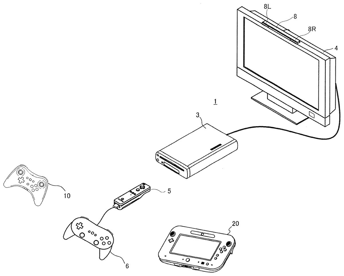
DESCRIPTION OF EMBODIMENTS A game system1including a game apparatus according to an embodiment of the present invention will be described with reference toFIG. 1.FIG. 1is an external view of the game system1. Hereinafter, a game apparatus and a game program according to the present embodiment will be described, taking a stationary game apparatus as an example. Referring toFIG. 1, the game system1includes a television receiver (hereinafter referred to simply as a “television”)2, a game apparatus3, a first controller5, a second controller10, a third controller20, and a marker section8. Each of the first controller5, the second controller10, and the third controller20includes a communication section capable of wireless communication, and is wirelessly connected to the game apparatus3when it is used. As for a communication standard and a protocol adopted for the wireless communication, the first controller5and the second controller10adopt the same communication standard and the same protocol, while the third controller20adopts a communication standard and a protocol different from those of the first and second controllers5and10. The first controller5and the second controller10communicate with the game apparatus3by using, for example, “Bluetooth (registered trademark)” as a communication standard, and a proprietary first protocol as a protocol. The third controller20communicates with the game apparatus3by using, for example, “WiFi Direct” and a proprietary second protocol. Further, an extended controller6is wire-connected to the first controller5via a connector53described later. In this system, a game process is executed on the game apparatus3based on a game operation using the first controller5, the second controller10, and the third controller20. These controllers can be used in combination (simultaneously). For example, if each of three players uses one of the controllers, the three players can play a game simultaneously. The game apparatus3has downward compatibility with another existing game apparatus (not shown). In other words, the game apparatus3has compatibility with the another game apparatus ...
DESCRIPTION OF EMBODIMENTS
A game system1including a game apparatus according to an embodiment of the present invention will be described with reference toFIG. 1.FIG. 1is an external view of the game system1. Hereinafter, a game apparatus and a game program according to the present embodiment will be described, taking a stationary game apparatus as an example. Referring toFIG. 1, the game system1includes a television receiver (hereinafter referred to simply as a “television”)2, a game apparatus3, a first controller5, a second controller10, a third controller20, and a marker section8. Each of the first controller5, the second controller10, and the third controller20includes a communication section capable of wireless communication, and is wirelessly connected to the game apparatus3when it is used. As for a communication standard and a protocol adopted for the wireless communication, the first controller5and the second controller10adopt the same communication standard and the same protocol, while the third controller20adopts a communication standard and a protocol different from those of the first and second controllers5and10. The first controller5and the second controller10communicate with the game apparatus3by using, for example, “Bluetooth (registered trademark)” as a communication standard, and a proprietary first protocol as a protocol. The third controller20communicates with the game apparatus3by using, for example, “WiFi Direct” and a proprietary second protocol.
Further, an extended controller6is wire-connected to the first controller5via a connector53described later. In this system, a game process is executed on the game apparatus3based on a game operation using the first controller5, the second controller10, and the third controller20. These controllers can be used in combination (simultaneously). For example, if each of three players uses one of the controllers, the three players can play a game simultaneously.
The game apparatus3has downward compatibility with another existing game apparatus (not shown). In other words, the game apparatus3has compatibility with the another game apparatus (hereinafter referred to as a subordinate model), and has improved performance (that is, the game apparatus3corresponds to a superordinate model). The first controller5is identical to a controller that is used as a standard controller of the subordinate model (the extended controller6can also be used as an extended controller of the subordinate model). That is, the first controller5is a controller that can be used by (that is compatible with) both the game apparatus3of the present embodiment and the subordinate model.
Note that the second controller10and the third controller20cannot be used by the subordinate model. For example, the second controller10is allowed to establish wireless communication with the subordinate model (because the second controller10and the subordinate model use the same communication standard). However, after wireless connection has been established, the second controller10recognizes that the connection destination is the subordinate model, and performs a control to disconnect the wireless connection. Thus, the second controller10cannot be substantially used by the subordinate model.
Next, the first controller5will be described with reference toFIG. 2.FIG. 2is a perspective view of the first controller5seen from a top rear side thereof.
With reference toFIG. 2, the first controller5includes a housing51and an operation section52including a plurality of operation buttons provided on the surface of the housing51. The housing51of the present embodiment has a substantially parallelepiped shape extending in a longitudinal direction from front to rear. The overall size of the housing51is small enough to be held by one hand of an adult or even a child. For example, the housing51is formed by plastic molding.
At the center of a front part of a top surface of the housing51, a cross key52ais provided. The cross key52ais a cross-shaped four-direction push switch. The cross key52aincludes operation portions corresponding to four directions (front, rear, right and left), which are respectively located on cross-shaped projecting portions arranged at intervals of 90 degrees. A player selects one of the front, rear, right and left directions by pressing one of the operation portions of the cross key52a. Through an operation of the cross key52a, the player can, for example, indicate a direction in which a player character or the like appearing in a virtual game world is to move, or give an instruction to select one of a plurality of options.
The cross key52ais an operation section for outputting an operation signal in accordance with the above-described direction input operation performed by the player. However, such an operation section may be provided in another form. For example, the cross key52amay be replaced with an operation section that has four push switches extending in four directions corresponding to a cross, and may output an operation signal in accordance with one of the four push switches pressed by the player. In addition to the four push switches, a center switch may be provided at the center of the four push switches to form a composite operation section including the four push switches and the center switch. Alternatively, the cross key52amay be replaced with an operation section which includes an inclinable stick (so-called a joystick) projecting from a top surface of the housing51and which outputs an operation signal in accordance with an inclining direction of the stick. Still alternatively, the cross key52amay be replaced with an operation section which includes a disc-shaped and horizontally slidable member and which outputs an operation signal in accordance with a sliding direction of the disc-shaped member. Still alternatively, the cross key52amay be replaced with a touch pad.
Behind the cross key52aon the top surface of the housing51, a plurality of operation buttons52bto52gare provided. Each of the operation buttons52bto52gis an operation section for outputting an operation signal assigned thereto, when the player presses a head thereof. For example, functions as a No. 1 button, a No. 2 button, and an A button are assigned to the operation buttons52bto52d, respectively. Also, functions as a minus button, a home button, and a plus button are assigned to the operation buttons52eto52g, respectively. Operation functions are assigned to the operation buttons52bto52gin accordance with a game program executed by the game apparatus3. In an exemplary arrangement shown inFIG. 2, the operation buttons52bto52dare arranged in a line at the center on the top surface of the housing51in a front-rear direction. The operation buttons52eto52gare arranged on the top surface of the housing51in a line in a left-right direction between the operation buttons52band52d. The operation button52fhas a top surface thereof buried in the top surface of the housing51, so as not to be inadvertently pressed by the player.
In front of the cross key52aon the top surface of the housing51, an operation button52his provided. The operation button52his a power switch for turning on or off the body of the game apparatus3by remote control. The operation button52halso has a top surface buried in the top surface of the housing51, so as not to be inadvertently pressed by the player.
Behind the operation button52con the top surface of the housing51, a plurality of LEDs54ato54dare provided. Here, a controller type (number) is assigned to the first controller5such that the controller5is distinguishable from other controllers (the second controller10, the third controller20, and other first controllers5). For example, the LEDs54ato54dare used for informing the player of the controller type that is currently set in the first controller5. Specifically, when the first controller5transmits transmission data to the game apparatus3, one of the plurality of LEDs54ato54dis turned on in accordance with the controller type.
On the top surface of the housing51, sound holes for outputting sound from a speaker to the external space are formed between the operation button52band the operation buttons52eto52g.
On a back surface of the housing51, a recessed portion is formed. The recessed portion on the back surface of the housing51is formed in a position in which an index finger or middle finger of the player is positioned when the player holds the first controller5with one hand and points a front portion thereof to the markers8L and8R. On a slope surface of the recessed portion, an operation button52i(not shown in the figure) is provided. The operation button52iis an operation section acting as, for example, a B button.
On the top surface of the housing51, an image pickup element55forming a part of an imaging information calculation section59described later is provided. The imaging information calculation section is a system for: analyzing image data of an image taken by the first controller5; identifying an area having a high brightness in the image; and detecting a position of a center of gravity, a size and the like of the area. The imaging information calculation section59has, for example, a maximum sampling period of approximately 200 frames/sec, and therefore, can trace and analyze even a relatively fast motion of the first controller5.
On the rear surface of the housing51, a connector53is provided. The connector53is, for example, an edge connector, and is used for engaging and connecting the extended controller6or the like with a connection cable.
Next, the extended controller6will be described. The extended controller6is a game controller that is held and operated with both hands. As shown inFIG. 3, the extended controller6includes two analog sticks61aand61b, a cross key63a, and operation buttons63bto63h, on a front surface of a housing having left and right grips68. The two analog sticks are provided on the lower side of the front surface of the housing (near the bottom surface of the housing). The cross key63ais positioned above the analog stick61a, and the operation buttons63eto63hare positioned above the analog stick61b. The operation buttons63bto63dare positioned above the analog sticks61aand61band between the cross key63aand the operation buttons63eto63h.
Operation buttons63iand63jare provided at positions on an upper surface of the housing, which positions are reached by left and right index fingers when the extended controller6is held with both hands, respectively. Further, operation buttons63kand63l(not shown) are provided on the back surface side relative to the operation buttons63iand63j, respectively. Further, a connection cable64extends from the upper surface of the housing, and a connector65for connecting the extended connector6to the connector53of the first controller5is provided at an end of the connection cable. By connecting the extended controller6to the first controller5via the connection cable64, the extended controller6becomes usable. Specifically, as described later, the content of operation performed on the extended controller6is transmitted to the first controller5(a first control section56described later), and the first controller5generates transmission data based on the content of operation, and thereby the content of operation is transmitted from the first controller5to the game apparatus3.
Next, the internal configurations of the first controller5and the extended controller6connected to the first controller5will be described with reference toFIG. 4.FIG. 4is a block diagram illustrating the configurations of the first controller5and the extended controller6connected to the first controller5.
With reference toFIG. 4, the first controller5includes a first control section56, a digital button section501corresponding to the above-mentioned cross key52aand operation buttons52bto52i, a sensor section57, an LED section502corresponding to the above-mentioned LEDs54ato54d, a vibration section (vibrator)58, a first microcomputer59, and a connector53. The first controller5further includes a speaker, a sound IC, a battery, and the like, which are not shown inFIG. 4.
The sensor section57includes an imaging information calculation section571, an acceleration sensor572, and an angular velocity sensor573. The imaging information calculation section571includes an infrared filter, a lens, an image pickup element55, and an image processing circuit, which are not shown inFIG. 4. The infrared filter allows only infrared light to pass therethrough, among light incident on the front surface of the first controller5. The markers8L and8R provided in the vicinity of the display screen of the television2are infrared LEDs each outputting infrared light forward from the television2. Therefore, by providing the infrared filter, images of the markers8L and8R can be taken accurately. The lens converges the infrared light that has passed through the infrared filter, and outputs the infrared light to the image pickup element55. The image pickup element55is a solid-state image pickup element such as a CMOS sensor and a CCD, and takes an image of the infrared light converged by the lens. Accordingly, the image pickup element55takes an image of only the infrared light that has passed through the infrared filter, and generates image data of the image. The image data generated by the image pickup element is processed by the image processing circuit. The image processing circuit calculates the position of an imaging target (the markers8L and8R) in the taken image. Further, the image processing circuit outputs the position of the imaging target to the first control section56.
The acceleration sensor572detects an acceleration (including gravitational acceleration) of the first controller5, that is, detects a force (including gravity) applied to the first controller5. Then, the acceleration sensor572outputs the detected acceleration to the first control section56. Further, the angular velocity sensor573detects an angular velocity (per unit time) with respect to a yaw angle (an angular velocity around the Y axis), an angular velocity (per unit time) with respect to a roll angle (an angular velocity around the Z axis), and an angular velocity (per unit time) with respect to a pitch angle (an angular velocity around the X axis). The angular velocity sensor573outputs the detected angular velocities to the first microcomputer59.
The first control section56includes a memory, a wireless module, an antenna, and the like. With the use of the memory as a storage area during the process, the first control section56controls the wireless module that wirelessly transmits transmission data to the game apparatus3. Further, the first control section56controls the operations of the LED section502, the vibration section58, the sound IC, and the like, based on data received by the wireless module from the game apparatus3via the antenna. Further, the first control section56is connected to the first microcomputer59. The first microcomputer59is connected to the angular velocity sensor573. The first microcomputer59detects an input to the angular velocity sensor573, and notifies the first control section56of the detected input. Therefore, the first control section56can obtain, via the first microcomputer59, data outputted from the angular velocity sensor573. The first microcomputer59is further connected to the connector53. That is, the first microcomputer59is connected to a second control section66of a later-described extended controller6via the connector53, and therefore can obtain data (operation data and the like regarding the extended controller6) outputted from the second control section66. Then, the first microcomputer59outputs, to the first control section56, the data obtained from the second control section66. Based on these pieces of data, the first control section56generates data indicating the content of operation (transmission data300described later), and transmits the transmission data to the game apparatus3by using the wireless module (generation of the transmission data will be described later in detail). Thus, it is possible to notify the game apparatus3of the contents of operations performed on the first controller5and the extended controller6.
In the exemplary configuration shown inFIG. 4, data outputted from the digital button section501is directly input to the first control section56. However, the first microcomputer59may be provided between the first control section56and the digital button section501. That is, the first microcomputer59may detect an operation performed on the digital button section501, and notify the first control section56of the detected operation. In this case, a combination of the first control section56and the first microcomputer59can be regarded as a detection section having a function of detecting operations on the operation sections such as the digital button section501.
Further, inFIG. 4, the extended controller6includes a second control section66, an analog stick section601corresponding to the analog sticks61aand61b, a digital button section602corresponding to the cross key63aand the operation buttons63bto63l, and a connector65.
The second control section66detects inputs to the analog stick section601and the digital button section602, and generates extended controller data308described later. Then, the second control section66outputs the generated data to the first control section56via the connector65and the first microcomputer59.
Note that the extended controller6itself does not have a battery or the like, and is supplied with power from the battery of the first controller5via the connector65.
Next, transmission data transmitted from the first controller5to the game apparatus3will be described. The transmission data mainly includes data indicating the contents of operations performed on the first controller5and the extended controller6by the player (data indicating a remaining battery level or the like is also included). In the present embodiment, as for a data format (which defines data to be included, the length of the data, and the like, and is referred to simply as “format” hereinafter) of the transmission data, a plurality of formats have been defined in advance, and a developer is allowed to select and use any of the plurality of formats depending on the content of a game to be developed.
FIG. 5illustrates an example of a format of the transmission data300, which is used in the present embodiment. The transmission data300consists of a header region301, a base region302, and an extended region303. In the present embodiment, the transmission data300is, for example, data having a fixed length of 27 bytes. In the present embodiment, whichever format is used, the byte length of the header region is fixed to 6 bytes (the lengths of the base region302and extended region303vary depending on the used format). Further, whichever format is used, at least the header region301is included in the transmission data300.
In the header region301, information (header information) including, for example, an ID for uniquely identifying the plurality of formats is stored. In the base region302, data indicating the pressing state of the digital button section501is stored. Data stored in the extended region303appropriately varies depending on, for example, the game content executed by the game apparatus3(in other words, an appropriate format is used according to the game content). For example, in a certain game process (a certain format), acceleration data obtained from the acceleration sensor572and angular velocity data obtained from the angular velocity sensor573are stored in the extended region303. In another game, data indicating the coordinates of the imaging target, which is obtained from the imaging information calculation section571, is stored in the extended region303. In still another game, the acceleration data, the angular velocity data, and the data indicating the coordinates of the imaging target are stored in the extended region303. As shown inFIG. 1, when the extended controller6is connected to the first controller5and a format that uses the extended controller6is designated, data indicating the content of operation performed on the extended controller6is stored in the extended region303.
The present embodiment will be described for the case where the extended controller6is connected to the first controller5. That is, the present embodiment will be described on assumption that, among the plurality of formats, the format is selected and used in which the data indicating the content of operation performed on the extended controller6is stored in the extended region303. Specifically, as an example of a format of the transmission data300, a format shown inFIG. 6is used. In this format, it is defined that the header region301has 6 bytes, the base region302has 10 bytes, and the extended region303has 11 bytes. Since the first controller5can be used by (is compatible with) the subordinate model as described above, this format can also be used by the subordinate model. In other words, the format used by the subordinate model is used in the game process (game development) of the game apparatus3.
InFIG. 6, a report ID305that is an ID for uniquely identifying the plurality of formats is stored in the header region301. In addition, information that allows the game apparatus3to identify the controller is appropriately stored in the header region301.
In the base region302, digital button data306indicating the pressing state of the digital button section501is stored. The data stored in the base region302is generated by the first control section56based on the output from the digital button section501.
In the extended region303, extended controller data308(hereinafter simply referred to as extended data) is stored. The extended data308is generated by the second control section66based on the outputs from the digital button section602and the analog stick section601of the extended controller6. That is, the extended data308indicates the content of operation performed on the extended controller6. The generated extended data308is outputted from the second control section66to the first control section56(via the connector65).
The first control section56stores, in the extended region303, the extended data308transmitted from the second control section66as well as the data stored in the base region302, and sets, in the header region301, the report ID305corresponding to the format shown inFIG. 6, thereby generating the transmission data300. Then, the first control section56transmits the transmission data300to the game apparatus3to notify the game apparatus3of the contents of operations performed on the first controller5and the extended controller6by the player.
In the above-described embodiment, only the header region301has a fixed length. However, in another embodiment, the base region302and the extended region303may have fixed lengths (data to be stored therein appropriately varies).
Hereinafter, the second controller10will be described.FIG. 7illustrates an external view of the second controller10.FIG. 7Ais a left side view of the second controller10,FIG. 7Bis a front view of the second controller10,FIG. 7Cis a right side view of the second controller10,FIG. 7Dis a rear view of the second controller10,FIG. 7Eis a top view of the second controller10, andFIG. 7Fis a bottom view of the second controller10. The second controller10mainly includes: a housing102having left and right grips103L and103R (hereinafter also collectively referred to as grips103); and an operation section that includes two analog sticks projecting from openings provided at a front surface of the housing102, and a plurality of operation buttons (described later). The housing102of the present embodiment, when viewed from the front side thereof, has a gentle trapezoid shape with its left-right direction being a longitudinal direction. The housing102is a little recessed at its upper side, and is recessed more at its lower side than at the upper side. In other words, the housing102is shaped such that the grips103L and103R extend toward the bottom surface side (toward the player when he/she holds the controller). The front surface of the housing102is substantially flat except the portions where the analog sticks are provided. The portions where the analog sticks are provided are slightly raised. The grips103L and103R are shaped so as to gently curve from the front surface to the back surface. Note that the housing102of the present embodiment is formed by plastic molding, for example.
A first analog stick111(hereinafter referred to as a left stick) is provided on the left end of the front surface of the housing102and in the vicinity of the upper surface of the housing102, and a second analog stick112(hereinafter referred to as a right stick) is provided on the right end of the front surface of the housing102and in the vicinity of the upper surface of the housing102. More specifically, the left stick111is provided at a position that allows a player to operate the left stick111with a thumb of his/her left hand that holds the grip103L (more preferably, a position on which the thumb of the left hand that holds the grip103L is naturally put). The right stick112is provided at a position that allows the player to operate the right stick112with a thumb of his/her right hand that holds the grip103R (more preferably, a position on which the thumb of the right hand that holds the grip103R is naturally put). Each of the left stick111and the right stick112is a stick that can be tilted down to an arbitrary direction chosen from a 360° range, and is used by the player to give an instruction about an arbitrary direction. Further, each of the left stick111and the right stick112can be pushed toward the back surface. Thus, the left stick111and the right stick112also serve as push buttons. The left stick111and the right stick112act in accordance with a program executed by an information processing apparatus (e.g., a game apparatus) to which the controller is connected. Since the interval between the left stick111and the right stick112is increased as compared to the conventional controller, even when the player tilts down the left stick111and the right stick112toward the center of the housing102, the interval between the left and right thumbs of the player is not narrow, which allows the player to perform operations easily.
A cross key (also referred to as a direction key)21is provided at a position to the left of the substantial center position on the front surface of the housing102, and near the center position relative to the left stick111, at which the player is allowed to operate the cross key with the thumb of the left hand that holds the grip103L. Specifically, the cross key121is provided at a position to the right of and beneath the left stick111. The cross key121is a cross-shaped four-direction push switch. The cross key121includes operation portions corresponding to the four directions (front, rear, right and left), which are respectively located on cross-shaped projecting portions arranged at intervals of 90 degrees. The player selects one of the front, rear, right, and left directions by pressing one of the operation portions of the cross key121. The cross key121acts in accordance with a program executed by an information processing apparatus (e.g., a game apparatus) to which the controller is connected. The shape of the cross key121is not limited to that shown inFIG. 7B. The cross key121may have any shape as long as it allows the player to input the four directions. For example, the cross key121may have a shape of a round base with a protruding cross shape, or may be a set of four keys separated from each other.
Further, operation buttons122A to122D (hereinafter also referred to as a first operation button set) are positioned so as to form a cross shape, i.e., positioned rightward, downward, leftward, and upward, respectively, in an area to the right of the substantial center of the front surface of the housing102, and near the center of the housing102relative to the right stick112, at which the player is allowed to operate the operation buttons122A to122D with the thumb of the right hand that holds the grip103R. More specifically, the operation buttons122A to122D are positioned so as to form a cross shape, i.e., positioned rightward, downward, leftward, and upward, respectively, in an area to the left of and beneath the right stick112. The operation buttons122A to122D are appropriately assigned functions, respectively, in accordance with a program executed by the information processing apparatus to which the second controller10is connected. For example, the operation buttons122A to122D are used for determination operation, cancellation operation, and the like.
As described above, since the cross key121is positioned to the right of and beneath the left stick111, the ball of the thumb of the left hand of the player reaches the position of the cross key121when the player moves the thumb with the base of the thumb being a fulcrum point. In other words, the player is allowed to move the ball of the thumb to the position of the cross key121by only moving the thumb to the right with the base of the thumb being a fulcrum point, without particularly changing the position of holding the grip103L. In addition, the player is allowed to return the thumb to the position of the left stick111by moving the thumb to the left. That is, the player is allowed to easily move the thumb between the left stick111and the cross key121, thereby improving the operability. In other words, when the player operates the cross key121, it is possible to avoid the situation that the stick is positioned between the tip of the thumb (the position of the cross-key) and the base of the thumb, and impedes the player's operation, which results in reduction in the operability.
Likewise, since the first operation button set (operation buttons122A to122D) is positioned to the left side of and beneath the right stick112, the player is allowed to move the thumb of the right hand between the right stick112and the first operation button set by only moving the thumb with the base of the thumb being a fulcrum point. Thereby, the player is allowed to easily move the thumb between the right stick112and the first operation button set, and thus the operability is improved.
An L button125L is provided at the left end of the upper surface of the housing102and near the front surface of the housing102, and a ZL button126L is provided beneath the L button125L (near the back surface relative to the L button125L). An R button125R is provided at the right end of the upper surface of the housing102and near the front surface of the housing102, and a ZR button126R is provided beneath the R button125R (near the back surface relative to the R button125R). The L button125L is provided at a position reached by an index finger of a left hand that holds the grip103L, and the ZL button126L is provided at a position reached by a middle finger and a ring finger of the left hand. The R button125R is provided at a position reached by an index finger of a right hand that holds the grip103R, and the ZR button126R is provided at a position reached by a middle finger and a ring finger of the right hand. The L button125L, the R button125R, the ZL button126L, and the ZR button126R are appropriately assigned functions, respectively, in accordance with a program executed by the information processing apparatus.
Further, system operation buttons123A to123C are provided at a position in the center of the front surface of the housing102, near the upper surface of the housing102, and between the left stick111and the right stick112. The system operation buttons123A to123C (hereinafter also referred to as a second operation button set) are assigned functions as a minus button, a home button, a plus button, and the like. These system operation buttons123A to123C are assigned operation functions, respectively, in accordance with a program executed by the information processing apparatus to which the second controller10is connected. In the present embodiment, for example, operations to be directly controlled by the system of the game apparatus are assumed. For example, when the home button123B is pressed, game processing, even if it is being executed, is stopped, and the screen is changed to the home screen. When the minus button123A or the plus button123C is pressed, the image displayed in the home screen is changed (paging or scrolling is performed). Since the left stick111and the right stick112are positioned near the both ends of the upper surface, respectively, a sufficient space is secured between the sticks, and a plurality of system operation buttons can be provided in the space such that the sticks do not impede the player from operating the system operation buttons.
Further, a power operation button128is provided at a position in the center of the front surface of the housing102, near the bottom surface of the housing102, and between the cross key121and the operation buttons122A to122D (first operation button set). In other words, the cross key121and the first button set are spaced apart from each other at a certain interval in the left-right direction (horizontal direction) inFIG. 7B, and the power operation button128is positioned between (inFIG. 7B, in the middle between) the cross key121and the first button set. The power operation button128is a power switch for remote-controlling the power of the information processing apparatus body to be on and off. The power operation button128has a top surface buried in the front surface of the housing102so as not to be inadvertently pressed by the player. Since the left stick111and the right stick112are positioned near the upper surface, the player need not move his/her fingers beyond the sticks when pressing the system operation buttons123A to123C or the power operation button128, and thus the player can easily press the buttons.
Further, a plurality of indicators are provided on the front surface of the housing102and near the bottom surface relative to the power operation button128. Specifically, LEDs131A to131D are provided. A plurality of controllers may be connected to the information processing apparatus to which the controller10is connected. A controller type (number) is assigned to the second controller10such that the second controller10is distinguishable from other controllers. The LEDs131A to131D are used for informing the player of the controller type that is currently set in the second controller10. The controller number is instructed from the information processing apparatus. Specifically, while the second controller10is communicating with the information processing apparatus, one of the plurality of LEDs131A to131D is turned on in accordance with an instruction from the information processing apparatus. The LEDs131A to131D are provided between and beneath the cross key121and the operation buttons122A to122D, and the space between the cross key121and the operation buttons122A to122D is increased at the lower side due to the arrangement of the operation buttons122A to122D, and therefore, a sufficient space for providing the plurality of LEDs is secured at the lower side. Further, while there is a case where the player moves the fingers inward beyond the positions of the sticks when operating the sticks, it is rare that the player moves the fingers inward beyond the positions of the buttons when operating the buttons, and therefore, the plurality of LEDs are less likely to be covered with the fingers during the operation. Accordingly, the LEDs are highly visible during the operation.
Further, a charging indicator132is provided near the upper surface of the housing102relative to the second operation button set. The charging indicator132is used for informing the player of the remaining battery level of the second controller10, and the state of charge of the second controller10, for example. For example, the charging indicator132can inform the player of the state of charge by using colors of an LED. In contrast to the LEDs131A to131D, the charging indicator132of the present embodiment is solely provided in a broad area on the housing, which area is not likely to be covered with the player's hand during the operation, and therefore, is noticeable, which allows the player to easily find a change of the indicator, for example, a change in the color of the indicator. Accordingly, the player easily recognizes a reduction in the remaining battery level.
Further, as shown inFIG. 7E, a charging connector133is provided at a position in the center of the upper surface of the housing102and near the front surface of the housing102. The charging connector133is, for example, a connector corresponding to a mini USB terminal, and is capable of charging the second controller10when it is connected to a power supply by using a predetermined cable.
Further, as shown inFIG. 7D, on the back surface of the housing102, a battery cover135is provided in a center area sandwiched between the left and right grips. A battery is stored inside the cover. Further, the center area of the housing102(hereinafter referred to as a battery storage area) is recessed relative to the left and right grips and the area where the ZL button126L and the ZR button126R are present (refer toFIGS. 7A, 7C, 7E, and 7F). That is, the center area where the battery is stored is recessed, and only this area is reduced in thickness (in other words, only the grips103L and103R and the area where the ZL button126L and the ZR button126R are stored are raised). In the conventional art, since the sticks are positioned near the center of the housing, the thickness of the center portion of the housing is somewhat increased due to influence of the sizes of parts, and the like. In contrast, in the present embodiment, since the left stick111and the right stick112are provided outward when viewed from the back surface (near the both ends of the front surface), the thickness of the center area is reduced, which allows the player to easily hold the housing102. Further, two small holes are opened in an upper end portion of the battery cover135. In one of the holes (the left-side hole inFIG. 7D), a connect button136is provided, which is used for establishing wireless connection (pairing) between the second controller10and the information processing apparatus. In the other hole (the right-side hole inFIG. 7D), a reset switch137for resetting the second controller10is provided.
Further, a vibrator that generates vibration based on a control signal from the information processing apparatus may be provided inside the grips103. Preferably, the vibrator is provided inside the grip103L. In other words, it is preferable that the vibrator be included in the left stick111that is supposed to be used mainly for direction input operation, or in a grip on the side where the cross key121is present. When the player operates the second controller10with his/her both hands, particularly when the player continuously operates the cross key121, more force is applied to the left hand (the left hand holds the grip more tightly than the right hand). Therefore, it is considered that the second controller10is more likely to be supported by the hand which mainly performs direction control, and vibration is more likely to be transmitted to the player when the vibrator is provided in the grip103L.
In addition, a communication section (a first control section201described later) for wireless communication with the information processing apparatus is also included in the housing102.
Hereinafter, the internal configuration of the second controller10will be described with reference toFIG. 8.FIG. 8is a block diagram illustrating the configuration of the second controller10. InFIG. 8, the second controller10includes a first control section201, a second control section202, a second microcomputer203, a first digital button section204, a second digital button section205, an analog stick section206(including a function of an analog stick as a push switch), a vibration section (vibrator)207, an LED section208, a battery control section209, and a battery210. The first digital button section204corresponds to the first operation button set and the second operation button set (the cross key121, the operation buttons122A to122D, and the system operation buttons123A to123C) among the plurality of digital buttons provided on the second controller10. The second digital button section205corresponds to the L button125L, the R button125R, the ZL button126L, and the ZR button126R. The analog stick section206corresponds to the left stick111and the right stick112. The LED section208corresponds to the LEDs131A to131D and the charging indicator132. These sections are electrically connected to each other. In other words, the second controller10is configured by roughly integrating the hardware configurations of the first controller5and the extended controller6. Further, power is supplied to each section via the battery control section209that is supplied with power from the battery210.
With reference toFIG. 8, the first control section201is electrically connected to the second control section202(by a I2C bus, for example). The first control section201is also connected to the second microcomputer203. The second microcomputer203detects an input to the first digital button section204, and notifies the first control section201of the detected input. Further, the second microcomputer203is connected to a power operation button128and a connect button136. The second microcomputer203detects inputs to these buttons, and notifies the first control section of the detected inputs. The first control section201periodically confirms the input state of each button with the second microcomputer203.
A signal indicating an input operation performed on the first digital button section203is output to the second microcomputer203and the second control section202. The number of the buttons included in the first digital button section204is equal to the number of the buttons provided on the first controller5(except the power button). That is, regarding input operations performed on the buttons provided on the second controller10corresponding in number to the buttons provided on the first controller5, the input operations can be output to both the first control section201(via the second microcomputer203) and the second control section202.
On the other hand, input operations performed on the second digital button section205and the analog stick section206are output to only the second control section202.
The fundamental hardware configuration of the first control section201is substantially identical to that of the first control section56of the first controller5, and includes a memory, a wireless module, and an antenna. The content of (software-like) control of the first control section201basically corresponds to that of the first control section56of the first controller5. However, in contrast to the first control section56, the first control section201in the second controller10does not perform such control as to include, in operation data (a base region302described later) to be transmitted to the game apparatus3, the result of detection of the input operation performed on the first digital button section204. Thus, the first control section201basically performs similar control to that of the first control section56except that software control to include, in the operation data, the input operation performed on the first digital button section204is not performed. That is, only by slightly changing the control, a control section that is similar in hardware (or includes similar components) to the first control section56can be used as the first control section201of the second controller10.
Further, the first control section201is able to generate and transmit transmission data by using any of the plurality of formats used in the data transmission by the first controller5(more precisely, the first control section201may use a format that uses the extended region among the plurality of formats). In the present embodiment, the first control section201generates, as transmission data to be transmitted to the game apparatus3, transmission data in the same format as the transmission data300shown inFIG. 6. That is, the first control section201is able to generate transmission data300by the format which defines that the header region301has 6 bytes, the base region302has 10 bytes, and the extended region303has 11 bytes. However, as described above, the first control section201does not perform control to include, in the base region302, the result of detection performed on the first digital button section203. As a result, transmission data300as shown inFIG. 9is generated in which the content of data in the base region302is null data corresponding to 10 bytes.
The fundamental hardware configuration of the second control section202is identical to that of the second control section66in the extended controller6, and the content of control thereof is nearly identical to that of the second control section66. That is, the second control section202performs detection of inputs to the first digital button section204and the second digital button section205, and detection of input to the analog stick section206. Based on the detection results, the second control section202generates extended data308. Further, the second control section202communicates with the battery control section209to obtain information indicating the remaining battery level and the charging state. The second control section202includes, in the extended data308, the information obtained from the battery control section209. Then, the second control section202outputs the generated extended data308to the first control section201.
An example of the content of the extended data308generated by the second control section202is shown inFIG. 10. With reference toFIG. 10, data corresponding to upper 8 bytes of 11 bytes are assigned to data indicating the result of detection of input to the analog stick section204(specifically, 2 bytes for the X axis of the left stick111, 2 bytes for the Y axis thereof, 2 bytes for the X axis of the right stick112, and 2 bytes for the Y axis thereof). Data corresponding to the remaining 3 bytes are assigned to the result of detection of inputs (digital button data) to the cross key121, the first button set, the system operation buttons123A to12C, the L button125L, the R button125R, the ZL button126L, the ZR button126R, and the left and right sticks111and112as push buttons, and to data (battery-related data) indicating the remaining battery level and the charging state, for example.
Next, the third controller20shown inFIG. 1will be described. The third controller20is connected to the game apparatus3by using a wireless communication protocol different from that used by the first controller5and the second controller10, and can be used in combination with the first controller5and the second controller10. As shown inFIG. 11, the third controller20includes a housing which generally has a horizontally long plate-like rectangular shape. This housing is small enough to be held by a user. A display section21(e.g., an LCD) is provided near the center of the front surface of the housing. A touch panel22is provided on the screen of the display section. Further, the third controller20includes, as other operation means, two analog sticks23A and23B, and a plurality of operation buttons24A to24J. The analog stick23A is provided to the left of the display section21, and the analog stick23B is provided to the right of the display section21. The operation button24A (cross key) is provided to the left of the display section21and beneath the analog stick23A, and the operation buttons24B to24E are provided to the right of the display section21and beneath the analog stick23B. The operation buttons24F and24H are provided beneath the operation buttons24B to24E. The operation button24G is provided beneath the display section21, the operation button241is provided on the left end of the upper side surface of the housing, and the operation button24J is provided on the right end of the upper side surface of the housing.
A control section such as a microcomputer is provided inside the third controller20. The microcomputer detects inputs to the touch panel, the analog stick, and the operation buttons, generates operation data indicating the contents of the inputs, and transmits the operation data to the game apparatus3. Further, the microcomputer receives video data transmitted from the game apparatus3, and displays a predetermined video on the display section, based on the video data.
Since the content of control performed by the third controller20and data used for the control are not directly related to the present embodiment, detailed description thereof is omitted.
Hereinafter, an example of a flow of a controller recognizing process performed between the first controller5(the second controller10) and the game apparatus3, and an example of a flow of an operation data transmitting/receiving process performed after the recognition process, will be described with reference toFIG. 12. It is assumed that, in advance of processes described below, a so-called pairing process (a process of identifying the connection destination) between each controller and the game apparatus3has already been done.
Firstly, processes performed between the first controller5and the game apparatus3will be described. With reference toFIG. 12, firstly, a process of connecting the first controller5(the extended controller6may not be connected) to the game apparatus3is performed. In the present embodiment, after the game apparatus3is activated, the A button (operation button52d) of the first controller5is pressed, and thereby the first controller5is connected to (recognized by) the game apparatus3(a predetermined controller type is assigned to the first controller5). Thus, the first controller5becomes usable.
Specifically, in the game apparatus3, a process of displaying, on the television2, a message that prompts the player to “press the A button of the controller” is executed (P1). In another embodiment, such a message may not be displayed.
When the player presses the A button of the first controller5, the first control section56detects that the A button is pressed. Then, the first control section56starts a connection process described below. The A button is an example, and another button may be pressed.
Next, a connection process of establishing wireless connection between the first control5and the game apparatus3is performed between the first control section56and the game apparatus3(P3, P4). For example, wireless connection between the first controller5and the game apparatus3is established by executing a predetermined process based on the protocol of Bluetooth (registered trademark). This process may include a process of determining a controller type to be assigned to the controller connected to the game apparatus, and lighting any of the LEDs54ato54din accordance with the determined controller type.
After the wireless connection between the first controller5and the game apparatus3has been established, transmission of transmission data (operation data) and a process based on the transmission data are appropriately executed between the first control section56and the game apparatus3. Specifically, in accordance with an operation performed on the first controller5by the player, the first control section56generates data indicating the content of the operation in the base region302(P5). If the extended controller6is connected to the first controller5and the extended controller6is being operated, the second control section66generates the content of the extended data308, and outputs the extended data308to the first control section56via the microcomputer59(P6). The first control section56includes, in the transmission data300, the extended data308outputted from the second control section66via the microcomputer59, and transmits the transmission data300to the game apparatus3(in this case, the format described with reference toFIG. 6and the report ID305corresponding to the format are used) (P7). Further, the first control section56receives various kinds of data transmitted from the game apparatus3, and appropriately controls the first controller5(e.g., vibration control or audio output). The game apparatus3performs a predetermined process based on the data transmitted from the first controller5, and transmits, according to need, data for controlling the first controller5to the first control section56(P8). Thereafter, the process steps P5to P8are appropriately repeated.
Next, processes to be performed between the second controller10and the game apparatus3will be described. In the present embodiment, after the game apparatus3is activated, the A button (operation button122A) of the second controller10is pressed, and thereby the controller10is connected to the game apparatus3. Thus, the controller10becomes usable.
When the player presses the A button of the second controller10, the microcomputer203detects that the A button is pressed, and notifies the first control section201of this effect (P9). The A button is an example, and another button included in the first digital button section204may be pressed.
Upon receiving the notification that the A button has been pressed, the first control section201starts a connection process for establishing wireless connection between the first controller5and the game apparatus3(P4, P10). This process is similar to the connection process performed between the first controller5and the game apparatus3.
After the wireless connection between the second controller10and the game apparatus3has been established, transmission of operation data and a process based on the operation data are appropriately executed between the first control section201(the second controller10) and the game apparatus3. At this time, the content of control performed by the first control section201is as follows. That is, detection of input to the first digital button section204by the microcomputer203and output of the detected content to the first control section201are performed, but the first control section201performs control such that data indicating the result of the detection performed on the first digital button section204is not included in the base region302. On the other hand, the second control section202detects the contents of inputs to the first digital button section204, the second digital button section205, and the analog stick section206. Based on the detection result, the second control section202generates extended data308, and outputs the extended data308to the first control section202(P11). The first control section201stores the extended data308in the extended region303, and sets a predetermined report ID305with the base region302being filled with null data, thereby generating transmission data300. Then, the first control section201transmits the transmission data300to the game apparatus3. The game apparatus3performs a predetermined process based on the data transmitted from the second controller10, and transmits, according to need, data for controlling the second controller10to the first control section202(P8, P12). Thereafter, the process steps P11to P12are appropriately repeated.
That is, as for the content of the transmission data300transmitted from the second controller10, the base region302is filled with null data, and therefore, the transmission data300substantially consists of the header region301and the extended region303. That is, the data indicating the content of operation performed on the second controller10is transmitted to the game apparatus3substantially by using only the extended region303. As described above, the base region302itself is secured although its content is null data, and the base region302is included in the transmission data300. Therefore, the same data format as that used when the first controller5transmits the transmission data to the game apparatus3can be used as the format of the transmission data in the second controller10. In other words, the developer of game software is allowed to perform development without being conscious of distinction between the first controller5and the second controller10.
As described above, by configuring the second controller10so as to have the shape and button arrangement described with reference toFIGS. 7A to 7F, it is possible to provide a controller whose operability is improved as compared with that of the extended controller6. That is, the two analog sticks are positioned in the upper right portion and the upper left portion of the housing102, respectively, when the housing102is viewed from the front thereof, such that the player is allowed to operate the sticks with left and right thumbs when holding the grips103L and103R, respectively. Therefore, it is possible to secure a sufficient interval between the two sticks in the horizontal direction, thereby improving the operability of each analog stick.
Further, the cross key121and the first operation button set are positioned inside relative to the two analog sticks. Therefore, as compared to a controller in which a cross key (whose key top is lower than analog sticks) is positioned outside relative to the analog sticks (which are higher than the cross key), it is possible to avoid such a situation that the analog sticks that are higher than the cross key impede the player from operating the cross key. Thus, the operability is improved. The same can be said for the second operation button set. That is, since the second operation button set is positioned inside relative to the two analog sticks, the height of the analog sticks does not interfere with the player's fingers, which allows the player to easily operate these buttons.
Further, since the cross key121and the first operation button set are positioned with a certain interval between them, even if the left and right thumbs are put on the cross key121and the first operation button set, respectively, the thumbs are prevented from touching and interfering with each other, and thus the cross key121and the first operation button set are improved in operability. Further, as for movement of the left thumb between the left stick111and the cross key121and movement of the right thumb between the right stick112and the first operation button set, the player can move each thumb easily and naturally with the base of the thumb as a fulcrum point. Therefore, the player can easily operate them.
Further, since the parts of the analog sticks, each having a certain volume in the depth direction because of its configuration when provided on the housing102, are located in the upper right position and the upper left position of the housing102, respectively, it is possible to reduce the thickness of the battery storage area of the housing102(the area corresponding to the battery cover135when viewed from the back surface of the housing102). As a result, when the player holds the grips103L and103R with both hands, there is no obstacle to fingers put on the back surface, which allows the player to easily hold the grips103L and103R. In addition, the weight balance of the entire controller is appropriately adjusted in view of ease for holding, which contributes to improvement of operability.
Further, the above-described arrangement of the two analog sticks causes the left stick111and the L button125L to be positioned close to each other, and causes the right stick112and the R button125R to be positioned close to each other. As a result, it is possible to improve the operability of operation of the L button125L and the R button125R by using left and right index fingers with thumbs being put on the analog sticks. For example, it is possible to improve the operability in a case where either of the analog sticks and either of the L and R buttons125L and125R are operated simultaneously.
Further, as described above, the left stick111and the right stick112also serve as push buttons. Since the two analog sticks are positioned such that, when the player holds the grips103, thumbs of his/her both hands naturally touch the sticks, the player is allowed to push the analog sticks with the hands and fingers holding the grips103being in their natural positions, and moreover, the player is allowed to easily tilt the analog sticks in the natural positions.
Further, in the present embodiment, as described above, when transmitting the operation content from the second controller10to the game apparatus3, the same format as any of the plurality of formats of the transmission data used by the first controller5(more precisely, any of the formats using the extended region303) can be used. Therefore, the software asset used in the subordinate model can be utilized in the game apparatus3as the superordinate model. For example, when developing a game using the second controller10, the development knowhow of the subordinate model and the processes (library, module, and the like) used in the development of the subordinate model can be utilized in the processes in the game apparatus3, thereby reducing the burden on the game development and the like.
Further, in the present embodiment, the hardware configuration of the first control section201of the second controller10is substantially identical to that of the first control section56of the first controller5, and the content of control (function) performed by the first control section201of the second controller10is nearly identical to that performed by the first control section56of the first controller5. That is, the first control section56of the first controller5can be used (in terms of hardware and software) as the first control section201of the second controller10. Thereby, the cost for manufacturing the second controller10can be reduced. Further, since the second control section66of the extended controller6can be used as the second control section202, reduction in the manufacturing cost is similarly achieved.
(Modification)
In the above-described embodiment, as for the content of control performed by the first control section201of the second controller10, the content of operation performed on the first digital button section204is not included in the base region302(data in the base region302is not generated). Alternatively, for example, the result of detection performed on some buttons, specifically the system operation buttons123A to123C, may be stored in the base region302. These buttons are used for stopping the game process to return to the home screen, rather than for direct game operation. Therefore, when input operations performed on these buttons are included also in the base region302and transmitted, operation directly controlled by the system of the game apparatus3can be detected reliably, for example, recovery operation or the like can be executed securely.
INDUSTRIAL APPLICABILITY
The game system and the game controller according to the present embodiment can improve operability, utilize software asset of a subordinate model, and achieve reduction in the hardware cost, and therefore, are useful as game controllers or the like of various kinds of game apparatuses and personal computers.
DESCRIPTION OF THE REFERENCE CHARACTERS
1game system2monitor2aspeaker3game apparatus5first controller6extended controller8marker section10second controller20third controller21display section22touch panel23analog stick24operation button51housing52operation section53connector54LED55image pickup element61analog stick63operation button64connection cable65connector66grip section101controller102housing103L grip (left)103R grip (right)111left stick112right stick121cross key122A operation button122B operation button122C operation button122D operation button123A minus button123B home button123C plus button125L L button125R R button126L ZL button126R ZR button128power operation button131A LED131B LED131C LED131D LED132charging indicator133charging connector135battery cover136connect button137reset button
Claims
- A game system including at least a first game apparatus, a first game controller, and a second game controller, wherein the first game controller comprises: a first communication section that wirelessly communicates with the game apparatus;a first detection section that is able to generate first transmission data including a result of an input performed on a predetermined operation section;a first operation section that includes a plurality of keys, and is electrically connect ed to the first detection section;and a connector to which an extended controller is detachably connected, the extended controller including a second operation section that includes a plurality of keys, and a second detection section that is able to output, to the first detection section, second operation section detection data indicating the content of an input to the second operation section, wherein the first detection section detects at least an input to the first operation section, generates the first transmission data in which first operation section detection data indicating the result of the detection is included, and outputs the first transmission data to the first communication section, and the first communication section transmits, to the game apparatus, the first transmission data outputted from the first detection section, and the second game controller comprises: a second communication section that communicates with the game apparatus by using the same wireless protocol as that used by the first communication section;a third detection section that is able to generate second transmission data including a result of an input performed on a predetermined operation section;a fourth detection section;and a third operation section that includes a plurality of keys, and is electrically connected to the third detection section and the fourth detection section, wherein the third detection section and the fourth detection section are able to detect an input to the third operation section, the fourth detection section outputs, to the third detection section, third operation section detection data detected by the fourth detection section, the third detection section generates the second transmission data in which third operation section detection data detected by the third detection section is not included but the third operation section detection data outputted from the fourth detection section is included, and outputs the second transmission data to the second communication section, and the second communication section transmits, to the game apparatus, the second transmission data outputted from the third detection section.
- The game system according to claim 1 , wherein the number of keys included in the third operation section is greater than the number of keys included in each of the first operation section and the second operation section.
- The game system according to claim 1 , wherein the second game controller includes a housing having grips held by left and right hands of a player, and the third operation section comprises: a first stick that is provided at an upper left position in a front surface of the housing of the second game controller, which position allows the player to operate the first stick with a thumb of his/her left hand when the player holds the grips;a second stick that is provided at an upper right position in the front surface of the housing of the second game controller, which position allows the player to operate the second stick with a thumb of his/her right hand when the player holds the grips;a direction key that is provided at a position close to the center of the housing relative to the first stick on the front surface of the housing, which position allows the player to operate the direction key with the thumb of the left hand when the player holds the grips;a plurality of first type operation buttons that are provided at a position close to the center of the housing relative to the second stick on the front surface of the housing, which position allows the player to operate the first type operation buttons with the thumb of the right hand when the player holds the grips;one or more second type operation button(s) that is provided at a position close to the center of the housing relative to the first stick and the second stick on the front surface of the housing, and above the direction key and the plurality of first type operation buttons;a third type operation button that is provided at a position beneath the second type operation button(s) on the front surface of the housing, and between the direction key and the plurality of first type operation buttons;and a plurality of fourth type operation buttons provided at positions in the vicinity of left and right ends of an upper surface of the housing of the second game controller, respectively, which positions allow the player to operate the fourth type operation buttons with his/her left and right index fingers, respectively, when the player holds the grips.
- A game controller used for a predetermined game apparatus, comprising: a communication section that wirelessly communicates with the predetermined game apparatus;a first detection section that is able to generate transmission data including a result of an input performed on a predetermined operation section;a second detection section;and an operation section that includes a plurality of keys, and is electrically connected to the first detection section and the second detection section, wherein the first detection section and the second detection section are able to detect an input to the operation section, the second detection section outputs detection data detected by the second detection section to the first detection section, the first detection section generates the transmission data in which detection data detected by the first detection section is not included but the detection data outputted from the second detection section is included, and outputs the transmission data to the communication section, and the communication section transmits, to the game apparatus, the transmission data outputted from the first detection section.
Disclaimer: Data collected from the USPTO and may be malformed, incomplete, and/or otherwise inaccurate.